Embed Size (px)
Citation preview

STATE OF CALIFORNIA DEPARTMENT OF CONSUMER AFFAIRS
BUREAU OF HOME FURNISHINGS AND THERMAL NSULATION 3485 ORANGE GROVE AVENUE
NORTH HIGHLANDS, CALIFORNIA 95660-5595
TECHNICAL BULLETIN 603
REQUIREMENTS AND TEST PROCEDURE FOR RESISTANCE OF A MATTRESS/BOX SPRING SET TO A LARGE OPEN-FLAME
July 2003

Requirements and Test Procedure for Resistance of a Residential Mattress/Box Spring Set to a Large Open-Flame1
1. Scope
This protocol provides a means of determining the burning behavior of mattress/foundation sets intended for residential use by measuring specific fire test responses when the test specimen, a mattress plus foundation, is subjected to a specified flaming ignition source under well-ventilated conditions. This is a test protocol for mattresses placed on top of their intended foundations. This test also applies to mattresses that will not be used with a foundation. As a practical matter the size of the test specimen is limited to twin size since larger mattresses are difficult to test in available room enclosures (and they may pose an excessive fire risk to the test facility). Test data are obtained which describe the burning behavior, during and subsequent to the application of a specific pair of gas burners, from ignition until all burning has ceased, a period of 30 minutes has elapsed, or flashover of the test room appears inevitable. This protocol does not provide information on fire performance of mattresses under conditions other than those specified in this test protocol. In particular, this protocol does not apply to smoldering ignition by cigarettes. See Limitations below for further restrictions. The rate of heat release from a burning test specimen is measured by oxygen consumption calorimetry. See Limitations below for further restrictions. The burning behavior is documented by video recording. Use SI units in reporting results. Other units are for information only. This protocol is used to measure and describe the response of materials, products or assemblies to heat and flame under controlled conditions, but does not by itself incorporate all factors required for fire hazard or fire risk assessment of the materials, products or assemblies under actual fire conditions. 1 This enforceable standard is based on the National Institute of Standards and Technology Publication titled “Protocol for Testing Mattress/Foundation Sets Using a Pair of Gas Burners”, dated February 2003. Certain trade names and company products are mentioned in the text or identified in an illustration in order to specify adequately the experimental procedure and equipment used. In no case does such identification imply recommendation or endorsement by the Bureau of Home Furnishings and Thermal Insulation, nor does it imply that the products are necessarily the best available for the purpose.
1

Fire testing of products and materials is inherently hazardous and adequate safeguards for personnel and property shall be employed in conducting these tests. This test protocol may involve hazardous materials, operations and equipment. This protocol does not purport to address all of the safety concerns, if any, associated with its use. It is the responsibility of the user of this protocol to establish appropriate safety and health practices and to determine the applicability of regulatory limitations prior to use. In particular, the user should be aware of the possibility of fires as large as 3 MW from some mattress/foundation combinations. This can greatly exceed the capacity of the normal hood system used and the user may have to suppress the fire well before such a peak. 2. Referenced Documents. ASTM Standards E 1590 Standard Test Method for Fire Testing of Mattresses E 176 Standard Terminology of Fire Standards 3. Terminology Definitions – For definitions used in this test method and associated with fire issues, refer to the terminology contained in Terminology E 176. Definitions of terms specific to this standard: Product – a mattress manufactured to be used without a foundation, a mattress/box spring set or a futon, for which the fire test-response characteristics are to be measured. Specimen – the manufactured sample of the product or a representative prototype of the product. 4. Summary of the Test Protocol This fire test response protocol utilizes a pair of propane burners, designed to mimic the heat flux levels and durations imposed on a mattress and foundation by burning bedclothes. These burners impose differing fluxes for differing times on the mattress top and on the sides of the mattress/foundation. During and subsequent to this exposure, measurements are made of the time-dependent heat release rate from the specimen. Carbon monoxide emissions are measured as a necessary part of the heat release rate measurement. Carbon monoxide yield may be reported optionally. An all test configurations, the specimen is placed on top of a short bed frame that sits on a catch surface.
2

In Test Configuration A, the above assembly is placed under an open hood which captures the entire smoke plume and is instrumented for heat release rate measurements. In Test Configurations B and C, the above assembly is placed within a burn room. All smoke exiting from the room is caught by a hood system instrumented for heat release rate measurements. The room layout and size differ for Test Configurations B and C. 5. Significance and Use This fire test method provides a means of measuring the important fire-test-response characteristics of a burning mattress/foundation specimen or a mattress specimen alone. After ignition by a pair of propane burners, the test specimen is allowed to burn freely under well-ventilated conditions. The most important fire-test-response characteristic measured in this test method is the rate of heat release, which quantifies the energy generated by the fire. The rate of heat release is measured by means of oxygen consumption calorimetry. A full discussion of the underlying principles, the limitations and the requisite instrumentation of this method are found in ASTM E 1590. The test method also provides a measure of the emissions of the carbon oxides (CO2 and CO) from the test specimen. These are important to accurate measurement of the heat release rate. They are also significant toxicants in a fire. The user of this protocol may optionally analyze the fire plume gases for other toxicants. The dual propane burner, flaming ignition source used here has been shown to mimic the local thermal insult (heat flux and duration) imposed on a mattress/foundation by burning bedclothes. It has been shown that flaming ignition of bedclothes is the cause of a significant fraction of residential bed fires in the United States. A localized, match-size, bedclothes ignition is magnified strongly when flames spread on the bedclothes and this can result in the burning of the mattress/foundation. One of the following three configurations is to be used in this protocol: Test Configuration A – An open calorimeter (or furniture calorimeter). It should be noted that this open configuration is much more suited to close observation of specimen behavior than the next two configurations which involve testing within a room context. Subtle failure mechanisms, such as limited seam openings on a blackened specimen, cannot be discerned from the observer distances implicit in the two room configurations below. Test Configuration B – A test room having the following dimensions: 3.66 m by 2.44 m by 2.44 m (12 ft by 8 ft by 8 ft) high. A room configuration (such as Configuration B or C) provides test conditions closer to the end use of the product. There is some indication in the literature that some designs will exhibit a higher peak heat release rate in a room, if
3

that peak is at least 200 kW. More typically, room effects require higher peak heat release rates. Test Configuration C – A test room having the following dimensions: 3.66 m by 3.05 m by 2.44 m (12 ft by 10 ft by 8 ft) high. Rooms having other dimensions are acceptable provided test data are available to establish that results equivalent to those obtained as above are obtained. Measurements are available to show that room effects are negligible below a heat release rate of 200 kW. Above this heat release rate, room effects (heat release rate enhancement) are noticeable for mattresses, such as those composed entirely of polyurethane foam or a comparably melting material, that burn as an upwardly exposed, “pool” fire. They are less noticeable for mattresses whose flames are predominantly internal to the mattress/foundation structure with minimal exposure to hot smoke layer radiation. Limitations: While in principle the procedures laid out here could be used to test specimens up to king size, the rooms available in most testing laboratories cannot accommodate bed sizes larger that twin. Furthermore, the potential peak fire size could double with a king size bed, readily overwhelming the flow capacity of typical exhaust systems. This test protocol is not applicable to ignition by cigarettes or by any other smoldering source. The ignition source used here is designed to mimic the local heat flux imposed on a mattress/foundation by burning bedclothes. This source has been shown to be capable of providing a distinction between mattress/foundations of differing design and to provide results that, in many cases, correlate directly with the results obtained with burning bedclothes. This source does not replicate the moving nature of the heat flux pattern imposed on a mattress/foundation by burning bedclothes nor the fact that burning bedclothes can, potentially, ignite a much larger area of the specimen at a given time. Also, this ignition source has not been shown to replicate an internal deflagration phenomenon sometimes exhibited by mattress designs based on an external barrier when subjected to burning bedclothes. The internal over-pressurization that this deflagration causes can rupture the mattress barrier or seams and lead to a fire that is larger than that seen with the burner ignition source used here. The dual burner ignition source was designed on the basis of a limited survey of the thermal insult from burning bedclothes. It is not known what fraction of the real world bedclothes are represented by this survey. It is not known whether the results of this test protocol will be equally valid if a mattress/foundation is burned under conditions different than those specified here. In
4

particular, the effects of varying the heat flux intensities of the two burners or their durations have not been examined in detail. 6. Apparatus Test Configurations Open Calorimeter Layout. (Test Configuration A). In this configuration, the mattress/foundation to be tested is placed under the center of an open furniture calorimeter. Figure 1 shows the test assembly atop a bed frame and catch surface. The area surrounding the test specimen in an open calorimeter layout shall be sufficiently large that there are no heat re-radiation effects from any nearby materials or objects. The air flow to the test specimen should be symmetrical from all sides. The air flow to the calorimeter hood shall be sufficient to assure that the entire fire plume is captured, even at peak burning. Skirts may be placed on the hood periphery to help assure this plume capture, if necessary, though they must not be of such an excessive length as to cause the incoming flow to disturb the burning process. Skirts must also not heat up to the point that they contribute significant re-radiation to the test specimen. The air supply to the hood shall be sufficient that the fire is not in any way limited or affected by the available air supply. The fire plume should not enter the hood exhaust duct2. Test Room Layout. (Test Configuration B). The test room shall have dimensions 2.44 m ± 25 mm by 3.66 m ± 25 mm by 2.44 m ± 25 mm (8 ft by 12 ft by 8 ft) high. The room shall have no openings permitting air infiltration other than a doorway opening 0.76 m ± 6.4 mm by 2.03 m ± 6.4 mm (30 in by 80 in) located as indicated in Fig. 2 and other small openings as necessary to make measurements. Construct the test room of wood or metal studs and line it with Class A fire-rated wallboard or calcium silicate board. Position an exhaust hood, as outlined in ASTM E 1590, outside of the doorway so as to collect all of the combustion gases. There shall be no obstructions in the air supply to the set-up. Test Room Layout. (Test Configuration C). The test room shall have dimensions 3.05 m ± 25 mm by 3.66 m ± 25 mm by 2.44 m ± 25 mm (10 ft by 12 ft by 8 ft) high. The room shall have no openings permitting air infiltration other than a doorway opening 0.97 m ± 6.4 mm by 2.03 m ± 6.4 mm (38 in by 80 in) located as indicated in Fig. 3 and other small openings as necessary to make measurements. Construct the test room of wood or metal studs and line it with fire-rated wallboard or calcium silicate board. Position an exhaust hood, as outlined in ASTM E 1590, outside of the doorway so as to collect all of the combustion gases. There shall be no obstructions in the air supply to the set-up.
2 Brief (seconds) flickers of flame that occupy only a minor fraction of the hood exhaust duct inlet cross-section are not a problem since they do not signify appreciable suppression of flames.
5

The test rooms shall contain no other furnishings or combustible materials except for the test specimen. The locations of the test specimen are shown in their respective room layouts (Figs. 2 and 3). In both cases the angled placement is intended to minimize the interaction of flames on the side surfaces of the test specimen with the room walls. Note that one corner of the test specimen is to be 13 cm to 17 cm (5 to 6.7 in.) from the wall and the other corner 25 cm to 30 cm (10 to 12 in.) from the wall. This maintains consistency between the two configurations. Ignition Source. The ignition source consists of two T-shaped burners as shown in Fig. 4 and 5. One burner impinges flames on the top surface of the mattress; the second burner impinges flames on the side of the mattress and on the side of the foundation. Each burner incorporates a stand-off foot to set its distance from the test specimen surface (Fig. 6). Both burners are mounted with a mechanical pivot point but the side burner is locked in place to prevent movement about this pivot in normal usage. The top burner, however, is free to rotate about its pivot during a burner exposure and is lightly weighted so as to exert a downward force on the mattress top through its stand-off foot. Thus the burner, will follow a receding top surface on the test specimen (Fig. 7).3 The combination of burner stand-off distance and propane gas flow rate to the burners determines the heat flux they impose on the surface of the test specimen so that both of these parameters are tightly controlled. Each of the burners in Figs. 4 and 5 is constructed from stainless steel tubing (12.7 mm dia with 0.89 ± 0.5 mm wall thickness; 0.50 in dia with 0.035 ± 0.002 in wall). The T head of the top surface burner (horizontal burner, Fig. 4) is 305 ± 2 mm (12 ± 0.08 in) long with gas tight plugs in each end. Each side of the T contains 17 holes equally spaced over a 135 mm length (8.5 mm ± 0.1 mm apart; 0.333 ± 0.005 in). Note that the holes on each side begin 8.5 mm (0.33 in) from the centerline of the burner head. The holes are drilled with a #56 drill and are to be 1.17 mm to 1.22 mm (0.046 in to 0.048 in) in diameter. Note also that the holes are pointed 5° out of the plane of the Figure. This broadens the width of the heat flux profile imposed on the surface of the test specimen. The T head of the side surface burner (vertical burner) is constructed similarly, as shown in Fig. 5, except that its overall length is 254 ± 2 mm (10 ± 0.08 in). Each side of the burner head contains 14 holes spaced evenly over a 110 mm length (8.5 mm ± 0.1 mm apart; 0&333 ± 0.005 in). The holes are drilled with a #56 drill and are to be 1.17 mm to 1.22 mm (0.046 in to 0.048 in) in diameter. Note that here also the holes are pointed 5° out of the plane of the Figure.
3 In contrast to the sloped feed tube for the side burner shown in Figure 7, that tube will be horizontal when the side burner pivot is locked in place, as is usual during a test exposure.
6

When the two burners are set up to impinge on the test specimen, their gas jets should point toward each other with this 5° angle of deflection. Figure 6 shows the details of the burner stand-off, found on each burner. This consists of a collar fixed by a set screw onto the inlet tube of the burner head. The collar holds a 3 mm dia stainless steel rod having a 12.7 mm by 51 mm by (2 - 2.5 mm) thick (0.5 in by 2 in by (0.08 – 0.10) in thick) stainless steel pad welded on its end with its face (and long axis) parallel to the T head of the burner. Note that the foot pad is displaced ca. 10 mm to 12 mm from the longitudinal centerline of the burner head so that it does not rest on the test specimen in an area of peak heat flux. A short section (9.5 mm OD, ca. 80 mm long; 3/8 in OD, ca. 3.2 in long) of copper tubing is placed in the inlet gas line just before the burner to facilitate making the burner nominally parallel to the test specimen surface (by a procedure described below). The copper tube on the top surface burner must be protected from excessive heat and surface oxidation by wrapping it with a suitable layer of high temperature insulation. Both copper tubes are to be bent by hand in the burner alignment process. They must be replaced if they become work-hardened or crimped in any way. The gas inlet lines (12.7 mm OD stainless steel tubing; 0.50 in) serve as arms leading back to the pivot points and beyond, as shown in Fig. 7. The length to the pivot for the top burner, approximately 1000 mm (40 in), is chosen to lessen the angle through which the burner head will rotate when it follows a receding test specimen surface. This lessens the variability of the heat flux imposed on the burner surface during such movement. The top burner arm has a pair of moveable cylindrical counterweights that are used, as described below, to adjust the downward force on the stand-off foot. Figure 7 shows the frame that holds the burners and their pivots, which are adjustable vertically in height. All adjustments (burner height, burner arm length from the pivot point, counterweight positions along the burner arm) are facilitated by the use of knobs or thumbscrews as the set screws. The three point footprint of the burner frame, with the two forward points on wheels, facilitates burner movement and burner stability when stationary. The metal arms attached to the burners are themselves attached to a separate gas control console by flexible, reinforced plastic tubing4. The gas control console is mounted separately so as to facilitate its safe placement outside of the test room throughout the test procedure. The propane gas lines running between the console and the burner assembly must be anchored on the assembly before running to the burner inlet arms. A 1.5 m ±
4 Because the tubing puts a load on the rear end of the top burner arm, its length (from burner arm to anchor point) is specified. The stiffness of the tubing is also a factor in this and so the type of tubing makes some difference in ease of setting the downward force of the top burner. Fiber-reinforced plastic tubing (6 mm ID by 9.5 mm OD; ¼ in ID by 3/8 in OD) made of PVC has been found to be satisfactory. The fiber reinforcement is desirable as a safety measure since this thermoplastic tubing is being used in a hot environment.
7

0.025 m (58 in ± 1 in) length of flexible, reinforced tubing between the anchor point and the end of each burner inlet allows free movement of the top burner about its pivot point. Note that the flexible tubing is vulnerable to heat damage in a room test and so the burner assembly should be withdrawn from the room immediately after the burner exposure ends. Each burner head has a separate pilot light consisting of a 3 mm OD (1/8 in OD) copper tube with an independently-controlled supply of propane gas. The tube terminates within 10 mm of the center of the burner head. Care must be taken to set the pilot flame size small enough so as not to heat the test specimen before the timed burner exposure is begun. Each burner has a flow control system of the type shown in Fig. 8. Propane gas from a source such as a bottle is reduced in pressure between 35 to 70 kPa (10 to 20 psig) and fed to the system shown in Fig. 8. The gas flow to the burner is delivered in a square-wave manner (constant flow with rapid onset and termination) by means of the solenoid valve upstream of the flowmeter. An interval timer (accurate to ± 0.2 s) determines the burner flame duration. The pilot light assures that the burner will ignite when the solenoid valve opens5. The gas flow is set using a rotameter type of flowmeter, with a 150 mm scale, calibrated for propane. Note that the flow resistance of the burner holes causes a finite pressure increase in the flowmeter above ambient; this must be taken into account when the flowmeter is calibrated. (If a calibration at one atmosphere is provided by the manufacturer, the flowmeter reading, at the internal pressure existing in the meter, required to get the flow rates listed below must be corrected, typically by the square root of the absolute pressure ratio. This calls for measuring the actual pressure in the flow meters when set near the correct flow values. A value roughly in the range of 1 kPa to 3 kPa – 5 in to 15 in of water – can be expected.) Generally the flowmeter manufacturer may provide only a one point calibration and so it will be necessary to do separate calibrations of the two meters for the conditions used in the test. This requires putting a high accuracy, volume displacement, flow measurement device such as a diaphragm test meter into the line between the flowmeter and the burner (the propane flowing from the burner during calibration is burned). Again it is necessary to measure the actual pressure in the test meter during calibration. Calibrate at three or more points in a flow range that surrounds the target values (below). Fit a line to the points to determine the location of the flowmeter setting necessary to obtain the desired propane flow rates for mattress flammability testing. Appendix B gives more details of gas flow calibration. Use propane gas with a known net heat of combustion of 46.5 ± 0.5 MJ/kg (nominally 99 % to 100 % propane). Each burner has a specific propane gas flow rate set with its respective, calibrated flowmeter. The gas flow rate to the top burner is 12.9 L/min ± 0.1 5 If the side burner, or more commonly one half of the side burner, fails to ignite quickly, adjust the position of the igniter, bearing in mind that propane is heavier than air. The best burner behavior test assessment is done against an inert surface (to spread the gas as it would during an actual test).
8

L/min at a pressure of 101 ± 5 kPa (standard atmospheric pressure) and a temperature of 22 ± 3 °C (72 ± 5 °F). The gas flow rate to the side burner is 6.6 ± 0.05 L/min at a pressure of 101 ± 5 kPa (standard atmospheric pressure) and a temperature of 22 ± 3 °C (72 ± 5 °F). For the flowmeters supplied with the burner assembly, the black float setting for the top burner is expected to be in the 85 mm to 95 mm range. For the side burner, the expected range for the black float is 115 m to 125 mm. The total heat release rate of the two burners is 29 kW. The top burner produces 19 kW and the side burner produces 10 kW. Location of the Gas Burners. Place the burner heads so that they are within 300 mm (1 ft) of the mid-length of the mattress. The general layout for the room configurations is shown in Figs. 2 and 3. For a quilted mattress top the stand-off foot pad must alight on a high, flat area between dimples or quilting thread runs. The same is to be true for the side burner if that surface is quilted. If a specimen design presents a conflict in placement such that both burners cannot be placed between local depressions in the surface, the top burner takes precedence. Burner Set-Up and Alignment. Since the heat flux levels seen by the test specimen surfaces depend on burner spacing, as well as gas flow rate, care must be taken with the set-up process. The goal is to place the burners in relation to the mattress and foundation surfaces in the manner shown in Fig. 9, i.e., at the nominal spacings shown there and with the burner tubes nominally parallel6 to the mattress surfaces on which they impinge. The following sequence has been found to be satisfactory. Other procedures are acceptable only if they result in proper burner set-up as described below.
• Just prior to moving the burner adjacent to the test specimen, briefly ignite each burner, one at a time, and check that the propane flow to that burner is set at the appropriate level on its flowmeter to provide the flows listed above. Check that the timers for the burner exposures are set to 70 s for the top burner and 50 s for the side burner. For a new burner assembly, check the accuracy of the gas flow timers against a stop watch at these standard time settings
Burner Alignment Procedure: Complete the following before starting:
• For the mattress top burner, the pivot point and the two metal plates around it must be clean and well-lubricated so as to allow smooth, free movement.
6 The top burner will tend to be tangential to the mattress surface at the burner mid-length; this orientation will not necessarily be parallel to the overall average mattress surface orientation nor will it necessarily be horizontal. This is a result of the shape of the mattress top surface.
9
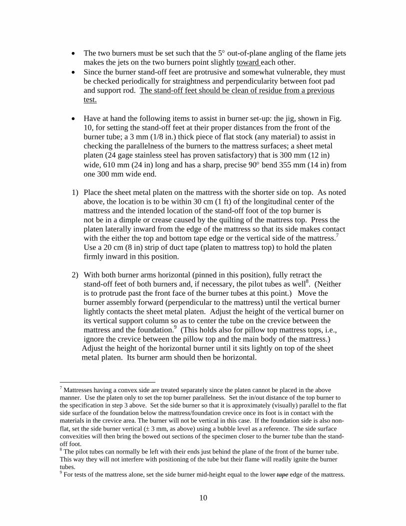
• The two burners must be set such that the 5° out-of-plane angling of the flame jets makes the jets on the two burners point slightly toward each other.
• Since the burner stand-off feet are protrusive and somewhat vulnerable, they must be checked periodically for straightness and perpendicularity between foot pad and support rod. The stand-off feet should be clean of residue from a previous test.
• Have at hand the following items to assist in burner set-up: the jig, shown in Fig.
10, for setting the stand-off feet at their proper distances from the front of the burner tube; a 3 mm (1/8 in.) thick piece of flat stock (any material) to assist in checking the parallelness of the burners to the mattress surfaces; a sheet metal platen (24 gage stainless steel has proven satisfactory) that is 300 mm (12 in) wide, 610 mm (24 in) long and has a sharp, precise 90° bend 355 mm (14 in) from one 300 mm wide end.
1) Place the sheet metal platen on the mattress with the shorter side on top. As noted above, the location is to be within 30 cm (1 ft) of the longitudinal center of the mattress and the intended location of the stand-off foot of the top burner is not be in a dimple or crease caused by the quilting of the mattress top. Press the platen laterally inward from the edge of the mattress so that its side makes contact with the either the top and bottom tape edge or the vertical side of the mattress.7 Use a 20 cm (8 in) strip of duct tape (platen to mattress top) to hold the platen firmly inward in this position. 2) With both burner arms horizontal (pinned in this position), fully retract the
stand-off feet of both burners and, if necessary, the pilot tubes as well8. (Neither is to protrude past the front face of the burner tubes at this point.) Move the burner assembly forward (perpendicular to the mattress) until the vertical burner lightly contacts the sheet metal platen. Adjust the height of the vertical burner on its vertical support column so as to center the tube on the crevice between the mattress and the foundation.9 (This holds also for pillow top mattress tops, i.e., ignore the crevice between the pillow top and the main body of the mattress.) Adjust the height of the horizontal burner until it sits lightly on top of the sheet metal platen. Its burner arm should then be horizontal.
7 Mattresses having a convex side are treated separately since the platen cannot be placed in the above manner. Use the platen only to set the top burner parallelness. Set the in/out distance of the top burner to the specification in step 3 above. Set the side burner so that it is approximately (visually) parallel to the flat side surface of the foundation below the mattress/foundation crevice once its foot is in contact with the materials in the crevice area. The burner will not be vertical in this case. If the foundation side is also non-flat, set the side burner vertical (± 3 mm, as above) using a bubble level as a reference. The side surface convexities will then bring the bowed out sections of the specimen closer to the burner tube than the stand-off foot. 8 The pilot tubes can normally be left with their ends just behind the plane of the front of the burner tube. This way they will not interfere with positioning of the tube but their flame will readily ignite the burner tubes. 9 For tests of the mattress alone, set the side burner mid-height equal to the lower tape edge of the mattress.
10

3) Move the horizontal burner in/out (loosen the thumb screw near the pivot point) until the outer end of the burner tube is 13 mm to 19 mm (1/2 in to 3/4 in) from the corner bend in the platen (this is facilitated by putting a pair of lines on the top of the platen 13 mm and 19 mm from the bend and parallel to it). Tighten the thumb screw. 4) Make the horizontal burner parallel to the top of the platen (within 3 mm, 1/8 in over the burner tube length) by bending the copper tube section appropriately. Note: After the platen is removed (Step 7 below), the burner tube may not be horizontal; this is normal. For mattress/foundation combinations having nominally flat, vertical sides, the similar adjustment for the vertical burner is intended to make that burner parallel to the sides and vertical. Variations in the
shape of mattresses and foundations can cause the platen section on the side to be non-flat and/or non-vertical. If the platen is flat and vertical, make the vertical burner parallel to the side of the platen (± 3 mm) by bending its copper tube section as needed. If not, make the side burner parallel to the mattress/foundation sides by the best visual estimate after the platen has been removed.
5) Move the burner assembly perpendicularly back away from the mattress about 30 cm (1 ft). Set the two stand-off feet to their respective distances using the jig designed for this purpose. Install the jig fully onto the burner tube (on the same side of the tube as the stand-off foot), with its side edges parallel to the burner feed arm, at about the position where one end of the foot will be. Loosen the set screw and slide the foot out to the point where it is flush with the bottom end of the jig. Tighten the set screw. Make sure the long axis of the foot is parallel to the burner tube. IT IS ESSENTIAL TO USE THE CORRECT SIDE OF THE SPACER JIG WITH EACH BURNER. DOUBLE CHECK THIS. THE JIG MUST BE CLEARLY MARKED.
6) Set the downward force of the horizontal burner. Remove the retainer pin near
the pivot. While holding the burner feed arm horizontal using a spring scale10 hooked onto the thumbscrew holding the stand-off foot, move the small and/or large weights on the feed tube appropriately so that the spring scale reads 170 g to 225 g (6 oz to 8 oz).
7) Remove the sheet metal platen (and tape holding it).
8) Hold the horizontal burner up while sliding the burner assembly forward until its stand-off foot just touches the mattress and/or the foundation11, then release the horizontal burner. The outer end of the burner tube should extend at least 6 mm
10 An acceptable spring scale has a calibrated spring mounted within a holder and hooks on each end. Ohaus Scale Corp (Florham Park, NJ) makes a very inexpensive spring scale with a 58 mm (2 ¼ in) range of movement in response to a 250 g (9 oz) weight that is adequate for this purpose. 11 The foot should depress the surface it first contacts by no more than 1 mm to 2 mm. This is best seen up close, not from the rear of the burner assembly. However, if a protruding tape edge is the first item contacted, compress it until the foot is in the plane of the mattress/foundation vertical sides. The intent here is that the burner be spaced a fixed distance from the vertical mattress/foundation sides, not from an
11

to 12 mm (1/4 in. to ½ in.) out beyond the uppermost corner/edge of the mattress so that the burner flames will hit the tape edge. (For a pillow top mattress, this means the outer edge of the pillow top portion and the distance may then be greater than 6 mm to 12 mm ( ¼ in. to ½ in.)) If this is not the case, move the burner assembly (perpendicular to the mattress side) – not the horizontal burner alone - until it is. Finally, move the vertical burner tube until its stand-off foot just touches the side of the mattress and/or the foundation. (Use the set screw near the vertical burner pivot.)
9) Make sure all thumbscrews are adequately tightened. 10) If there is any indication of flow disturbances in the test facility which cause the
burner flames or pilot flames to move around, place screens around the burners so as to minimize these disturbances12. These screens (and any holders) must be far enough away from the burners (ca. 30 cm (12 in.) or more for the top, less for the side) so that they do not interact with the flames growing on the mattress/foundation surfaces. For the top surface burner, a triple layer of window screen approximately 30 cm (12 in.) high sitting vertically on the mattress top (Fig. 9) has proved satisfactory. For the side burner a triple layer of screen approximately 15 cm (6 in.) wide, formed into a square-bottom U-shape and held from below the burner has proved satisfactory. Individual laboratories will have to experiment with the best arrangement for suppressing flow disturbances in their facility.
11) Proceed with the test (see Test Procedure below and Appendix A).
Support structure. See Fig. 1; the arrangement shown there applies to all test configurations. The mattress is centered on top of the foundation (except as noted below). The mattress/foundation assembly is placed on top of a short welded bed frame (1.90 m by 0.99 m by 115 mm high; 75 in by 39 in by 4.5 in high) made from 25 mm (1 in) steel angle. The frame is to be completely open under the foundation except for two crosspieces, 25 mm wide (1 in) at the 1/3 length points. The bed frame feet rest on a surface of either calcium silicate board or fiber cement board of the type used as underlay for tile flooring, 13 mm (0.5 in) thick, 2.11 m by 1.19 m (83 in by 47 in). This surface must be cleaned between tests to avoid build-up of combustible residues. Lining this surface with aluminum foil to facilitate cleaning is not recommended since this might increase fire intensity via reflected radiation. The board serves as a catch surface for any flaming melt/drip material falling from the bed assembly and may be the location of a pool fire that consumes such materials. The low bed frame height is chosen to allow
incidental protrusion. Similarly, if there is a wide crevice in this area which would allow the foot to move inward and thereby place the burners too close to the vertical mattress/foundation sides, it will be necessary to use the spacer jig (rather than the stand-off foot) above or below this crevice to set the proper burner spacing. Compress the mattress/foundation surface 1 mm to 2 mm when using the jig for this purpose. 12 The goal here is to keep the burner flames impinging on a fixed area of the specimen surface rather than wandering back and forth over a larger area.
12

interaction between such a pool fire and the bed assembly. The bed frame and bed are centered on this catch surface. The catch surface is optionally raised above the floor of the test facility by 25 cm (10 in) by placing it on top of a steel framework capable of supporting the weight of the bed assembly. The added height is not believed to affect system performance; it may ease the set-up process for the test operator. Heat Release Rate Measurement. Heat release rate measurements in all three configurations shall follow the procedures and instrumentation recommendations described in detail in ASTM E 1590. The only change is in the calibration levels of the system from 40 and 160 kW to 75 and 200 kW. Video Recording. Place a video camera so as to have (when the lens is zoomed out) just slightly more than a full-length view of the side of the test specimen being ignited, including a view of the flame impingement area while the burner assembly is present. The view must also include the catch pan so that it is clear whether any melt pool fire in this pan participates significantly in the growth of fire on the test specimen. The camera is to include a measure of elapsed time to the nearest 1 s within its recorded field of view (preferably built-in to the camera). For the room-based configurations, the required full-length view of the sample may require an appropriately placed window, sealed with heat resistant glass, in one of the room walls. Place the camera at a height just sufficient to give a view of the top of the specimen while remaining under any smoke layer that may develop in the room. The specimen is to be brightly lighted so that the videotape does not lose detail to over-exposed flames. This will require a pair or more of 1 kW photo flood lights illuminating the viewed side of the specimen. The lights may need to shine into the room from the outside via sealed windows. It is useful, in testing prototype designs, to have an observer narrate fire and/or specimen behavior to the videotape, using a remote microphone since fine details are typically more visible to an observer than to the camera. Key issues to note are penetration (if any) of barrier materials or seams in the mattress and/or the foundation, appearance of flames in the interior of the mattress and/or foundation and any occurrence of an abrupt over-pressurization in the mattress (very briefly swelling the mattress and possibly opening barrier seams). Crackling sounds, indicating fire involvement of the wood in the base of the foundation, are also important markers of fire progression in the foundation interior. Test Procedure Initial Conditions: The ambient temperature shall be above 12 °C (54 °F)and the relative humidity must be below 70%. Test specimens are to have been conditioned for at least 24 hours within these limits prior to testing. Horizontal air flow at a distance of 0.5 m (20 in) on all sides of the test specimen at the mattress top height shall be ≤ 0.5 m/s (1.6 ft/s). If there is any visual evidence that the burner flames are being shifted around during their exposure durations, the burner
13

regions must be enclosed on two or more sides by a quadruple layer of screen wire. The screen(s) for the top burner sits on the mattress top but must be far enough away (typically 30 cm (12 in.) or more) so as not to interfere or interact with flame spread during the burner exposure. The screen for the side burner will require a separate support from below. All screens are to be removed at the end of the 70 s exposure interval. Remove the test specimen from the conditioning room immediately before it is to be tested. Be sure the bed frame is approximately centered on the catch surface. Place the mattress and foundation on the bed frame. Carefully center them on the bed frame and on each other13. Place the burner assembly adjacent to the test specimen and align/space the burner heads as described above. Be sure the alignment platen is removed from the test specimen. Care must be taken, once this set-up is achieved, to avoid bumping the burner assembly or disturbing the flexible lines that bring propane to it. Charge the hose line to be used for fire suppression with water. Ignite the pilot lights on both burners and make sure they are small enough as to not heat the test specimen surfaces significantly. With the calorimetry system fully operational, after instrument zeroes and spans, start the video lights and video camera and data logging systems at least one minute before burner ignition. Start the burner exposure by activating power to the burner timers. When the burners go out (after 70 s for the longer exposure), carefully lift the top burner tube away from the specimen surface, producing as little as possible disturbance to the specimen. Remove the burner assembly from the specimen area to facilitate the video camera view of the full side of the specimen. In the case of the room-based configurations, remove the burner assembly from the room to protect it. Remove all screens. Record the heat release rate and video view until one the following has occurred:
• All signs of burning have ceased (smoldering, as indicated by continued smoke emission, may transition into flaming; it is considered here to be a form of burning)
• 30 minutes has elapsed since the start of the burner exposure. (The test ends at 30 minutes. For informational purposes in assessing a new design, it may be useful to continue longer if the heat release rate is at least 50 kW and is increasing.)
13 If the mattress is 1 cm to 2 cm (0.5 in. to 1 in.) narrower than the foundation and can be plausibly shifted so that the side to be exposed is in the same plane as the foundation, do so. This keeps the heat flux exposure the same for the sides of the two components.
14

• Development of a fire of such size as to require suppression for the safety of the facility
Note the time and nature of any unusual behavior that is not fully within the view of the video camera. This is most easily done by narration to a camcorder. Run the heat release rate system and datalogger until the fire has been fully out for several minutes to allow the system zero to be recorded. If the test ends at 30 minutes with some residual combustion and it is not to be followed further, suppress it to permit this zero recovery. Test Criteria A mattress, a futon or a mattress/box spring set fails to meet the requirements of this test procedure if any of the following criteria are exceeded: • A peak rate of heat release of 200 kW. • A total heat release of 25 MJ in the first 10 minutes of the test. Report The test report includes the identity of the testing laboratory, the identification and any available compositional details of the test specimen, the test date and the conditions of both pre-conditioning (relative humidity and temperature) and testing (relative humidity and temperature). Also include any notes (with timing) on unusual behavior of the specimen during the test that may not have been captured on the video. The body of the report contains graphs of heat release rate versus time from two minutes before the start of ignition all the way through the zero recovery period, along with a tabulation of the measured data that goes into the heat release rate calculation. If requested, calculate gas yields in accord with the procedure given in ASTM 1590. Include the videotape with any narration of the test.
15

Appendix A: Burner Operation Sequence (Applies to L&P Version of the Burner Assembly)
Starting point:
AC power on (red knob out); propane pressure set between 10 to 20 psig at bottle; timers set to 70 s (top burner) & 50 s (side burner); flowmeters pre-set to values that give the requisite propane gas flow rates to each burner. Pilot tubes set just behind front surface of burners; pilot flow valves set for ca. 1 cm (1/2 in.) flames.
Position burner on test specimen and remove sheet metal platen. Place screens around both burners. Open pilot ball valves one at a time and ignite pilots with hand-held flame; adjust flame size if necessary being very careful to avoid a jet flame that could prematurely ignite the test specimen (Beware: after a long interval between tests the low pilot flow rate will require a long time to displace air in the line and achieve the steady-state flame size.) Open both burner ball valves. Start test exposure by simultaneously turning on power to both timers (timers will turn off burners at appropriate times.) Check/adjust propane flow rates (DO THIS ESSENTIAL TASK IMMEDIATELY. Experience shows the flow will not remain the same from test-to-test in spite of fixed valve positions so adjustment is essential.) After burners are out: Lift top burner and back assembly away from specimen
Turn off power to both timers Remove screens (if used) Turn off pilots at their ball valves
16
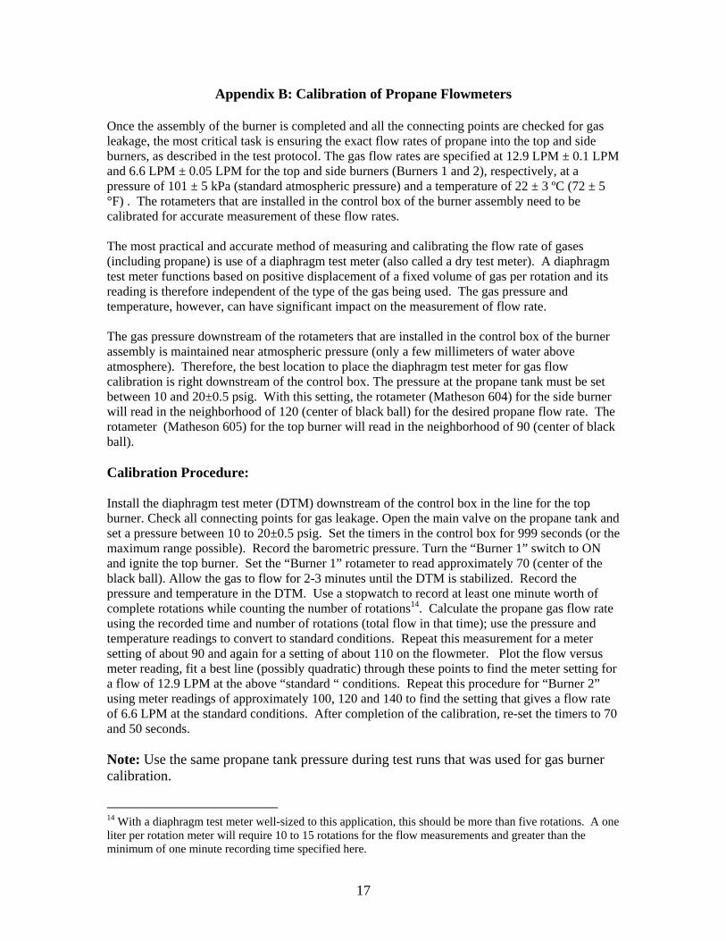
Appendix B: Calibration of Propane Flowmeters Once the assembly of the burner is completed and all the connecting points are checked for gas leakage, the most critical task is ensuring the exact flow rates of propane into the top and side burners, as described in the test protocol. The gas flow rates are specified at 12.9 LPM ± 0.1 LPM and 6.6 LPM ± 0.05 LPM for the top and side burners (Burners 1 and 2), respectively, at a pressure of 101 ± 5 kPa (standard atmospheric pressure) and a temperature of 22 ± 3 ºC (72 ± 5 °F) . The rotameters that are installed in the control box of the burner assembly need to be calibrated for accurate measurement of these flow rates. The most practical and accurate method of measuring and calibrating the flow rate of gases (including propane) is use of a diaphragm test meter (also called a dry test meter). A diaphragm test meter functions based on positive displacement of a fixed volume of gas per rotation and its reading is therefore independent of the type of the gas being used. The gas pressure and temperature, however, can have significant impact on the measurement of flow rate. The gas pressure downstream of the rotameters that are installed in the control box of the burner assembly is maintained near atmospheric pressure (only a few millimeters of water above atmosphere). Therefore, the best location to place the diaphragm test meter for gas flow calibration is right downstream of the control box. The pressure at the propane tank must be set between 10 and 20±0.5 psig. With this setting, the rotameter (Matheson 604) for the side burner will read in the neighborhood of 120 (center of black ball) for the desired propane flow rate. The rotameter (Matheson 605) for the top burner will read in the neighborhood of 90 (center of black ball). Calibration Procedure: Install the diaphragm test meter (DTM) downstream of the control box in the line for the top burner. Check all connecting points for gas leakage. Open the main valve on the propane tank and set a pressure between 10 to 20±0.5 psig. Set the timers in the control box for 999 seconds (or the maximum range possible). Record the barometric pressure. Turn the “Burner 1” switch to ON and ignite the top burner. Set the “Burner 1” rotameter to read approximately 70 (center of the black ball). Allow the gas to flow for 2-3 minutes until the DTM is stabilized. Record the pressure and temperature in the DTM. Use a stopwatch to record at least one minute worth of complete rotations while counting the number of rotations14. Calculate the propane gas flow rate using the recorded time and number of rotations (total flow in that time); use the pressure and temperature readings to convert to standard conditions. Repeat this measurement for a meter setting of about 90 and again for a setting of about 110 on the flowmeter. Plot the flow versus meter reading, fit a best line (possibly quadratic) through these points to find the meter setting for a flow of 12.9 LPM at the above “standard “ conditions. Repeat this procedure for “Burner 2” using meter readings of approximately 100, 120 and 140 to find the setting that gives a flow rate of 6.6 LPM at the standard conditions. After completion of the calibration, re-set the timers to 70 and 50 seconds. Note: Use the same propane tank pressure during test runs that was used for gas burner calibration.
14 With a diaphragm test meter well-sized to this application, this should be more than five rotations. A one liter per rotation meter will require 10 to 15 rotations for the flow measurements and greater than the minimum of one minute recording time specified here.
17

Appendix B: Calibration of Propane Flowmeters Once the assembly of the burner is completed and all the connecting points are checked for gas leakage, the most critical task is ensuring the exact flow rates of propane into the top and side burners, as described in the test protocol. The gas flow rates are specified at 12.9 LPM ± 0.1 LPM and 6.6 LPM ± 0.05 LPM for the top and side burners (Burners 1 and 2), respectively, at a pressure of 101 ± 5 kPa (standard atmospheric pressure) and a temperature of 22 ± 3 ºC (72 ± 5 °F) . The rotameters that are installed in the control box of the burner assembly need to be calibrated for accurate measurement of these flow rates. The most practical and accurate method of measuring and calibrating the flow rate of gases (including propane) is use of a diaphragm test meter (also called a dry test meter). A diaphragm test meter functions based on positive displacement of a fixed volume of gas per rotation and its reading is therefore independent of the type of the gas being used. The gas pressure and temperature, however, can have significant impact on the measurement of flow rate. The gas pressure downstream of the rotameters that are installed in the control box of the burner assembly is maintained near atmospheric pressure (only a few millimeters of water above atmosphere). Therefore, the best location to place the diaphragm test meter for gas flow calibration is right downstream of the control box. The pressure at the propane tank must be set between 10 and 20±0.5 psig. With this setting, the rotameter (Matheson 604) for the side burner will read in the neighborhood of 120 (center of black ball) for the desired propane flow rate. The rotameter (Matheson 605) for the top burner will read in the neighborhood of 90 (center of black ball). Calibration Procedure: Install the diaphragm test meter (DTM) downstream of the control box in the line for the top burner. Check all connecting points for gas leakage. Open the main valve on the propane tank and set a pressure of 20±0.5 psig. Set the timers in the control box for 999 seconds (or the maximum range possible). Record the barometric pressure. Turn the “Burner 1” switch to ON and ignite the top burner. Set the “Burner 1” rotameter to read approximately 70 (center of the black ball). Allow the gas to flow for 2-3 minutes until the DTM is stabilized. Record the pressure and temperature in the DTM. Use a stopwatch to record at least one minute worth of complete rotations while counting the number of rotations15. Calculate the propane gas flow rate using the recorded time and number of rotations (total flow in that time); use the pressure and temperature readings to convert to standard conditions. Repeat this measurement for a meter setting of about 90 and again for a setting of about 110 on the flowmeter. Plot the flow versus meter reading, fit a best line (possibly quadratic) through these points to find the meter setting for a flow of 12.9 LPM at the above “standard “ conditions. Repeat this procedure for “Burner 2” using meter readings of approximately 100, 120 and 140 to find the setting that gives a flow rate of 6.6 LPM at the standard conditions. After completion of the calibration, re-set the timers to 70 and 50 seconds. Note: Use the same propane tank pressure during test runs that was used for gas burner calibration.
15 With a diaphragm test meter well-sized to this application, this should be more than five rotations. A one liter per rotation meter will require 10 to 15 rotations for the flow measurements and greater than the minimum of one minute recording time specified here.
18

FIGURE 1. TEST ASSEMBLY, SHOWN IN FURNITURE CALORIMETER. (CONFIGURATION A.)
FOUNDATION
MATTRESS
FURNITURE CALORIMETER HOOD
OPTIONAL HOOD SKIRT
BEDFRAME
CATCH SURFACE OF CEMENT FIBERBOARD
91
cm
( 3
6 in
) M
AXIM
UM
{OPTIONAL ELEVATED SUPPORT
19

FIGURE 2 . TEST ARRANGEMENT IN 2.44 m x 3.66 m (8 ft x 12 ft) ROOM; CONFIGURATION B.
0.76 m (30 in)
2.44 m (8 ft)3.
66 m
(12
ft)
13 - 17 cm (5 - 6.7 in) CATCH
SURFACEAPPROX. BURNER FOOT- PRINT
MATT / FDN ON BEDFRAME
25 - 30 cm (10 - 12 in)
20

FIGURE 3. TEST ARRANGEMENT IN 3.05 m x 3.66 m (10 ft x 12 ft) ROOM; CONFIGURATION C.
0.97 m (38 in)
3.66 m (12 ft)
3.05
m (1
0 ft)
25 - 30 cm (10 - 12 in)
CATCH SURFACE
APPROX. BURNER FOOT- PRINT
13 - 17 cm (5 - 6.7 in)
MATT / FDN ON BEDFRAME
21

30.4
8 cm
(1
2 in
)
TOP AND BOTTOM ENDS CAPPED WITH GAS-TIGHT WELDED SEAL
JOINED AT 90 BY GAS-TIGHT WELD
O
( 0.8
5 cm
(1/3
") A
PAR
T C
ENTE
R- T
O-C
ENTE
R)
17 H
OLE
S EV
ENLY
SPA
CED
O
VER
13.
5 cm
(5.3
3 in
) LEN
GTH
( 0.8
5 cm
(1/3
") A
PAR
T C
ENTE
R- T
O-C
ENTE
R)
0.85 cm0.85 cm
Stainless Steel Tubing 1.27 cm OD with 0.0889 cm wall (0.5 in OD x 0.035 in wall)
17 H
OLE
S EV
ENLY
SPA
CED
O
VER
13.
5 cm
(5.3
3 in
) LEN
GTH
FIGURE 4. DETAILS OF HORIZONTAL BURNER HEAD.
Stainless Steel Tubing 1.27 cm (0.50) OD with 0.0889 cm (0.035 in) wall
o o
o
o
o o
o
o
o o
o
o
o o
o
o
o
o
o o
o
o
o o
o
o
o o
o
o
o
o o
o
HOLES ARE NOMINALLY 1.17 mm DIA. (0.046 in) (#56 DRILL) HOLES ARE ALL IN A LINE AND POINT 5 OUT OF THE PLANE OF THE DIAGRAM
O
22

25.4
cm
(1
0 in
)
TOP AND BOTTOM ENDS CAPPED WITH GAS-TIGHT WELDED SEAL
( 0.8
5 cm
(0.3
3 in
) APA
RT
CEN
TER
- TO
-CEN
TER
)
14 H
OLE
S EV
ENLY
SPA
CED
O
VER
11.
00 c
m (4
.33
in) L
ENG
TH( 0
.85
cm (0
.33
in) A
PAR
T C
ENTE
R- T
O-C
ENTE
R)
0.85 cm0.85 cm
Stainless Steel Tubing 1.27 cm OD with 0.0889 cm wall (0.5 in OD x 0.035 in wall)
14 H
OLE
S EV
ENLY
SPA
CED
O
VER
11.
00 c
m (4
.33
in) L
ENG
TH
FIGURE 5. DETAILS OF VERTICAL BURNER HEAD.
o o
o
o
o o
o
o
o o
o
o
o
o
o
o
o o
o
o
o o
o
o
o o
o
o
Stainless Steel Tubing 1.27 cm (0.50 in) OD with 0.0889 cm (0.035 in) wall
JOINED AT 90 BY GAS-TIGHT WELD
O
HOLES ARE NOMINALLY 1.17 mm DIA. (0.046 in) (#56 DRILL) HOLES ARE ALL IN A LINE AND POINT 5 OUT OF THE PLANE OF THE DIAGRAM
O
23

FIGURE 6. DETAILS OF BURNER STAND-OFF
FRONT VIEW END VIEW
COLLAR HOLDING STAND-OFF
BURNER HOLES POINTING 5 OUT OF BURNER PLANE, AWAY FROM STAND-OFF
o
------o--------o--------o--------o----------------o--------o--------o--------o------
o5
STAND-OFF FOOT 12.7 mm x 50.8 mm (0.50 x 2.0 in)
12.7 mm (0.50 in)
50.8 mm (2.0 in)
24

Figure 7. Burner Assembly Showing Arms and Pivots (Shoulder Screws) in Relation to Portable Frame Allowing Burner Height Adjustment.
25

BURNER
From Propane Bottle with Pressure Regulator Set to 20 psig SOLENOID
VALVE
FIGURE 8. ELEMENTS OF PROPANE FLOW CONTROL FOR EACH BURNER
On/Off
FLOW CONTROL
o
o
o
o
o
o o
o
FLOW METER
TIME DELAY RELAY
TO SECOND BURNER
PILOT
FLOW CONTROLDuplicate Flow
Controls for Second Burner
26

FIGURE 9. BURNER PLACEMENTS ON MATTRESS / FOUNDATION
MATTRESS
FOUNDATION
42.0 mm (1.65 in)
SIDE VIEW
TOP BURNER
39.0 mm (1.54 in)
MATTRESS TOP
TOP BURNER
18 - 20 cm (7.1 - 7.9 in)
SIDE BURNER
FLAT PLATEN
TOP VIEW
SCREENSCREEN
SCREEN
SIDE BURNER
27

FIGURE 10. JIG FOR SETTING BURNERS AT PROPER DISTANCES FROM MATTRESS / FOUNDATION
++
TOP BU
RN
ERSI
DE
BUR
NER
12.7 mm (1/2 in)
11.11mm (7/16 in)6.35 mm (1/4 in)
5.08 cm (2.00 in)PLACEMENT AND DIAMETER NOT CRITICAL (THIS HOLE IS JUST FOR LOWERING THE WEIGHT OF THE JIG).
NOTE: PUNCH WORDS SHOWN ON BOTH FLAT FACES OF JIG.
39 m
m
0.
10 m
m
(1.5
35in
0
.004
in)
+ _ + _
12.7
mm
(- 0
.0 ,
+ 0.
1) m
m
0.50
0 in
(-0.
000
, +0.
005i
n){
58.7
mm
(2
.31
in)
42 m
m
0.
10 m
m
(1.6
54 in
0
.004
in)
+ _ + _
12.7
mm
(- 0
.0 ,
+ 0.
1) m
m
0.50
0 in
(-0.
000
, +0.
005
in)
{
TWO HOLES DRILLED THROUGH AND TAPPPED 6-32
2.54 cm (1.0 in)
28