Embed Size (px)
Citation preview
r SENT BY:xerox Telecopier 7021 9-24-96 14: 07 Q&Ril.-+
GARY E JOHNSON Governor
Mr. Kent Hunter
State of New Mexico ENVIRONMENT DEPARTMENT
DOE Oversight Bureau I Waste Isolation Pilot Plant Site Office P.O. Box 3U91f. WIPP Site, Jal Highway
Carlsba(/, New Mexico 88221 Telephone: (505) 234-8P47 Fax: (505) 887-5871 -···--.. +~----·
National TRU Program/Operations Manager U.S.DepartinenlofEncrgy Carll>bitd An..-u 01licc P. 0. Box 3090 Carlsbad, NM 88221-3090
Subject: WIPP Borehole Assessment
Dear Mr. Hunter:
15058271545;# 7
MARKE WEIDLF.R. Secntary
EDGAR T. 1110RNl'ON, lll ~P"1Y Sec:retury
The WIPP Oversight Office of the New Mexico Enviro · ent Department (NMED) DOE Oversight Bureau has completed an evalµation of boreholes within 1he WIPP Land Wi1hdratBoundary (L WB). Attached please f""md a report providing the results of our evaluation and some preliminary recomm dations. The report is provided to communicate technical information and recommendations resulting from 1he bo le evaluation. The report is not provided or int.ended for the purpose of representing 1he regulatocy position of the Ne Mexico Environment Department or other state or federal agencies,
This activity grew out of concerns conveyed by membe~ of the public that, within the WIPP LWB, boreholes may provide a conduit for 1he release of radioactive contaminants from lbe proposed geological repositocy at 1lhe WIPP.
This information may be incorporated at a later date into ~ fonnal technical report of the New Mexico Environment Department. It is being released to you now as an in1orn¥U report so that the WIPP project may benefit from the infoJ:Dl4tion it contains. Should you have any questions regarding the c9ntents of the report, I may be reached at the NMED WIPP Oversight Utlice prior to October l, 1996. After that time you shord contact John Paxker, of the DOE Oversight Bureau in Santa Fe at 505-827-1536.
Sincerely,
Keith E. McKam.ey Health Program Manager W U'l' Oversight Office DOE Oversight Burean
Enclosure
cc w/enclosure: Neil Weber EdKelk:y John Purker
960915
1111111 lllll lllll lllll lllll lllll llll llll
r
NMED/DOE/ AIP-96/3/96Bore.kem
NMED/DOE OVERSIGHT BURE:AU
1996 WASTE ISOLATION PILOT PLANT
ENVIRONMENTAL BOREHOLE REPORT
GROUNDWATER ISSUES
NMED/DOE/ AIP
Prepared by
Keith E. McKamey Health Program Manager I/DOE-OB/WIPP
STATE OF NEW MEXICO
T
NMED/DOE/ AIP-96/3/96Bore.kem
CONTENTS
ACRONYMS ................................................................. 1
1.0 EXECUTIVE SUMMARY ................................................ 2
2.0 REASONS FOR INVESTIGATION ......................................... 2 2.1 INTRODUCTION ................................................. 2 2.2 WATER LEVELS ................................................. 2 2.3 WATER QUALITY/CHEMISTRY ................................... 3 2.4 DEVON/TEXAS AMERICAN TODD 26 F #3 FED. (N\\l 1/4 26-23S-31E) ... 4 2.5 YATES #1 ROSS AIT FEDERAL (NE 114 35-22S-31E) ................... 4 2.6 GRACE #1 CABIN BABY (NE 1/4 5-23S-31E) ......................... 4 2. 7 CASING AND CEMENT PRACTICES ................................ 4
2.7.1 Oil and Gas Industry Standard .................................. 5 2.7.2 Problem Zones .............................................. 5 2.7.3 Pathway to the Environment ................................... 5 2.7.4 Borehole Verification ......................................... 5
3.0 BOREHOLE INTEGRITY EVALUATIONS OIL AND GAS WELLS ............. 6 3.1 OIL AND GAS HISTORY .......................................... 6 3.2 REGULATIONS .................................................. 6 3.3 LIST OF BOREHOLES AND AREA OF STUDY ....................... 8 3.4 EXAMPLES OF POTENTIAL PROBLEM WELLS ...................... 8 3.5 CONTRACTOR SUMMARY ........................................ 9 3.6 BOREHOLE INTEGRITY TOOL LIMITATIONS ...................... 10
4.0 BOREHOLE INTEGRITY EVALUATION-TEST WELLS WITHIN LAND WITHDRAWAL BOUNDARY ........................................... 10 4.1 REGULATIONS (Boreholes and Shafts) .............................. 10 4.2 LIST OF BOREHOLES AND AREA OF STUDY ...................... 11 4.3 EXAMPLES OF PROBLEM WELLS ................................ 11 4.4 BOREHOLE SEALING ........................................... 12 4.5 CONTRACTOR SUMMARY ....................................... 12
5.0 CONCLUSION ........................................................ 13
6.0 REFERENCES ........................................................ 14
11

NMED/DOE/ AIP-96/3/968ore.kem
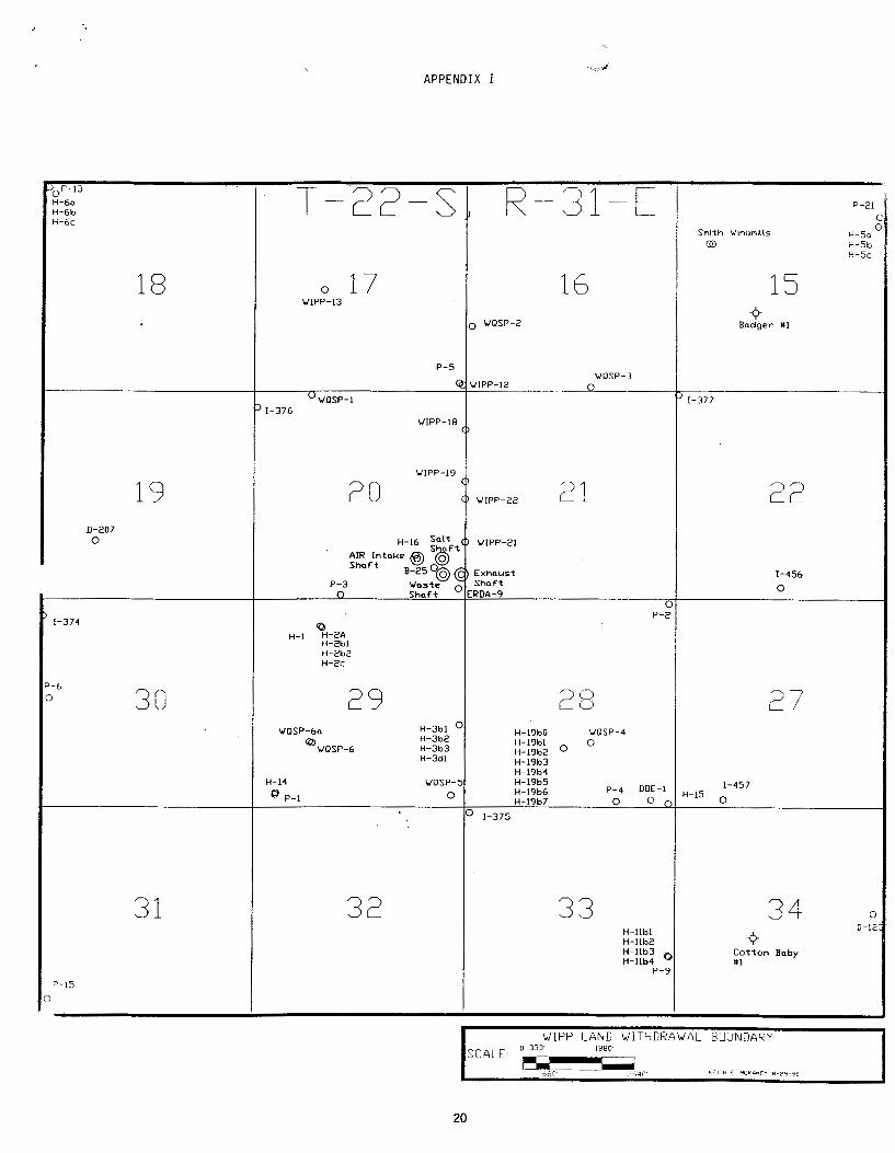
APPENDIX I ................................................................ 17 MAP ................................................................. 17
APPENDIX II ............................................................... 18 GEOLOGIC CROSS SECTION ........................................... 18
APPENDIX III ............................................................... 19 YATES #1 ROSS AIT FEDERAL (NE 1/4 35-22S-31E) ........................ 19
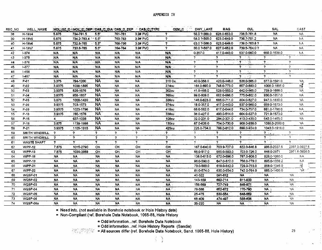
APPENDIX IV ............................................................... 21 BOREHOLE DATABASE ............................................... 21
APPENDIX V ............................................................... 30 TABLE OF BOREHOLES WITH DEFICIENCIES ............................ 30
FIGURE 1 & 2 ............................................................... 31 HARGROVE # 1 PICTURES ............................................ 31
FIGURE 3 .................................................................. 33 YATES #1 ROSS AIT FED. - PICTURES ................................... 33
111
NMED/DOE/AIP-96/3/96Bore.kem
ACRONYMS
AIP ........................... Environmental Oversight and Monitoring Agreemi;!nt Between the U.S. Department of Energy and the State of New _Mexico, October 22, 1990
BCF......................... Billion Cubic Feet (of gas) BWPM ..................... Barrels of water per month CAO ......................... Carlsbad Area Office of the DOE CH............................ Contact Handled TRU-waste DOE-OB ................... New Mexico Environment Department DOE Oversight Bureau DOE ......................... U.S. Department of Energy EMOP...................... 1995 NMED/WIPP Environmental Monitoring and Oversight Plan EMP ......................... WIPP Environmental Monitoring Plan, DOE/WIPP 94-024 EPA .......................... U.S. Environmental Protection Agency L WB.......... .. . ... . .. .. . ... Land Withdrawal Boundary NMED ...................... State of New Mexico Environment Department NQA ......................... Nuclear Quality Assurance OCD......................... Oil Conservation Division RCRA...... ... ... . .. ... ... . . Resource Conservation and Recovery Act RH............................ Remote Handled TRU-waste SWD......................... Salt Water Disposal TD............................ Total Depth TOC ......................... Top of Cement WIPP ........................ Waste Isolation Pilot Plant
1
NM ED/DOE/ AIP-96/3/96Bore.kem
1.0 EXECUTIVE SUMMARY
The concern addres~ed by this investigation is the potential of a borehole to act as a conduit to release radioactive waste to the environment. State Engineer Regulations require that each water shall be confined to the aquifer in which it is encountered. The boreholes listed in Appendix V may not comply with regulations of the State Engineer Office presuming that the Dewey Lake, Magenta, Culebra, Salado, and Castile formations each encountered water. The investigation determined that 15of74 boreholes (see Appendix V) are suspected as non-compliant with 49 of 74 boreholes inconclusive due to inadequate information available to determine compliance (ref. AIP Borehole Database, Appendix IV; Jim Klaus/CAO letter dated 7-19-96).
Following the plugging of the above-described wells and according to the standards to date, all steps for protecting the environment in boreholes will have been taken. Please note that this investigation does not address the long term stability of the borehole but rather the current regulations which govern producing, plugging, and abandonment of boreholes. The life of the materials used in these boreholes may degrade in one hundred years (Stormont 84) but in theory the self-healing processes of salt will restrict movement of ground water or hazardous materials.
2.0 REASONS FOR INVESTIGATION
2.1 Introduction
The purpose of this investigation is to verify DOE borehole data, review the integrity of on site boreholes and their the ability to collect in-situ ground water free from interzone contamination, and evaluate the potential of boreholes as a pathway for radioactive waste from the stored underground waste repository to the environment. Creditable professionals were contracted to evaluate the off site "industry standard" cementing and cement evaluation methods which this investigation will employ as examples to apply to on site boreholes, since wells within the L WB were not logged to evaluate the: cement integrity.
2.2 Water Levels
This investigation began with stakeholder concern that all the WIPP boreholes were connecting the underground aquifers, creating a potential pathway for radioactive waste release. The reasoning behind this concern was the rise in water levels in boreholes
2
NMED/DOE/ AIP-96/3/96Bore.kem
throughout the site. Of the thirty five wells measured, 71 % recorded a rise (ref. Post 1988 Culebra Water Levels, Rick Beauheim, Sandia), the greatest rise of which was the P-18 well (90' from 1991 to 1995-attributed primarily from replacing 4" casing to 2 3/8" tubing) located 3/4 of a mile southeast of the L WB (section 26-22S-31E) and 2118' North of a water injection well (Yates #1 AIT Ross Federal). The rise in water level in several boreholes is a strong indication that unnatural recharge is occurring from an unknown source, since weather patterns have remained constant throughout the life of these boreholes. Other wells and boreholes with significant water level changes are:
Cabin Baby Water level has dropped from 338' from surface in 1990 to 364' from surface in 1995.
H-14 Water level has increased from the normal 345' from surface in 1991 to 337' from surface in 1995 H-1, H2b2, H3b2, H-16, ERDA 9, WIPP 12, 18, 19, 21, and 22 - Water levels dropped beginning in 1993 due to leakage into the Air Intake Shaft (AIS) (ref. Beauheim June 1995). The Culebra water levels increased when the AIS was grouted in late 1993, but why did the Magenta zones in H-1 and H-16 increase? This may be an indication of cross contamination due to open hole conditions in the H-16 borehole and packer leakage in the H-1 borehole.
DOE-2 Water levels have dropped since 1993
2.3 Water Quality/Chemistry
Water Chemistry changes from the western portion of the site to the eastern portion.
1) Total Dissolved Solids (TDS) in the Culebra change drastically from 5,000 mg/L southwest of the site to >200,000 mg/l on the eastern edge of the site (ref. Crawley, 1988; Holt, 1992; and Siegel, 1991).
2) Dewey Lake TDS ranges from 673 mg/l in the Barn well southwest of the site to 3350 mg/l in the Fairview well southeast of the site.
3) Culebra CaS04 type water southwest of the site and NaCl type water in the eastern part of the site is a significant water chemistry change (ref. Crawley, 1988; Holt, 1992; and Siegel, 1991) . It is not known whether the NaCl type water change occurs in the Dewey Lake since the wells in the eastern part of the site were not analyzed for Calcium and Sodium. Dewey Lake chloride levels also change from 81 mg/Lin the Barn well southwest of the site to 140 mg/Lin the Fairview well southeast of the site.
4) H-1 lb3 chlorides decreased to 56,000 PPM in 1990. Disposal of produced water
3
NMED/DOE/AIP-96/3/96Bore.kem
began in 1991 in the AIT #1 Ross Federal (35-22S-31E) and analysis from 1992 to 1994 indicated an increase in chlorides to 65,500 PPM. Injection fluids in the Yates #1 AIT Ross Federal are 200,000 PPM. This change in chlorides is not significant since fluctuations in chlorides often range as much as 10,000-20,000 PPM from one measurement to the next.
These changes in water chemistry indicate that ground water on the western boundary of the site is intermixing with fresh water and/or that ground water on the eastern part of the site is intermixing with salt water.
2.4 Devonffexas American Todd 26 F #3 Federal (NW 1/4 26-23S-31E)
Located four miles south of the LWB, this water injection well is the suspected cause of the water level rise in ground water in H-9. Deteriorated casing was replaced through the Rustler zone on November 22, 1993.
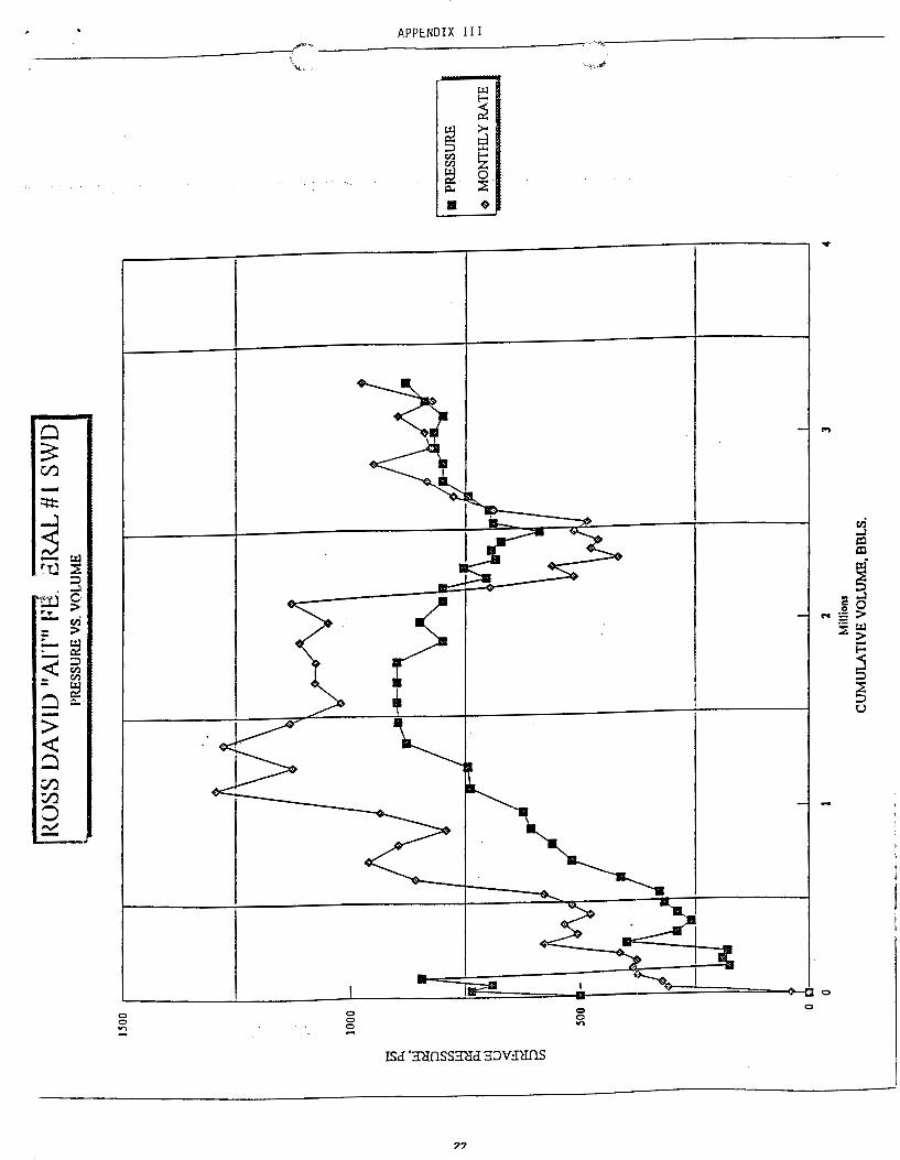
2.5 Yates #1 Ross AIT Federal (NE 114 35-22S-31E)
This salt water disposal well is located three quarters of a mile from the southeast comer of the L WB. The operator fractured the Delaware zone (below the base of the Castile), did not establish the necessary disposal rate, and fractured additional Delaware perforations so disposal of 67,000-104,000 BWPM could be accomplished (ref OCD records 1991-95).
2.6 Grace #1 Cabin Baby Federal (NE 114 5-23S-31E)
This borehole is located 1980' south of the L WB. It was completed at a depth of 4150' and Temporarily Abandoned 2-8-75. Sandia performed slug injection tests in this borehole (ref. Sand87-7125) and DOE has long contended that this well may have a bridge plug failure and could be a possible cause to the rise in water levels in the southern portion of theLWB.
2. 7 Casing and Cement Practices
2.7.1 Oil and Gas Industry Standard
Recently the Oil Conservation Division has required industry wells around WIPP to set surface casing to the base of the Rustler, intermediate casing to the top of the Delaware, and circulate both strings. In the past however, the Cotton Baby (34-22S-31E) completed
4
NMED/DOE/ AIP-96/3/96Bore.kem
in 1975 represents the industry standard. This well was cemented by plugs with the focus on the oil producing zones below the Delaware. Typically, the shallow water aquifers (Magenta, Culebra, Salado, and Castile) are commingled. It is worthwhile to note that it is difficult to seal zones in the Rustler, Salado, and Castile formations due to washout problems addressed in paragraph 3. 7 .2.
2. 7.2 Problem Zones
Historically, water zones and salt/evaporite zones were considered problem zones while drilling and completing. Strong water zones resist good cement bonds and salt/evaporite zones washed out during drilling. The washouts create problems for cement volume calculations and, in some cases where cement is circulated to cover washouts, the pipe was pushed to the side of the hole allowing minimum cement bond between the pipe and formation. In many boreholes and industry wells, however, the salt/evaporite section which contains the Magenta and Culebra Aquifers was left uncemented (see notes Borehole Database H-2A, H3dl, H-16, I-377; Figure 1 - #1 Hargrove).
2.7.3 Pathway to the Environment
Of primary concern in this investigation is the potential pathway to the environment created by the boreholes. Assuming a migration of hazardous waste from the repository to a borehole (ref. Hartman #2 Bates had water injection flow through MB-141), waste could be transported to the surface or to the L WB through ground water flow and be consumed by animals, plants and humans (i.e. air, ingestion). Unsealed boreholes allow cross contamination from zone to zone, therefore potentially spreading the contamination.
2.7.4 Borehole Verification
Borehole verification consisted of listing the completion and plugging components of each borehole into a database format. Cement volume calculations were made using Halliburton/Western formulas to determine depth covered by the amount of cement used. Compliance was assessed based on the known zone levels (i.e. database intervals: Dewey Lake, Magenta, Culebra, Salado, and Castile) and the calculated cement covered intervals (i.e. database "Cement" column).
5
NMED/DOE/ AJP-96/3/96Bore.kem
3.0 BOREHOLE INTEGRITY EVALUATION-OIL AND GAS WELLS
3.1 Oil and Gas History
The oil and gas picture surrounding WIPP has changed from its conception to the present. Four Control Zones were originally established to restrict activity that would affect the WIPP site. The outside or Control Zone IV restricted drilling activity approximately one mile beyond the 16-section L WB. These zones are now reduced to fit within the L WB (ref. WIPP Site Environmental Report 1995). Oil and gas reserves were thought to be of no economic consequence since the WIPP was located in a structural syncline. Today analogies can be drawn that show WIPP's 16-section boundary is structurally analogous to and on trend with the prolific Sand Dunes, Los Medanos, and Cabin Lake Fields. Ron Broadhead et al in 1995 calculated 12.3 million barrels of oil and gas condensate and 186 BCF gas recoverable by primary production methods from probable resources within the L WB and an additional one mile boundary surrounding WIPP. These reserves are very conservative due to calculations based on 150 barrels per month as the economic limit (industry uses 50-75 barrels per month), using 10% Discount rate calculated from Beta values (These Beta values are company wide and basin wide projections. Discount rates calculated from the surrounding WIPP Delaware play should be used. Note: There are no l 990's vintage dry holes surrounding WIPP, therefore, success ratios surrounding WIPP of greater than ninety five percent should replace the company wide variables for completion success in the Beta Value formula.), and market value projections for price per barrel are inconsistent with current prices (15.91barrel1996 was projected, current average for 1996 as of August is $20.30 per barrel). Possible resources which include undiscovered pools were not quantified. Even though the drilling activity has surpassed expectations surrounding WIPP, there is no reason why the two cannot coexist provided adequate control measures and regulations are enforced by the OCD, BLM, and the State Engineer Office.
3.2 Regulations
The following list of regulations are intended to convey requirements placed upon oil and gas industry activities which occured within the area now encompassed by the WIPP LWB:
Rule 1 - The Oil Conservation Division of the New Mexico Energy, Minerals and Natural Resources Department are to conserve the natural resources of the State of New Mexico, to prevent waste, to protect correlative rights of all owners of crude oil and natural gas, and to protect fresh waters.
Rule 106 - A. During the drilling of any oil well, injection well or any other services well, all oil, gas and water strata above the
6

NMED/DOE/AIP-96/3/96Bore.kem
producing and/or injection horizon shall be sealed or separated in order to prevent their contents from passing into other strata. B. All fresh waters and waters of present or probable value for domestic, commercial, or stock purposes shall be
confined to their respective strata and shall be adequately protected by methods approved by the Division. Special precautions by methods satisfactory to the Division shall be taken in drilling and abandoning wells to guard against any loss of artesian water from the strata in which it occurs, and the contamination of artesian water by objectionable water, oil, or gas. C. All water shall be shut off and excluded from the various oil- and gas-bearing strata which are penetrated. Water shut-offs shall ordinarily be made by cementing casing.
Rule 107 - A. Any well drilled for oil or natural gas shall be equipped with such surface and intermediate casing strings and cement as may be necessary to effectively seal off and isolate all water-, oil-, and gas-bearing strata and other strata encountered in the well down to the casing point B. Sufficient cement shall be used on surface casing to fill the annular space behind the casing to the top of the hole, provided however, that authorized field personnel of the Division may, at their discretion, allow exceptions to the foregoing requirement when known conditions in a given area render compliance impracticable. G. Option l and 2 address cement curing times. Subparagraph "a" addressees curing "zone of interest". The "zone of interest" for surface and intermediate casing strings shall be the bottom 20 percent of the casing string, but shall be no more than 1000 feet nor less than 300 feet of the bottom-part of the casing unless the casing is set at less than 300 feet The "zone of interest" for production casing strings shall include the interval or intervals where immediate completion is contemplated.
Rule l 08 - Defective Casing or Cementing - If any well appears to have a defective casing program or faultily cemented or corroded casing which will permit or may create underground waste or contamination of fresh waters, the operator shall give written notice to the Division within five (5) working days and proceed with diligence to use the appropriate method and means to eliminate such hazard. If such hazard of waste or contamination of fresh water cannot be eliminated, the well shall be properly plugged and abandoned.
Rule 202 - B. Plugging - (l) Before any well is abandoned, it shall be plugged in a manner which permanently confine all oil, gas and water in the separate strata in which they are originally found. This may be accomplished by using mud-laden fluid, cement and plugs singly or in combination as approved by the Division on the notice of intention to plug.
Rule 203 - Temporary Abandonment-A. Wells Which May Be Temporarily Abandoned (I) The Division may permit any well which is required to be properly abandoned under these rules but which has potential for future beneficial use for enhanced recovery or injection, and any other well for which an operator requests temporary abandonment, to be temporarily abandoned for a period of up to five (5) years. Prior to the expiration of any approved temporary abandonment the operator shall return the well to beneficial use under a plan approved by the division, permanently plug and abandon said well or apply for a new approval to temporarily abandon the well.
Rule 204 - Wells To Be Used For Fresh Water (A) When a well to be plugged may safely be used as a fresh water well and the landowner agrees to take over said well for such purpose, the well need not be plugged above the sealing plug set below the fresh water formation. (B) The operator must comply with all other requirements contained in Rule 202 regarding plugging, including surface restoration and reporting requirements. (C) Upon completion of plugging operations, the operator must file with the Division a written agreement signed by the landowner whereby the landowner agrees to assume responsibility for such well. Upon the filing of this agreement and approval by the Division of well abandonment operations, the operator shall no longer be responsible for such well, and any bonds thereon may be released.
Rule-l l l-P This rule applies only to Oil and Gas wells and effective April 21, 1988. Para. 16 - During the drilling of wells for oil and gas, measures should be taken to protect the salt-protection casing from internal pressures greater than the designed burst resistance plus a safety factor so as to prevent any possible entry of methane into the salt and potash interval. Para. D 2 (a) - A surface casing string of new or used oil field casing in good condition shall be set in the "Red Bed" salt section, or in the anhydrite at the top of the salt section, as determined necessary by the regulatory representative approving the drilling operations, and the cement shall be circulated to the surface. (c) Casing and water-shut-off tests shall be made both before and after drilling the plug and below the casing seat as follows: (i) If rotary tools are used, the mud shall be displaced with water and a hydraulic pressure of six hundred (600) pounds per square inch shall be applied. If a drop ofone hundred (l 00) pounds per square inch or more should occur within thirty (30) minutes, corrective measures shall be applied. (ii) If cable tools are used, the mud shall be bailed from the hole and ifthe hole does not
7

NMED/DOE/ AIP-96/3/96Bore.kcm
remain dry for a period of one hour, corrective measures shall be applied. Para. D 3 (a) -A salt protection string of new or used oil field casing in good condition shall be set not less than one hundred (100) feet nor more than six hundred (600) feet below the base of the salt section; ... (b) (i) For wells drilled to the shallow zone, the string may be cemented with a nominal volume of cement for testing purposes only. If the exploratory test well is completed as a productive well, the string shall be re-cemented with sufficient cement to fill the annular space back of the pipe from the top of the first cementing to the surface or to the bottom of the cellar, or may be cut and pulled ifthe production string is cemented to the surface as provided in sub-section D (5) (a) (i) below. (ii) For wells drilled to the deep zone the string must be cemented with sufficient cement to fill the annular space back of the pipe from the casing seat to the surface or to the bottom of the cellar. (c) If the cement fails to reach the surface or the bottom of the cellar, where required, the top of the cement shall be located by a temperature, gamma ray or other survey and additional cementing shall be done until the cement is brought to the point required. (f) Casing tests shall be made both before and after drilling the plug and below the casing seat (same as para. D 2). Para. D 4 (a) - In drilling wells to the deep zone for oil or gas, the operator shall have the option of running and intermediate string of pipe, unless the Division requires an intermediate string be run. (b) Cementing procedures and casing tests for the intermediate string shall be the same as provided under sub-sections D (3) (c), (e), and (f) for the salt protection string. Para. D 5 (a) - A production string shall be set on top or through the oil or gas pay zone and shall be cemented as follows: (i) For wells drilled to the shallow zone the production string shall be cemented to the surface if the salt protection string was cemented only with a nominal volume for testing purposes, in which case the salt protection string can be cut and pulled before the production string is cemented; provided, that if the salt protection string was cemented to the surface, the production string shall be cemented with a volume adequate to protect the pay zone and the casing above such zone. Para. F (I) - All wells heretofore and hereafter drilled within the Potash Area shall be plugged in a manner and in accordance with the general rules or field rules established by the Division that will provide a solid cement plug through the salt section and any water-bearing horizon and prevent liquids or gases from entering the hole above or below the salt section.
3.3 List of Boreholes and Area of Study
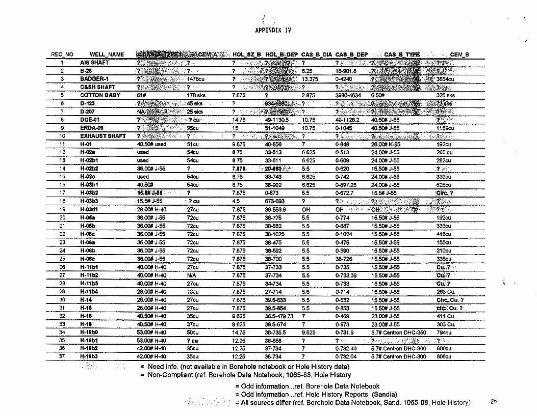
Appendix IV contains a list of boreholes within the L WB (P-18 outside of the L WB was added) that were examined during this study. This list is composed of seventy-four boreholes, all of which penetrate at least two aquifers (see also Appendix I - Map).
3.4 Examples of Potential Problem Wells
11-23S-31E - Devon Barkley #7: Good bond 150' down into the Bell Canyon Formation (perforation zone in the Yates #1 AIT Federal). 275' Poor bond at the Base of Castile Formation. Little or no bond between surface and 275' above the base of the Castile Formation
26-23S-31E - Devonffexas American Todd 26 F #3: In past literature this well was suspected to have a poor cement job and may have contaminated ground water zones with injection fluids. Records indicate a solid cemented interval through the salt section. There have, however, been problems with the 4 1/2" casing in the Rustler Formation. On November 22, 1993, the operator replaced eight joints of new casing at 338' and cemented to surface with 123 sacks of cement. This well represents what could happen to a well that reportedly cemented per OCD regulations.
8

NMED/DOE/ AIP-96/3/96Bore.kem
5-23S-31E - Grace #1 Cabin Baby Federal: Suspected bridge plug failure
3.5 Contractor Summary
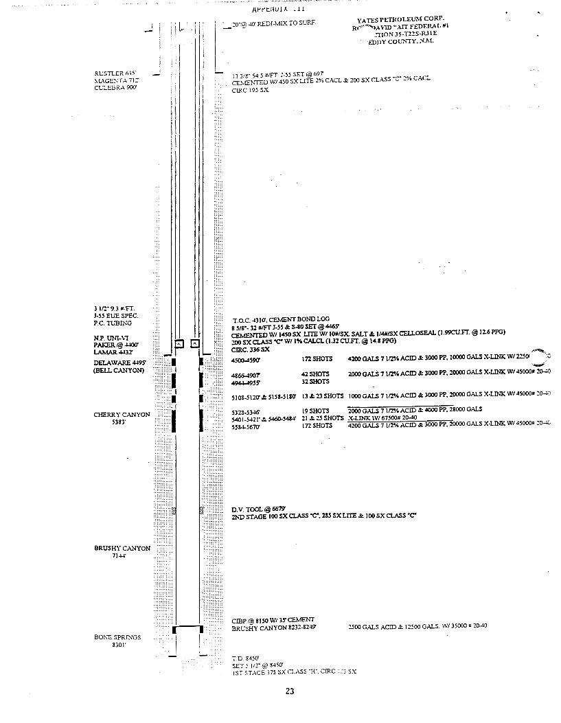
35-22E-31E - Yates #1 AIT Ross Federal: This well has been studied by the operator and Pecos Petroleum Engineering, Inc. It is a focal point due to its location 3/4 mile SE of the L WB and because it is injecting produced water into the Delaware Formation. Stakeholder concern led to the investigation of whether this injection water was the source of fluid level rise in P-18 and other wells within the WIPP boundary. Well integrity investigation shows 8 5/8" intermediate casing was set to 4465' with 1650 sacks of cement. Cement was circulated to the surface. 5 1/2" production casing was cemented to 4 31 O' or 112' above the top of the Delaware Formation, which provides 155' of cement overlap into the 8 5/8" intermediate casing (see wellbore diagram Appendix III). Calculations of induced fracture geometry suggest vertical or horizontal magnitudes of 150-200'. The ability of the Bell Canyon and Cherry Canyon intervals to accept injected fluids was calculated using compressibility formulas assuming no oil or gas is present in the injection interval. These calculations suggest that an area of less than 1,000 acres could receive this volume of water.
EPA recommended that Yates conduct a tracer survey to determine if injection fluids were "going out of zone". While this test has limited resolution of vertical movement behind pipe, it is the most defensible technology to trace what zone the produced water is entering. Before this test was run induced vertical fracture calculations indicated that frac height could exceed the Top of Cement (TOC) at 4 31 O'. The tracer test indicates that all of the injected water is entering the Delaware formation and that the top perforations 4500-90' are not receiving any fluid at all. A letter from Mr. Fant, Yates Petroleum Co., to the OCD dated December 5, 1995, indicated two build-up periods as proof of hydraulic connection between the Magenta and the Culebra as the reason for the P-18 water level increase. The two apparent build-ups are due to replacing the 4" monitoring casing with 2 3/8" tubing. The hydraulic connection assumption is in error since the well has never been perforated in the Magenta and the cement was circulated to surface behind the casing. The increasing water levels in 71 % of the thirty five wells measured in the WIPP Site area is why EPA and not NMED wanted further proof that the Yates injection well is not contributing to this problem. The tracer survey was advised to protect Yates and the general public from this issue resurfacing in the future. So the question on P-18 remains: Why is the ground water head still rising above Culebra static levels?
9
NMED/DOE/ AIP-96/3/96Bore.kem
Calculations conclude that this well has adequate mechanical integrity, is properly equipped for water disposal, and shows no indications that water is migrating from the injection zones to other zones in the well bore. The injected reservoir is of the proper nature and has sufficient volume to provide adequate storage volume for the injected fluids. · EPA suggested that the OCD require Yates to run a tracer survey as additional proof. The results of this survey revealed no vertical migration of fluids. Current technology and evaluation methods suggests that this well is compliant and disposing of water properly.
3.6 Borehole Integrity Tool Limitations
Borehole integrity tools are limited to cement bond logs and tracer surveys. The cement bond log lacks consistency to allow it to be comparable from well to well. For instance, the frequency, gating and bias levels are decided by each individual service company, and these have considerable affect on bond log response. Tracer surveys have limited horizontal resolution not to exceed 2-3' away from the wellbore. These tools, however, are the current technology and the only solution to evaluate borehole integrity.
4 .0 BOREHOLE INTEGRITY EVALUATION-TEST WELLS WITHIN THE LAND WITHDRAWAL BOUNDARY
4.1 Regulations (Boreholes and Shafts)
The following State Engineer Rules and Regulations apply to boreholes penetrating aquifers: 4-20 Test or Exploratory Wells - All test or exploratory wells shall be so constructed, maintained, and operated that each water shall be confined to the aquifer in which it is encountered. All test or exploratory wells penetrating artesian aquifers shall be cased, cemented, and tested as required for the construction of artesian wells (Article 4-15 through 4-19) and the casing shall be landed in the formation underlying the deepest artesian aquifer and cemented through all known artesian aquifers. The casing, as referred to in the artesian well specifications, is designated as the water protection string by the oil industry. If conductor pipe is used, it shall not be removed until after cementing of the casing has been completed. All casing, cementing, and testing programs shall be witnessed and approved by a representative of the State Engineer.
4-20.2 Abandonment--Plugging - In the event that the test or exploratory well is to be abandoned, the State engineer shall be notified. Such well shall be plugged in accordance with Article 4-19.l so that the fluids will be permanently confined to the specific strata in which they were originally encountered.
Note: This study did not focus on the integrity of the shafts at the WIPP site. This should be evaluated at a later date, especially in light of the State Engineer determination dated September 1996. This determination states that shafts are considered boreholes and that it is necessary to confine ground waters to the zone in which they are encountered.
4.2 List of Boreholes and Area of Study
10
NMED/DOE/ AIP-96/3/96Bore.kem
The primary focus of this investigation was the seventy-four boreholes listed in Appendix IV. The area of study was confined to the Land Withdrawal Boundary with the exception of the contractor reports which investigated the industry standard surrounding WIPP and P-18. The L WB is within the Carlsbad Basin as designated by the State Engineer.
4.3 Examples of Problem Wells
The following wells contain monitoring, maintenance or potential compliance problems in addition to the wells in Appendix V:
20-22S-31E - B-25: Water inflow while drilling from 690-70 l '. Hole size, casing and cement information are needed to calculate whether this water has been isolated.
28-22S-31E - DOE #1: No bond at the base of the intermediate casing (1130'). Cement volumes and casing information are needed to verify a suspected collapsed casing in lower hole. Culebra is known to have double porosity.
20-22S-31E - ERDA-9: The Salado is uncemented in this hole from 1045-2425'. This is the repository level and the zone of stored waste. This well is less than 40' from the E-300 drift.
20-22S-31E- WQSP #1: The Magenta Aquifer is sealed with bentonite clay from 550'-640'. Sand and gravel separate the bentonite clay plug and the Culebra. Consideration should be given to sealing the Magenta with cement to isolate the Magenta and Culebra ground water per State Engineer Regulations. At the very least, a variance should be obtained if DOE can demonstrate that the bentonite plug is less permeable than cement.
20-22S-31E - H-16: This well is mentioned in Appendix V and is significant enough to list as a problem well. This borehole allows the Dewey Lake, Magenta, Culebra, and Salado to be commingled. If contaminated waste migrates along a zone in the Salado (i.e. MB 139) and reaches this borehole (located next to the Air Intake Shaft) then it will likely contaminate all of the shallow water aquifers since they are not isolated or confined.
4.4 Borehole Sealing
11
NMED/DOE/ AIP-96/3/96Bore.kem
The best method of short term seals for boreholes was detailed in SAND84-1057. This reports states "Before plugging, existing casing should be removed whi:::re seals are to be em placed. Over long periods of time, iron casing could corrode, leaving a more permeable conduit through the plug. Further, casing cement should be removed to reestablish contact of the host rock with the new plugging material. The BCT 1-F mix or-a comparable cement should be placed in the salt zones to preclude dissolution of the: host rock by the cement water. On the other hand, the freshwater mix, BCTl-FF, is preferred in non-salt zones because of its slightly better performance characteristics (ref. Tremper 1966)."
OCD Rule-111-P (applies to all oil and gas wells in sections 27-34-22S-31 E) gives a higher standard for sealing oil and gas wells and could be adopted for all boreholes in the future. This rule generally provides that surface and salt protection casing strings be circulated with cement so as to fill the annulus behind the casing with cement. Casing and water shut-off tests are to be run to test the cement job for pressure leaks. Plugged wells shall provide a solid cement plug through the salt section to seal off the salt section and any water-bearing formations.
4.5 Contractor Summary
WIPP Bond Log Project: The purpose of this study was to determine the probability of hydraulic communication within the annulus between the formation and the casing using bond logs. The following information was determined in this study:
20-22S-31E - WIPP-18: Good bond is reported from TD of 1046' to 108' using the vintage of logs available on this well. Radial logging techniques have replaced this log which makes it easier to detect channeling through cement in wells that have circulated the cement to surface as the WIPP-18 reported. Zones within this well show amplitude changes which indicate poor bond; however, a closer look at those changes reveal formation density differences and therefore shows a good bond.
ERDA-9: Good bond is reported from 208-996'. There is no cement and no bond reported from 996-2540'. Hydraulic communication is probable through this interval.
H-1: There is bond present between 654-798'. There is no certainty of hydraulic isolation from 0-754'. This well is definitely a candidate for additional evaluation in spite of hole history reports of cement circulated to surface.
12
NMED/DOE/ AIP-96/3/96Bore.kem
5.0 CONCLUSION
This investigation has verified available DOE borehole data and offers substantial evidence that WIPP wells could be the cause of ground water fluctuations. The review of the integrity of on site boreholes and their ability to collect in-situ ground water free from interzone contamination, has indicated 15of74 boreholes may not comply with State Engineer Regulations. Information regarding 49of74 boreholes was inconclusive. In order to eliminate boreholes as a potential pathway to the environment it is recommended that DOE contact the State Engineer Office to evaluate procedures which may be required to bring boreholes into compliance with standards. The unknown causes of ground water fluctuations and the boreholes listed in Appendix V may have an effect on the Final Safety Analysis Report and the Performance Assessment of WIPP.
Practical solutions can eliminate these boreholes from environmental concerns by addressing casing and cement problems using a multi-stage approach. The first stage should include an assessment of the suspected "non compliant" and "problem boreholes" within the L WB. This may involve defining which boreholes have confirmed aquifers ("each water shall be confined"), verifying that subsequent information is not available, and determining whether shafts are compliant. Forms and reports should be provided to the State Engineer so a determination can be made whether the plugging or construction, operation, and maintenance of the drill hole are satisfactory.
The second stage should include monitoring of all oil and gas wells within a one-mile buffer to insure that operators are complying with R-111-P.
The third stage should include drilling and completing old and new boreholes consistent with the most stringent standards set by Rule-111-P. This involves re-entering the boreholes with a workover unit, logging cement integrity, pulling old casing, pumping cement across aquifers to isolate ground water, fully cementing the salt section including the annulus space behind the casing, and separating commingled perforations. All borehole workovers should be witnessed by a representative of the State Engineer.
From a practical standpoint, some of the boreholes within the L WB could be of valuable use for monitoring sources of radionuclides. This should include a frequent broad monitoring (during and after waste receipt) of the aquifers in boreholes near the repository and near the L WB.
13
NMED/DOE/AIP-96/3/96Bore.kem
6.0 REFERENCES
Agreement-In-Principle Between the United States Department of Energy and the State of New Mexico for Environmental Oversight, Monitoring, and Emergency Response, September 1995
Background Water Quality Characterization Report for the Waste Isolation Pilot Plant, DOE/WIPP 92-013, June 1992
DOE Order 5400.5/P, Radiation Protection of the Public & Environment
Environmental Oversight and Monitoring Agreement Between the U.S. Department of Energy and the State of New Mexico, October 22, 1990
Evaluation of Mineral Resources at the Waste Isolation Pilot Plant (WIPP) Site, New Mexico Bureau of Mines & Mineral Resources, March 1995
Geological Characterization Report, WIPP Site, Southeastern NM, August 1978
New Mexico Environment Department Waste Isolation Pilot Plant Site Specific Health and Safety Plan, November 1992
New Mexico Environment Department Site Specific Work Plan for the Waste Isolation Pilot Plant, NMED/WIPP, July 1996
NMED/WIPP Environmental Monitoring and Oversight Plan (NMED/WIPP 95-001)
Post-1988 Culebra Water Levels At The WIPP Site, Rick Beauheim, Sandia, EEG Technical Workshop, June 1995
Pecos Petroleum Engineering, Inc., Ross David "AIT #1 SWD Eddy County, NM, September 1995
Rules and Regulations Governing Drilling of Wells and Appropriation and Use of Ground Water in New Mexico, State Engineer, Santa Fe, New Mexico, 1995
SAND87-0039, Interpretations of Single-Well Hydraulic Tests Conducted At and Near the Waste Isolation Pilot Plant (WIPP) Site, 1983-1987, Richard L Beauhe:im, December 1987
14
NMED/DOE/ AIP-96/3/96Bore.kem
Site Specific Protocol for Implementation of the Agreement-In-Principle, NMED/WIPP, April, 1996
State Engineer Letter to Keith McKarney, June 13, 1996
State Engineer Letter to Keith McKarney, September 18, 1996
State of New Mexico Energy Minerals and Natural Resources Department Oil Conservation Division Rules and Regulations, March 1991
Stormont, J. C. 1984. Plugging and Sealing Program for the Waste Isolation Pilot Plant (WIPP). SAND84-1057. Albuquerque, NM: Sandia National Laboratories.
Tremper, B., "Corrosion of Reinforcing Steel," Significance of Tests and Properties of Concrete and Concrete-Making Materials, ASTM Special Technical Publication No. 169-A (Philadelphia, PA: ASTM, 1966).
WIPP Bond Log Project, Dean Jackson, August 1996
Waste Isolation Pilot Plant Site Environmental Report for Calendar Year 1991, DOE/WIPP 92-007
WIPP Environmental Monitoring Plan (EMP), DOE/WIPP 94-024
15
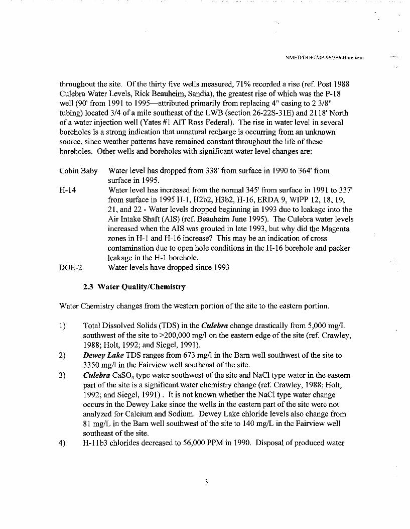
APPENDIX I
lhP-13 T-22-S R-31-E H-6a P-21 H-6b u 0 H-6c
0 SMith \JindMllls H-So ClD H-Sb
H-Sc
18 0 17 16 15 'w'IPP-13
-<>-0 llQSP-2 Badger Ill
P-5
~ \o/QSP-3
~. 'WIPP-12 n
p 1-376 u\o/QSP-1 ~ I-377
'w'!PP-18 <P
'WIPP-19
19 20 <D 21 22 <D \o/IPP-22
D-207 0 H-16 ~~~~t( D ll!PP-21
AIR Intake @ @ Shaft B-25 ~ ~ O Exhaust I-456
P~3 ~~::: O Shaft
0 ERDA-9 ~
0 h P-2
I-374 0 H-1 H-2A
H-2bl H-2b2 H-2c
P-6
30 29 28 27 0
\o/QSP-6a H-3bl O H-19b0 \o/QSP-4
~\o/QSP-6 H-3b2 H-19bl 0 H-3b3 H-19b2 0 H-3dl H-19b3
H-19b4 H-14 \o/QSP-5 H-19b5
DOE-I l-457 () P-1 0 H-19b6 P-4 H-15
H-19b7 0 o n 0 ~·
0 1-375
31 32 33 34 0
H-llbl D-l2
H-!lb2 -<>-H-llb3
0 Cotton Baby H-!lb4 111
P-9
P-15
0
WIPP LAND WITHDRAWAL BOUNDARY
K(IHl ( ~KAHfY B-C''_+-''16
SCALE 0 330'
~ 1980'
20

APPENDIX II
-----------------
·------ -·----------
_______________________________________ .. _ .. ..---... ______ _
-----------------------------------------------------------
~~==========::::::::=======----====
Santa Rosa -- Triassic
~-1-~
Dewe Lake - Permian
Rustler
Salado
Castile
- Permian
- Permian
D D
D D I I
Tops ERDA-9
- Permian -------. ·---------------------
21
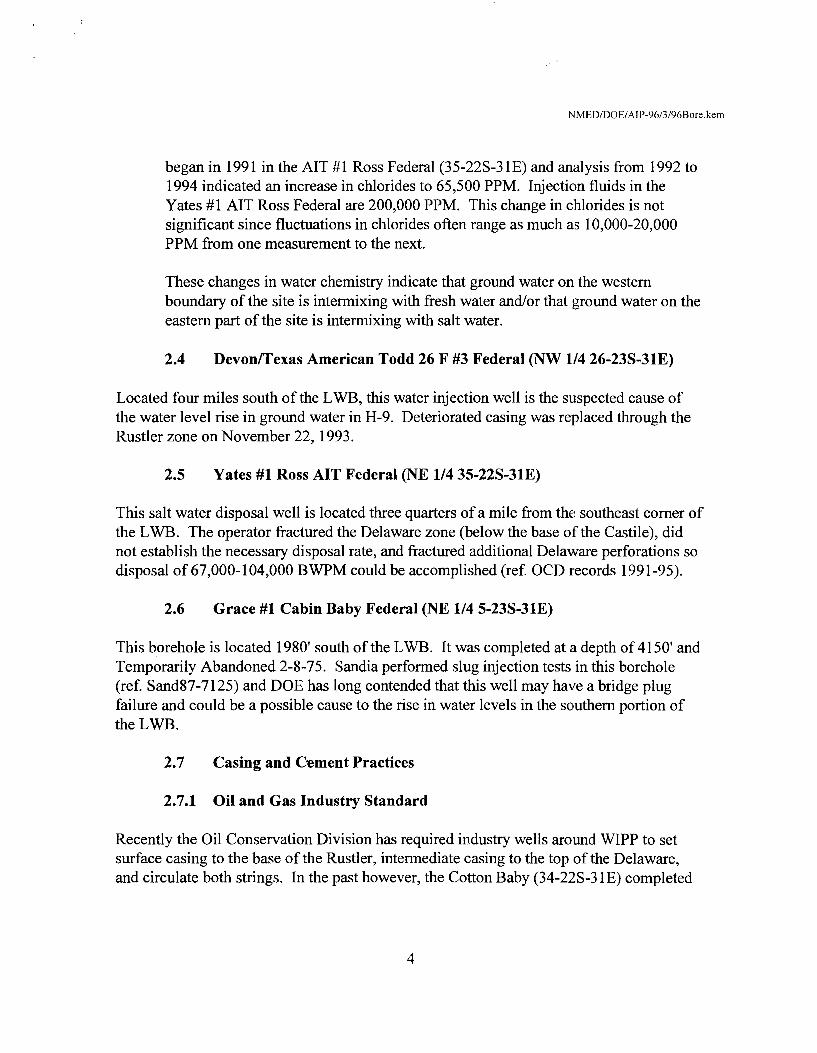
APPENDIX III -------------::·,,, _______________ .. ,,.,
o 2: Cl'.) -~ ~ - ~ '\J
::i ...J
"W 0 > •T - ul > . ~ --<C :::> Cl) Cl)
~ ~ > <C ~ :;:/) :I')
0 ~ -
Ul !--<
;2
~ >-d ....
CIJ ~ Cf.I
~ .. 0 il.. ~
• ~
....
rll ...l CD CD
~ l!! ...l 0 0 .... = > ·- Ul ~>
i=
~ ~ u
L_ ____ _l _____ _L _____ _.!!!t:::::======~-----~~==========-~~ 0
0 0
"' 0 0 0 -
ISd ''.'.raflSSffiid ::r:ivnms
0 0 VI
0
Rt:STI.ER 635' ~1.AGE:\"TA 11:· CU.EB RA 900'
3 112· 9.3 #.'FT. J.55 Eu"E SPEC. P.C. TIJBING
N.P. UNJ.\1 PAKER I@ +WO' LAMAR.:i:.i;x DELAWARE 4495' (BELL CANYON)
BRUSHY CANYON 7144'
BONE SPRP.-/GS 8301'
tr : I ,
......
.... .... ········.
n I
I
Al-'t'tNU!A 111
:o·i<? -W' REDJ-MIX TO SURF. YA TES PETROLEUM CORP
RP'""~A YID "AlT FEDERAL #I _!ION J5-TI2S-R.31 E
EDDY coUNTY.N.l\i.
13 31g· 54 5 #!FT. J-55 SET@ 697 CEMENTED WI 450 SX LITE 2% CACL & 200 SX CLASS ·c· :% CACL
CIRC 195 SX.
T.O.C. -n!O'. CEMENT BOND LOG 8 518"· 32 #IFT 1-SS &: S-80 SET@ 4465' CEMENTED WI 1450 SX LITE W/ 10#/SX. SALT&: 1/4#/SX CELLOSEAL (l.99CU.FT.@ 12.6 PPG) 200 SXCLASS •c- WI 1%CALCL(l.32CU.Fr.@ 14.SPPG)
CIRC.336SX ,.,,..,.,, 45004590' 172SHOTS 4200 GALS 7112"/o ACID&: 3000 PP, 10000 GALS X·l.INK WI l:SOI -.'.l
4866-4907 4944-4955'
42SHOTS 32SHOTS
··-· 2000 GALS 7 112% ACID&: 3000 PP. :?0000 GALS X-LINK WI 45000# 20..:.~
SIOS-5120' .f: 5158-5130' 13 & 23 SHOTS 1000 GALS 7 112"/o ACID&: 3000 PP. 20000 GALS X-LINK W/ 45000# :o..:.~
5323-5346' 19 SHOTS 2000 GALS 7 112"/• ACID & 4000 PP, 28000 GALS 5401-5421'&5460-5484' 21 &25SHOTS X-LINKWl67500#20-40 5584-5610' 172 SHOTS 4200 GALS 7 1/2% ACID&: 3000 PP. 20000 GALS X-LINK WI 45000# :o..:v
D.V. TOOL@ 6679' 2ND STAGE 100 SX CLASS "C". 285 SXLITE & 100 SX CLASS "C"
CIBP !@ 8150 WI 35' CEMENT BRUSHY CANYON 8232-8249'
TD. 8450'
2500 GALS ACID & 12500 GALS. WI 35000 # 20~
SET 5 1/2" fa) 845CY !ST STAGE-375 SX CLASS "H". CIRC : :3 SX
23

APPEmJIX IV
REC NO WELL_NAME WELL_NO SEC_T_R CAS_ELEV BDB_LOC BDB_ELEV TD COMP _DATE CEMENT .lrf<f'-~~g~~_AS_A_DIA CAS_A_DEP., 1 AIS SHAFT W/111 20-22S-31E ? 1025.2'F5L-1204'FEL ? ? ? ? ? .? .· 1 ?
2 B-25 \NN2 20-225-31E 3408.19 796.0'F5L-777.0'FEL 3408.74 901.8 01/18179 ? 11 -ti:-. 9.625 0-18 3 BADGER-1 WW3 15-22S-31 E 3496 KB 1980.0'F5L-1980.0'FWL 3496.00 15225 11 /17173 0-11990 ? 0-804 20 0-804
4 C&5H SHAFT WN4 20-225-31 E ? 1025.2'F5L-579.1 'FEL 3411.00 ? ? ? ? ? 'J ?
5 COTION BABY WN5 34-22S-31E 3455 KB 1980'F5L-1980'FWL 3445.00 6651 12115175 ref. plugs 15 :?- 13.375 0-680.76
6 D-123 \NN6 34-22$-31 E ? ? 3432.00 1880 08/07/53 692-880 6.25 :0.934 ; ' ..• :. 4 692-880
7 D-207 WW7 19-22S-31 E ? ? 3406.00 1613 07/03/58 0-470 ? }? · Pulled O
8 DOE-01 WN8 28-22S-31E 3485.22 182.4'F5L-607.8'FEL 3485.22 4057.3 07/28/82 0-1123 >20? . 0-49 20 0-49
9 ERDA-09 WN9 20-225-31E 3410.10 267.17'FSL-176.74'FEL 3410.10 2886 06/26176 2426-2883 20 5-40 16 0-40
10 EXHAUST SHAFT WN10 20-22S-31E ? 625.2'F5L-103.6'FEL 3409.90 ? ? ? ? ? ? ?
11 H-01 WN11 29-225-31 E 3399.53 623.2'FNL-1083.1'FWL 3399.53 856 06/10176 0-848 18 0-40 10.125 0-48 12 H-02a WN12 29-22S-31E 3378.09 726.86'FNL-1697.64'FWL 3378.09 654 02/21177 0-513 18 4-33 10.75 0-33
13 H-02b1 WN13 29-22S-31E 3378.46 69U7.FNL-1660.57'FWL 3378.48 661 02/14177 0-609 18 4-33 1 0. 75 0-33
14 H-02b2 WN14 29-22$-31 E 3378.31 700.S'FNL-1690.B'FWL 3378.31 649 05/03/84 ? 18" J)•20' 9.625 0-20
15 H-02c WN15 29-22S-31E 3378.41 637.15'FNL-1708.62'FWL 3378.41 795 02/05177 0-742 18 4-33 10.75 0-33
16 H-03b1 WN16 29-22S-31E 3390.64 2086.31'FSL-138.10'FEL 3390.64 902 08/12176 0-891 13.75 0-38 10.75 0-38
17 H-03b2 W/1117 29-225-31E 3390.03 2122.15'FSL-231.29'FEL 3390.03 725 11/14/83 0-672.7? ? 0-34 ? ?
18 H-03b3 W/1118 29-22S-31E 3388.67 2022.35'FSL-217.30'FEL 3388.67 693 01/30/84 50-670.S? 7.875 0-673 5.5 .50-670.5
19 H-03d1 W/1119 29-22S-31E 3390.01 2067.3'F5L-164.3'FEL 3390.01 554 04/22/87 0-39 12.25 0-39 8.625 0-39
20 H-05a \NN20 15-22$-31 E 3506.44 1091.98'FNL-185.03'FEL 3506.19 930 06/20178 0-774 18 5-38 9.625 0-38
21 H-05b \NN21 15-22S-31E 3506.04 1008.30'FNL-236.22'FEL 3506.04 925 06/13178 0-887 18 5-38 9.625 0-36
22 H-05c \NN22 15-22S-31E 3506.04 1006.55'FNL-134.95'FEL 3506.04 1076 06/03178 0-1024 18 5-38 9.625 0-38
23 H-06a \NN23 18-22S-31E 3347.83 283.30'FNL-274.34'FWL 3347.83 637 07/11178 0-476 18 5-38 9.625 0-38
24 H-06b \NN24 18-22S-31E 3348.25 j96;34'FNL·332;96'FWL::\:0' 3348.25 640 07/05178 0-590 18 5-38 9.625 0-38
25 H-06c \NN25 18-22S-31E 3348.52 281.06'FNL-374.47'FWL 3348.52 741 06/26178 0-699 18 5-38 9.625 0-38
26 H-11b1 \NN26 33-22$-31 E 3411.62 1510.9'FSL-173.9'FEL 3411.62 785 09/02183 0-735? 18 0-37 9.625 0-35
27 H-11b2 \NN27 33-22S-31E 3411.64 1436.3'F5L-168.7'FEL 3411.64 776 11/28/83 0-733.39? 18 0-37 9.625 0-37 28 H-11b3 \NN28 33-225-31E 3412.42 1501.7'FSL-105.2'FEL 3412.42 788.7 01/84 0-734? 18 0-37 9.625 0-34 (
29 H-11b4 \NN29 33-22S-31E 3410.89 1514.7'FSL-320.2'FEL 3410.89 765 03/15/88 0-714 16 0-27 8.625 0-27 '\
30 H-14 WWJO 29-22$-31 E 3347.11 372.2'F5L-562.4'FWL 3347.11 589 10/23/86 0-532? 12.25 0-39.5 8.625 0-39
31 H-15 WW31 28-22S-31 E 3481.63 88.7'FSL-174.3'FEL 3481.63 900 11/14/86 0-853? 12.25 0-39.5 8.625 0-39
32 H-16 WW32 20-22S-31E 3406.77 1112.6'FSL-1241.3'FEL 3406.77 850.9 08/18/87 0-469 18 0-36.5 10.75 0-36.5 33 H-18 WW33 20-22S-31E 3414.21 964.B'FNL-445.6'FWL 3414.21 840 11/16/87 0-673 18 0-39.5 10.75 0-39.5
34 H-19b0 WW34 28-225-31 E 3418.38 1484.8'FSL-2480.4'FVVL 3417.11 778.7 04/23/95 0-731.9 24 0-38 20 0-38
35 H-19b1 WW35 28-22S-31E ? 1535.0'F5L-2460.8'FVVL 3417.43 732.6 03/19/95 NIA 24 0-38 20 0-38 36 H-19b2 WW36 28-22S-31E 3419.01 1434.3'F5L-2459.6'FVVL 3417.13 785.4 08/28/95 0-732.4 18 0-37 14 0-37
37 H-19b3 WW37 28-22S-31E 3419.09 1509.2'F5L-2503.9'FVVL 3417.28 785 08/29/95 0-734.0 18 0-38 14 0-38
Updated 9-3-96
= Need info. (not available in Borehole notebook or Hole History data) = Non-Compliant (ref. Borehole Data Notebook, 1065-88, Hole History
=Odd information ... ref. Borehole Data Notebook =Odd information ... ref. Hole History Reports (Sandia) =All sources differ (ref. Borehole Data Notebook, Sand. 1065-88, Hole History) 24

APPENDIX IV
REC NO WELL NAME WELL_NO SEC_T_R CAS_ELEV BOB LOC BDB_ELEV TD
38 H-19b4 VWl/38 28-22S-31E 3419.03 1510.6'FSL-2417.1'FWL 3417.03 781.5 39 H-19b5 VWl/39 28-225-31 E 3418.63 1466.3'FSL-2420.4'FWL 3416.89 783.4 40 H-19b6 WN40 28-225-31 E 3419.07 1554.4'FSL-2472.6'FWL 3417.25 785 41 H-19b7 WN41 28-22S-31E 3418.99 1455.6'FSL-2464.1'FWL 3416.94 785 42 1-374 WN42 30-225-31 E ? 424.0'FNL-45.0'FWL 3340.00 1538
43 1-375 WN43 33-225-31 E ? 144.0'FNL-24.0'FWL 3390.00 1746
44 1-376 WN44 20-225-31 E ? 400.0'FNL-75.0'FWL 3410.00 1702
45 1-377 WN45 22·22S-31E ? 105.01'FNL-48.0'FWL 3490.00 1876
46 1-456 IJINl/46 22-225-31 E ? 300.0'FSL-2650.0'FEL 3520.00 1975 47 1-457 WN47 27-225-31 E ? 200.0'FSL-1200.0'FWL 3460.00 1885 48 P-01 WN48 29-225-31 E ? 327.0'FSL-551.0'FWL 3345.00 1200
49 P-02 WN49 28-22S-31E ? 125.0'FNL-172.0'FEL 3478.00 1895 50 P-03 WVl/50 20-225-31 E ? 103.0'FSL-3122.0'FEL 3382.00 1676 51 P-04 1/1/1/1151 28-225-31 E ? 146.0'FSL-1487.0'FEL 3441.00 1857
52 P-05 WVl/52 17-225-31 E ? 202.0'FSL-165.0'FEL 3472.00 1420 53 P-06 WVl/53 30-22S-31E ? 2767.0'FSL-199.0'FWL 3354.00 1573
54 P-09 WVl/54 33-22S-31E ? 1493.0'FSL-143.0'FEL 3409.00 1796
55 P-13 WVl/55 18-22S-31E ? 125.0'FNL-116.0'FWL 3345.00 1576
56 P-15 WVl/56 31·22S~1E ? 410.8'FSL-192.32'FWL 3309.70 1465
57 P-18 WVl/57 26-225-31 E ? 138.5'FSL-732.7'FEL 3479.00 1998 58 P-21 WVl/58 15-22S-31E ? 852.0'FNL-150.0'FEL 3510.00 1915
59 SMITH WINDMILL WVl/59 15-225-31E 3454.70 819'FWL-1547'FNL ? 161
60 SMITH WINDMILL Vl/Vl/60 15-22S-31E 3456.60 905'FWL-1547'FNL ? 169 61 WASTE SHAFT Vl/Vl/61 20-225-31 E ? 625.2'FSL-554.1 'FEL 3409.00 ?
62 WIPP-12 Vl/Vl/62 17·225-31E 3472.06 149.4'FSL-80.4'FEL 3472.06 3927.6 63 WIPP-13 Vl/Vl/63 17-225-31 E 3405.71 2585.68'FSL-1730.59'FWL 2585.68 3868 64 WIPP-18 Vl/Vl/64 20-225-31 E 3458.76 983.58'FNL-11.85'FEL 3458.70 1060
65 WIPP-19 Vl/Vl/65 20-225-31E 3435.14 2288.5'FNL-12.7'FEL 3435.14 1038 66 WIPP-21 Vl/Vl/66 20-225-31 E 3418.96 1450.6'FSL-11.7'FEL 3418.96 1045 67 WIPP-22 Vl/Vl/67 20-225-31 E 3428.12 2544.9'FSL-10.82'FEL 3428.12 1450 68 WQSP-01 Vl/Vl/68 20-225-31 E ? 101.0'FNL-1422.0'FWL 3575.00 737 69 WQSP-02 Vl/Vl/69 16-225-31 E ? 1646.0'FSL-142.0'FWL 3400.00 846 70 WQSP-03 WN70 16-225-31E ? 96.0'FSL-2162.0'FEL NIA 879 71 WQ5P-04 WN71 28-225-31 E ? 1632.0'FSL-2136.0'FEL NIA 800 72 WQSP-05 WN72 29-225-31 E ? 300.0'F5L-340.0'FEL NIA 681 73 WQSP-06 WN73 29-22$-31 E ? 1626.0'FSL-1461.0'FWL 3350.00 617 74 WQSP-06a WN74 29-225-31E ? 1653.0'FSL-1395.0'FWL NIA 225
= Need info. (not available in Borehole notebook or Hole History data) = Non-Compliant (ref. Borehole Data Notebook, 1065-88, Hole History
Updated 9-3-96 = Odd information ... ref. Borehole Data Notebook
COMP _DATE CEMENT ,'fldL;;;.$~l~~-OLl'AQ~iqAS_A_DIA CAS_A_DEP 08/22/95 0-736. 7 18 0-38 14 0-38 08/26195 0-734.0 18 0-38 14 0-38 08/24/95 0-733.0 18 0-39 14 0-39
08/19/95 0-734.0 18 0-38 14 0-38
04/27/65 ? 6.25 0-714 4 437-714
05/13/65 ? 6.25 0-520 4 129-817
06/23/65 ? 6.25 0-840 pulled 0
07/16165 ? 6.25 .0-996 pulled 0
NIA ? 6.25 0-940 pulled 0
NIA ? 6.25 0-940 pulled 0
09/02176 0-1591 8.75 0-32 0 0
09/02176 ? -1895 8.75 0-20 0 0
09/07176 0-1676 8.75 0-30 0 0
09/04176 0-1857 8.75 0-23 0 0
09/21176 0-1830 8.75 0-25 0 0
09/16/76 0 -1573 8.75 0-18 0 0
09/25/76 0 -1796 8.75 0-23 0 0
09/23/76 0 -1576 8.75 0-18 0 0
10/14176 0-1465 8.75 0-20 8.625 0-20
11105/76 0-1998 8.75 0-18 8.625 0-18
10/26/76 0 -1915 8.75 0-23 0 0
02/19159 ? ·? ? 6.625 7
02/19/59 ? ? ? 12.75 ?
N/A ? ? ? 4 ?
12107178 0-1015 18 4-38.6 ·13.375 4-38.6
10/05/79 0-1035 16 5-36 13.375 0-35.5
04/03/78 0 8.75 0-16 7 0-16
05/08/78 0 8.75 0-8 7 0-8
05/26178 0 8.75 0-15 7 0-15
05124178 0 8.75 0-20 7 0-20
09/16/94 0-550 15 0-25 10.75 0-25
09/10/94 1-770 15 0-25 10.75 0-25
10/26194 0-800? 15 0-25 10.75 0-25
10107194 ? 15 0-25 10.75 0-25
10/13/94 1-613 15 0-25 10.75 0-25
09/30/94 1-560 15 0-25 10.75 0-25
10/31194 0-152 15 0-25 10.75 0-25
= Odd information ... ref. Hole History Reports (Sandia) =All sources differ (ref. Borehci lata Notebook, Sand. 1065-88, Hole History) 25
REC NO WELL NAME 1 AISSHAFT 2 B-25 3 BADGER-1 4 C&SHSHAFT 5 COTTON BABY 6 D-123 7 D-207 8 DOE-01 9 ERDA-09 10 EXHAUST SHAFT 11 H-01 12 H-02a 13 H-02b1 14 H-02b2 15 H-02c 16 H-03b1 17 H-03b2 18 H-03b3 19 H-03d1 20 H-06a 21 H-06b 22 H-05c 23 H-06a 24 H-06b 25 H-08c 26 H-11b1 27 H-11b2 28 H-11b3 29 H-11b4 30 H-14 31 H-15 32 H-16 33 H-18 34 H-19b0 35 H-19b1 36 H-19b2 37 H-19b3
<,
APPENDIX IV
~~c~~~;;,:; HOL_sz ... a HOt.;;.EiiDEP CAS_B_DIA CAS.-B_DEP CEM_B ? .• ·:<.::<.."?·:~~~)~'l« -? ? ', ·;,\;;_;)~;l't~~~<i:' 6.25
1478cu ? 13.375
61# 170 sks 7.875 ? 2.875 3980-4634 6.50#
,?;$:?-J,i~t~~{.~y,>:c:::-4ifaks ? ~Af~~~~r}~_;'f~''i;F. 25 sks ? ,-
1:!:'..:~lif:'-~Zfr~JF . . -?cu 14.75 49-1130.5 10.75 49-1126.2 40.SO#J-55 :.r!t~·,:'. '?;S,~~~;:\i@:<~ ··· 95cu 15 51-1049 10.75 0-1045 40.SO#J-55 1159cu '.L~~~j~•;;.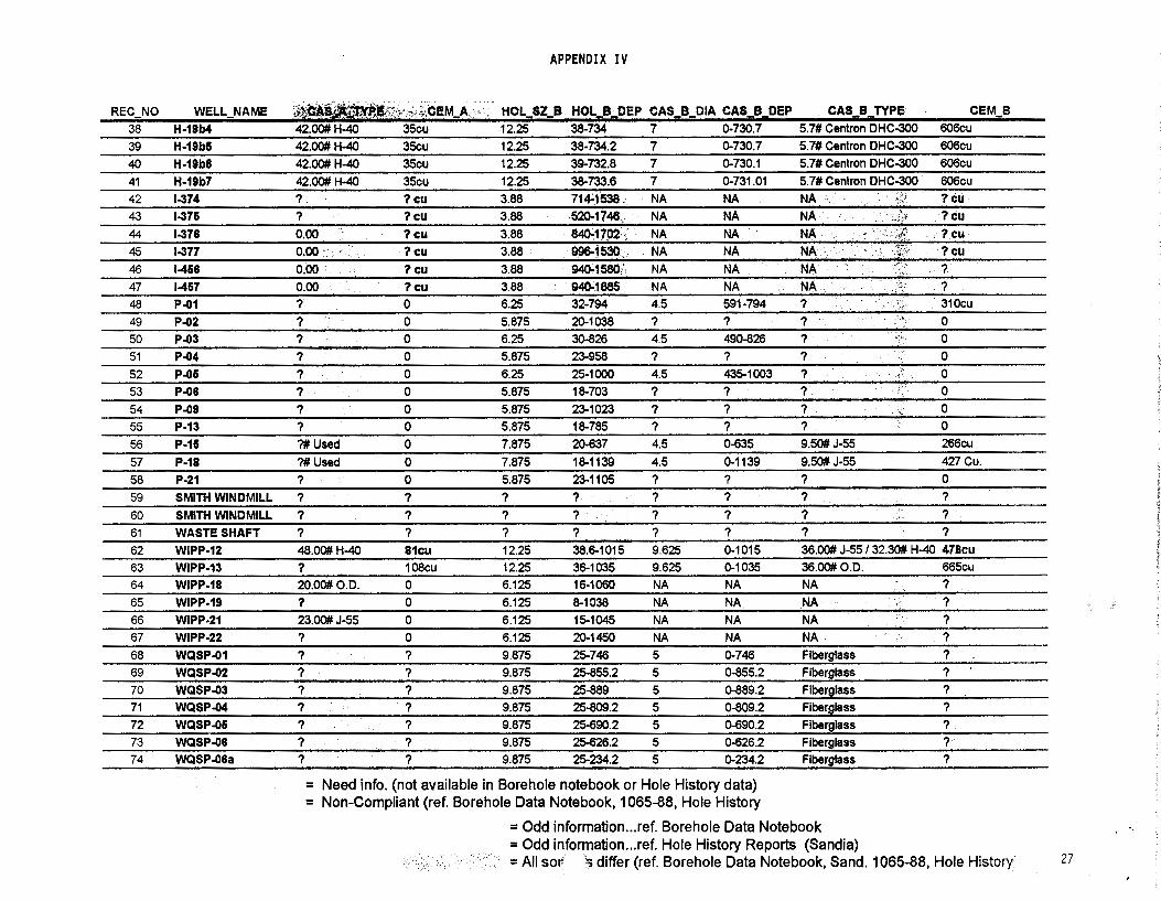
APPENDIX IV
REC_NO WELL_NAME ~'t~~~~-g,st:~fr.~;CJ;M_A _ _' :· HOL_sz_B -HOL_!l~Ef' CAS_f!_DIA C~B_DEP CAS_B_TYPE CEM_B 38 H-19b4 42.00# H-40 35cu 12.25 38-734 7 0-730.7 5.7# Centron DHC-300 606cu
39 H-19b6 42.00# H-40 35cu 12.25 38-734.2 7 0-730.7 5.7# Centron DHC-300 606cu
40
41
42
43
44
45
46
47
48
49
50
51
52
53
54
55
56
57
58
59
60
61
62
63
64
65
66
67
68
69
70
71
72
73
74
H-19b8 42.00# H-40 35cu 12.25
H-19b7 42.00# H-40 35cu 12.25
1-374 ? ?cu 3.88
1-376 ? ?cu 3.88
1-378 0.00 ?cu 3.88
1-377 0.00 .• ?cu 3.88 1-468 0.00 ?cu 3.88
1-467 0.00 ?cu 3.88
P..01 ? 0 6.25
P..02 ? 0 5.875
P..03 ? 0 6.25
P..04 ? 0 5.875
P..06 ? 0 6.25
P..08 ? 0 5.875
P..09 ? 0 5.875
P-13 ? 0 5.875
P-16 ?#Used 0 7.875
P-18 ?#Used 0 7.875
P-21 ? 0 5.875
SMITH WINDMILL ? ? ? SMITH WINDMILL ? ? ? WASTE SHAFT ? ? ?
WIPP-12 48.00# H-40 81cu 12.25
WIPP-13 ? 108cu 12.25
WIPP-18 20.00#0.D. 0 6.125
WIPP-19 ? 0 6.125
WIPP-21 23.00# J-55 0 6.125
WIPP-22 ? 0 6.125
WQSP..01 ? ? 9.875
WQSP..02 ? ? 9.875
WQSP..03 ? ? 9.875
WQSP..04 ? ? 9.875
WQSP..06 ? ? 9.875
WQSP..08 ? ? 9.875
WQSP..08a ? ? 9.875
39-732.8 7 0-730.1
38-733.6 7 0-731.01
71~1538: NA NA 520-1146. . NA NA s.ro.;1702 ': NA NA 996-1530 . . NA NA 940-1580! NA NA 940-1885 . NA NA 32-794 4.5 591-794
20-1038 ? ? 30-826 4.5 490-826
23-958 ? ?
25-1000 4.5 435-1003
18-703 ? ? 23-1023 7 ? 18-785 ? ? 20-637 4.5 0-635
18-1139 4.5 0-1139
23-1105 ? ?
? ? ?
? ? 7
? 7 ?
38.6-1015 9.625 0-1015
36-1035 9.625 0-1035
16-1060 NA NA 8-1038 NA NA 15-1045 NA NA 20-1450 NA NA 25-746 5 0-746
25-855.2 5 0-855.2
25-889 5 0-889.2
25-809.2 5 0-809.2
25-690.2 5 0-690.2
25-626.2 5 0-626.2
25-234.2 5 0-234.2
5.7# Centron DHC-300
5.7# Centron DHC-300 NA ·. NA·· NA NA NA NA ? ? ? ? ? ? ? ? 9.50# J-55
9.50# J-55
? ? ? ?
'
.. -/·
: ;~.,
','·
~ '.
606cu
606cu
?.cu ?cu ?cu ?cu ? ? .
310cu
0 0 0
0 0
0
0 266cu
427 cu.
0 ? ? ?
36.00# J-55 / 32.30# H-40 476cu
36.00# 0.0. 665cu
NA ? NA , ?
NA ? NA ? Fiberglass ? Fiberglass 7
Fl berg lass ? Fiberglass ? Fiberglass ? Fiberglass ? Fiberglass ?
= Need info. (not available in Borehole notebook or Hole History data) = Non-Compliant (ref. Borehole Data Notebook, 1065-88, Hole History
= Odd information ... ref. Borehole Data Notebook = Odd information ... ref. Hole History Reports (Sandia) = All sor ~differ (ref. Borehole Data Notebook, Sand. 1065-88, Hole History· 27

APPENDIX IV
. . . ...... . REC_NO WELL_NAME :'.J!Qj;;-_1$,Z,~_9"«4:f0~~::;,t:)f;P;;"CASl,~CIA:CAS;'.;i:t:OJEP '· CASlC'lTI'.PE . _CEM~C DWY_LAKE MAG CUL SAL CAST
1 AIS SHAFT ? · ? ·? ? ? ::? .. ·. ,: .·· ? ? ? . ? ?
2 B-25 NA NA . :,NA NA NA . NA 45.0-533.0 592.7-617.0 704.1-728.0 842.9-901.8 NA
3 BADGER-1 12.25 4240-11990 9.625 0-11970 ? . 2640cu ? ? ? ? ?
4 C&SH SHAFT ? ? · .•? ? ? 1 . :·.;. . ? ? ? ? ?
5 COTTON BABY ?: , ? · >· ?/ · ? ? •?'.Ht·'. 80.0-575.0 652.0-682.0 732.0-774.0 970.0-2940.0 2940. 0-4320. 0 6 D-123 NA NA -.::_;·NA - NA NA --::~N/i.;:."-:· - - ? ? ·. ?- .: ?. NA
7 D-207 NA NA . NA · NA NA .'. N~.\:. ? ? _? : ? NA 8 DOE-01 7.875 1126.2-4003.6 ? ? ? ?· . 133.0-667.5 722.0-745.0 828.6-850.5 976.5-2936-5 2936.5-4057.3
9 ERDA-09 9.875 1049-2886 7 0-2889.66 23.00# J-55 122cu 63.0-550.0 608.0-632.0 716.0-739.0 860.0-2836.0 2836.0-2889.0 10 EXHAUST SHAFT ? . ? ? ? ? · ? . · ? ? . ? ?. NA
11 H-01 NA NA NA NA NA NA 35.0-502.0 563.0-589.0 676.0-699.0 824.0-856.0 NA
12 H-02a 5.75 513-625 4.5 0-623 9.50# J-55 ? 38.0-457.0 515.0-543.0 623.0-645.0 NA ~ 13 H-02b1 4.75 611-661 OH OH OH OH 38.0-457.0 515.0-543.0 623.0-645.0 NA NA.
14 H-02b2 4.75 620-649 4.5 614.3-648 ? ? 38.0-457.0 515.0-543.0 623.0-645.0 NA NA 15 H-02c 4.75 743-795 OH OH OH OH 34.0-457.0 515.0-540.0 624.0-642.0 764.0-795.0 NA 16 H-03b1 NA NA NA NA NA NA 22.0-502.0 559.0-584.0 672.0-694.0 821.0-902.0 ~IA
17 H-03b2 4.75 673-725 OH OH OH OH 65.0-565.7 564.0-590.0 676.0-700.0 NA NA 18 H-03b3 ? 693-730 OH OH OH OH ? 563.0-586.0 673.0-696.0 NA NA
19 H-03d1 NA NA NA NA NA NA 420.0 424.0-448.0 545.0-554 NA NA
20 H-05a 4.75 775-824 OH OH OH OH 225-732 783-810 897-920 NA NA
21 H-05b 4.75 881-925 OH OH OH OH 225.0-732.0 785.0-805.0 897.0-920.0 NA NA 22 H-05c 4.75 1025-1076 OH OH OH OH 225.0-732.0 788.0-812.0 899.0-924.0 1041.0-1076.0 NA
23 H-06a 4.75 475-525 OH OH OH OH 225~~~'?)\' 429-511 £.d~~t7 //·:.)NA NA
24 H-06b 4.75 592-640 OH OH OH OH 38.0-427.0 492.0-511.0 604.0-627.0 NA NA 25 H-06c 4.75 700-741 OH OH OH OH 38.0-427.0 490.0-514.0 604.0-627.0 721.0-741.0 NA
26 H-11b1 4.75 733-785 OH OH OH OH 63.0-558.0 611.0-638.0 730.0-756.0 NA NA
27 H-11b2 4.75 734-776 OH OH OH OH 62.0-560.0 618.0-644.0 733.0-757.0 NA NA 28 H-11b3 4.75 734-788.7 OH OH OH OH 59.5-560.2 616.0-644.0 734.0-759.0 NA N
29 H-11b4 4.75 715-765 OH OH OH OH 60.0-554.0 614.0-642.0 723.2-746.1 NA N' )-~~~~~~~~~~~~~~~~~~~~~~~~~~~~~~~~~~~~~~~~~~~~~~~~~~~~~~~~~~~~~-~ ~
30 H-14 4.75 533-589 OH OH OH OH 40.0-360.0 424.0-448.0 545.0-572.0 NA 31 H-15 4.75 854-900 OH OH OH OH 168.0-692.0 748.0-773.0 861.0-883.0 NA 32 H-16 6.125 469.73-850.9 OH OH OH OH 52.0-531.9 590.2-61!5.6 702.5-724.4 841.5-850.9 33 H-18 6.125 674-840 OH OH OH 20sacks 20.0-506.1 5,71.2-594.2 688.6-712.8 820.9-840.0
34 H-19b0 7.75 735.5-778.7 OH OH OH OH 53.0 ?-567.0 628.0-652.0 740.1-764.4 NA 35 H-19b1 4.835 658-732.6 OH OH OH OH 53.0 ?-567.0 625.0-650.3 740.1-7 NA
36 H-19b2 5.875 734-785.4 5.5" 764-784 3.9# PVC ? 58.0 ?-567.0 628.0-653.0 741.6-766.0? NA 37 H-19b3 5.875 734-785 5.5" 762-782 3.9# PVC ? 60.0 ?-568.0 629.0-654.0 740.0-765.0? NA
= Need info. (not available in Borehole notebook or Hole History data) = Non-Compliant (ref. Borehole Data Notebook, 1065-88, Hole History
=Odd information ... ref. Borehole Data Notebook =Odd information ... ref. Hole History Reports (Sandia)
·:·· ·.• : ~· = All sources differ (ref. Borehole Data Notebook, Sand. 1065-88, Hole History)
NA NA
NA NA
NA
NA NA NA
28
REC NO
38 39
40 41 42 43 44
45 46 47 48
49
50 51
52 53 54 55 56 57 58
59 60 61
62 63 64
65 66 67 68 69 70 71 72
73 74
APPENDIX IV
WELL NAME :~1'-()!<l$RC:1<>~.,agi;;;;;~~O):P::D,~,:;;~..:;"?_IA'.;''~:::.~.;;.o~ ,.!; CASiO~TY:PE ~~a-~_;;.c DWY _LAKE MAG H-19b4 5.875 734-781.5 5.5" 761·781 3.9# PVC ? 58.0 ?-568.0 628.0-653.0
H-19b5 5.875 734.2-783.4 ';. 5.5" 763-783 3.9#PVC ?
H-19b6 5.875 732.8-785 . "5.5" 766-786 3.9# PVC ? H-19b7 5.875 733.6-785 5.5" 764-784 3.9# PVC ? 1-374 NIA NIA ·NIA NIA NIA .. NIA·· 1-375 NIA NIA NIA NIA NIA NIA 1-376 NIA NIA .·NIA NIA NIA NIA. 1-377 NIA NIA NIA NIA NIA NIA 1-456 NIA NIA NIA NIA NIA N/A.· 1-457 NIA NIA ·NIA NIA NIA NIA P..()1 3.375 794-1200 NA NA NA 310 Cu. P-02 3.9375 1038-1895 NA NA NA 274cu P-03 3.9375 826-1676 NA NA NA 302cu
P-04 3.9375 958-1857 NA NA NA 360cu
P-05 3.875 1000-1420 NA NA NA 336cu P-06 3.9375 703-1573 NA NA NA 374cu P-09 3.9375 1023-1796 NA NA NA 410cu P-13 3.9375 785-1576 NA NA NA 338cu
P-15 4 637-1038 NA NA NA 108cu
P-18 3.875 1139-1998 NA NA NA 130cu
P-21 3.9375 1105-1915 NA NA NA 425cu SMITH WINDMILL ? ? ? ? ? ? SMITH WINDMILL ? ? ? ? ? ? WASTE SHAFT ? ? ? ? ? ? WIPP-12 7.875 1015-2790 OH OH OH OH WIPP-13 7.875 1035-3868 OH OH OH OH WIPP-18 NA NA NA NA NA NA WIPP-19 NA NA NA NA NA NA WIPP-21 NA NA NA NA NA NA WIPP-22 NA NA NA NA NA NA WQSP-01 NA NA NA NA NA NA WQSP-02 NA NA NA NA NA NA WQSP-03 NA NA NA NA NA NA WQSP-04 NA NA NA NA NA NA WQSP-05 NA NA NA NA NA NA WQSP-06 NA NA NA NA NA NA WQSP..06a NA NA NA NA NA NA
= Need info. (not available in Borehole notebook or Hole History data) = Non-Compliant (ref. Borehole Data Notebook, 1065-88, Hole History
=Odd information ... ref. Borehole Data Notebook =Odd information ... ref. Hole History Reports (Sandia)
58.0 ?-565.0 623.0-649.0 63.0 ?-566.0 623.0-649.0
60.0 ?-567.0 627.0-652.0
0-357.0 417.0-443.0 ? ?
? ? ? ? ? ?
? ? 40.0-358.0 423.0-448.0
164.0-690.0 748.0-773.0 41.0-468.0 529.0-553.0
99.0-609.0 662.0-686.0 146.0-623.0 686.0-711.0 18.0-357.0 417.0-443.0 66.0-562.0 617.0-644.0 38.0-427.0 490.0-514.0 32.0-231.0 294.0-321.0
87.0-626.0 704.0-730.0 225.0-734.0 788.0-812.0 ? ?
? ? ? ? 167.0-640.0 703.9-727.0 66.0-517.0 565.0-583.0
138.0-613.0 672.0-696.0 96.0-590.0 647.0-672.0
73.0-560.0 618.0-642.0 81.0-57 4.0 630.0-654.0
40-522 591-612 143-169 692-714 156-669 n7-749 78-588 652-672
25-475 530-554 68-409 474-497 35-220 NA
::.'~:>·:····' =All sources differ (ref. Borehole Data Notebook, Sand. 1065-88, Hole History)
CUL SAL CAST
738.5-761.8 NA NA 736.7-761.2 NA t~A
739.0-763.8? NA NA 739.5-764.0? NA NA 537.0-560.0 659.0-1538.0 NA
? '" ? ?
? ,/\ ? ? ? 1 .'.
~· .. ? ? ? ?
? ? ?
538.0-565.0 677.0-1591.0 NI).
857.0-883.0 1008.0-18950 Nl 642.0-665.0 759.0-1668.0 NA 775.0-802.0 930.0-1857.0 NA 804.0-827.0 947.0-1830.0 NA 537.0-560.0 659.0-1573.0 NA 734.0-757.0 881.0-1796.0 NA 604.0-627.0 721.0-1573.0 NA 413.0-435.0 542.0-1465.0 NA 909.0-938.0 1088.0-2000.0 NA 899.0-924.0 1043.0-1918.0 NA ? ? " • ., ?
? ?. ?
1 ? : . ?
822.0-846.8 966.0-2337.5 2337.0-3927.5
703.0-726.0 846.0-2971 2971.6-3856.0
787.0-808.0 928.0-1060.0 NA 756.0-779.0 895.0-1038 2 NA 729.0-753.0 868.0-1046.0 ij 742.0-764.0 885.0-1450.0 NA NA NA NA 811-833 NA . NA 848-811 NA . NA 770-79o NA ! NA 648-669 NA·' NA 588-606 NA NA NA NA NA
29
APPl::NOIX IV
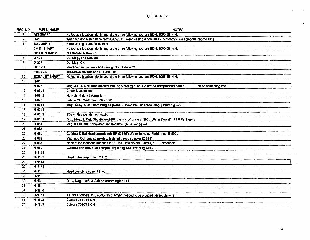
REC_NO WELL_NAME NOTES 1 AIS SHAFT No footage location info. In any of the three following sources:BDN, 1065-88, H.H. 2 B-25 wash out and water lnnow from 690'· 701' . Need casing & hole sizes, cement volumes (reports prior to #41) 3 BADGER-1 Need Drilling report for cement 4 C&SH SHAFT No footage location Info. In any of the three following sources:BDN, 1065-88, H.H. 5 COTTON BABY OH Salado & Castile 6 D-123 DL, Mag., and Sal. OH 7 D-207 DL, Mag.OH 8 DOE-01 Need cement volumes and casing Info.; Salado OH 9 ERDA-09 1046-2426 Salado and U. Cast. OH 10 EXHAUST SHAFT N.o footage location Info. in any of the three following sources:BDN, 1065-88, H.H. 11 H-01 12 H-02a Mag. & Cul. OH; Hole started making water@ 186', Collected sample with bailer. Need cementing Info. 13 H-02b1 Check location Info. 14 H-02b2 No Hole History Information 15 H-02c Salado OH; water from 80' • 181 '. 16 H-03b1 Mag., Cul., & Sal. commlngled-perfs. ?, Possible BP below Mag. ; Water@ 670'. 17 H-03b2
18 H-03b3 TDs on this well do not match.
19 H-03d1 D.L, Mag., & Cul. OH; Gained 400 barrels of brine at 390'. Water flow @ 166.6 @ .3 gpm. 20 H-05a Mag. & Cul. dual completed, Isolated through packer @594' 21 H-05b 22 H-05c Culebra & Sal. dual completed; BP @ 936'; Water In hole. Fluid level @400'. 23 H-06a Mag. and Cul. dual completed, Isolated through packer @ 594' 24 H-06b None of the locations matched for KEM3, Hole history, Sandia, or BH Notebook. 25 H-06c Culebra and Sal. dual completion; BP @641' Water@493'. 26 H-11b1 27 H-11b2 Need drilling report for H 11 b2 28 H-11b3 ' 29 H-11b4
30 H-14 Need complete cement Info. 31 H-15 32 H-16 D. L, Mag., Cul., & Salado commingled OH 33 H-18 34 H-19b0
35 H-19b1 AIP staff notified DOE (8-95) that H-19b1 needed to be plugged per regulations 36 H-19b2 Culebra 734-766 OH 37 H-19b3 Culebra 734-762 OH
30
APPENDIX IV
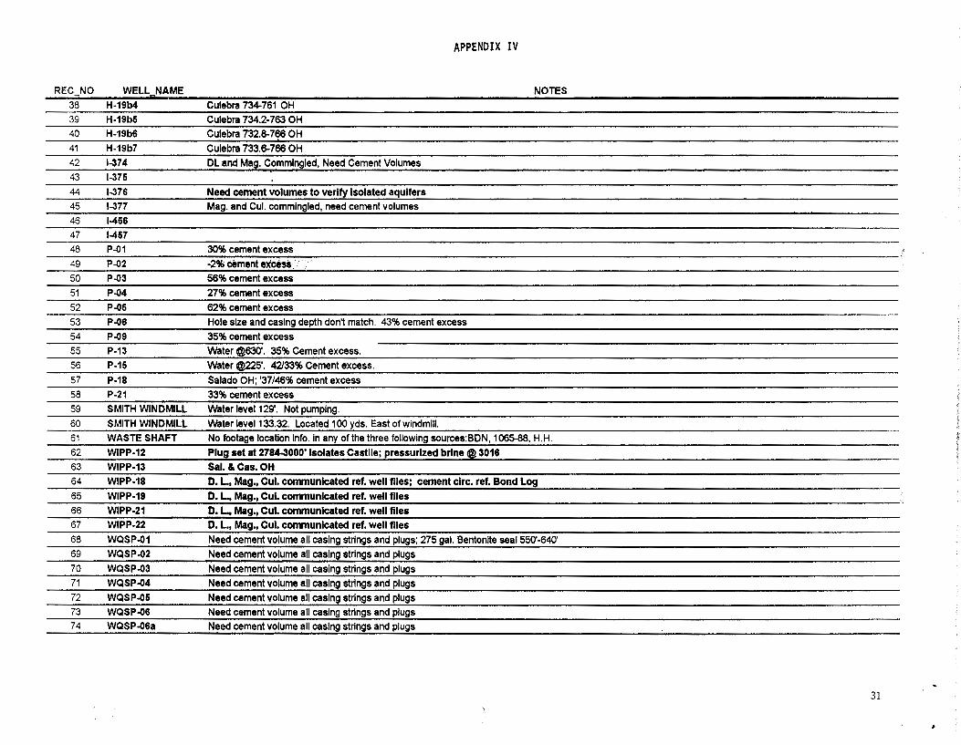
REC_NO WELL_NAME NOTES 38 H-19b4 Culebra 734-761 OH 39 H-19b6 Culebra 734.2-763 OH 40 H-19b6 Culebra 732.8-766 OH 41 H-19b7 Culebra 733.6-766 OH 42 1-374 DL and Mag. Commingled, Need Cement Volumes 43 1-375 44 1-376 Need cement volumes to verify Isolated aquifers 45 1-377 Mag. and Cul. commingled, need cement volumes 46 1-466 47 1-467 48 P-01 30% cement excess 49 P-02 -2% cement excess .. 50 P-03 56% cement excess 51 P-04 27% cement excess 52 P-05 62% cement excess 53 P--06 Hole size and casing depth don't match. 43% cement excess 54 P-09 35% cement excess 55 P-13 Water @630'. 35% Cement excess. 56 P-15 Water @225'. 42133% Cement excess. 57 P-18 Salado OH; '37/46% cement excess 58 P-21 33% cement excess 59 SMITH WINDMILL Water level 129'. Not pumping. 60 SMITH WINDMILL Water level 133.32. Located 100 yds. East of windmill. 61 WASTE SHAFT No footage location Info. In any of the three following sources:BDN, 1065-88, H.H. 62 WIPP-12 Plug set at 2784-3000' Isolates Castile; pressurized brine @ 3016 63 WIPP-13 Sal. & Cas. OH 64 WIPP-18 D. L, Mag., Cul. communicated ref. well flies; cement clrc. ref. Bond Log 65 WIPP-19 D. L, Mag., Cul. communicated ref. well flies 66 WIPP-21 D. L., Mag., Cul. communicated ref. well files 67 WIPP-22 D. L., Mag., Cul. communicated ref. well files 68 WQSP-01 Need cement volume all casing strings and plugs; 275 gal. Bentonlte seal 550'-640' 69 WQSP-02 Need cement volume all casing strings and plugs 70 WQSP-03 Need cement volume all casing strings and plugs 71 WQSP-04 Need cement volume all casing strings and plugs 72 WQSP-06 Need cement volume all casing strings and plugs 73 WQSP-06 Need cement volume all casing strings and plugs 74 WQSP-06a Need cement volume all casing strings and plugs
31
BDB_LOC BDB_ELEV
TD COMP_OATE
CEMENT lALLXQ;..-)J
:::~:.·:4'1.0Dt;SZ';/c --- - --. - --.. --~·· .-.-.: . ... zt"zu ·.:Jfit·_~.za ·
·HOlt/f;_t;iH)EP _·_:_ ,._: __ ..... ,._,_.;.,.(._.=_..'._" -------'----
· ··· .. · :. ~'-!":rD.· ·1·;11. ... , ... ~~i~- .~ ..... , ·.·_ ...•.. ·. > 4ll5e?l5!P · .···.: ; .. 6Al~~e
. .... . . <;E:MZ;~_ ... . - - - --·~· DWY.:_LAKE
MA<3 ClJL SAL
CAST NOTES
APPENDIX IV
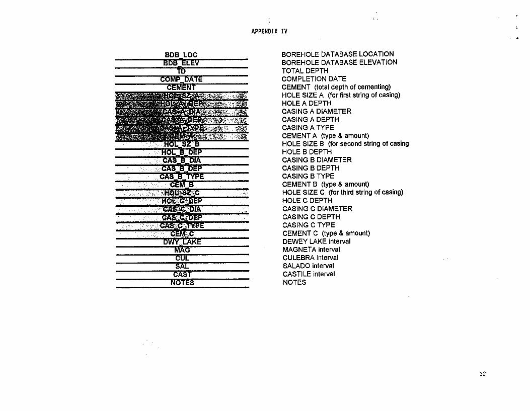
BOREHOLE DATABASE LOCATION BOREHOLE DATABASE ELEVATION TOTAL DEPTH COMPLETION DATE CEMENT (total depth of cementing) HOLE SIZE A (for first string of casing) HOLE A DEPTH CASING A DIAMETER CASING A DEPTH CASING A TYPE CEMENT A (type & amount) HOLE SIZE B (for second string of casing HOLE B DEPTH CASING B DIAMETER CASING B DEPTH CASING B TYPE CEMENT B (type & amount) HOLE SIZE c (for third string of casing) HOLEC DEPTH CASING C DIAMETER CASING C DEPTH CASING C TYPE CEMENT C (type & amount) DEWEY LAKE inteival MAGNETA inteivat CULEBRA inteivat SALADO inteivat CASTILE inteival NOTES
.. .,
32

.. FIGURE 1
34

.. .
- '.
• ~ ...
z
• •
... .....
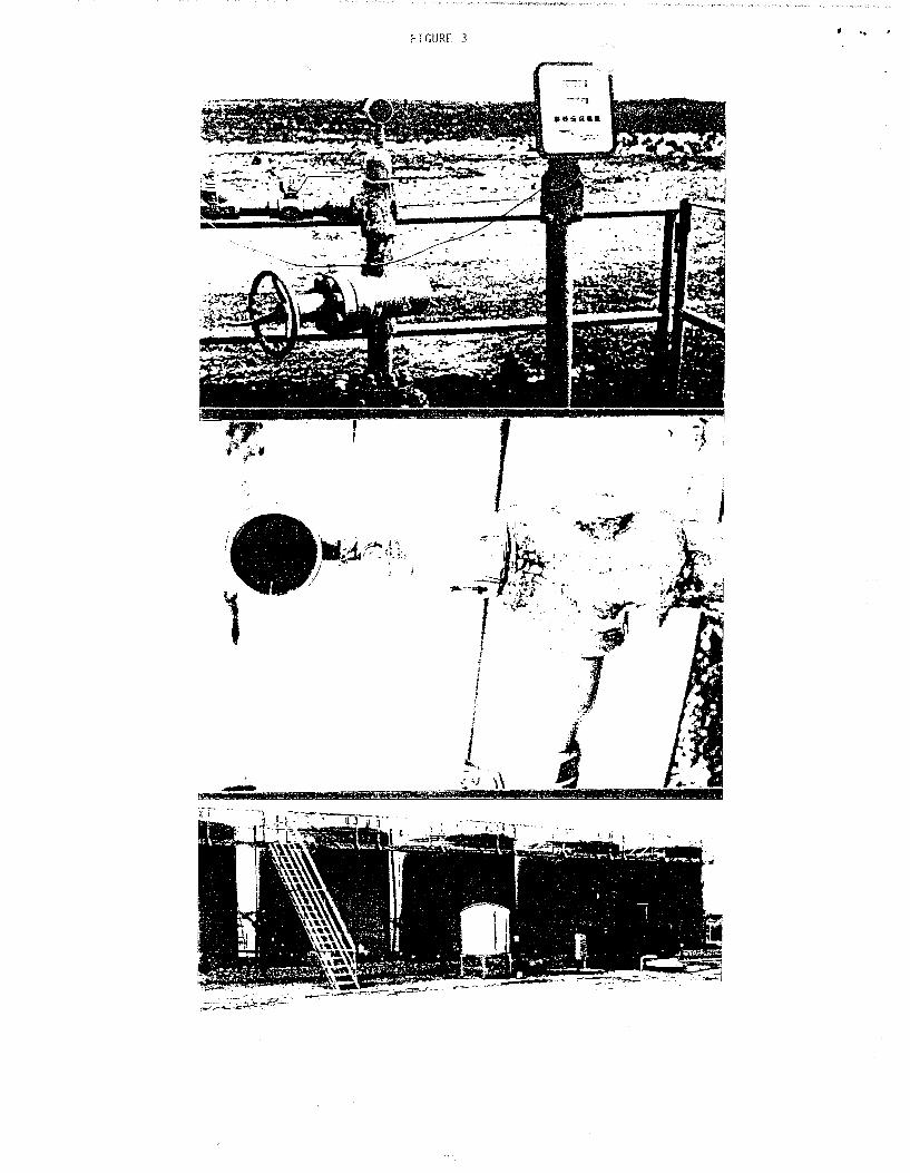
FIGURE 3 ..
":;J~~-~ - ~
'~
J
' NllJ& 11114442

..
NMED/DOE/ AIP-96/3/96Bore.kem
APPENDIXV
Well Name Commingled formations Comments
l Cotton Baby Salado, Castile Plugging does not cover the listed commingled formations
2 D-123 Dewey Lake, Magenta, Salado Cement volume does not cover commingled formations
3 D-207 Dewey Lake, Magenta Plugging does not cover the listed commingled formations
4 ERDA-9 Salado, U. Castile Plugged from 0-2425; repository zone not cemented
5 H-1 Dewey Lake, Magenta, Culebra * Bond Log indicates possible hydraulic connection
6 H-02a Magenta, Culebra OH 513-654'
7 H-03dl Dewey Lake, Magenta, Culebra OH 39-554'
8 H-16 Dewey Lake, Magenta, Culebra, Salado OH 460-851'
9 1-374 Dewey Lake, Magenta AIP suspects more commingled formations but lacks cement
record information
10 1-377 Magenta, Culebra AIP suspects more commingled formations but lacks cement
record information
11 WIPP-13 Salado, Castile OH 1035-3868'
12 WIPP-18 Dewey Lake, Magenta, Culebra * * Cement records indicate OH through commingled formations;
Bond Log on this well indicates cement circulated to surface
13 WIPP-19 Dewey Lake, Magenta, Culebra ** Cement records indicate OH through commingled formations;
SAND87-0039 reports cement circL1lated to surface
14 WIPP-21 Dewey Lake, Magenta, Culebra * * Cement records indicate OH through commingled formations;
SAND87-0039 reports cement circL1lated to surface
15 WIPP-22 Dewey Lake, Magenta, Culebra ** Cement records indicate OH through commingled formations;
SAND87-0039 reports cement circL1lated to surface
* H-1 reported circulating cement to surface in hole history reports. This information conflicts with cement bond log interpretation.
** WIPP 18-22 reported circulating cement to surface in SAND87-0039. This information conflicts wi1h well records and Basic Data
Reports. AIP staff suspects that these wells are compliant but sundry notices are needed to confirm this report.
30