Embed Size (px)
Citation preview
© copyright FACULTY of ENGINEERING ‐ HUNEDOARA, ROMANIA 187
1. Camelia PINCA‐BRETOTEAN, 2. Gladiola CHEȚE
STATIC ANALYSIS OF A ROLLING CHASSIS USING CATIA V5
1. UNIVERSITY POLITEHNICA TIMISOARA, FACULTY OF ENGINEERING HUNEDOARA, ROMANIA ABSTRACT: The paper presents a static stresses and deformation analysis of a rolling chassis, designed and developed to equip the laboratory of "Computation and construction of road vehicles" in the Faculty of Engineering of Hunedoara. The elements of rolling chassis belonged to a car chassis Renault Clio II damaged, steering elements belonging to a Ford Mondeo car and elastic elements are specific of Dacia Logan suspension. These items were placed on a structure made of resistance profiles, conveniently located to obtain a rigid assembly. The rolling chassis is an original conception, unitary approach allows a consistent set of laboratory work together in terms of design and use. Static analysis of structural strength of the rolling chassis was made using Catia V5 design software. The purpose of this analysis is to estimate the limits of resistance of the strenght structure of the rolling chassis for know the possibilities of locating the other units, to extend the experimental function of the chassis. KEYWORDS: deformation analysis, static stresses, Catia V5, rolling chassis INTRODUCTION
Means of education are designed to facilitate the transmission of information, formation of quality, evaluation of new knowledge and last but not least, the development of practical experiments in learning.
These students bring into contact with phenomena, operating principles and building blocks of various assemblies and subassemblies. They can not be explained only by using models, experimental stands and / or by using specific techniques and tools. The role of these models and experimental stands is to provide support for students to learn and deepen the theoretical elements presented in courses.
They also create standardization in understanding and interpreting new knowledge, the disciplines covered. The paper proposes a static analysis of stress and deformation state of resistance structure designed to support assemblies of its composition. The purpose of this analysis is to estimate the limits of resistance of the structure of the rolling chassis for know the possibilities of locating the other units to extend the experimental function of the chassis.
The rolling chassis is an original conception, unitary approach allows a consistent set of laboratory work together in terms of design and use. It allows: � constructive analysis of steering system components;
knowledge of building mechanical steering box pinion and rack; determination of geometrical parameters and the calculation of functional parameters; determination of the steering system games; knowledge of possible steering system failure,
� constructive analysis of brake system components; � constructive analysis of articulated front bridges, made of two semibridge with independent wheel; � constructive analysis of the rigid rear axle; � constructive analysis of the suspension with coil springs and double acting telescopic hydraulic shock
absorber. PRESENTATION OF ANALYSIS DOMAIN
The elements of rolling chassis belonged to a car chassis Renault Clio II damaged, steering elements belonging to a Ford Mondeo car and elastic elements are specific of Dacia Logan suspension.
Renault Clio II car was equipped with a compression ignition engine, with 4‐cylinder in line with a maximum power of 60CP and engine capacity of 1196 cm3 , transverse disposed to the previous bridge.
In table 1 presents the composition of the main parts of the damaged vehicle, and in table 2 the main features of its size and mass.
Table 1. The composition of the main parts of the damaged vehicle Subassembly Renault Clio II car subassembly composition
Front bridge consists of two semibridge Mc Pherson suspension, designed for lower triangles and stabilizer bars, with coil springs and telescopic shock absorbers with hydraulic double acting
Rear axel bridge as a rigid torsion profile in the form of "U" to be welded two arms drawn
Brakes system with ABS electronic distributing; front brakes are ventilated with discs and floating calipers front spidel fixed, and rear brakes are with drums
Steering system electrically assisted steering box pinion and rack, type MATIC ELF Renault D2, Mobil ATF 220
ANNALS OF FACULTY ENGINEERING HUNEDOARA – International Journal Of Engineering
Tome X (Year 2012). Fascicule 3. ISSN 1584 – 2673 188
Table 2. The main features of its size and mass Dimensional characteristics Mass characteristics
Length [mm]
Width [mm]
Height [mm]
Empty car [kg]
Maximum authorized mass [kg]
Total mass [kg]
3803 1940 1356 1095 1415 2519
Because, Renault Clio II vehicle was damaged, we could not use: engine, steering system components and the rear coil springs, other elements being used in the constructive and functional point of view. In order to achieve the rolling chassis assemblies was necessary to remove the damaged car Renault Clio II and purchase other items needed for the chassis.
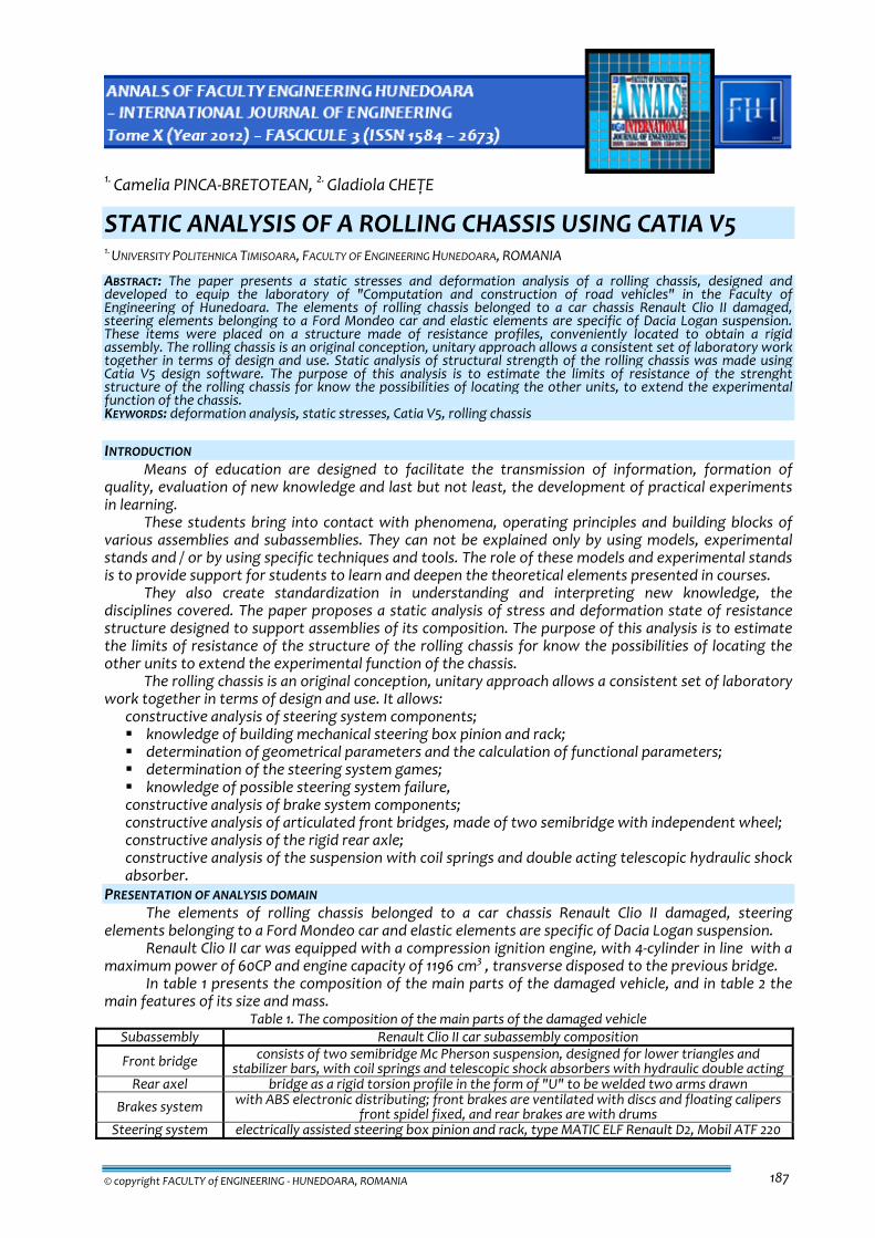
In performing the rolling chassis wanted a building that respects size car Renault Clio II as its technical book. This allowed the design of a strength structure against which resistance was achieved front bridge and rear axle. The strength structure was made in support of the so convenient to be satisfactory and to achieve hardening of all. In making the strength structure were used square profiles 40 x 40 mm and 30 x 30 mm. Elements for stiffening the assembly have been conveniently arranged vertical, horizontal or inclined position, so we obtained a spatial strength structure. In Figure 1 presents details of the strength, during construction works. In order to better positioning of pipes associated braking system, the strength structure of resistance to put a skid plate with thickness of 5 mm. This allowed the driver seat position, but a better stand and fixing specific brake pipes.
Renault Clio II was equipped with Bosch 5.3 anti‐lock wheels, four additional pipe type, unit and associated pipework are used in the assembly of rolling chassis. Because the car that led to the realization of rolling chassis was equipped with power steering and its elements could not be used to achieve the chassis were chose the mechanical variant. In this context, the case of electric assisted directions is the version of the box‐and‐pinion steering with rack chassis. It belonged to the steering system of a Ford Mondeo car. Then were analyzed the schematic diagram of a classic steering gears, and ability to adapt to this scheme as a whole rolling chassis.
a‐ front brige b‐ rear axel c‐ assembly of strength structure
Figure 1. Strength structure of the rolling chassis After analyzing the possibilities of mounting steering system was confirmed the choice of variant
constructive pinion steering box side angle and rack mounted. Mounting box is made with spherical joints axis mounted vertically above the wheel and the horizontal axis of the wheels and levers behind axel pin willing to back.
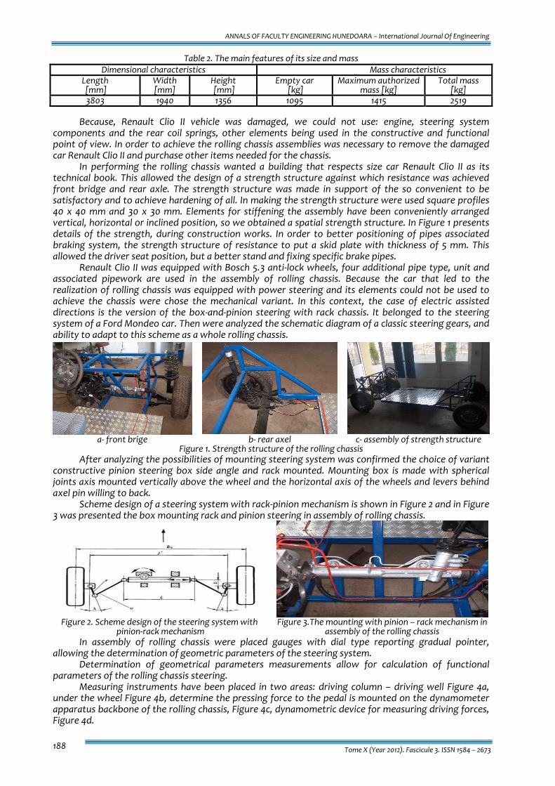
Scheme design of a steering system with rack‐pinion mechanism is shown in Figure 2 and in Figure 3 was presented the box mounting rack and pinion steering in assembly of rolling chassis.
Figure 2. Scheme design of the steering system with
pinion‐rack mechanism Figure 3.The mounting with pinion – rack mechanism in
assembly of the rolling chassis In assembly of rolling chassis were placed gauges with dial type reporting gradual pointer,
allowing the determination of geometric parameters of the steering system. Determination of geometrical parameters measurements allow for calculation of functional
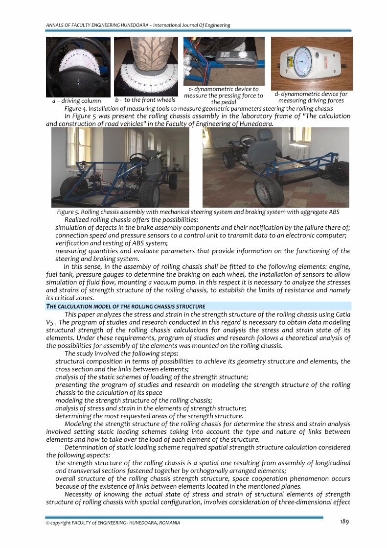
parameters of the rolling chassis steering. Measuring instruments have been placed in two areas: driving column – driving well Figure 4a,
under the wheel Figure 4b, determine the pressing force to the pedal is mounted on the dynamometer apparatus backbone of the rolling chassis, Figure 4c, dynamometric device for measuring driving forces, Figure 4d.
ANNALS OF FACULTY ENGINEERING HUNEDOARA – International Journal Of Engineering
© copyright FACULTY of ENGINEERING ‐ HUNEDOARA, ROMANIA 189
a – driving column
b ‐ to the front wheels
c‐ dynamometric device to
measure the pressing force to the pedal
d‐ dynamometric device for measuring driving forces
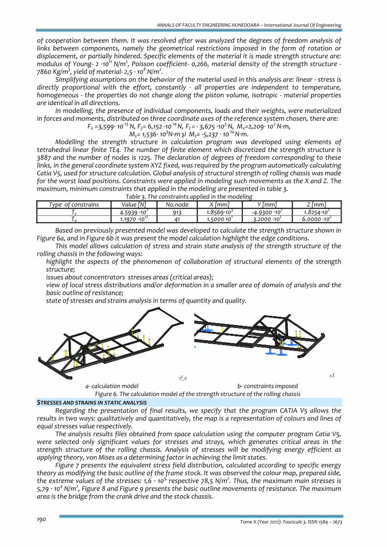
Figure 4. Installation of measuring tools to measure geometric parameters steering the rolling chassis In Figure 5 was present the rolling chassis assambly in the laboratory frame of "The calculation
and construction of road vehicles" in the Faculty of Engineering of Hunedoara.
Figure 5. Rolling chassis assembly with mechanical steering system and braking system with aggregate ABS
Realized rolling chassis offers the possibilities: � simulation of defects in the brake assembly components and their notification by the failure there of; � connection speed and pressure sensors to a control unit to transmit data to an electronic computer; � verification and testing of ABS system; � measuring quantities and evaluate parameters that provide information on the functioning of the
steering and braking system. In this sense, in the assembly of rolling chassis shall be fitted to the following elements: engine,
fuel tank, pressure gauges to determine the braking on each wheel, the installation of sensors to allow simulation of fluid flow, mounting a vacuum pump. In this respect it is necessary to analyze the stresses and strains of strength structure of the rolling chassis, to establish the limits of resistance and namely its critical zones. THE CALCULATION MODEL OF THE ROLLING CHASSIS STRUCTURE
This paper analyzes the stress and strain in the strength structure of the rolling chassis using Catia V5 . The program of studies and research conducted in this regard is necessary to obtain data modeling structural strength of the rolling chassis calculations for analysis the stress and strain state of its elements. Under these requirements, program of studies and research follows a theoretical analysis of the possibilities for assembly of the elements was mounted on the rolling chassis.
The study involved the following steps: � structural composition in terms of possibilities to achieve its geometry structure and elements, the
cross section and the links between elements; � analysis of the static schemes of loading of the strength structure; � presenting the program of studies and research on modeling the strength structure of the rolling
chassis to the calculation of its space � modeling the strength structure of the rolling chassis; � analysis of stress and strain in the elements of strength structure; � determining the most requested areas of the strength structure.
Modeling the strength structure of the rolling chassis for determine the stress and strain analysis involved setting static loading schemes taking into account the type and nature of links between elements and how to take over the load of each element of the structure.
Determination of static loading scheme required spatial strength structure calculation considered the following aspects: � the strength structure of the rolling chassis is a spatial one resulting from assembly of longitudinal
and transversal sections fastened together by orthogonally arranged elements; � overall structure of the rolling chassis strength structure, space cooperation phenomenon occurs
because of the existence of links between elements located in the mentioned planes. Necessity of knowing the actual state of stress and strain of structural elements of strength
structure of rolling chassis with spatial configuration, involves consideration of three‐dimensional effect
ANNALS OF FACULTY ENGINEERING HUNEDOARA – International Journal Of Engineering
Tome X (Year 2012). Fascicule 3. ISSN 1584 – 2673 190
of cooperation between them. It was resolved after was analyzed the degrees of freedom analysis of links between components, namely the geometrical restrictions imposed in the form of rotation or displacement, or partially hindered. Specific elements of the material it is made strength structure are: modulus of Young‐ 2 ∙1011 N/m2, Poisson coefficient‐ 0,266, material density of the strength structure ‐7860 Kg/m3, yield of material‐ 2,5 ∙ 108 N/m2.
Simplifying assumptions on the behavior of the material used in this analysis are: linear ‐ stress is directly proportional with the effort, constantly ‐ all properties are independent to temperature, homogeneous ‐ the properties do not change along the piston volume, isotropic ‐ material properties are identical in all directions.
In modelling, the presence of individual components, loads and their weights, were materialized in forces and moments, distributed on three coordinate axes of the reference system chosen, there are:
Fx =3,599∙ 10‐13 N, Fy= 6,152 ∙10‐14 N, Fz = ‐ 3,675 ∙103 N, Mx=2,209∙ 102 N∙m, My= 1,536∙ 103N∙m şi Mz= ‐5,237 ∙ 10‐14 N∙m.
Modelling the strength structure in calculation program was developed using elements of tetrahedral linear finite TE4. The number of finite element which discretized the strength structure is 3887 and the number of nodes is 1225. The declaration of degrees of freedom corresponding to these links, in the general coordinate system XYZ fixed, was required by the program automatically calculating Catia V5, used for structure calculation. Global analysis of structural strength of rolling chassis was made for the worst load positions. Constraints were applied in modeling such movements as the X and Z. The maximum, minimum constraints that applied in the modeling are presented in table 3.
Table 3. The constraints applied in the modeling Type of constrains Value [N] No.node X [mm] Y [mm] Z [mm]
Tz 4.5939 ∙107 913 1.8569∙103 ‐4.9300 ∙102 1.8254∙102 Tx 1.1970 ∙1012 41 1.5000 101 3.2000 ∙102 6.0000 ∙102
Based on previously presented model was developed to calculate the strength structure shown in Figure 6a, and in Figure 6b it was present the model calculation highlight the edge conditions.
This model allows calculation of stress and strain state analysis of the strength structure of the rolling chassis in the following ways: � highlight the aspects of the phenomenon of collaboration of structural elements of the strength
structure; � issues about concentrators stresses areas (critical areas); � view of local stress distributions and/or deformation in a smaller area of domain of analysis and the
basic outline of resistance; � state of stresses and strains analysis in terms of quantity and quality.
a‐ calculation model b‐ constraints imposed
Figure 6. The calculation model of the strength structure of the rolling chassis STRESSES AND STRAINS IN STATIC ANALYSIS
Regarding the presentation of final results, we specify that the program CATIA V5 allows the results in two ways: qualitatively and quantitatively, the map is a representation of colours and lines of equal stresses value respectively.
The analysis results files obtained from space calculation using the computer program Catia V5, were selected only significant values for stresses and strays, which generates critical areas in the strength structure of the rolling chassis. Analysis of stresses will be modifying energy efficient as applying theory, von Mises as a determining factor in achieving the limit states.
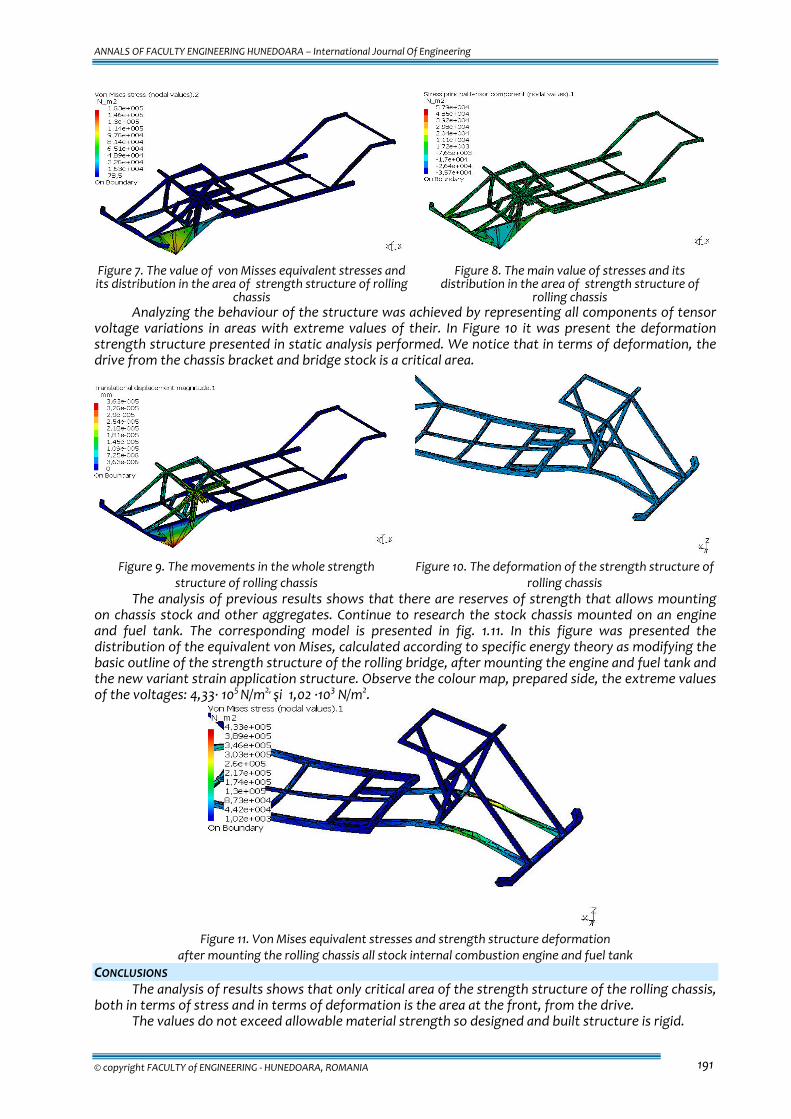
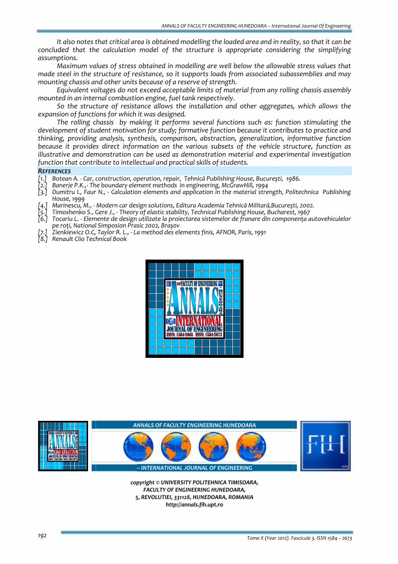
Figure 7 presents the equivalent stress field distribution, calculated according to specific energy theory as modifying the basic outline of the frame stock. It was observed the colour map, prepared side, the extreme values of the stresses: 1,6 ∙ 105, respective 78,5 N/m2. Thus, the maximum main stresses is 5,79 ∙ 104 N/m2, Figure 8 and Figure 9 presents the basic outline movements of resistance. The maximum area is the bridge from the crank drive and the stock chassis.
ANNALS OF FACULTY ENGINEERING HUNEDOARA – International Journal Of Engineering
© copyright FACULTY of ENGINEERING ‐ HUNEDOARA, ROMANIA 191
Figure 7. The value of von Misses equivalent stresses and its distribution in the area of strength structure of rolling
chassis
Figure 8. The main value of stresses and its distribution in the area of strength structure of
rolling chassis Analyzing the behaviour of the structure was achieved by representing all components of tensor
voltage variations in areas with extreme values of their. In Figure 10 it was present the deformation strength structure presented in static analysis performed. We notice that in terms of deformation, the drive from the chassis bracket and bridge stock is a critical area.
Figure 9. The movements in the whole strength
structure of rolling chassis Figure 10. The deformation of the strength structure of
rolling chassis The analysis of previous results shows that there are reserves of strength that allows mounting
on chassis stock and other aggregates. Continue to research the stock chassis mounted on an engine and fuel tank. The corresponding model is presented in fig. 1.11. In this figure was presented the distribution of the equivalent von Mises, calculated according to specific energy theory as modifying the basic outline of the strength structure of the rolling bridge, after mounting the engine and fuel tank and the new variant strain application structure. Observe the colour map, prepared side, the extreme values of the voltages: 4,33∙ 105 N/m2, şi 1,02 ∙103 N/m2.
Figure 11. Von Mises equivalent stresses and strength structure deformation
after mounting the rolling chassis all stock internal combustion engine and fuel tank CONCLUSIONS
The analysis of results shows that only critical area of the strength structure of the rolling chassis, both in terms of stress and in terms of deformation is the area at the front, from the drive.
The values do not exceed allowable material strength so designed and built structure is rigid.
ANNALS OF FACULTY ENGINEERING HUNEDOARA – International Journal Of Engineering
Tome X (Year 2012). Fascicule 3. ISSN 1584 – 2673 192
It also notes that critical area is obtained modelling the loaded area and in reality, so that it can be concluded that the calculation model of the structure is appropriate considering the simplifying assumptions.
Maximum values of stress obtained in modelling are well below the allowable stress values that made steel in the structure of resistance, so it supports loads from associated subassemblies and may mounting chassis and other units because of a reserve of strength.
Equivalent voltages do not exceed acceptable limits of material from any rolling chassis assembly mounted in an internal combustion engine, fuel tank respectively.
So the structure of resistance allows the installation and other aggregates, which allows the expansion of functions for which it was designed.
The rolling chassis by making it performs several functions such as: function stimulating the development of student motivation for study; formative function because it contributes to practice and thinking, providing analysis, synthesis, comparison, abstraction, generalization, informative function because it provides direct information on the various subsets of the vehicle structure, function as illustrative and demonstration can be used as demonstration material and experimental investigation function that contribute to intellectual and practical skills of students. REFERENCES [1.] Botean A. ‐ Car, construction, operation, repair, Tehnică Publishing House, Bucureşti, 1986. [2.] Banerje P.K.,‐ The boundary element methods in engineering, McGrawHill, 1994 [3.] Dumitru I., Faur N., ‐ Calculation elements and application in the material strength, Politechnica Publishing
House, 1999 [4.] Marinescu, M., ‐ Modern car design solutions, Editura Academia Tehnică Militară,Bucureşti, 2002. [5.] Timoshenko S., Gere J., ‐ Theory of elastic stability, Technical Publishing House, Bucharest, 1967 [6.] Tocariu L. ‐ Elemente de design utilizate la proiectarea sistemelor de franare din componența autovehiculelor
pe roți, National Simposion Prasic 2002, Braşov [7.] Zienkiewicz O.C, Taylor R. L., ‐ La method des elements finis, AFNOR, Paris, 1991 [8.] Renault Clio Technical Book
ANNALS OF FACULTY ENGINEERING HUNEDOARA
– INTERNATIONAL JOURNAL OF ENGINEERING
copyright © UNIVERSITY POLITEHNICA TIMISOARA, FACULTY OF ENGINEERING HUNEDOARA,
5, REVOLUTIEI, 331128, HUNEDOARA, ROMANIA http://annals.fih.upt.ro


![Nye Annals[1]](https://img.pdfslide.net/doc/110x75/577d216e1a28ab4e1e9538aa/nye-annals1.jpg)