Embed Size (px)
Citation preview
“STATIC AND DYNAMIC ANALYSIS OF HIGH CONTACT RATIO SPUR
GEAR DRIVE”
A thesis submitted in the partial fulfillment
of the requirements for the degree of
Master of Technology
In
Mechanical Engineering
[Machine Design and Analysis]
Submitted by
Sonawane Ishan R.
(211ME1162)
Under the esteemed guidance of
Prof. S. C. Mohanty
DEPARTMENT OF MECHANICAL ENGINEERING
NATIONAL INSTITUTE OF TECHNOLOGY ROURKELA
YEAR 2012-2013
NATIONAL INSTITUTE OF TECHNOLOGY
ROURKELA
CERTIFICATE
This is to certify that the thesis entitled, “STATIC AND DYNAMIC
ANALYSIS OF HIGH CONTACT RATI0 SPUR GEAR DRIVE” submitted
by Mr. Sonawane Ishan R. in partial fulfillment of the requirements for the award
of Master Of Technology degree in Mechanical Engineering with specialization
in Machine Design and Analysis at the National Institute of Technology,
Rourkela (India) is an authentic work carried out by him under my supervision and
guidance.
To the best of my knowledge, the matter embodied in the thesis has not been
submitted to any other University / Institute for the award of any degree or
diploma.
Date:
Dr. S. C. Mohanty
Assoc. Professor
Department of Mechanical Engineering
National Institute of Technology
Rourkela-769008
ACKNOWLEDGEMENT
First and foremost I offer my sincerest gratitude and respect to my
supervisor and guide Dr. S. C. Mohanty, Department of Mechanical Engineering,
for his invaluable guidance and suggestions to me during my study. I consider
myself extremely fortunate to have had the opportunity of associating myself with
him for one year. This thesis was made possible by his patience and persistence.
After the completion of this Thesis, I experience a feeling of achievement
and satisfaction. Looking into the past I realize how impossible it was for me to
succeed on my own. I wish to express my deep gratitude to all those who extended
their helping hands towards me in various ways during my tenure at NIT Rourkela.
I greatly appreciate & convey my heartfelt thanks to my colleagues, dear ones &
all those who helped me in the completion of this work.
I am especially indebted to my parents for their love, sacrifice, and support.
They are my first teachers after I came to this world and have set great examples
for me about how to live, study and work.
I also express my sincere gratitude to Dr. K. P. Maity, Head of the
Department; Mechanical Engineering for valuable departmental facilities.
Sonawane Ishan R.
Roll No: - 211ME1162
INDEX
CHAPTER NO. TITLE PAGE NO
Abstract і
Motivation of work і і
Objectives of work і і
Nomenclature і і і
1 INTRODUCTION
1.1 History of gearing 1
1.2 Contact ratio 2
1.3 High contact ratio gear 4
2 LITERATURE SURVEY
2.1 Literature study 6
2.2 Present work 16
3 MATHEMATICAL MODELLING
3.1 Equation of motion 17
3.2 Stiffness calculation 22
3.2.1 Tooth stiffness 24
3.2.2 Mesh stiffness 27
3.3 Load sharing in pairs analysis 27
3.4 Dynamic load analysis 28
3.5 Contact stress analysis 28
4 RESULT AND DISSCUSSION
4.1 Mesh stiffness 31
4.2 Normal tooth load 32
CHAPTER NO. TITLE PAGE NO
4 RESULT AND DISSCUSSION
4.3 Dynamic load 33
4.4 Contact stress 36
5 CONCLUSION AND FUTURE SCOPE
5.1 Conclusion 39
5.2 Future scope 40
6 REFERENCES 41
LIST OF FIGURES
FIGURE NO TITLE PAGE NO
1.1 Sketch of early gear system 1
1.2 Contact ratio 3
3.1 Typical gear rotor system 17
3.2 Modelling of a gear mesh 18
3.3 Teeth meshing in high contact ratio 19
3.4 Alteration of number of contact pairs 22
3.5 Tooth of a gear 24
4.1 Stiffness variation with pinion roll angle 31
4.2 Load sharing in pairs analysis 32
4.3 Variation of dynamic load on pinion tooth 33
for 1rpm pinion speed
4.4 Variation of dynamic load on pinion tooth 34
for 2500 rpm pinion speed
4.5 Variation of dynamic load on pinion tooth 34
for 5000 rpm pinion speed
4.6 Variation of dynamic load on pinion tooth 35
for 10000 rpm pinion speed
4.7 Variation of maximum compressive and tensile principal 36
stresses on pinion tooth for 1rpm pinion speed
4.8 Variation of maximum compressive and tensile principal 37
stresses on pinion tooth for 2500 rpm pinion speed
4.9 Variation of maximum compressive and tensile principal 37
stresses on pinion tooth for 5000 rpm pinion speed
4.10 Variation of maximum compressive and tensile principal 38
stresses on pinion tooth for 10000 rpm pinion speed
LIST OF TABLE
TABLE NO TITLE PAGE NO
3.1 Gear data 30
Page | i
ABSTRACT
In this work, an analytical method has been presented for calculating the load sharing
among the meshing teeth in high contact ratio spur gearing. Assumption for this procedure is
that the tooth deflection at each of two or three pairs of contact is equal in all cases and the
sum of normal loads contributed by each of two or three pairs of contact is equal to maximum
normal load.
Dynamic loads on high contact ratio spur gears are calculated by using an analytical
model based on torsional vibration of gears. Dynamic load variations during a mesh cycle of
a tooth are determined. Variable stiffnesses of gear teeth which are required for dynamic load
calculations are found by using analytical expressions. Bending, shear, axial compression and
Hertzian contact deflections are considered for tooth stiffness calculation. Viscous damping
and friction among the mating teeth are also included in this analysis. Contact stresses are
calculated by using analytical expressions developed for two elastic bodies held in contact by
forces normal to the area of contact and accompanied by tangential frictional force. Contact
stress variations during a mesh cycle of a tooth are determined. It is found that the operating
speed has a significant influence on the dynamic load acting on the gear tooth. The magnitude
and location of maximum dynamic load changes with operating speed.
Keywords- High contact ratio, Spur gears, Mesh stiffness, Dynamic load
Page | ii
MOTIVATION OF WORK
The dynamic analysis of the gears has become important part due to the pressing need
of high speed and heavy load carrying machinery. In such applications, due to high precision,
periodic variation of tooth stiffness is the only cause of noise and vibration. A high contact
ratio spur gear pairs reduces the variation of tooth stiffness and thus to reduce vibration and
noise. It also improves structural efficiency, reliability and power to weight ratio. High
contact ratio gearing (HCRG) applies to gear meshes that have at least two pairs of teeth in
contact at all times i.e. contact ratio of 2.0 or more. This helps in sharing of transmitted load.
Unlike the low contact ratio spur gear drive, in high contact ratio spur gear drive the number
of pairs of teeth in contact varies between two to three. In low contact ratio pair, the gear
tooth is designed for critical loading condition, which corresponds to single pair of teeth
contact and the load on gear tooth is maximum transmitted load. Since in a high contact ratio
gear drives the minimum pairs in contact are more than one, the load sharing between the
pairs to be calculated accurately for economical design of gear drive which will be helpful in
design of high contact ratio spur gear drive. A high contact ratio gear pair improves load
carrying capacity and also decreases tooth root contact stresses.
OBJECTIVES
The objectives of present work are stated below
To understand the working of high contact ratio gears.
Finding out the load sharing between gear teeth.
To calculate stiffness variation with pinion roll angle.
Finding out the dynamic load variation with respect to operational speed.
To determine the principal stresses variation with respect to operational speed.
Page | iii
NOMENCLATURE
xg, xp : Coordinates perpendicular to the pressure line at the centres of the
driven and driving gears respectively
yg, yp : Coordinates in the direction of the pressure line at the centres of the
driven and driving gears respectively
Φ1 : Angle between tooth centre line and line joining point c1 with gear
centre O1
θ1, θ2 : Total angular rotations of driving and driven gears, respectively
θp θg : Fluctuating parts of θ1 and θ2, respectively
ωp, ωg : Rotational speeds of driving and driven shafts, respectively
eg, ep : Geometric eccentricities of driven and driving gears, respectively
t : Time
Xgi : Displacement of tooth profile of gear i along the line of action
Xr : Transmission error
b : Half band width of contact
c1, c2 : Points of tangency of the common tangent to gears 1 and 2 respectively
h1 : Half tooth thickness below the load point
Ei : Young’s modulus of elasticity of gear i
Ka , Kb , Ks : Stiffness of tooth in axial compression, bending and shear respectively
Ke : Effective tooth stiffness
Kh : Hertzian contact stiffness of the tooth
Kpi : Stiffness of teeth pair i
L : Face width of tooth
Lp : Distance between c1 and c2 on the line of contact
m : Module of gears
Page | iv
Po : Maximum contact pressure
Rbi : Radius of base circle of gear i
To : Base circle pitch
Zi : Number of teeth on gear i
α0 : Pitch circle pressure angle
θbi : Half of the tooth thickness angle measured on the base circle of gear i
ρi : Profile radius of curvature of gear i at the point of contact
νi : Poisson’s ratio of gear i
μ : Coefficient of friction
ε : Contact ratio
Cgj : Damping coefficient of teeth pair j
Fdj : Dynamic load on the teeth pair j
Fst : Steady transmitted load
Fpj : Elastic force acting on the pair j
Ffj : Friction force acting on the pair j
Gpj : Damping force acting on the gear pair j
Ji : Ji : Polar mass moment of inertia of gear i
Ti : Torque acting on gear i
X2j-2 : Distance of the teeth pair j from c2on the line of contact
X2j-1 : Distance of the teeth pair j from c1 on the line of contact
mi : Mass of the gear i
me : Resultant mass of the gears
σxx, σyy, σzz : Normal stresses
σ1, σ2 : Principal stresses
τzx : Shear stress

Chapter 1
INTRODUCTION
Page 1
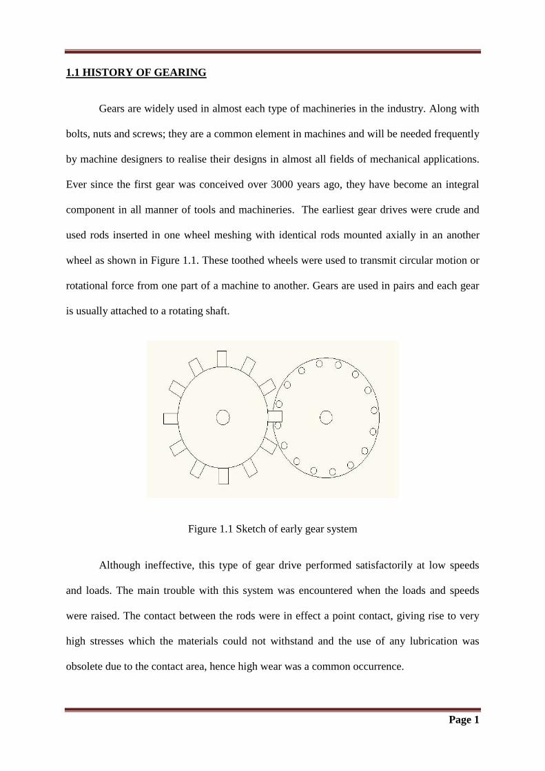
1.1 HISTORY OF GEARING
Gears are widely used in almost each type of machineries in the industry. Along with
bolts, nuts and screws; they are a common element in machines and will be needed frequently
by machine designers to realise their designs in almost all fields of mechanical applications.
Ever since the first gear was conceived over 3000 years ago, they have become an integral
component in all manner of tools and machineries. The earliest gear drives were crude and
used rods inserted in one wheel meshing with identical rods mounted axially in an another
wheel as shown in Figure 1.1. These toothed wheels were used to transmit circular motion or
rotational force from one part of a machine to another. Gears are used in pairs and each gear
is usually attached to a rotating shaft.
Figure 1.1 Sketch of early gear system
Although ineffective, this type of gear drive performed satisfactorily at low speeds
and loads. The main trouble with this system was encountered when the loads and speeds
were raised. The contact between the rods were in effect a point contact, giving rise to very
high stresses which the materials could not withstand and the use of any lubrication was
obsolete due to the contact area, hence high wear was a common occurrence.
Page 2
Although not so obvious at that time, the understanding of the speed ratio of the gear
system was critical. Due to the crude design of the system, the speed ratio was not constant.
As a result, when one gear ran at constant speed, there was regular acceleration and
deceleration of each tooth of the other gear. The loads generated by the acceleration influence
the steady drive loads to cause vibration and ultimately failure of the gear system. Since the
19th century the gear drives designed have mainly been concerned with keeping contact
stresses below material limits and improving the smoothness of the drive by keeping velocity
ratios as constant as possible. The major rewards of keeping the velocity ratio constant is the
reduction of dynamic effects which will give rise to increase in stress, vibration and noise.
Gear design is a highly complicated skill. The constant pressure to build cheaper,
quieter running, lighter and more powerful machinery has given rise to steady and
advantageous changes in gear designs over the past few decades.
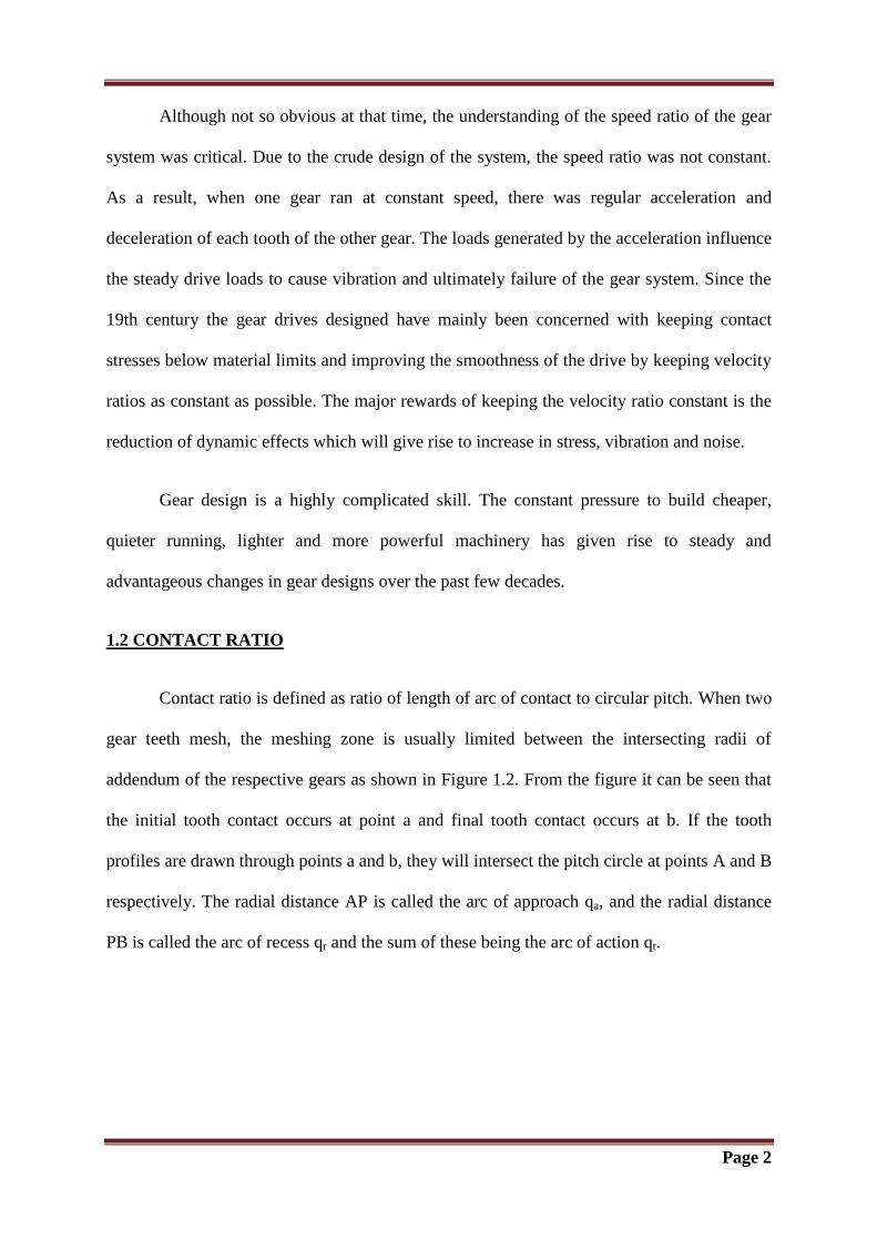
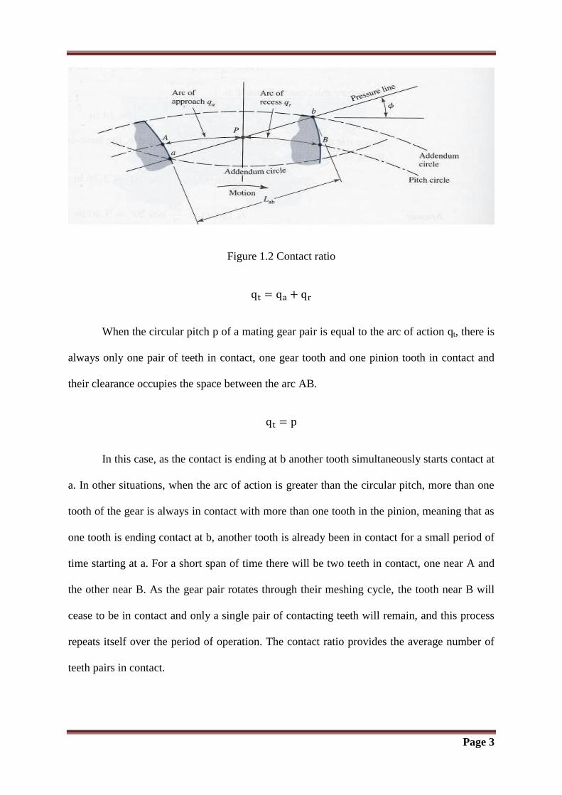
1.2 CONTACT RATIO
Contact ratio is defined as ratio of length of arc of contact to circular pitch. When two
gear teeth mesh, the meshing zone is usually limited between the intersecting radii of
addendum of the respective gears as shown in Figure 1.2. From the figure it can be seen that
the initial tooth contact occurs at point a and final tooth contact occurs at b. If the tooth
profiles are drawn through points a and b, they will intersect the pitch circle at points A and B
respectively. The radial distance AP is called the arc of approach qa, and the radial distance
PB is called the arc of recess qr and the sum of these being the arc of action qt.
Page 3
Figure 1.2 Contact ratio
When the circular pitch p of a mating gear pair is equal to the arc of action qt, there is
always only one pair of teeth in contact, one gear tooth and one pinion tooth in contact and
their clearance occupies the space between the arc AB.
In this case, as the contact is ending at b another tooth simultaneously starts contact at
a. In other situations, when the arc of action is greater than the circular pitch, more than one
tooth of the gear is always in contact with more than one tooth in the pinion, meaning that as
one tooth is ending contact at b, another tooth is already been in contact for a small period of
time starting at a. For a short span of time there will be two teeth in contact, one near A and
the other near B. As the gear pair rotates through their meshing cycle, the tooth near B will
cease to be in contact and only a single pair of contacting teeth will remain, and this process
repeats itself over the period of operation. The contact ratio provides the average number of
teeth pairs in contact.
Page 4
Most gears are generally designed with a contact ratio of more than 1.2, as the contact
ratio is generally reduced due to errors in mounting and assembly of the gear pairs. Gear pairs
operating with low contact ratio are susceptible to interference and damage as a result of
impacts between teeth and thereby leading to an increased level of noise and vibration.
Gears are generally designed with contact ratios of 1.2 to 1.6. A contact ratio of 1.6,
for example, means that 40 per cent of the time one pair of teeth will be in contact and 60 per
cent of the time two pairs of teeth will be in contact. A contact ratio of 1.2 means that 80 per
cent of the time one pair of teeth will be in contact and 20 per cent of the time two pairs of
teeth will be in contact. Gears with contact ratio greater than 2 are referred to as “high-
contact-ratio gears.” For these gears there are never less than two pairs of teeth in contact. A
contact ratio of 2.2 means that 80 per cent of the time two pairs of teeth will be in contact and
20 per cent of the time three pairs of teeth will be in contact. High contact ratio gears are
generally used in selected applications where long life is required. Analysis should be
performed when using high contact ratio gearing because higher bending stresses may occur
in the tooth addendum region. Also higher sliding in the tooth contact can contribute to
distress of the tooth surfaces. In addition higher dynamic loading may occur with high
contact ratio gearing.
1.3 HIGH CONTACT RATIO GEARS
Contact ratio is defined as the average number of pairs of teeth in contact under static
conditions, and with no errors and tooth profile modifications. The term high contact ratio
(HCR) means the gearing that has at least two pairs of teeth in contact at all times i.e. contact
ratio is 2 or more. The percentage change in mesh stiffness for HCR meshes is lower than
low contact ratio (LCR) meshes, so high-quality HCR gear meshes have lower mesh induced
vibration and noise than LCR gear meshes.
Page 5
In advanced gear transmission design, main goals are increased life and reliability and
reduced weight of a gear. High contact ratio gears (HCRG) provides an effective means for
achieving these goals. In HCRG, at least two pairs of teeth in contact at all times, whereas in
standard low contact ratio gears (LCRG), alternate between one and two pairs are in contact.
This enables higher power-to-weight ratio longer life and greater reliability because the
transmitted load is shared between two or more pairs of teeth; the individual tooth load and
stress are less for HCRG than for LCRG designs. HCRG are expected to be dynamically
more sensitive to tooth profile. In gear performance, dynamic loads and stresses are
important. High dynamic loads will increase gear noise and the risk of surface failure, and
large value of dynamic stress at the tooth root can lead to premature tooth fatigue and
fracture. Dynamic analysis is required to determine the load sharing between the two and
three pairs in contact.

Chapter 2
LIETURATURE STUDY
Page 6
2.1 LITERATURE STUDY
Tuplin (1950) [1]
suggested that the number of stress cycles causing failure of a given material
under any particular stress is dependent of the time-rate of repetition of stress. High-speed
gears have failed under stresses lower than the fatigue limit so it becomes necessary to
consider whether the actual stress was as low as had been assumed. Pitch errors and profile
variation in gear teeth cause actual stresses to be higher than nominal stresses. The nominal
permissible stress (corresponding to the mean transmitted torque) should therefore consider
probable errors in the teeth. So spring mass model of mating gears is developed. Equivalent
stiffness was calculated by considering individual stiffnesses. Dynamic loads were
approximated by considering various types of errors.
Houser et al. (1970)[3]
investigated dynamic factors for spur and helical gears.
Comprehensive program was developed for spur and helical to investigate the influence of
errors and variation in mesh stiffnesses on peak stresses. Four sets of specially designed gears
were tested. Tooth loads and system shaft torques at various operating conditions were
compared.
Wilcox et al. (1973) [4]
explained the analytical method of finite elements for analysis of gear
tooth stresses. Necessary details for simulating a two-dimensional tooth shape with finite
elements were outlined and stress values at the tooth surface in the root fillet were
determined. Tensile fillet stress in generated tooth shapes considering either symmetric or
asymmetric profiles was analysed using finite element analysis. Stress data obtained were
used to develop a new simplified stress formula which gives tensile fillet stress as a function
of geometric tooth shape and general loading conditions.
Staph (1976) [5]
developed a computer program to design external spur gears having normal
contact ratios (<2) and high contact ratios (≥ 2). Effects of changes in gear parameters on
Page 7
several performance factors of high contact ratio gears were studied. Then results were
compared with those for the equivalent normal contact ratio gears. It was concluded that a
high contact ratio gear obtained by increasing the addendum of an equivalent normal contact
ratio gear have lower bending and compressive stresses (favourable) and increased friction
heat generation and flash temperatures (unfavourable).
Cornell et al. (1978) [6]
presented a solution for a dynamic model of spur gear systems for all
practical contact ratios. The dynamic response of the gear system and the associated tooth
loads and stressing were determined in this analysis. The dynamic model considered the two
gears as a rigid inertia and the teeth act a variable spring of a dynamic system which was
excited by the meshing action of the teeth. The effects of different parameters like non-
linearity of the tooth pair stiffness in meshing, the tooth errors and the tooth profile
modifications were included in this study. It concluded that system inertia and damping, tooth
profile modification and system critical speeds affect the dynamic gear tooth loads and
stressing dominantly.
J.W.Lund (1978) [7]
described method for calculating the coupled torsional-lateral vibrations
in a geared system of rotors. In this paper both forced vibrations and free
damped vibrations
whose complex Eigen frequencies define the damped critical speeds and the stability of the
rotor system were considered. The Holzer method was used for torsional vibrations and the
Myklestad Prohl method was used for lateral vibrations, after which they were coupled
through impedance matching at the gear meshes.
Elkohly (1985) [9]
gave solution for the calculations of load sharing between teeth in mesh for
high contact ratio gears. In this analysis the sum of tooth deflection, spacing error and profile
modification was assumed to be equal for all pairs in contact. Also the sum of normal loads
taken by pairs was assumed to be equal to the maximum normal load. Stiffness variation
Page 8
along path of contact was considered. Tooth fillet stress, contact stress were determined
using tooth geometry after individual load were calculated. The results obtained from
experimental analysis were compared with analytical results.
Ozguven et al. (1988) [11]
used single degree of freedom non-linear model for the dynamic
analysis of gear pair. Calculations for the dynamic mesh and tooth forces, dynamic factors
based on stresses and dynamic transmission error from measured or calculated loaded static
transmission errors were performed by two methods and a computer program was developed.
The effects of variable mesh stiffness and damping, gear errors pitch, profile errors, run out
errors, profile modifications and backlash were also discussed in this analysis. One of the
methods was accurate and the other one was approximate. In the first method, the time
variation of both mesh stiffness and damping was demonstrated with numerical examples. In
the second method, the time average of the mesh stiffness was used. However, the excitation
effect of the variable mesh stiffness was included in the formulation used in approximate
analysis. It was concluded from the comparison of the results of the two methods that the
displacement excitation resulting from variable mesh stiffness was more important than the
change in system natural frequency resulting from the mesh stiffness variation.
Kahraman et al. (1991) [12]
included coupling between the transverse and torsional motions at
the gear in appropriate dynamic model of a spur gear pair. Though various numerical models
with large degrees of freedom based on the transfer matrix method or the finite element
method were available, reduced order analytical models were preferred for design
calculations or for non-linear analysis. In this study they proposed such model and
determined the associated error in the undamped Eigen solution by a comparison with a finite
element model.
Page 9
Kahraman et al. (1992) [13]
developed a finite-element model for investigation of dynamic
behaviour of geared rotor. Transverse vibration of bearing and transverse and torsional
vibration of shaft were taken into account for this analysis. In this model the rotary inertia of
shaft , the axial loading on shafts, bearing flexibility and damping, material damping of shafts
and the stiffness and the damping of gear mesh were included. The coupling between the
torsional and transverse vibrations of gears was considered in the model. Mesh stiffness was
assumed to be constant. The dynamic mesh forces due to these excitations were calculated.
Ramamurti et al. (1998) [15]
presented the findings of three-dimensional stress analysis of spur
and bevel gear teeth by Finite element method using cyclic symmetry concept. The
displacement of a tooth was computed for each Fourier harmonic component of the contact
line load and all the components were added to obtain the total displacement. This
displacement was used in the calculation of static stress in the teeth. The sub matrices
elimination scheme was used for calculation of natural frequencies and mode shapes. This
analysis demonstrated the use of cyclic symmetry concept in the Finite Element Analysis of
spur gear. This approach helps in large saving in computer memory and reduction of
computational effort. The dynamic analysis of gear tooth was efficiently done by this
approach utilising the geometrical periodicity and the sub matrices elimination scheme.
Parker et al. (2000) [16]
investigated dynamic response of a spur gear pair using a Finite
element/contact mechanics model which suits well for dynamic gear analyses. The gear pair
was tested across a wide range of operating speeds and torques. Comparisons were made with
other researcher’s published experiments that reveal complex non-linear phenomena. The
non-linearity in meshing was due to the contact loss of the meshing teeth. It occurs even for
large torques for high-precision gears also. Dynamic mesh forces were calculated using a
detailed contact analysis at each time step as the gears roll through the mesh. Mesh forces are
Page 10
determined by contact analysis in combination with a unique semi-analytical Finite element
formulation at the tooth mesh.
Huang et al. (2000) [17]
considered a spur gear tooth as a variable cross-section Timoshenko
beam to develop a dynamic model to obtain transient response for spur gears of involute
profiles. A dynamic stiffness method using equations of motion of a Timoshenko beam
model was developed to simulate spur gear dynamics during meshing. In this study the
dynamic responses of a single tooth and a gear pair were investigated. Firstly, Gear blank and
tooth profile were represented as polynomials. The dynamic stiffness matrix and natural
frequencies of the gear were calculated. The modal analysis was used to calculate the forced
response of a tooth subject to a shaft-driven transmission. The forced response was obtained
at arbitrary points in a gear tooth. They considered time varying stiffness and mass matrices
and the gear meshing forces at moving meshing points during the study.
Kapelevich (2000) [18]
developed the basic geometry theory for asymmetric gear teeth.
Method of design of spur gears with asymmetric teeth was described so as to increase load
carrying capacity, minimize weight, overall dimension and vibration levels. It was concluded
that load carrying capacity increases and weight, size decreases with increase in contact ratio
and pressure angle for drive sides. Also the formulas and equations for gear and generating
rack parameters were determined in this study.
Choi et al. (2001) [19]
presented an analytical study of the dynamic characteristics of a geared
rotor-bearing system by the transfer matrix method. Rotating shafts of the system were
modeled as Timoshenko beams with effects of shear deformation and gyroscopic moment.
The gear mesh was modeled as a pair of rigid disks connected by a spring-damper set along
the pressure line and the transmission error was simulated by a displacement excitation at the
mesh. The transfer matrix of a gear mesh was developed. The coupled lateral-torsional
Page 11
vibration of a geared rotor-bearing system was studied. Natural frequencies and
corresponding mode shapes, and whirl frequencies under different spin speeds were
determined. In addition, steady-state responses due to the excitation of mass unbalance,
transmission error and geometric eccentricity gear mesh are obtained. Effect of the time-
varying stiffness of the gear mesh was investigated.
Fong et al. (2002) [20]
proposed a mathematical model for parametric tooth profile of spur
gear by using a given equation of line of action. The line of action was considered to be
usually composed of only simple curves. By combining simple curves into the line of action
the proposed mathematical model enhanced the freedom of tooth profile design. The equation
of line of action was used to derive curvature, sliding velocity, contact ratio, and the
limitation of undercutting. Based on the proposed mathematical model, both mating tooth
profiles by the single parameter of line of action were presented. In this work the kinematical
characteristics of mating gears with nonstandard tooth profiles were studied.
Vedmar et al. (2003) [21]
described method to calculate dynamic gear tooth force and bearing
forces. The model developed in this study also includes elastic bearings. Path of contact and
gear mesh stiffness were determined using the deformations of the gears and the bearings.
This analysis gave contact outside the plane of action and a time varying working pressure
angle. The influence of the friction force was also studied. Dynamic influence on the gear
contact force or on the bearing force in the gear mesh line-of-action direction was not
considered due to friction. On the other hand, the changing of sliding directions in the pitch
point was a source for critical oscillations of the bearings in the gear tooth frictional direction.
These oscillations in the frictional direction appear unaffected by the dynamic response along
the gear mesh line of action direction.
Page 12
Maliha et al. (2004) [22]
described a nonlinear dynamic model for a gear shaft disk bearing
system. This model of a spur gear pair was coupled with linear finite element models of
shafts on which gears are mounted. The nonlinear elasticity term due to backlash was
expressed by a describing function. The excitations considered in the model were external
static torque and internal excitation caused by mesh stiffness variation, gear errors and gear
tooth profile modifications. This work combines the versatility of modeling a shaft-bearing
disk system that can have any configuration without a limitation to the total degree of
freedom, with the accuracy of a nonlinear gear mesh interface model that allowed predicting
jumps and double solutions in frequency response
Wang et al. (2005) [23]
outlined methods for using FEA of high contact ratio spur gears in
mesh, considering adaptive meshing and element size selection under the solution accuracy
criteria. These methods were proficient in a range of loads over the mesh cycle, with and
without modification in tooth profile. This study demonstrated the high contact ratio gears to
provide significant advantages for decreasing tooth root and contact stresses and also
increased load carrying capacity. Earlier numerical work using FEA was limited due to
several factors; (i) the difficulty in predicting load sharing over roll angles covering two or
three teeth simultaneously in mesh (ii) the problem of primary unconstrained body motion
when (long) profile modifications were applied. Methods and results for overcoming these
difficulties with recent computer hardware and software improvements were presented in this
study. Particular developments discussed include the use of FE analysis of High Contact
Ratio Gears in mesh and the results obtained when adaptive meshing was used.
Shuting Li (2007) [24]
presented three-dimensional (3-D), finite element methods (FEM) to
conduct surface contact stress (SCS) and root bending stress (RBS) calculations of a pair of
spur gears with machining errors (ME), assembly errors (AE) and tooth modifications (TM).
In this paper, firstly positions of a pair of parallel-shaft spur gears with ME, AE and TM were
Page 13
defined in a 3-D coordinate system. The tooth contact of the gear pair was assumed on a
reference face around the geometrical contact line. Deformation influence coefficients of the
pairs of contact points were calculated by 3-D, FEM and loaded tooth contact analysis
(LTCA) of the pair of gears with ME, AE and TM was conducted by mathematical
programming method. Tooth contact pattern and root stains of a spur gear pair with assembly
errors were calculated using the programs and these results were compared with experimental
results. Calculated results were in agreement with the measured ones well. It is concluded
that surface contact stress and root bending stress were greater than the case without errors
and tooth modifications.
Podzharov et al. (2008) [25]
used high contact ratio spur gears to exclude or reduce the
variation of tooth stiffness. In this work the analysis of static and dynamic transmission error
of spur gears with standard tooth of 20° profile angle was presented. A simple method for
designing spur gears having a contact ratio nearly 2.0 was used. It included the increasing the
number of teeth on mating gears and simultaneously introducing negative profile shift in
order to provide the same center distance. A tooth mesh of periodic structure was used to
consider deflection and errors of each pair of teeth in the engagement. Computer programs
were developed to calculate static and dynamic transmission error of gears under load. This
analysis of gears concluded that gears with high contact ratio have much less static and
dynamic transmission error than standard gears.
Shuting Li (2008) [26]
investigated the effect of addendum on tooth contact strength, bending
strength and other performance parameters of spur gears. Mathematical programming method
(MPM) and finite element method (FEM) were used together to conduct loaded tooth contact
analyses (LTCA), deformation and stress calculations of spur gears with different addendums
and contact ratios. Tooth load, load-sharing, contact stresses, root bending stresses,
transmission errors and mesh stiffnesses of the spur gears were analyzed. Effects of
Page 14
addendum and contact ratio on gear strength and basic performance parameters were also
discussed.Finally, strength calculations of HCRG by considering misalignment error and lead
crowning were presented in this paper.
Karpat et al. (2008) [27]
presented paper in which the primary objective was to use dynamic
analysis to compare conventional spur gears with symmetric teeth and spur gears with
asymmetric teeth. The secondary objective was to optimize the asymmetric tooth design in
order to minimize dynamic loads. This study described preliminary results to designers for
understanding dynamic behaviour of spur gears with asymmetric teeth. A dynamic model
was developed during study, using MATLAB, and used for the prediction of the
instantaneous dynamic loads of spur gears with symmetric and asymmetric teeth. For
asymmetric teeth, the dynamic factor decreases with increase in addendum. Also the static
transmission error decreases with increasing pressure angle. It is concluded that the
amplitudes of harmonics of the static transmission errors were reduced for asymmetric teeth
with long addendum high gear contact ratio gears.
Kim et al. (2010) [28]
analysed the dynamic response of a pair of spur gears having
translational motion due to bearing deformation. A new dynamic model for the gear set was
formed considering translational motion which means the distance between the centres of a
pinion and a gear varies with time. So the pressure angle and the contact ratio were
considered as time varying variables. The dynamic responses were computed by applying the
Newmark time integration method after deriving nonlinear equations of motion for gears. The
new model gave more accurate dynamic responses. The effects of damping and stiffness upon
the dynamic responses were also investigated.
Ristivojevic et al. (2013) [29]
studied the impact of load distribution in meshed teeth. Also
teeth geometry and manufacturing accuracy on wear of the spur gear tooth flanks were
Page 15
studied in this paper. Due to wearing causes uneven load distribution hence dynamic forces
increases, and thus energy efficiency was decreases. A larger number of impacts on the tooth
flanks stress state were taken into account so as to reach more accurate model for the analysis
of tooth flanks load carrying capacity. A mathematical model depending on the value and
sign of base pitch difference of meshed teeth developed for the contact stress during contact
period. It was concluded that the original geometry and proper teeth mesh were impaired by
adhesive wear. This results in the lower efficiency, larger variation of load distribution and
higher dynamic forces. Uniformity and intensity of tooth flanks wear depend on pitch point
position on the profiles of meshed teeth.
Rincon et al. (2013) [30]
presented the procedure to determine loaded transmission error of a
spur gear transmission as well as meshing stiffness and load sharing ratio. The procedure also
allows a better representation of load transfer between teeth pairs. The analysis of contact
forces and deformations in spur gear transmissions was done using an advanced model. The
deformation at each gear contact point was assumed as a combination of a global and a local
term. The global term was obtained by means of a finite element model and the local term
was described by an analytical approach derived from Hertzian contact theory. The quasi
static behaviour of a single stage spur gear transmission was discussed in this study using
numerical example, which showed the capabilities of the methodology to obtain the loaded
transmission error under several load levels as well as some other related measures such as
load ratio or meshing stiffness.
Page 16
2.2 PRESENT WORK
The dynamic analysis of the gears has become important part due to the pressing need
of high speed and heavy load carrying machinery. A high contact ratio spur gear pair reduces
the variation of tooth stiffness and thus to reduce vibration and noise. It also improves
structural efficiency, reliability and power to weight ratio. With increased requirements of
high speed, heavy load and light weight in gear design, the dynamic load is required to
determine among two or three pairs in contact. In this work, an analytical method is discussed
for calculation of the load sharing among meshing teeth pairs. Also variations of dynamic
load during mesh cycle are determined. Variable stiffnesses which are required for dynamic
load calculations are found using analytical expressions.
This information may be useful in further analysis of High Contact Ratio Spur Gear
drives.

Chapter 3
MATHEMATICAL MODELLING
Page 17
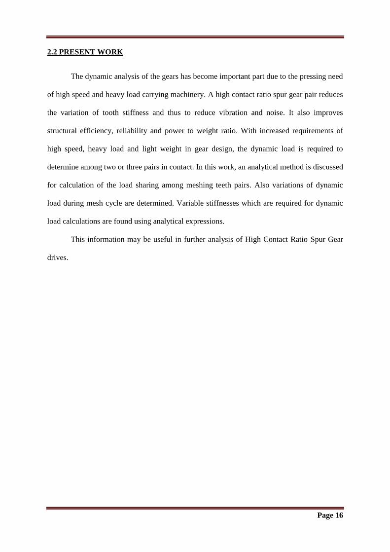
3.1 EQUATION OF MOTION
A typical geared rotor system is shown in Figure 3.1. It consists of a motor connected
to one of the shafts by a coupling, a load at the other end of the other shaft and a gear pair
which couples the shafts. Both shafts are supported at several locations by bearings. Hence
system consists of following elements.
1) Shafts
2) Rigid disks
3) Flexible bearings
4) Gears
Figure 3.1 Typical gear rotor system
When two shafts are not coupled, each gear can be modelled as a rigid disk. However when
they are in mesh, these rigid disks are connected by a spring damper element representing the
mesh stiffness and damping.
Page 18
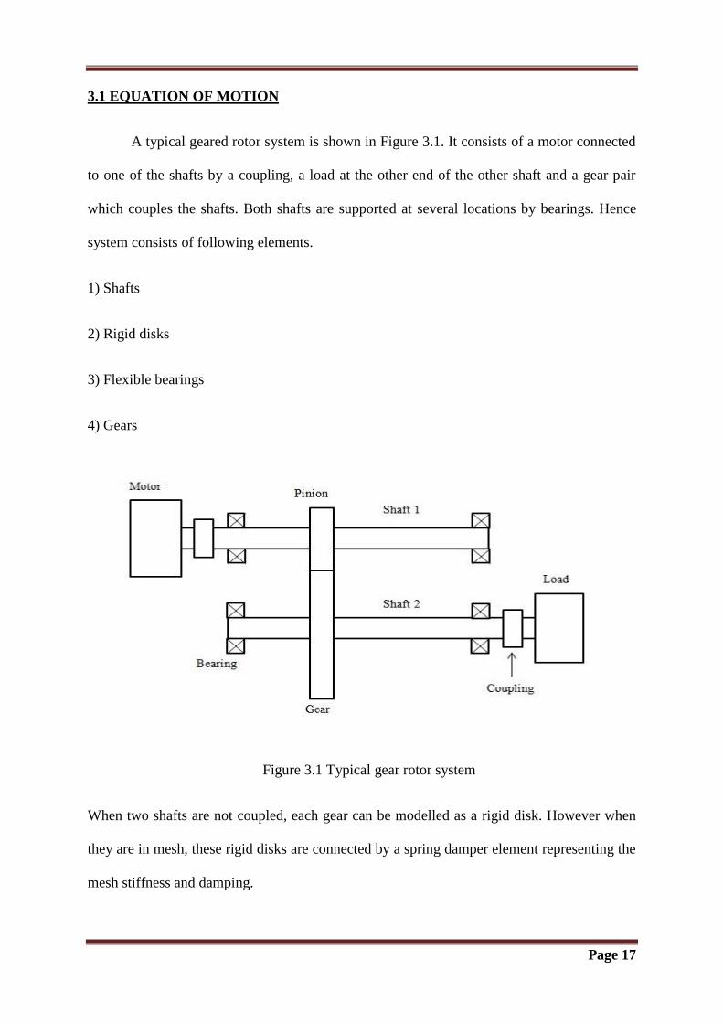
A typical gear mesh represented by a pair of rigid disks connected by a spring and a damper
along the pressure line which is tangent to the base circles of the gears in Figure 3.2.
Figure 3.2 Modelling of a gear mesh
Xgi is displacement of tooth profile of gear i along the line of action.
(1)
(2)
ep and eg are geometric eccentricities of driving and driven gears. and are base circle
radii of the driving and driven gears. The angles θ1 and θ2 are the total angular rotations of the
driving and driven gears, respectively, and are equal to
(3)
(4)
Page 19
Where θp and θg are the alternating parts of rotations and ωp and ωg are the spin speeds of the
driving and driven shafts, respectively. The displacement Xr is considered as the transmission
error at mesh point.
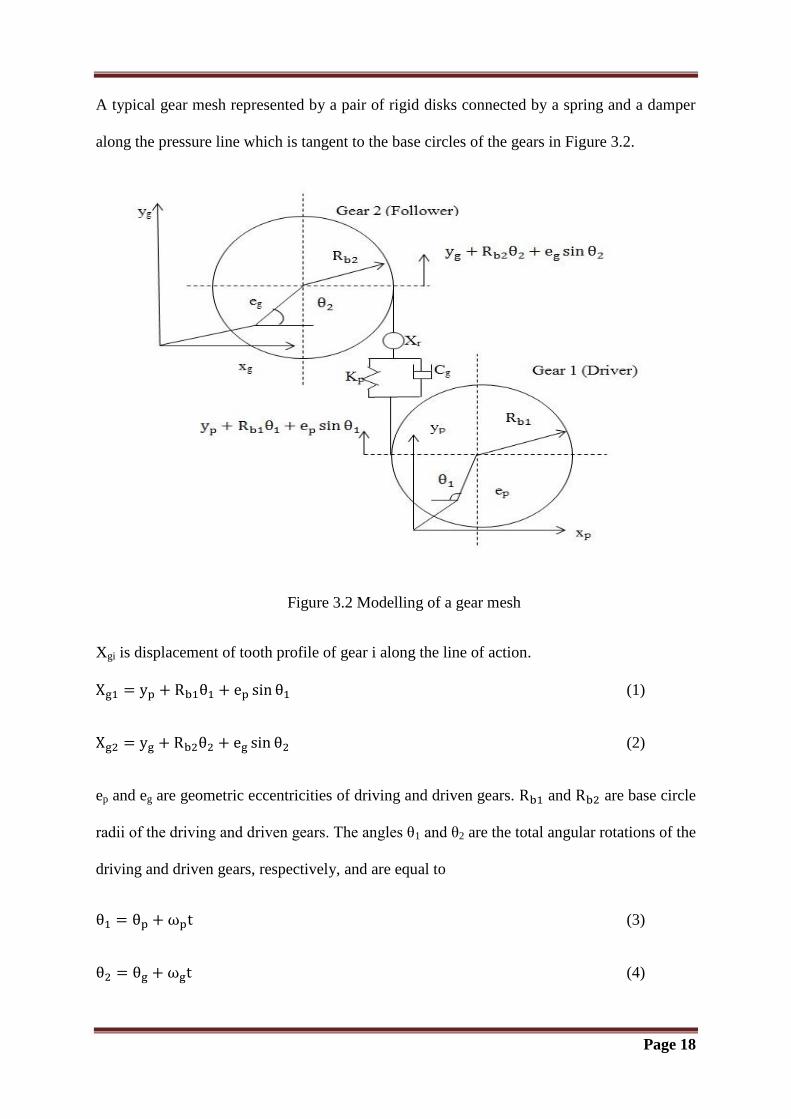
Figure 3.3 Teeth meshing in high contact ratio gears
Page 20
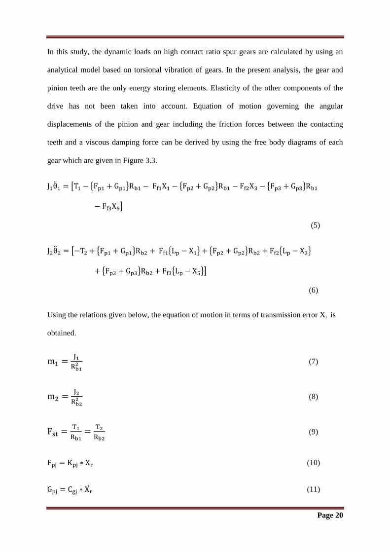
In this study, the dynamic loads on high contact ratio spur gears are calculated by using an
analytical model based on torsional vibration of gears. In the present analysis, the gear and
pinion teeth are the only energy storing elements. Elasticity of the other components of the
drive has not been taken into account. Equation of motion governing the angular
displacements of the pinion and gear including the friction forces between the contacting
teeth and a viscous damping force can be derived by using the free body diagrams of each
gear which are given in Figure 3.3.
[ { } { } { }
]
(5)
[ { } { } { } { }
{ } { }]
(6)
Using the relations given below, the equation of motion in terms of transmission error Xr is
obtained.
(7)
(8)
(9)
(10)
(11)
Page 21
(12)
The equation of motion in terms of Xr is given below
[ ( ) ( ) ( )]
[ ( ) ( ) ( )]
(
)
(13)
(14)
(15)
(16)
√ (17)
(18)
(19)
( )
(20)
Where j=1, 2 and 3
In the above relations, if the speed of the driver is greater than the speed of follower, the sign
is positive otherwise negative.
Page 22
The coefficient of friction between the contacting teeth is calculated by using the semi
empirical formula
√ (21)
Where Vs is the sliding speed measured in m/sec
The damping ratio has a value in the range of 0.03 to 0.17.
In this study, it is taken as 0.1.
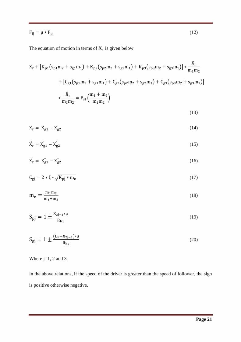
3.2 STIFFNESS CALCULATION
The locations and sizes of the two and three pairs of teeth contact zones can be determined
from the contact ratio and base pitch of the gear pair. These zones are shown in Figure 3.4.
Figure 3.4 Alteration of number of contact pairs
A2-A3, A4-A5, A6-A7 – Three pairs of teeth contact zones
A3-A4, A5-A6 – Two pairs of teeth contact zones
Different contact lengths are shown in above figure.
Page 23
After determining the positions and widths of these contact zones, the corresponding pinion
or gear roll angles are determined from the gear geometry, since each point on the common
normal line can be mapped to a corresponding point on the base circle, using the involute
properties of the spur gear tooth.
Referring to the Figure 3.3, is the angle between the line joining gear centres O1, O2 and
the line O1P1, where P1 is the corresponding point of contact P is mapped on the base circle.
The angles for the reference points A2, A3, A4, A5, A6 and A7 representing the locations of
two and three pairs of teeth contact zones on the common normal line and they are
represented as under.
(22)
(23)
(24)
(25)
(26)
(27)
√
(28)
The angular displacement of gear 1 measured from the gear centre line O1O2 to the
symmetric line the gear tooth is
(29)
(30)
Page 24
The angle can be related to which is again represented as
(31)
Where is the angle between the symmetrical line of tooth and line O1 C1. This is also the
inclination angle of load line with the normal to the symmetrical line of the tooth.
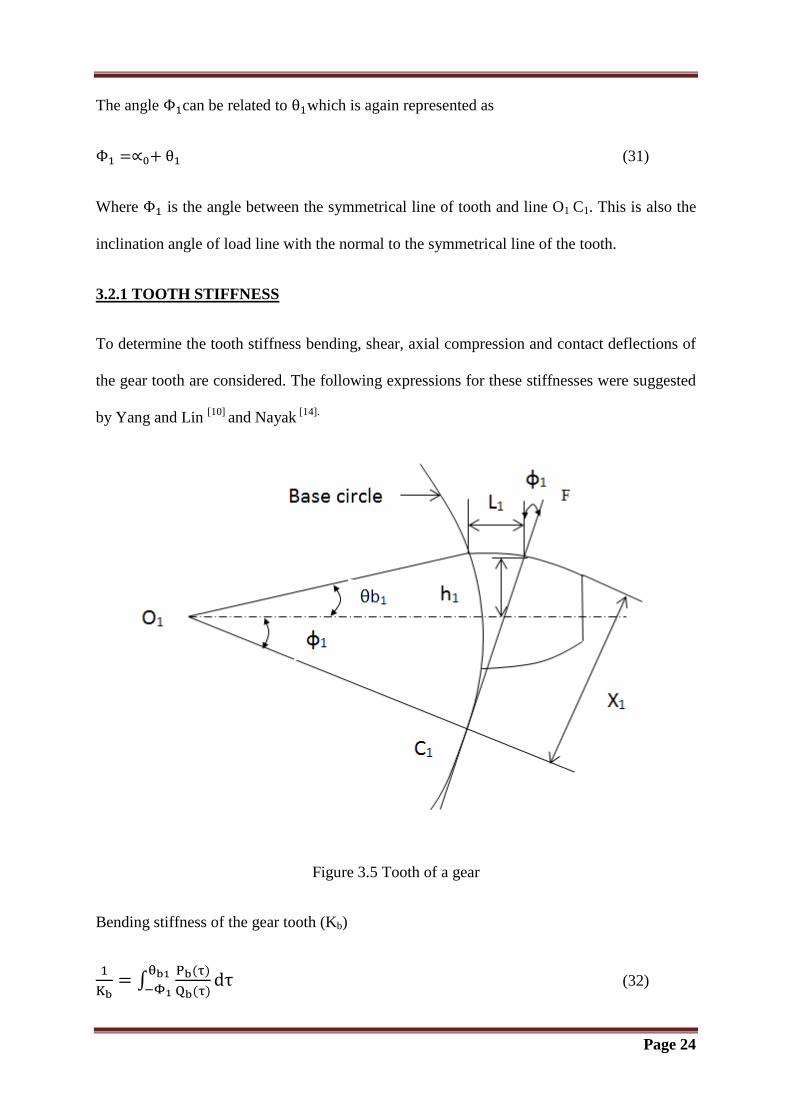
3.2.1 TOOTH STIFFNESS
To determine the tooth stiffness bending, shear, axial compression and contact deflections of
the gear tooth are considered. The following expressions for these stiffnesses were suggested
by Yang and Lin [10]
and Nayak [14].
Figure 3.5 Tooth of a gear
Bending stiffness of the gear tooth (Kb)
∫
(32)
Page 25
Where
, *
+
-
[
] (33)
[ ] (34)
Axial compression stiffness (Ka)
∫
(35)
Where
(36)
[ ] (37)
Shear stiffness of the tooth (Ks)
∫
(38)
Where
[ ] [ { }
{
}
{
}
]
(39)
[ ] (40)
Page 26
Hertzian contact stiffness (Kh)
(41)
Effective tooth stiffness (Ke)
(42)
To find stiffness of the corresponding tooth of the gear 2, the subscripts in the above
equations are to be changed from 1 to 2. is redefined as
(43)
(44)
(45)
(46)
Similarly, for the second pair of teeth X1,X2, and are to be replaced by X3,X4, and
and for the third pair by X5,X6, and respectively, where
(47)
(48)
(49)
(50)
(51)
Page 27
(52)
(53)
(54)
3.2.2 MESH STIFFNESS
The derivation of expression for the mesh stiffness is based on the fact that each meshing pair
is modelled as two springs joined in series and thus subjected to same load.
If the stiffnesses of teeth A, B, C, D, E and F are denoted by KA, KB, KC, KD, KE and KF
respectively, then the combined stiffness of each meshing pair is
(55)
(56)
(57)
3.3 LOAD SHARING IN PAIRS
To calculate the individual tooth load, the profile modification and tooth error are not
considered. When three pairs of teeth are in contact, then
(58)
(59)
Page 28
(60)
When two pairs are in contact, for example, teeth A and B on the driving teeth remain in
contact with teeth D and E on the driven, then
and
(61)
(62)
(63)
3.4 DYNAMIC LOAD
The dynamic load Fdj on the teeth pair is given by following equation
( ) (64)
3.5 CONTACT STRESS ANALYSIS
Contact stresses in contact region can be calculated by using following equations. X axis is
considered along the contact width, y axis along contact length and Z axis is perpendicular to
the contact surface. Origin of axes is at mid-point of contact area.
[ ] (65)
, (
) [ ]
(
) - (66)
(67)
Page 29
, * (
) + (
) - (68)
Where
(69)
(70)
[ ] (71)
[ ] (72)
(
)
(73)
(
)
(74)
(
) (75)
(76)
Following equations are used to calculate the stresses on the surface
[
(
)
] , (77)
[
(
)
] , (78)
[
(
)
] , (79)
Page 30
[(
)
], (80)
, , (81)
[(
)
], , (82)
The principal stresses in the X-Z plane can be calculated by using the equations for principal
strain for plain strain condition
[(
)
]
(83)
(84)
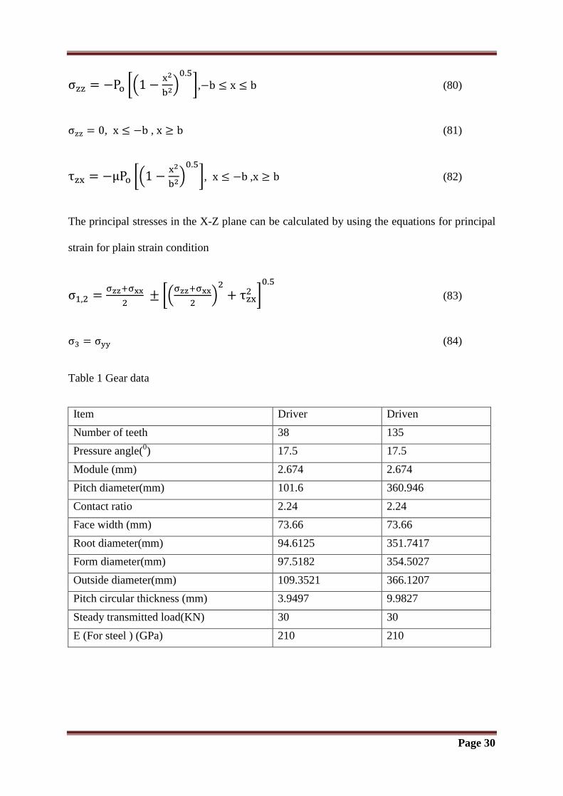
Table 1 Gear data
Item Driver Driven
Number of teeth 38 135
Pressure angle(0) 17.5 17.5
Module (mm) 2.674 2.674
Pitch diameter(mm) 101.6 360.946
Contact ratio 2.24 2.24
Face width (mm) 73.66 73.66
Root diameter(mm) 94.6125 351.7417
Form diameter(mm) 97.5182 354.5027
Outside diameter(mm) 109.3521 366.1207
Pitch circular thickness (mm) 3.9497 9.9827
Steady transmitted load(KN) 30 30
E (For steel ) (GPa) 210 210

Chapter 4
RESULT AND DISSCUSSION
Page 31
4.1 MESH STIFFNESS
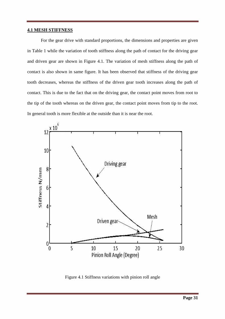
For the gear drive with standard proportions, the dimensions and properties are given
in Table 1 while the variation of tooth stiffness along the path of contact for the driving gear
and driven gear are shown in Figure 4.1. The variation of mesh stiffness along the path of
contact is also shown in same figure. It has been observed that stiffness of the driving gear
tooth decreases, whereas the stiffness of the driven gear tooth increases along the path of
contact. This is due to the fact that on the driving gear, the contact point moves from root to
the tip of the tooth whereas on the driven gear, the contact point moves from tip to the root.
In general tooth is more flexible at the outside than it is near the root.
Figure 4.1 Stiffness variations with pinion roll angle
Page 32
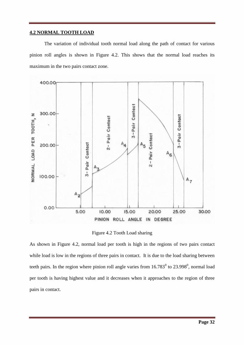
4.2 NORMAL TOOTH LOAD
The variation of individual tooth normal load along the path of contact for various
pinion roll angles is shown in Figure 4.2. This shows that the normal load reaches its
maximum in the two pairs contact zone.
Figure 4.2 Tooth Load sharing
As shown in Figure 4.2, normal load per tooth is high in the regions of two pairs contact
while load is low in the regions of three pairs in contact. It is due to the load sharing between
teeth pairs. In the region where pinion roll angle varies from 16.7830 to 23.998
0, normal load
per tooth is having highest value and it decreases when it approaches to the region of three
pairs in contact.
Page 33
4.3 DYNAMIC LOAD
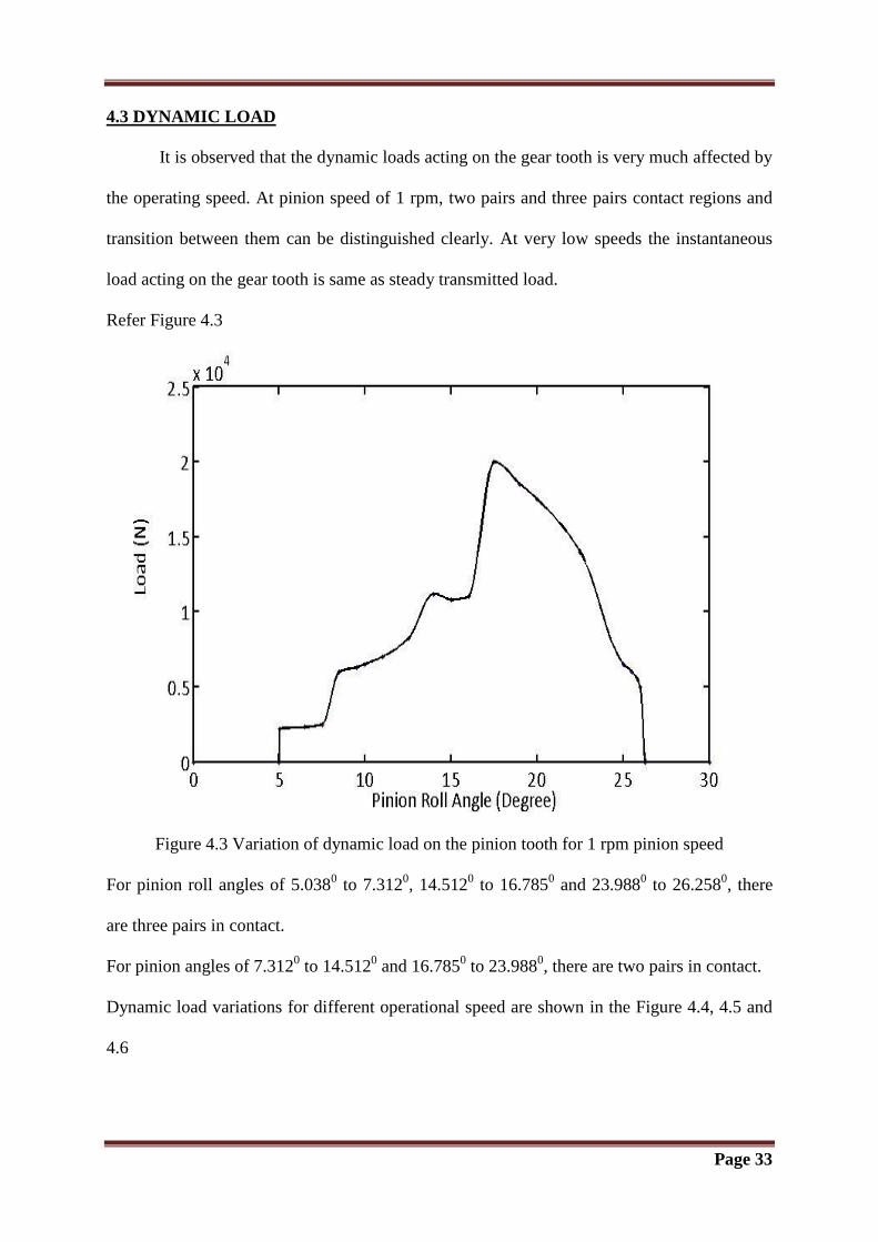
It is observed that the dynamic loads acting on the gear tooth is very much affected by
the operating speed. At pinion speed of 1 rpm, two pairs and three pairs contact regions and
transition between them can be distinguished clearly. At very low speeds the instantaneous
load acting on the gear tooth is same as steady transmitted load.
Refer Figure 4.3
Figure 4.3 Variation of dynamic load on the pinion tooth for 1 rpm pinion speed
For pinion roll angles of 5.0380 to 7.312
0, 14.512
0 to 16.785
0 and 23.988
0 to 26.258
0, there
are three pairs in contact.
For pinion angles of 7.3120 to 14.512
0 and 16.785
0 to 23.988
0, there are two pairs in contact.
Dynamic load variations for different operational speed are shown in the Figure 4.4, 4.5 and
4.6
Page 34
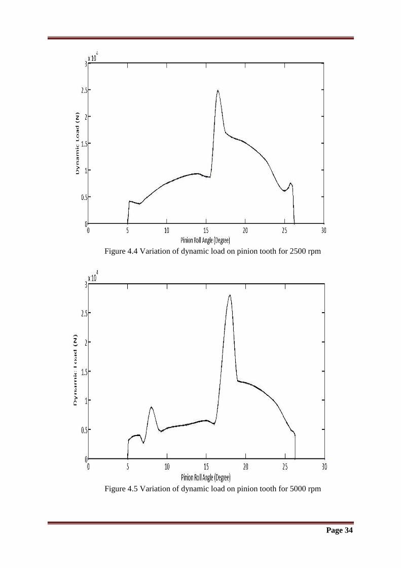
Figure 4.4 Variation of dynamic load on pinion tooth for 2500 rpm
Figure 4.5 Variation of dynamic load on pinion tooth for 5000 rpm
Page 35
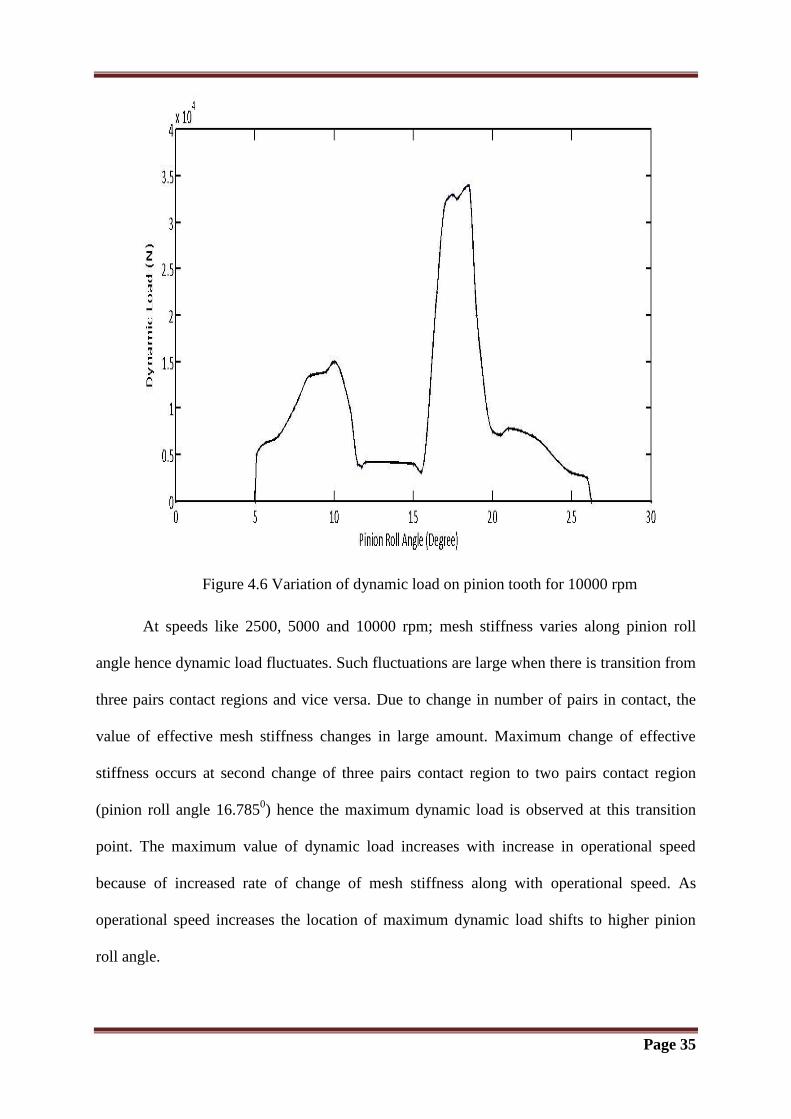
Figure 4.6 Variation of dynamic load on pinion tooth for 10000 rpm
At speeds like 2500, 5000 and 10000 rpm; mesh stiffness varies along pinion roll
angle hence dynamic load fluctuates. Such fluctuations are large when there is transition from
three pairs contact regions and vice versa. Due to change in number of pairs in contact, the
value of effective mesh stiffness changes in large amount. Maximum change of effective
stiffness occurs at second change of three pairs contact region to two pairs contact region
(pinion roll angle 16.7850) hence the maximum dynamic load is observed at this transition
point. The maximum value of dynamic load increases with increase in operational speed
because of increased rate of change of mesh stiffness along with operational speed. As
operational speed increases the location of maximum dynamic load shifts to higher pinion
roll angle.
Page 36
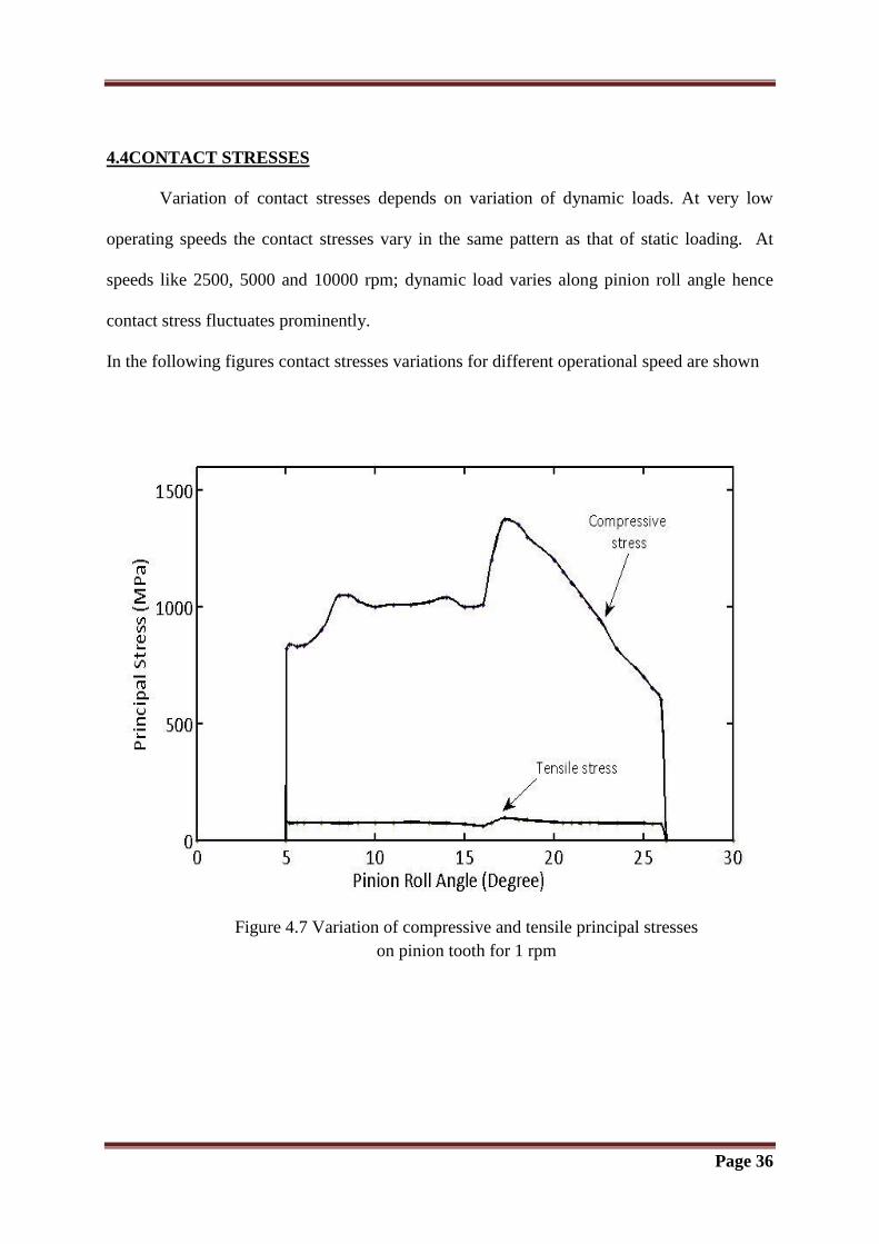
4.4CONTACT STRESSES
Variation of contact stresses depends on variation of dynamic loads. At very low
operating speeds the contact stresses vary in the same pattern as that of static loading. At
speeds like 2500, 5000 and 10000 rpm; dynamic load varies along pinion roll angle hence
contact stress fluctuates prominently.
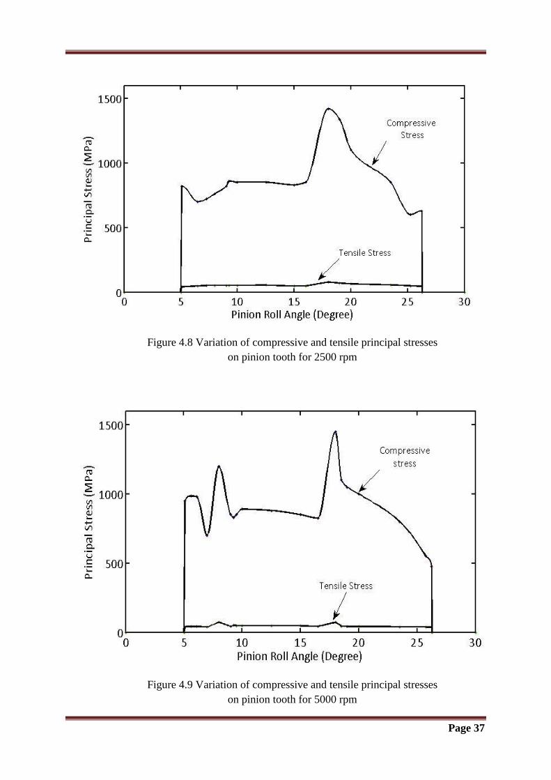
In the following figures contact stresses variations for different operational speed are shown
Figure 4.7 Variation of compressive and tensile principal stresses
on pinion tooth for 1 rpm
Page 37
Figure 4.8 Variation of compressive and tensile principal stresses
on pinion tooth for 2500 rpm
Figure 4.9 Variation of compressive and tensile principal stresses
on pinion tooth for 5000 rpm
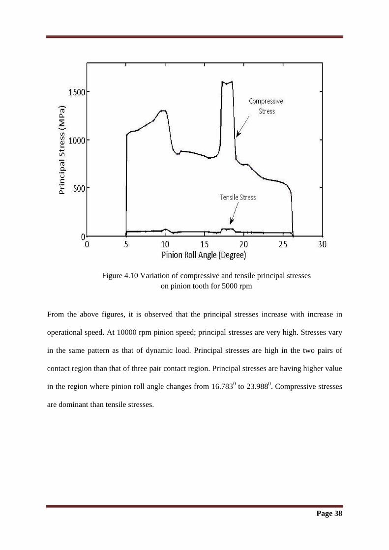
Page 38
Figure 4.10 Variation of compressive and tensile principal stresses
on pinion tooth for 5000 rpm
From the above figures, it is observed that the principal stresses increase with increase in
operational speed. At 10000 rpm pinion speed; principal stresses are very high. Stresses vary
in the same pattern as that of dynamic load. Principal stresses are high in the two pairs of
contact region than that of three pair contact region. Principal stresses are having higher value
in the region where pinion roll angle changes from 16.7830 to 23.988
0. Compressive stresses
are dominant than tensile stresses.

Chapter 5
CONCLUSION & FUTURE SCOPE
Page 39
5.1 CONCLUSION
The present work gives an analytical method for calculation of the tooth load sharing
in high contact ratio spur gear pairs at any point in mesh cycle. It also gives the stiffness
variation of driving gear, driven gear and mesh with respect to pinion roll angle. For dynamic
load analysis of high contact ratio spur gear system, a torsional vibration based model is used.
This gives the effect of operational speed on magnitude of dynamic load acting on pinion
tooth also on the principal stresses acting on pinion tooth. Effect of operational speed on the
location of maximum dynamic load is predicted here.
From the foregoing discussion it is concluded that
Stiffness of the driving gear tooth decreases along the path of contact whereas the
stiffness of the driven gear tooth increases along the path of contact. In general tooth
is more flexible at the outside than it is near the root.
Normal load acting on pinion tooth has maximum value in the two pairs contact
region.
At low speed, the instantaneous load acting on pinion tooth is same as that of static
transmitted load.
Due to change in effective stiffness in second change of three pairs contact zone to
two pair of contact zone, maximum dynamic load and principal stresses are observed
in this region.
Variation of operational speed has an influence on the magnitude of dynamic load
acting on pinion tooth
Location of maximum dynamic load acting on pinion tooth is very much affected by
operational speed.
Page 40
5.2 FUTURE SCOPE
This study can be carried out further including the flexibility of disks, shafts on which
gears are mounted and bearings.
This method of analysis can be applied to other forms of tooth profile like cycloid,
non-involute, non-standard etc. with the proper modification.
This analysis can be extended for other type of gears with composite materials.
Two dimensional and Three Dimensional contact analysis can be done using ANSYS
and then compared with the analytical results.

Chapter 6
REFERENCES
Page 41
6 REFERENCES
[1] W. A. Tuplin, “Gear Tooth Stresses at High Speed”, Proceedings of the Institution of
Mechanical Engineers, 1950, Vol. 163, page 162-175.
[2] J. O. Smith and C. K. Liu, “Stresses due to Tangential and Normal Loads on an Elastic
Solid with Application to some Contact Stress Problems”, Journal of Applied Mechanics,
1953, Vol. 20, page 157.
[3] D. R. Houser and A. Seireg, “Evaluation of Dynamic Factors for Spur and Helical Gears”,
ASME J. Eng. Ind. , 1970, Vol. 92, page 504–514.
[4] L. Wilcox and W. Coleman, “Application of Finite Elements to the Analysis of Gear
Tooth Stresses”, Journal of Manufacturing Science Engineering, 1973, Vol. 95, Issue 4,
page1139-1148.
[5] H.E.Staph, “A Parametric Analysis of High Contact Ratio Spur Gears”, ASLE
Transections, 1976, Vol.19, Issue 3, page 201-215.
[6] R. W. Cornell and W. W. Westervelt, “Dynamic Tooth Loads and Stressing for High
Contact Ratio Spur Gears”, Journal of Mechanical Design, 1978, Vol. 100, Issue 1, page 69-
76.
[7] J.W. Lund, “Critical Speeds, Stability and Response of a Geared Train of Rotors”, ASME
Journal of Mechanical Design, 1978, Vol.100, page 535-538.
[8] R. Kasuba and J. W. Evans, “An Extended Model for Dynamic Loads in Spur Gearing”,
ASME Journal of Mechanical Design, 1981, page 398-409.
[9] A. H. Elkholy, “Tooth Load Sharing in High-Contact Ratio Spur Gears”, Journal of
Mechanical Design, 1985, Vol. 107, Issue1, page11-16.
Page 42
[10] D. C. Yang and J. Y. Lin, “Hertzian Damping, Tooth Friction and Bending Elasticity in
Gear Impact Dynamics”, ASME Journal of Mechanisms, Transmissions and Automation in
Design, 1987, Vol. 109, page 107.
[11] H. Nevzat Ozguven and D. R. Houser, “Dynamic Analysis of High Speed Gears using
Loaded Static Transmission Error”, Journal of Sound and Vibration, 1988, Vol. 125, Issue1,
page 71-83.
[12] A. Kahraman and R. Singh “Error Associated With a Reduced Order Linear Model of a
Spur Gear Pair”, Journal of Sound and Vibration, 1991, Vol. 149, Issue 3, page 495-498.
[13] A. Kahraman, H. N. Ozguven and D. R. Houser, “Dynamic Analysis of Geared Rotor by
Finite Element”, ASME Journal of Mechanical Design, 1992, Vol. 114, Issue 2, page 507-
514.
[14] S. K. Nayak, “Effect of Tooth Stiffness on Dynamic Load on Spur Gear Teeth in Mesh”,
ME Thesis Regional Engineering College, Rourkela, Odisha, 1994.
[15] V. Ramamurti, H. Nayak, Vijayendra and C. Sujatha “Static and Dynamic Analysis of
Spur and Bevel Gears using FEM”, Mechanical Machine Theory, 1998, Vol. 33, Issue 8,
page 1177-1193.
[16] R. G. Parker, S. M. Vijayakar and T. Imajo, “Non-Linear Dynamic Response of a Spur
Gear Pair: Modelling and Experimental Comparisons”, Journal of Sound and Vibration,
2000, Vol. 237, Issue 3, page 435-455.
[17] K. J. Huang and T. S. Liu,“Dynamic Analysis of Spur Gear by Dynamic Stiffness
Method”, Journal of Sound and vibration, 2000, Vol. 234, Issue 2, page 311-329.
Page 43
[18] A.Kapelevich, “Geometry and design of involute spur gears with asymmetric teeth”,
Mechanism and Machine Theory, 2000, Vol.135, page 117-130.
[19] Siu-Tong Choi and Sheng-Yang Mau, “Dynamic Analysis of Geared Rotor-Bearing
Systems by the Transfer Matrix Method”, Journal of Mechanical Design, 2001, Vol. 123,
page 562-568.
[20] Zhang Hua Fong, Ta Wei Chiang and Chieh Wen Tsey, “Mathematical Model for
Parametric Tooth Profile of Spur Gear Using Line of Action”, Mathematical and Computer
Modeling, 2002, Vol. 36, page 603-614.
[21] L. Vedmar and A. Anderson, “A Method to Determine Dynamic Loads on Spur Gear
Teeth and on Bearings”, Journal of Sound and Vibration, 2003, Vol. 267, page 1065–1084.
[22] Rafiq Maliha, Can U. Dogruer and H. Nevzatozguven, “Nonlinear Dynamic Modeling of
Gear Shaft Disk Bearing Systems Using Finite Elements and Describing Functions”,
Transactions of the ASME, 2004, Vol. 126, page 534-541.
[23] Jiande Wang and Ian Howard, “Finite Element Analysis of High Contact Ratio Spur
Gears in Mesh”, Journal of Tribology, 2005, Vol. 127, page 469-483.
[24] Shuting Li, “Finite Element Analysis for Contact Strength and Bending Strength of A
Pair of Spur Gears With Machining Errors, Assembly Errors And Tooth Modifications”,
Mechanism and Machine Theory, 2007, Vol.42, page 88–114.
[25] E. Podzharov, V. Syromyatnikov, J. Navarro and R. Navarro, “Static and Dynamic
Transmission Error in Spur Gears”, The Open Industrial and Manufacturing Engineering
Journal, 2008, Vol. 1, page 37-41.
Page 44
[26] Shuting Li, “Effect of Addendum on Contact Strength, Bending Strength and Basic
Performance Parameters of a Pair of Spur Gears”, Mechanism and Machine Theory,
2008,Vol. 43, page 1557–1584.
[27] F. Karpat, S. E. Osire, K. Cavdar and F. C.Babalik, “Dynamic Analysis of Involute Spur
Gears with Asymmetric Teeth”, International Journal of Mechanical Sciences, 2008, Vol.50,
page 1598–1610.
[28] W. Kim, H. H. Yoo and J. Chung, “Dynamic Analysis for a Pair of Spur Gears with
Translational Motion due to Bearing Deformation”, Journal of Sound and Vibration, 2010,
Vol. 329, page 4409–4421.
[29] M. Ristivojevic, T. Lazovic and A. Vencl, “Studying the Load Carrying Capacity of
Spur Gear Tooth Flanks”, Mechanism and Machine Theory, 2013, Vol.59, page 125–137.
[30] A. F. Rincon, F. Viadero , M. Iglesias, P. Garcia, A. de-Juan and R. Sancibrian, “A
Model for the Study of Meshing Stiffness in Spur Gear Transmissions”, Mechanism and
Machine Theory, 2013, vol. 61, page 30–58.


![[1] involuteΣiii(spur and helical gear design system)Spur...1 [1] involuteΣiii(spur and helical gear design system) 図1.1 involuteΣiii(spur and helical) 1.1 概要 involuteΣⅲ(spur](https://img.pdfslide.net/doc/110x75/5ae0683d7f8b9a97518d2bd7/1-involuteiiispur-and-helical-gear-design-system-spur1-1-involuteiiispur.jpg)