Embed Size (px)
Citation preview

Static and Dynamic Behaviour of the VersaBolt™
Presented by
Denis Champaigne
VP Technical Services MMTI

General Description
• The VersaBolt ™ is designed for ground support conditions that are subject to static or dynamic stresses where conventional bolting techniques are too rigid.
• The bolt is made from a smooth steel bar with either two or three anchors positioned along its length. The end anchor has 4 deformations and the collar anchor has 6 deformations.
• The specialised steel used has both high tensile strength and elongation properties.
• The bolt can be installed in a drilled hole with either resin or cementitious grouts with equally similar properties.
• Once installed, the anchors become fixed and do not move within the grout column. In the event of a rockburst or rock dilation due to squeezing ground, the smooth bar sections between the anchors will elongate.

The Design Elements • In the first phase of the loading process, the bolt is stiff and will behave
similarly to that of a resin rebar however once the yield point is exceeded, the steel plastically deforms allowing for controlled deformation of the rock mass.
• It is these unique design properties that allow the bolt to absorb the energy of either a rockburst or squeezing ground.
• The anchor at the end of the bolt is the most important one. The VersaBolt™ is considered a point anchored bolt therefore the end anchor must support the full tensile capacity of the steel without slipping under all conditions. For this reason, we have added extra deformation in this anchor zone to ensure that even in circumstances where the borehole is enlarged or the bar is installed under less than ideal conditions, the end anchor will still have sufficient capacity to meet or exceed the full tensile strength of the steel. The three anchors are designed to support the full capacity of the steel.

The Design Elements
• The bolt is available in two different bolt diameters, 20mm and 22mm and the number and location of the anchors can be configured depending on the specific needs of the client. The standard bar configuration has three anchors positioned along the anchor bolt and each serves a distinct purpose. The end anchor has four deformations and as described above is fixed. The anchor at the threads is designed to create a rigid zone so that the static or dynamic stress exerted on this anchor zone is transferred via steel stretch to the middle anchor. As a general rule, ground conditions at the collar can be highly fractured and or the drill hole enlarged. For this reason, we have designed the thread anchor with a total of 6 deformations to better ensure that under adverse conditions, the bar in this zone is well anchored. This also eliminates or greatly reduces loading on the threads and plate when the rock dilates

Second Design
• The second configuration comprises of only two anchor points, one at the end and one at the collar.
• When the bar is completely encapsulation up to the collar with resin or cement, the load is transferred to the anchor element at the end of the bolt.
• The longer smooth section of the bolt will allow for more plastic deformation, which further reduces the rigidity of the support.
• This configuration is particularly useful when the mine is experiencing high rock dilation but it can be an interesting consideration under certain dynamic loading conditions as well.

Technical Specifications
* As tested by Canmet
** Based On Mill Test Certificate
Smooth Bar Steel
Specifications 20 mm VersaBolt 22 mm VersaBolt
Minimum Typical Minimum Typical *
Yield Strength 151 kN - 16.9 tons 165 kN - 18 tons 174 kN- 19.6 tons 193 kN - 21.7 tons
Ultimate Tensile Strength 201 KN - 20.7 tons 237 kN - 26.6 tons 233 kN - 26 tons 259 kN - 29 tons
Elongation 17% 24% ** 17% 24%**
Threaded Steel Section
Minimum Typical Minimum Typical *
Yield Strength 133 kN - 13.4 tons 160 kN - 18.5 tons 154 kN - 17.3 tons 193 kN - 21.7 tons
Ultimate Tensile Strength 185 KN - 21 tons 213 kN - 24 tons 214 kN - 24 tons 259 kN - 29.1 tons

Canmet Dynamic and Static Testing Methods
• There is two testing methods, continuous or split tube
• Using the continuous method the load is dropped onto threads whereas in the split tube method, the steel tube is split between two anchors and the smooth bar section absorbs the load
• The split tube method is the generally accepted testing method for this style of bolt

Dynamic Capacity as Tested by Canmet
* As tested by Canmet
General Specifications 20 mm VersaBolt 22 mm VersaBolt
Dynamic Capacity Split Tube * Split Tube *
Canmet Testing 37 kJ > 50 kJ

Static Behaviour
0
50
100
150
200
250
300
0 50 100 150 200
Load
[kN
]
Displacement [mm]
22 mm VersaBolt™ 1 Metre Smooth Bar Section
Maximum Force = 259 kN
Maximum Displacement = 205.72 mm
193 kN Yield

22mm Split Tube Static Testing
0
100
200
300
0 60 120 180
Lo
ad
(kN
)
Displacement (mm)
Data_Plate Displacement Data_Toe Displacement
Elongation = 165 mm
Maximum Load = 270 kN

Static Behaviour
0
50
100
150
200
250
300
0 20 40 60 80 100 120
Lo
ad
[k
N]
Displacement [mm]
196 kN Yield
22mm VersaBolt™ Threaded End Test
196 kN Yield
Maximum Force = 250 kN
196 kN Yield Maximum Displacement = 86.55 mm

20mm VersaBolt™ 20 kJ Dynamic Drop Test

20mm VersaBolt™ 40 kJ Dynamic Drop Test

22mm VersaBolt™ 42 kJ Split Tube Drop Test, 1.5 Metre Anchor Spacing
0
10
20
30
40
50
60
70
0
50
100
150
200
250
300
350
0 20 40 60 80 100 120 140 160 180
En
erg
y (
kJ
)
Lo
ad
(k
N)
Displacement (mm)
Specimen Versa-2 Drop 1 Mass = 2897 kg; Height = 1.5 m
Energy = 42 kJ; Velocity = 5.42 m/s
Impact Load Absorbed Energy
Absorbed Energy = 44.29

22mm VersaBolt™ 50 kJ Split Tube Drop Test, 1.6 Metre Anchor Spacing
0
10
20
30
40
50
60
70
0
50
100
150
200
250
300
350
0 20 40 60 80 100 120 140 160 180 200
En
erg
y (
kJ
)
Lo
ad
(k
N)
Displacement (mm)
Specimen Versa-3 Drop 1 Mass = 2897 kg; Height = 1.76 m
Energy = 50 kJ; Velocity = 5.88 m/s
Impact Load Absorbed Energy
Absorbed Energy = 53.28

22mm 40 kJ Drop Test in 38mm Pipe

20mm x 7’ VersaBolt™ Pull Test
2
4
6
8
10
12
14
16
18
20
22
24
0 10 20 30 40 50 60 70 80 90
Test 1
Test 2
Test 3
Test 4
Test 5
Test 6
Displacement (mm)
Load
(to
n)

Point Anchor Versus Full Encapsulation Pull Test
2
4
6
8
10
12
14
16
18
20
22
24
0 10 20 30 40 50 60 70 80 90
20mm x 7’ (2.1m)
Test 1
Test 2
Test 3
Test 4
Test 5
Test 6
Displacement (mm)
Load
(to
n)

Static Behaviour • Rebar is considered a very stiff support, assuming it is fully encapsulated and
won’t allow much rock displacement before either the threaded section or the encapsulated bar breaks.
• Ground support requirements change over time. Initially the rock may be self supporting however as mining progresses and stress increases, the rock mass may change to a “broken” rock mass followed by failure due to overstressing .
• The VersaBolt™ behaves similarly to any other fully encapsulated bolt up until the yield point of the steel is reached, with relative displace of only 6 to 8mm. It should be noted that the steel yield point of a 20mm VersaBolt™ is approximately 18 tons (160 kN) which is slightly less than the ultimate tensile strength of a 20mm rebar.
• A two anchor design would be sufficient stiff for most mines initial static requirements however over time as stresses increase the bolt will have the capacity to deform accordingly.
• When squeezing ground is the primary consideration, a two anchor would definitely be better suited than a three anchor design.
• VersaBolt™ however can be configured to provide more or less total displacement by varying the number of anchors, bolt length of the support or increasing the diameter of the steel.
• Canmet’s static testing of a smooth bar section versus an equal length threaded bar section demonstrates the importance of having the collar anchor encapsulated so that the overall elongation potential of the steel is maximised.

Dynamic Stiffness • Dynamic stiffness is the amount of deformation or displacement you gets from a given
energy input. Rebar would be considered to have a high dynamic stiffness, lower is better.
• As the energy input increases, so to does peak and average loading
• A longer smooth bar section between the anchors results in higher elongation for a given energy input which results in lower overall average loading of the steel
• The VersaBolt relies on steel stretch to absorb energy and steel stretch doesn’t occur until the yield point of the steel is reached. Making a bolt larger simply increases the stress level at which the bolt starts to stretch.
• The surface support will always be subjected to the energy of a rockburst. Generally the first metre of rock is what will be ejected and needs to be contained while the energy is transferred to the bolt.
• It is conceivable that we could make a bolt with an energy absorption capacity of 100 kJ yet the overall support would fail during a rockburst for the simple reason it is too stiff dynamically i.e. didn’t displace sufficiently.
• The surface support needs to be strong enough to transfer this energy to the without it failing, hence why it is important that which ever support is used, the surface support is equal to the task.
• The easiest way to reduce the dynamic stiffness of a VersaBolt, is to eliminate the central anchor so that it allows more displacement for a given input energy.
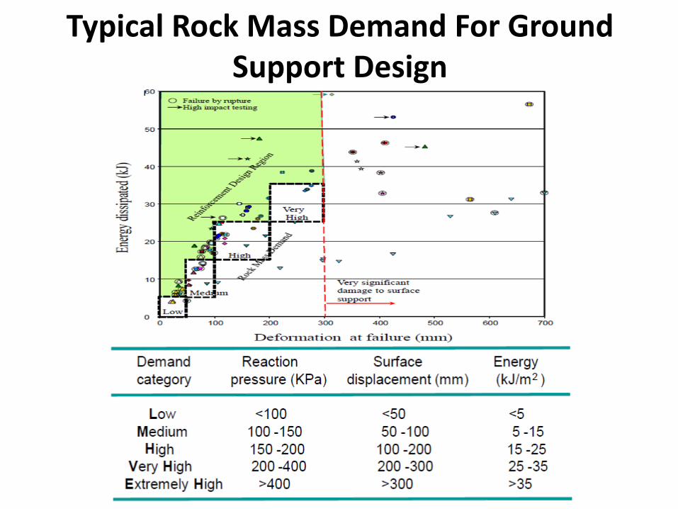
Typical Rock Mass Demand For Ground Support Design

Dynamic Support Calculation For A 1 Metre Depth Of Failure
0
50
100
150
200
250
300
350
1 2 3 4 5 6
Ejection velocity (m/s) Energy Demand (kj/bolt) Req Bolt Displacement (mm)
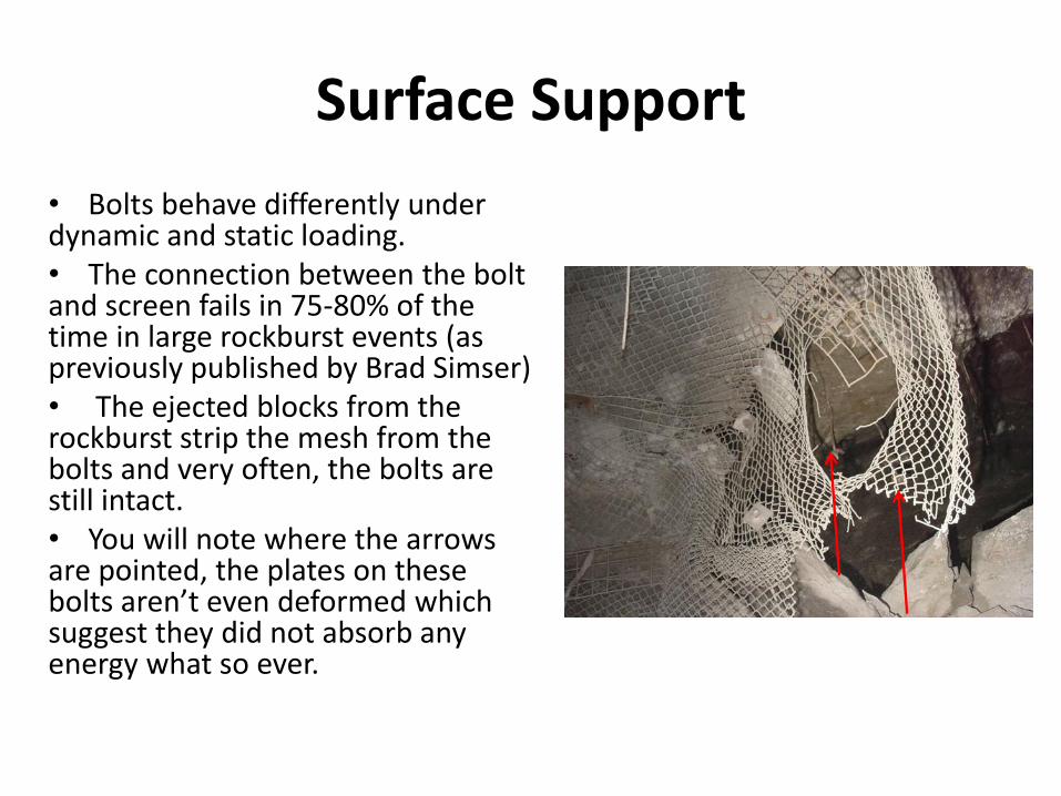
Surface Support
• Bolts behave differently under dynamic and static loading. • The connection between the bolt and screen fails in 75-80% of the time in large rockburst events (as previously published by Brad Simser) • The ejected blocks from the rockburst strip the mesh from the bolts and very often, the bolts are still intact. • You will note where the arrows are pointed, the plates on these bolts aren’t even deformed which suggest they did not absorb any energy what so ever.
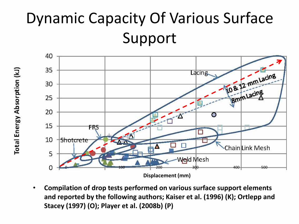
Dynamic Capacity Of Various Surface Support
• Compilation of drop tests performed on various surface support elements and reported by the following authors; Kaiser et al. (1996) (K); Ortlepp and Stacey (1997) (O); Player et al. (2008b) (P)
0 100 200 300 400 500
Displacement (mm)

Dynamic Stiffness and Surface Support Capacity
• Every bolt design has varying static and dynamic stiffness • Surface support needs to be matched to the dynamic behaviour
of the bolt. • The surface support also needs to match the anticipated energy
demand that it will be subjected too. • As energy input increases, the bolt displacement need to
increase exponentially – A dynamically stiff bolt will require a stronger and more
flexible surface support so that it survives a seismic event – Conversely, if the bolt has a lower dynamic stiffness, the
surface support will not be subjected to the same loading • Energy absorption in kJ is not the only consideration when
evaluating a bolt design, overall behaviour is as important
Comments & Conclusions • Ground support requirements change over time. Initially the rock may be self
supporting however as mining progresses and stress increases, the rock mass may change to a “broken” rock mass followed by failure due to overstressing .
• A VersaBolt™ would be sufficient stiff for most mines initial static requirements however, over time as stresses increase, the bolt will have the capacity to deform accordingly.
• Due to the stiff behaviour of the steel up to the yield point, the VersaBolt™ can be considered a rigid support even with only two anchors
• A larger diameter bolt is better for squeezing ground but not necessarily for dynamic energy absorption since the steel doesn’t start to absorb energy until the yield point of the steel is exceeded.
• We can make a bolt with a 100 kJ capacity however if the bolt can’t displace or elongate sufficiently, the rock and the surface support will fail.
• Bolt spacing can be modified to match the anticipated energy demand and displacement.
• The two anchor bolt design, with the longer centre smooth bar section, will allow much more displacement in squeezing ground conditions and when subjected to a seismic event, the longer smooth bar section in the centre will also reduce the dynamic stiffness of the bolt.
• Last but not least, the collar anchor should always be encapsulated with resin to ensure that in the event of a rockburst, the first metre of rock being ejected is well anchored to the bar and can transfer the load the next anchor point

Thank You For Your Time