Embed Size (px)
Citation preview

Static and Seismic design of Steel Structures
cubus Hellas LtdSoftware · Consulting Services
Pre-and postprocessor of STATIK-5Steel profiles from the database ofFAGUS-5User defined built-up sections (double Lsections etc)User defined I or H welded sectionsArea, line and point loads on load surfacesEquivalent static and dynamic modal ana-lysisSeismic displacements and rotations verifi-cationSeismic loads and masses generation
Automatic combinations of various actions(gravity, snow, wind loads, crane loads,etc)Design of every cross section type accordingto Eurocode 3 for:
− Shear− Biaxial bending with axial force− Flexural buckling− Lateral - torsional buckling
Hollow section joint design according toAnnex-K of Eurocode 3Interfaces for CAD programs

Cross section checks
Cross section classification
Full plastic calculation and determination ofthe neutral axis using the algorithm ofFAGUS-5Support for Class 4 sections
- Calculation of the effective cross section prop-erties
- Eccentricities and additional moments due toasymmetry
Steel profiles
Support for the rolled steel sections of theFAGUS-5 libraryI and H steel profiles: IPE, IPE0, IPEV, HEAA,HEA, HEB, HEM, DIL, HER, HHD, HP, HXHollow sections: RHS, TPS, MSH, CHS,ROR, RGL, RGM, RGSEqual and unequal leg angles (LNP)UNP and UAP sections
Build-up sections
Double L sections with equal and unequallegs
Double UNP or UAP sectionsUser defined welded built-up sections usingthe graphical interface of FAGUS-5
Cross-section-level checks
ShearBiaxial bending with axial force
Member-level checks
Flexural bucklingLateral-torsional bucklingAccurate determination of the parametets ky,kz, kLT taking into account the bending mo-ment diagramsEspecially for angle sections: calculation ofthe strength reduction due to the eccentric-ity of the connection (for welded and boltedconnections)
Hollow section joint checks
Automatic recognition of the joint type anddesign according to Annex K of Eurocode 3Constructional detailsCAD interface
General
Graphical representation of all the checks inthe STATIK-5 environmentOptional calculation of the first adequate sec-tion
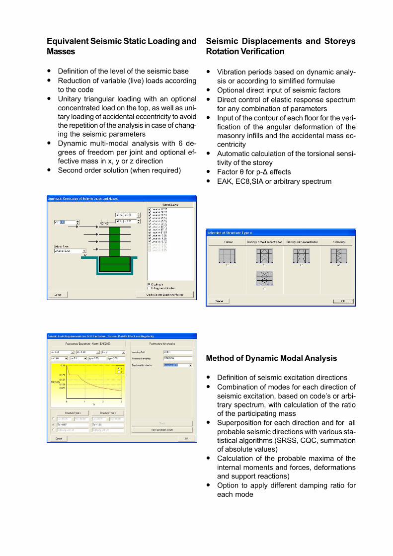
Seismic Displacements and StoreysRotation Verification
Vibration periods based on dynamic analy-sis or according to simlified formulaeOptional direct input of seismic factorsDirect control of elastic response spectrumfor any combination of parametersInput of the contour of each floor for the veri-fication of the angular deformation of themasonry infills and the accidental mass ec-centricityAutomatic calculation of the torsional sensi-tivity of the storeyFactor è for p-Ä effectsEAK, EC8,SIA or arbitrary spectrum
Equivalent Seismic Static Loading andMasses
Definition of the level of the seismic baseReduction of variable (live) loads accordingto the codeUnitary triangular loading with an optionalconcentrated load on the top, as well as uni-tary loading of accidental eccentricity to avoidthe repetition of the analysis in case of chang-ing the seismic parametersDynamic multi-modal analysis with 6 de-grees of freedom per joint and optional ef-fective mass in x, y or z directionSecond order solution (when required)
Method of Dynamic Modal Analysis
Definition of seismic excitation directionsCombination of modes for each direction ofseismic excitation, based on code’s or arbi-trary spectrum, with calculation of the ratioof the participating massSuperposition for each direction and for allprobable seismic directions with various sta-tistical algorithms (SRSS, CQC, summationof absolute values)Calculation of the probable maxima of theinternal moments and forces, deformationsand support reactions)Option to apply different damping ratio foreach mode

Design of trusses
Graphic input of the trusses, the purlins andof all the bracing systemsGrouping of the trusses through a specialmanagement menuCross section groupingDesign for any combination of actionsAutomatic calculation of the buckling lengthsOptional direct input of the buckling lengths
Design for:- Shear- Biaxial bending with axial force- Flexural buckling- Lateral torsional bucklingOptional automatic calculation of the firstadequate section and update of the input filesGraphical representation of the check resultsPurlin checks in graphical form
Column design
User utilities
Automatic identification of the continuity ofcolumns from storey to storeyCross section groupingGrouping through a specific managementmenuAutomatic calculation of the buckling lengthsin both local directionsOptional direct input of the buckling lengthsFrame stability:
- Frame imperfection in all directions- Solution using 2nd order theoryGraphical representations of the beams con-nected to each column in both local dire-tions

Design
Design for basic and seismic actionsAutomatic calculation of the first adequatesection and update of the input filesDesign for:
- Shear- Biaxial bending with axial force- Flexural buckling- Lateral torsional buckling
Results
Graphical representation of the check resultsText files with all the necessary checks andreferences to the equations of Eurocode 3
Bracing systems design
User utilities
Grouping of the bracing systems through aspecial management menuCross section groupingAutomatic calculation of the buckling lengthsOptional direct input of the buckling lengthsFrame stability checks using frame imper-fections in all directions
Design
Design for basic and seismic actionsAutomatic calculation of the first adequatesection and update of the input filesDesign for:
- Shear- Biaxial bending with axial force- Flexural buckling- Lateral torsional buckling
Results
Graphical representation of the check resultsText files with all the necessary checks andreferences to the equations of Eurocode 3
Beam design
User utilities
Automatic identification of the continuity ofbeams and of the faces of vertical membersGrouping of continuous beams through aspecial management menuCross section groupingAutomatic calculation of the buckling lengthsOptional direct input of the buckling lengthsLateral torsional buckling:
- Graphical input of the lateral support points- Graphical input of the parameters k and kw- automatic calculation of the parameters C1,
C2, C3 from the bending moments diagram

Design
Design for basic and seismic actionsAutomatic calculation of the first adequatesection and update of the input filesDesign for:
- Shear- Biaxial bending with axial force- Flexural buckling- Lateral torsional buckling
cubus Hellas LtdSoftware · Consulting Services
CUBUS HELLAS Ltd TH. SOFOULI 7 Str. 154 51 Í. PSYCHIKOÔEL: (210) 6722 –360 –366 –389 FAX : (210) 6722382e-mail: [email protected] www.cubushellas.gr
Results
Graphical representation of the check resultsText files with all the necessary checks andreferences to the equations of Eurocode 3