Embed Size (px)
Citation preview
12
CHAPTER OUTLINE
12.1 The Conditions for Equilibrium12.2 More on the Center of Gravity12.3 Examples of Rigid Objects in Static Equilibrium12.4 Elastic Properties of Solids
Static Equilibrium and Elasticity
ANSWERS TO QUESTIONS
Q12.1 When you bend over, your center of gravity shifts forward.Once your CG is no longer over your feet, gravity contributesto a nonzero net torque on your body and you begin to rotate.
Q12.2 Yes, it can. Consider an object on a spring oscillating back andforth. In the center of the motion both the sum of the torquesand the sum of the forces acting on the object are (separately)zero. Again, a meteoroid flying freely through interstellar spacefeels essentially no forces and keeps moving with constantvelocity.
Q12.3 No—one condition for equilibrium is that F∑ = 0 . For this to
be true with only a single force acting on an object, that forcewould have to be of zero magnitude; so really no forces act onthat object.
Q12.4 (a) Consider pushing up with one hand on one side of a steering wheel and pulling downequally hard with the other hand on the other side. A pair of equal-magnitude oppositely-directed forces applied at different points is called a couple.
(b) An object in free fall has a non-zero net force acting on it, but a net torque of zero about itscenter of mass.
Q12.5 No. If the torques are all in the same direction, then the net torque cannot be zero.
Q12.6 (a) Yes, provided that its angular momentum is constant.
(b) Yes, provided that its linear momentum is constant.
Q12.7 A V-shaped boomerang, a barstool, an empty coffee cup, a satellite dish, and a curving plastic slideat the edge of a swimming pool each have a center of mass that is not within the bulk of the object.
Q12.8 Suspend the plywood from the nail, and hang the plumb bob from the nail. Trace on the plywoodalong the string of the plumb bob. Now suspend the plywood with the nail through a different pointon the plywood, not along the first line you drew. Again hang the plumb bob from the nail and tracealong the string. The center of gravity is located halfway through the thickness of the plywoodunder the intersection of the two lines you drew.
349
350 Static Equilibrium and Elasticity
Q12.9 The center of gravity must be directly over the point where the chair leg contacts the floor. Thatway, no torque is applied to the chair by gravity. The equilibrium is unstable.
Q12.10 She can be correct. If the dog stands on a relatively thick scale, the dog’s legs on the ground mightsupport more of its weight than its legs on the scale. She can check for and if necessary correct forthis error by having the dog stand like a bridge with two legs on the scale and two on a book ofequal thickness—a physics textbook is a good choice.
Q12.11 If their base areas are equal, the tall crate will topple first. Its center of gravity is higher off the inclinethan that of the shorter crate. The taller crate can be rotated only through a smaller angle before itscenter of gravity is no longer over its base.
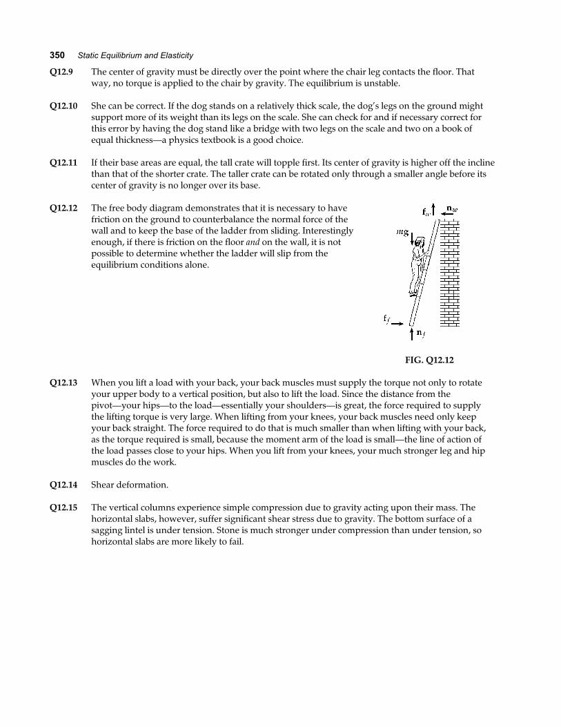
Q12.12 The free body diagram demonstrates that it is necessary to havefriction on the ground to counterbalance the normal force of thewall and to keep the base of the ladder from sliding. Interestinglyenough, if there is friction on the floor and on the wall, it is notpossible to determine whether the ladder will slip from theequilibrium conditions alone.
FIG. Q12.12
Q12.13 When you lift a load with your back, your back muscles must supply the torque not only to rotateyour upper body to a vertical position, but also to lift the load. Since the distance from thepivot—your hips—to the load—essentially your shoulders—is great, the force required to supplythe lifting torque is very large. When lifting from your knees, your back muscles need only keepyour back straight. The force required to do that is much smaller than when lifting with your back,as the torque required is small, because the moment arm of the load is small—the line of action ofthe load passes close to your hips. When you lift from your knees, your much stronger leg and hipmuscles do the work.
Q12.14 Shear deformation.
Q12.15 The vertical columns experience simple compression due to gravity acting upon their mass. Thehorizontal slabs, however, suffer significant shear stress due to gravity. The bottom surface of asagging lintel is under tension. Stone is much stronger under compression than under tension, sohorizontal slabs are more likely to fail.
Chapter 12 351
SOLUTIONS TO PROBLEMS
Section 12.1 The Conditions for Equilibrium
P12.1 To hold the bat in equilibrium, the player must exert both aforce and a torque on the bat to make
F Fx y∑ ∑= = 0 and τ∑ = 0
F Fy∑ = ⇒ − =0 10 0 0. N , or the player must exert a net
upward force of F = 10 0. N
To satisfy the second condition of equilibrium, the player mustexert an applied torque τ a to make
τ τ∑ = − =a 0 600 10 0 0. . m Na fa f . Thus, the required torque is
τ a = + ⋅6 00. N m or 6 00. N m counterclockwise⋅
F
O
10.0 N
0.600 m0.600 m
FIG. P12.1
P12.2 Use distances, angles, and forces as shown. The conditions ofequilibrium are:
F F R F
F F R
F F F
y y y g
x x x
y g x
∑∑
∑
= ⇒ + − =
= ⇒ − =
= ⇒ − FHGIKJ − =
0 0
0 0
02
0τ θ θ θcos cos sin
l
θ
Fy
Fx
Ry
Rx
O
Fg
FIG. P12.2
P12.3 Take torques about P.
τ p bn d m g d m gd m gx∑ = − +LNMOQP + +LNM
OQP + − =0 1 22 2
0
We want to find x for which n0 0= .
xm g m g d m g
m gm m d m
mb b=
+ +=
+ +1 1 2
2
1 1 2
2
b g b g x
CG
nO nP
O
m1m2P
d
m g1 m g2m gb
2
FIG. P12.3
352 Static Equilibrium and Elasticity
Section 12.2 More on the Center of Gravity
P12.4 The hole we can count as negative mass
xm x m x
m mCG =−−
1 1 2 2
1 2
Call σ the mass of each unit of pizza area.
xR
R
xR
R R
R
R
CG
CG
=− −
−
= =
σπ σπ
σπ σπ
22
22
22
2
834
0
6
c h c hc h
P12.5 The coordinates of the center of gravity of piece 1 are
x1 2 00= . cm and y1 9 00= . cm .
The coordinates for piece 2 are
x2 8 00= . cm and y2 2 00= . cm .
The area of each piece is
A1 72 0= . cm2 and A2 32 0= . cm2 .
And the mass of each piece is proportional to the area. Thus,
4.00 cm
18.0 cm
12.0 cm
4.00 cm
1
2
FIG. P12.5
xm xm
i i
iCG
2 2
2 2
cm cm cm cm
cm cm cm= =
+
+=∑
∑72 0 2 00 32 0 8 00
72 0 32 03 85
. . . .
. ..
e ja f e ja f
and
ym ym
i i
iCG
2 2
2
cm cm cm cm
cm cm= =
+=∑
∑72 0 9 00 32 0 2 00
1046 85
. . . ..
e ja f e ja f.
Chapter 12 353
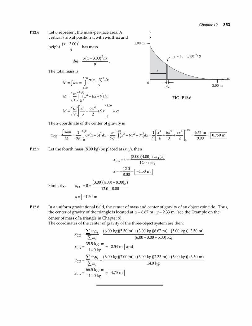
P12.6 Let σ represent the mass-per-face area. Avertical strip at position x, with width dx and
height x − 3 00
9
2.a f has mass
dmx dx
=−σ 3 00
9
2.a f.
The total mass is
M dmx dx
M x x dx
Mx x
x
x
= =−
= FHGIKJ − +
= FHGIKJ − +LNM
OQP
=
z zz
=
σ
σ
σσ
39
96 9
9 36
29
2
0
3 00
2
0
3 00
3 2
0
3 00
a f
e j
.
.
.
x
dx0
3.00 m
x
y
1.00 m
y = (x — 3.00)2/9
FIG. P12.6
The x-coordinate of the center of gravity is
xxdm
Mx x dx x x x dx
x x xCG
m9.00
m= = − = − + = − +LNM
OQP
= =z z z19
39
6 919 4
63
92
6 750 7502
0
3 003 2
0
3 00 4 3 2
0
3 00
σσ
σσ
a f e j. . .
..
P12.7 Let the fourth mass (8.00 kg) be placed at (x, y), then
xm x
m
x
CG
m
= =+
+
= − = −
03 00 4 00
12 012 08 00
1 50
4
4
. ..
..
.
a fa f a f
Similarly, yy
CG = =+
+0
3 00 4 00 8 00
12 0 8 00
. . .
. .
a fa f b g
y = −1 50. m
P12.8 In a uniform gravitational field, the center of mass and center of gravity of an object coincide. Thus,the center of gravity of the triangle is located at x = 6 67. m , y = 2 33. m (see the Example on thecenter of mass of a triangle in Chapter 9).The coordinates of the center of gravity of the three-object system are then:
xm xm
x
ym ym
y
i i
i
i i
i
CG
CG
CG
CG
kg m kg m kg m
kg
kg m14.0 kg
m and
kg m kg m kg m
kg
kg m14.0 kg
m
= =+ + −
+ +
=⋅
=
= =+ + +
=⋅
=
∑∑
∑∑
6 00 5 50 3 00 6 67 5 00 3 50
6 00 3 00 5 00
35 52 54
6 00 7 00 3 00 2 33 5 00 3 50
14 0
66 54 75
. . . . . .
. . .
..
. . . . . .
.
..
b ga f b ga f b ga fa f
b ga f b ga f b ga f
354 Static Equilibrium and Elasticity
Section 12.3 Examples of Rigid Objects in Static Equilibrium
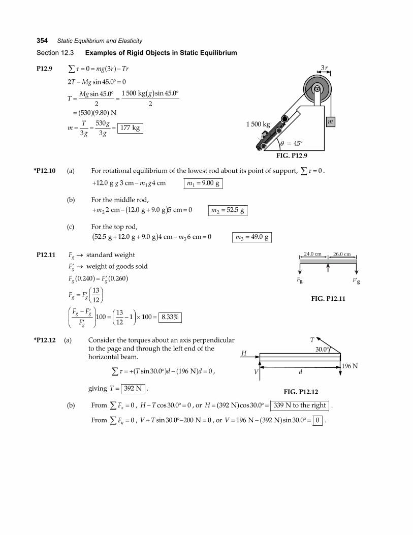
P12.9 τ∑ = = −0 3mg r Tra f2 45 0 0
45 02
1 500 45 0
2530 9 80
3530
3177
T Mg
TMg g
mTg
gg
− °=
=°=
°
=
= = =
sin .
sin . sin .
.
kg
N
kg
b g
a fa fm
3r
θ = 45°
1 500 kg
FIG. P12.9
*P12.10 (a) For rotational equilibrium of the lowest rod about its point of support, τ∑ = 0 .
+ −12 0 1. g 3 cm 4 cmg m g m1 9 00= . g
(b) For the middle rod,+ − + =m2 2 12 0 9 0 5 0 cm g g cm. .b g m2 52 5= . g
(c) For the top rod,52 5 12 0 9 0 4 6 03. . . g g g cm cm+ + − =b g m m3 49 0= . g
P12.11 Fg → standard weight
′ →Fg weight of goods sold
F F
F F
F F
F
g g
g g
g g
g
0 240 0 260
1312
1001312
1 100 8 33%
. .
.
a f a f= ′
= ′ FHGIKJ
− ′
′
FHG
IKJ = −FHG
IKJ × =
24.0 cm 26.0 cm
Fg F′g
FIG. P12.11
*P12.12 (a) Consider the torques about an axis perpendicularto the page and through the left end of thehorizontal beam.
τ∑ = + ° − =T d dsin .30 0 196 0a f a f N ,
giving T = 392 N .
H
d196 N
V
T30.0°
FIG. P12.12
(b) From Fx =∑ 0 , H T− °=cos .30 0 0 , or H = °=392 30 0 339 N N to the righta fcos . .
From Fy∑ = 0 , V T+ °− =sin .30 0 200 0 N , or V = − °=196 392 30 0 0 N Na fsin . .
Chapter 12 355
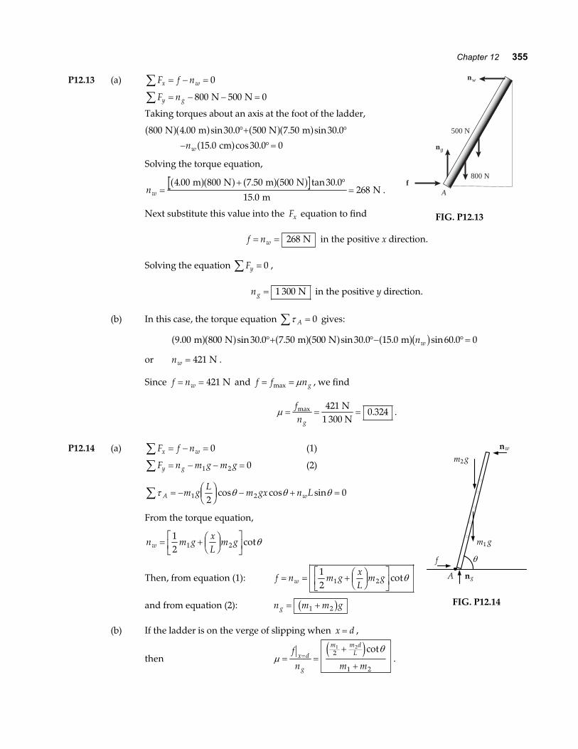
P12.13 (a) F f nx w∑ = − = 0
F ny g∑ = − − =800 500 0 N N
Taking torques about an axis at the foot of the ladder,
800 4 00 30 0 500 7 50 30 0
15 0 30 0 0
N m N m
cm
a fa f a fa fa f
. sin . . sin .
. cos .
°+ °
− °=nw
Solving the torque equation,
nw =+ °
=4 00 800 7 50 500 30 0
15 0268
. . tan .
.
m N m N
m N
a fa f a fa f.
Next substitute this value into the Fx equation to find
ng
f
nw
500 N
800 N
A
FIG. P12.13
f nw= = 268 N in the positive x direction.
Solving the equation Fy∑ = 0 ,
ng = 1 300 N in the positive y direction.
(b) In this case, the torque equation τ A =∑ 0 gives:
9 00 800 30 0 7 50 500 30 0 15 0 60 0 0. sin . . sin . . sin . m N m N ma fa f a fa f a fb g°+ °− °=nw
or nw = 421 N .
Since f nw= = 421 N and f f ng= =max µ , we find
µ = = =fng
max .421
0 324 N
1 300 N.
P12.14 (a) F f nx w∑ = − = 0 (1)
F n m g m gy g∑ = − − =1 2 0 (2)
τ θ θ θA wm gL
m gx n L∑ = − FHGIKJ − + =1 22
0cos cos sin
From the torque equation,
n m gxL
m gw = + FHGIKJ
LNM
OQP
12 1 2 cotθ
Then, from equation (1): f n m gxL
m gw= = + FHGIKJ
LNM
OQP
12 1 2 cotθ
and from equation (2): n m m gg = +1 2b g(b) If the ladder is on the verge of slipping when x d= ,
then µθ
= =+
+=
f
n m mx d
g
m m dL
1 22
1 2
e jcot.
f
A ng
m g1
m g2
nw
θ
FIG. P12.14
356 Static Equilibrium and Elasticity
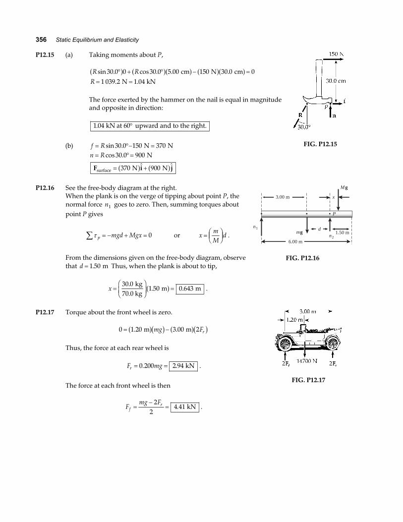
P12.15 (a) Taking moments about P,
R RR
sin . cos . . .. .
30 0 0 30 0 5 00 150 30 0 01 039 2 1 04
° + ° − == =a f a fa f a fa f cm N cm
N kN
The force exerted by the hammer on the nail is equal in magnitudeand opposite in direction:
1 04. kN at 60 upward and to the right.°
(b) f R= °− =sin .30 0 150 370 N Nn R= °=
= +
cos .30 0 900
370 900
N
N NsurfaceF i ja f a f
FIG. P12.15
P12.16 See the free-body diagram at the right.When the plank is on the verge of tipping about point P, thenormal force n1 goes to zero. Then, summing torques aboutpoint P gives
τ p mgd Mgx∑ = − + = 0 or xmM
d= FHGIKJ .
From the dimensions given on the free-body diagram, observethat d = 1 50. m Thus, when the plank is about to tip,
x =FHG
IKJ =
30 01 50 0 643
.. .
kg70.0 kg
m ma f .
6.00 m
Mg
mgn2
n1
x3.00 m
P
d1.50 m
FIG. P12.16
P12.17 Torque about the front wheel is zero.
0 1 20 3 00 2= −. . m ma fb g a fb gmg Fr
Thus, the force at each rear wheel is
F mgr = =0 200 2 94. . kN .
The force at each front wheel is then
Fmg F
fr=
−=
22
4 41. kN .
FIG. P12.17
Chapter 12 357
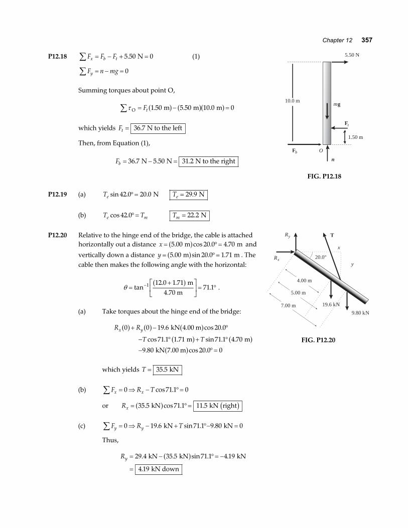
P12.18 F F Fx b t∑ = − + =5 50 0. N (1)
F n mgy∑ = − = 0
Summing torques about point O,
τO m m m∑ = − =Ft 1 50 5 50 10 0 0. . .a f a fa f
which yields Ft = 36 7. N to the left
Then, from Equation (1),
Fb = − =36 7 5 50 31 2. . . N N N to the right
10.0 m
5.50 N
1.50 m
mg
Ft
Fb O
n
FIG. P12.18
P12.19 (a) Te sin . .42 0 20 0°= N Te = 29 9. N
(b) T Te mcos .42 0°= Tm = 22 2. N
P12.20 Relative to the hinge end of the bridge, the cable is attachedhorizontally out a distance x = °=5 00 20 0 4 70. cos . . m ma f and
vertically down a distance y = °=5 00 20 0 1 71. sin . . m ma f . Thecable then makes the following angle with the horizontal:
θ =+L
NMOQP = °−tan
. ..1 12 0 1 71
71 1a f m
4.70 m.
(a) Take torques about the hinge end of the bridge:
R R
T Tx y0 0 19 6 20 0
71 1 1 71 71 1 4 70
9 80 20 0 0
a f a f a fa f a fa f
+ − °
− ° + °
− °=
. cos .
cos . . sin . .
. cos .
kN 4.00 m
m m
kN 7.00 m
which yields T = 35 5. kN
(b) F R Tx x∑ = ⇒ − °=0 71 1 0cos .
or Rx = °=35 5 71 1 11 5. cos . . kN kN righta f b g
(c) F R Ty y∑ = ⇒ − + °− =0 19 6 71 1 9 80 0. sin . . kN kN
Thus,
Ry = − °= −
=
29 4 35 5 71 1 4 19
4 19
. . sin . .
.
kN kN kN
kN down
a f
x
y
T
20.0°Rx
Ry
9.80 kN
19.6 kN
4.00 m
5.00 m
7.00 m
FIG. P12.20
358 Static Equilibrium and Elasticity
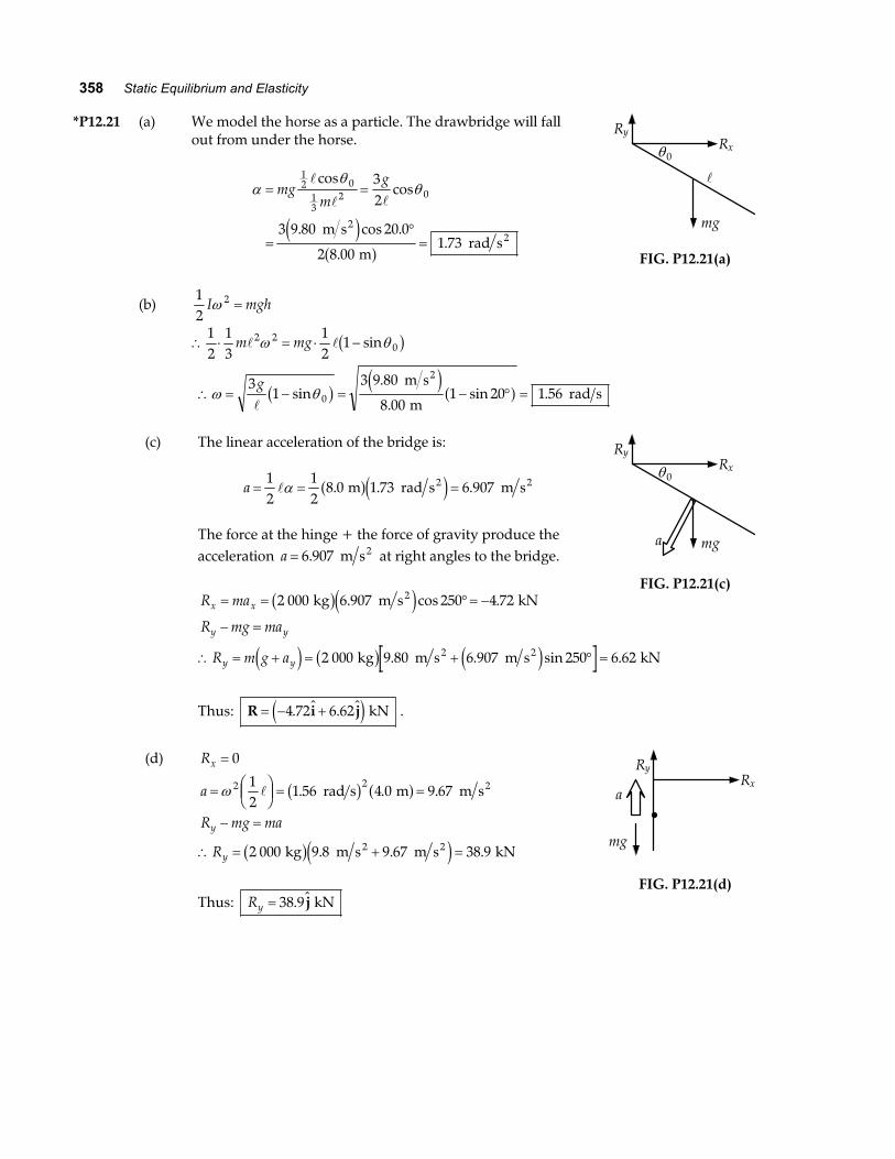
*P12.21 (a) We model the horse as a particle. The drawbridge will fallout from under the horse.
αθ
θ= =
=°=
mgm
g12 0
13
2 032
3 9 80 20 0
2 8 001 73
coscos
. cos .
..
m s
m rad s
22e j
a f
(b)12
2I mghω =
∴ ⋅ = ⋅ −12
13
12
12 20m mgω θsinb g
RyRx
mg
θ0
FIG. P12.21(a)
∴ = − = − ° =ω θ3
13 9 80
8 001 20 1 560
gsin
.
.sin .b g e j a f m s
m rad s
2
(c) The linear acceleration of the bridge is:
a = = =12
12
8 0 1 73 6 907α . . . m rad s m s2 2a fe j
The force at the hinge + the force of gravity produce theacceleration a = 6 907. m s2 at right angles to the bridge.
R max x= = °= −2 000 6 907 250 4 72 kg m s kN2b ge j. cos .
R mg may y− =
RyRx
mg
θ0
a
FIG. P12.21(c)
∴ = + = + ° =R m g ay ye j b g e j2 000 9 80 6 907 250 6 62 kg m s m s kN2 2. . sin .
Thus: R i j= − +4 72 6 62. .e j kN .
(d) Rx = 0
a
R mg ma
R
y
y
= FHGIKJ = =
− =
∴ = + =
ω 2 212
1 56 4 0 9 67
2 000 9 8 9 67 38 9
. . .
. . .
rad s m m s
kg m s m s kN
2
2 2
b g a f
b ge j
Thus: Ry = 38 9. j kN
RyRx
mg
a
FIG. P12.21(d)
Chapter 12 359
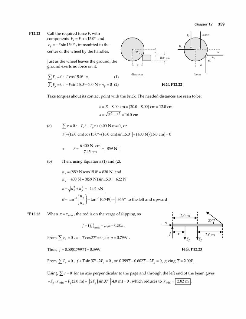
P12.22 Call the required force F, withcomponents F Fx = °cos .15 0 andF Fy = − °sin .15 0 , transmitted to the
center of the wheel by the handles.
Just as the wheel leaves the ground, theground exerts no force on it.
Fx∑ = 0 : F nxcos .15 0°− (1)
Fy∑ = 0 : − °− + =F nysin .15 0 400 0 N (2)
RRR
nxny
Fx
Fy 400 N
b
8.00 cm
distances forces
aa
b
a
FIG. P12.22
Take torques about its contact point with the brick. The needed distances are seen to be:
b R
a R b
= − = − =
= − =
8 00 20 0 8 00 12 0
16 02 2
. . . .
.
cm cm cm
cm
a f
(a) τ∑ = 0 : − + + =F b F a ax y 400 0 Na f , or
F − °+ ° + =12 0 15 0 16 0 15 0 400 16 0 0. cos . . sin . . cm cm N cma f a f a fa f
so F =⋅
=6 400
859 N cm
7.45 cm N
(b) Then, using Equations (1) and (2),
nx = °=859 15 0 830 N Na fcos . and
ny = + °=400 859 15 0 622 N N Na fsin .
n n n
n
n
x y
y
x
= + =
=FHGIKJ = = °− −
2 2
1 1
1 04
0 749 36 9
.
tan tan . .
kN
to the left and upwardθ a f
*P12.23 When x x= min , the rod is on the verge of slipping, so
f f n ns s= = =b gmax.µ 0 50 .
From Fx∑ = 0 , n T− °=cos37 0 , or n T= 0 799. .
Thus, f T T= =0 50 0 799 0 399. . .a f
37°
x f
n
F g F g
2.0 m
2.0 m
FIG. P12.23
From Fy∑ = 0 , f T Fg+ °− =sin37 2 0 , or 0 399 0 602 2 0. .T T Fg− − = , giving T Fg= 2 00. .
Using τ∑ = 0 for an axis perpendicular to the page and through the left end of the beam gives
− ⋅ − + ° =F x F Fg g gmin . sin .2 0 2 37 4 0 0 m ma f e j a f , which reduces to xmin .= 2 82 m .
360 Static Equilibrium and Elasticity
P12.24 xL
=34
If the CM of the two bricks does not lie over the edge, thenthe bricks balance.
If the lower brick is placed L4
over the edge, then the
second brick may be placed so that its end protrudes 34L
over the edge.
L
x
FIG. P12.24
P12.25 To find U, measure distances and forces from point A. Then, balancing torques,
0 750 29 4 2 25. . .a f a fU = U = 88 2. N
To find D, measure distances and forces from point B. Then, balancing torques,
0 750 1 50 29 4. . .a f a fa fD = D = 58 8. N
Also, notice that U D Fg= + , so Fy =∑ 0 .
*P12.26 Consider forces and torques on the beam.
Fx∑ = 0 : R Tcos cosθ − °=53 0
Fy∑ = 0 : R Tsin sinθ + °− =53 800 0 N
τ∑ = 0 : T xsin53 8 600 200 4 0° − − =a f a f a f m N N m
(a) Then Tx
x=+ ⋅
°= +
600 80053
93 9 125 N N m8 m
N m Nsin
.b g . As x increases from 2 m, this expression
grows larger.
(b) From substituting back,
R x
R x
cos . cos
sin . sin
θ
θ
= + °
= − + °
93 9 125 53
800 93 9 125 53 N
Dividing, tansincos
tancos
θθθ
= = − °+°
RR x
53800
93 9 125 53 N
. +a f
tan tanθ = °+
−FHG
IKJ53
323 4
1x
As x increases the fraction decreases and θ decreases .
continued on next page
Chapter 12 361
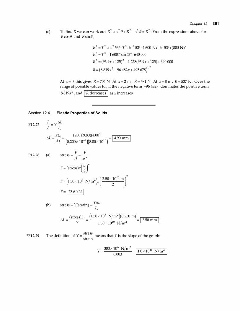
(c) To find R we can work out R R R2 2 2 2 2cos sinθ θ+ = . From the expressions above forR cosθ and R sinθ ,
R T T T
R T T
R x x
R x x
2 2 2 2 2 2
2 2
2 2
2 1 2
53 53 1 600 53 800
1 600 53 640 000
93 9 125 1 278 93 9 125 640 000
8 819 96 482 495 678
= °+ °− °+
= − °+
= + − + +
= − +
cos sin sin
sin
. .
N Na f
a f a fe j
At x = 0 this gives R = 704 N . At x = 2 m , R = 581 N . At x = 8 m , R = 537 N . Over therange of possible values for x, the negative term −96 482x dominates the positive term
8 819 2x , and R decreases as x increases.
Section 12.4 Elastic Properties of Solids
P12.27FA
YL
Li=
∆
∆LFLAY
i= =× ×
=−
200 9 80 4 00
0 200 10 8 00 104 90
4 10
a fa fa fe je j
. .
. .. mm
P12.28 (a) stress = =FA
Frπ 2
Fd
F
F
= FHGIKJ
= ××F
HGIKJ
=
stress
N m2.50 10 m
2
kN
2-2
a f
e j
π
π
2
1 50 10
73 6
2
82
.
.
(b) stress = =YY LLi
straina f ∆
∆LL
Yi= =
×
×=
stress N m m
N m mm
2
2
a f e ja f1 50 10 0 250
1 50 102 50
8
10
. .
..
*P12.29 The definition of Y =stressstrain
means that Y is the slope of the graph:
Y =×
= ×300 10
0 0031 0 10
611 N m
N m2
2
.. .
362 Static Equilibrium and Elasticity
P12.30 Count the wires. If they are wrapped together so that all support nearly equal stress, the numbershould be
20 0100
. kN0.200 kN
= .
Since cross-sectional area is proportional to diameter squared, the diameter of the cable will be
1 100 1 mm cma f ~ .
P12.31 From the defining equation for the shear modulus, we find ∆x as
∆xhfSA
= =×
× ×= ×
−
−−
5 00 10 20 0
3 0 10 14 0 102 38 10
3
6 45
. .
. ..
m N
N m m m
2 2
e ja fe je j
or ∆x = × −2 38 10 2. mm .
P12.32 The force acting on the hammer changes its momentum according to
mv F t mvi f+ =∆a f so Fm v v
tf i
=−
∆.
Hence, F =− −
= ×30 0 10 0 20 0
0 1108 18 103. . .
..
kg m s m s
s N .
By Newton’s third law, this is also the magnitude of the average force exerted on the spike by thehammer during the blow. Thus, the stress in the spike is:
stress = =×
= ×FA
8 18 101 97 10
3
4
72
..
N N m
0.023 0 m
2
π b g
and the strain is: strain = =×
×= × −stress N m
N m
2
2Y1 97 1020 0 10
9 85 107
105.
.. .
P12.33 (a) F A=
= × ×
×
−
a fa fe j e j
stress
m N m
= 3.14 10 N
2
4
π 5 00 10 4 00 103 2 8. .
(b) The area over which the shear occurs is equal tothe circumference of the hole times its thickness.Thus,
A r t= = × ×
= ×
− −
−
2 2 5 00 10 5 00 10
1 57 10
3 3
4
π πa f e je j. .
.
m m
m2
F
3.0 ft
t
AAA
FIG. P12.33
So, F A= = × × = ×−a f e je jStress m N m N2 21 57 10 4 00 10 6 28 104 8 4. . . .
Chapter 12 363
P12.34 Let the 3.00 kg mass be mass #1, with the 5.00 kg mass, mass # 2. Applying Newton’s second law toeach mass gives:
m a T m g1 1= − (1) and m a m g T2 2= − (2)
where T is the tension in the wire.
Solving equation (1) for the acceleration gives: aT
mg= −
1,
and substituting this into equation (2) yields: mm
T m g m g T2
12 2− = − .
Solving for the tension T gives
Tm m g
m m=
+= =
2 2 3 00 5 00 9 80
8 0036 81 2
2 1
. . .
..
kg kg m s
kg N
2b gb ge j.
From the definition of Young’s modulus, YFL
A Li=
∆a f , the elongation of the wire is:
∆LTLYA
i= =× ×
=−
36 8 2 00
2 00 10 2 00 100 029 3
11 3 2
. .
. ..
N m
N m m mm
2
a fa fe j e jπ
.
P12.35 Consider recompressing the ice, which has a volume 1 09 0. V .
∆∆
P BV
Vi= −FHGIKJ =
− × −= ×
2 00 10 0 090
1 091 65 10
98
. .
..
N m N m
22e ja f
*P12.36 BP PV
VVV
i
i
= − = −∆ ∆
∆∆
(a) ∆∆
VPVB
i= − = −×
×= −
1 13 10 1
0 21 100 053 8
8
10
.
..
N m m
N m m
2 3
23e j
(b) The quantity of water with mass 1 03 103. × kg occupies volume at the bottom
1 0 053 8 0 946 m m m3 3 3− =. . . So its density is 1 03 10
1 09 103
3..
×= ×
kg0.946 m
kg m33 .
(c) With only a 5% volume change in this extreme case, liquid water is indeed nearlyincompressible.
*P12.37 Part of the load force extends the cable and part compresses the column by the same distance ∆ :
FY A Y A
F
A A
A
s s
s
Y A Y AA A
A
s s
s
= +
=+
=+
= ×
× − ×
−
∆ ∆
∆8 500
8 60 10
0 162 4 0 161 4
4 3 2520 10 0 012 7
4 5 75
4
2 2 10 2
N
m
7 1010π π. .
..
.
.
e ja f
b ga f
364 Static Equilibrium and Elasticity
Additional Problems
*P12.38 (a) The beam is perpendicular to the wall, since 3 4 52 2 2+ = . Then sinθ =4 m5 m
; θ = °53 1. .
(b) τ hinge∑ = 0 : + − =T sinθ 3 250 0 m N 10 ma f a fT =
°= ×
2 50053 1
1 04 103 Nm3 m
Nsin .
.
(c) xTk
= =×
×=
1 04 100 126
3..
N8.25 10 N m
m3
The cable is 5.126 m long. From the law of cosines,
4 5 126 3 2 3 5 126
3 5 126 42 3 5 126
51 2
2 2 2
12 2 2
= + −
=+ −
= °−
. . cos
cos.
..
a fa f
a fa f
θ
θ
αθ
4 m 5.126 m
3 m
FIG. P12.38
(d) From the law of sines, the angle the hinge makes with the wall satisfies sin.
sin .α5 126
51 24 m m
=°
sin .
sin . .
.
α
τ
=
=
+ °− =
= ×
∑0 998 58
0
3 51 2 250 0 998 0
1 07 103
hinge
m N 10 m 58
N
T
T
a f a fa f
(e) x =×
×=
1 07 100 129
3..
N8.25 10 N m
m3
θ =+ −
= °−cos.
..1
2 2 23 5 129 42 3 5 129
51 1a fa f(f) Now the answers are self-consistent:
sin .sin .
.
sin . .
.
.
.
α
θ
=°=
°− =
= ×=
= °
5 12951 1
40 998
3 51 1 250 0 998 0
1 07 100 129 5
51 1
3
m m
51
m N 10 m 51
N m
T
Tx
a f a fa f
P12.39 Let nA and nB be the normal forces at the points ofsupport.
Choosing the origin at point A with Fy∑ = 0 and τ∑ = 0,
we find:
n n g gA B+ − × − × =8 00 10 3 00 10 04 4. .e j e j and
− × − × + =3 00 10 15 0 8 00 10 25 0 50 0 04 4. . . . .e jb g e jb g a fg g nB
A B
15.0 m15.0 m50.0 m50.0 m
FIG. P12.39
The equations combine to give nA = ×5 98 105. N and bB = ×4 80 105. N .
Chapter 12 365
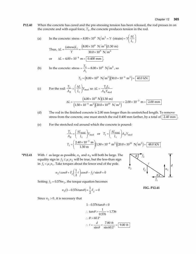
P12.40 When the concrete has cured and the pre-stressing tension has been released, the rod presses in onthe concrete and with equal force, T2 , the concrete produces tension in the rod.
(a) In the concrete: stress = × = ⋅ =FHGIKJ8 00 106. N m strain2 Y Y
LLi
a f ∆
Thus, ∆LL
Yi= =
×
×
stress N m m
N m
2
2
a f e ja f8 00 10 1 50
30 0 10
6
9
. .
.
or ∆L = × =−4 00 10 0 4004. . m mm .
(b) In the concrete: stress = = ×TAc
2 68 00 10. N m2 , so
T26 48 00 10 50 0 10 40 0= × × =−. . . N m m kN2 2e je j
(c) For the rod: TA
LL
YR i
2 =FHGIKJ
∆steel so ∆L
T LA Y
i
R= 2
steel
∆L =×
× ×= × =
−−
4 00 10 1 50
1 50 10 20 0 102 00 10 2 00
4
4 103
. .
. .. .
N m
m N m m mm
2 2
e ja fe je j
(d) The rod in the finished concrete is 2.00 mm longer than its unstretched length. To removestress from the concrete, one must stretch the rod 0.400 mm farther, by a total of 2 40. mm .
(e) For the stretched rod around which the concrete is poured:
TA
LL
Y TLL
A Y
T
R i iR
11
1
34 102 40 10
1 50 10 20 0 10 48 0
=FHG
IKJ =
FHG
IKJ
=×F
HGIKJ × × =
−−
∆ ∆totalsteel
totalsteel
2 2
or
m1.50 m
m N m kN.
. . .e je j
*P12.41 With as large as possible, n1 and n2 will both be large. Theequality sign in f ns2 2≤ µ will be true, but the less-than signin f ns1 1< µ . Take torques about the lower end of the pole.
n F fg2 212
0cos cos sinθ θ θ+ FHGIKJ − =
Setting f n2 20 576= . , the torque equation becomes
n Fg2 1 0 57612
0− + =. tanθa f
f1
f2
n1n2 Fg
θ
θ
d
FIG. P12.41
Since n2 0> , it is necessary that
1 0 576 01
0 5761 736
60 17 80
60 19 00
− <
∴ > =
∴ > °
∴ = <°=
. tan
tan.
.
.
sin.
sin ..
θ
θ
θ
θd ft
ft
366 Static Equilibrium and Elasticity
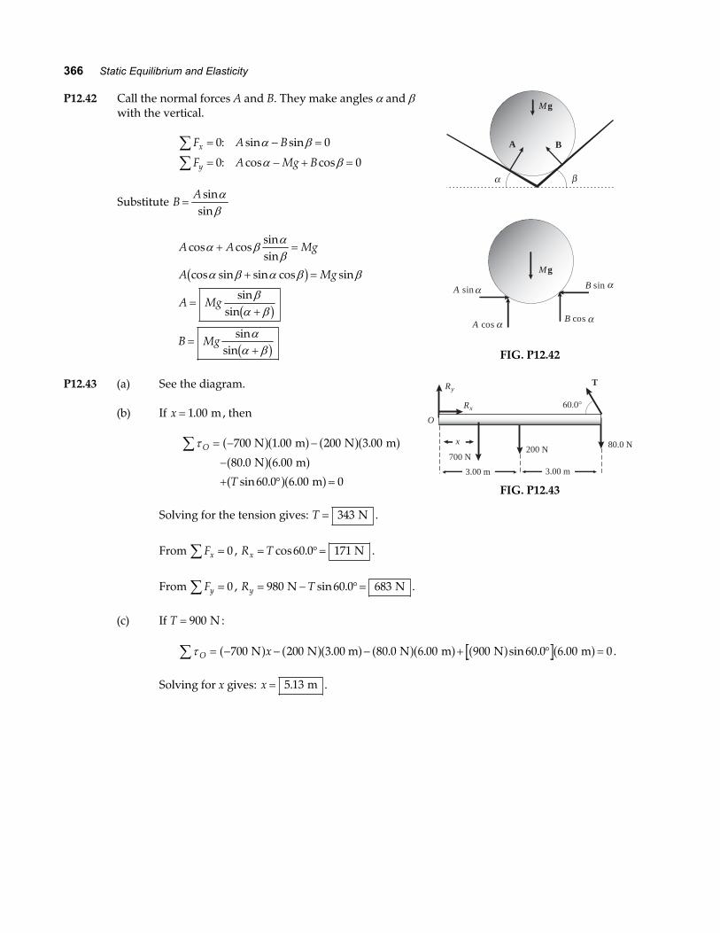
P12.42 Call the normal forces A and B. They make angles α and βwith the vertical.
F A B
F A Mg Bx
y
∑∑
= − =
= − + =
0 0
0 0
: sin sin
: cos cos
α β
α β
Substitute BA
=sin
sinαβ
A A Mg
A Mg
A Mg
B Mg
cos cossinsin
cos sin sin cos sin
sinsin
sinsin
α βαβ
α β α β β
βα β
αα β
+ =
+ =
=+
=+
b g
b g
b g
Mg
A B
α β
Mg
A sin B sin
A cosB cos
α
α α
α
FIG. P12.42
P12.43 (a) See the diagram.
(b) If x = 1 00. m, then
τO
T
∑ = − −
−
+ ° =
700 1 00 200 3 00
80 0 6 00
60 0 6 00 0
N m N m
N m
m
a fa f a fa fa fa fa fa f
. .
. .
sin . .
Solving for the tension gives: T = 343 N .
Ry
x
3.00 m
O
3.00 m
Rx 60.0°
T
700 N200 N 80.0 N
FIG. P12.43
From Fx∑ = 0 , R Tx = °=cos .60 0 171 N .
From Fy∑ = 0 , R Ty = − °=980 60 0 683 N Nsin . .
(c) If T = 900 N :
τO x∑ = − − − + ° =700 200 3 00 m 80 0 6 00 900 60 0 6 00 0 N N N m N ma f a fa f a fa f a f a f. . . sin . . .
Solving for x gives: x = 5 13. m .
Chapter 12 367
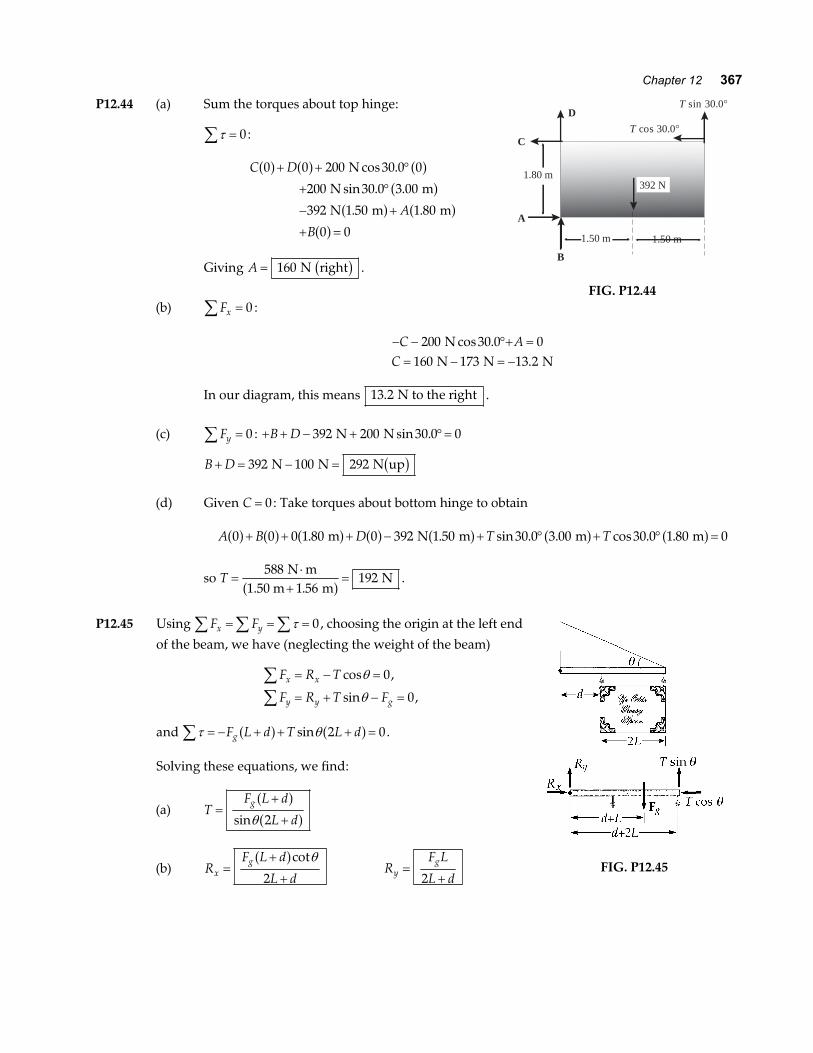
P12.44 (a) Sum the torques about top hinge:
τ∑ = 0:
C D
A
B
0 0 200 30 0 0
200 30 0 3 00
392 1 50 1 80
0 0
a f a f a fa f
a f a fa f
+ + °
+ °
− +
+ =
N
N m
N m m
cos .
sin . .
. .
Giving A = 160 N rightb g .
1.50 m 1.50 m
392 N1.80 m
C
D
T cos 30.0°
T sin 30.0°
A
B
FIG. P12.44(b) Fx∑ = 0 :
− − °+ == − = −
C AC
200 30 0 0160 173 13 2
N N N N
cos ..
In our diagram, this means 13 2. N to the right .
(c) Fy∑ = 0 : + + − + °=B D 392 200 30 0 0 N N sin .
B D+ = − =392 100 292 N N N upb g
(d) Given C = 0: Take torques about bottom hinge to obtain
A B D T T0 0 0 1 80 0 392 1 50 30 0 3 00 30 0 1 80 0a f a f a f a f a f a f a f+ + + − + ° + ° =. . sin . . cos . . m N m m m
so T =⋅
+=
5881 56
192 N m
1.50 m m N
.a f .
P12.45 Using F Fx y∑ ∑ ∑= = =τ 0, choosing the origin at the left end
of the beam, we have (neglecting the weight of the beam)
F R T
F R T Fx x
y y g
∑∑
= − =
= + − =
cos ,
sin ,
θ
θ
0
0
and τ θ∑ = − + + + =F L d T L dg a f a fsin 2 0.
Solving these equations, we find:
(a) TF L d
L dg=
+
+
a fa fsinθ 2
(b) RF L d
L dxg=
+
+
a fcotθ
2R
F L
L dyg=+2
FIG. P12.45
368 Static Equilibrium and Elasticity
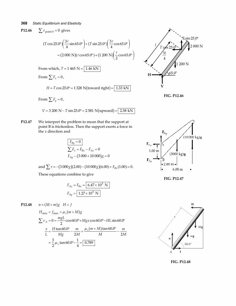
P12.46 τ point 0∑ = 0 gives
T Tcos . sin . sin . cos .
cos . cos .
25 034
65 0 25 034
65 0
2 000 65 0 1 2002
65 0
° °FHG
IKJ + ° °F
HGIKJ
= ° + °FHG
IKJ
a f a f
b ga f b g N N
From which, T = =1 465 1 46 N kN.
From Fx∑ = 0 ,
H T= °= =cos . .25 0 1 328 1 33 N toward right kNb g
From Fy∑ = 0 ,
V T= − °= =3 200 25 0 2 581 2 58 N N upward kNsin . .b g
H
V
65.0°
1 200 N
l 2 000 N
3 4 l
T sin . 25 0 °
T cos . 25 0 °
FIG. P12.46
P12.47 We interpret the problem to mean that the support atpoint B is frictionless. Then the support exerts a force inthe x direction and
F
F F F
F g
By
x Bx Ax
Ay
=
= − =
− + =
∑0
0
3 000 10 000 0b g
and τ∑ = − − + =3 000 2 00 10 000 6 00 1 00 0g g FBxb ga f b ga f a f. . . .
These equations combine to give
F F
F
Ax Bx
Ay
= = ×
= ×
6 47 10
1 27 10
5
5
.
.
N
N
FIG. P12.47
P12.48 n M m g= +a f H f=
H f m M gmgL
Mgx HL
xL
HMg
mM
m MM
mM
s
A
s
s
max max
cos . cos . sin .
tan . tan .
tan . .
= = +
= = °+ °− °
=°− =
+ °−
= °− =
∑
µ
τ
µ
µ
a f
a f0
260 0 60 0 60 0
60 02
60 02
32
60 014
0 789n
f
H
A
60.0°
mg
x
Mg
FIG. P12.48
Chapter 12 369
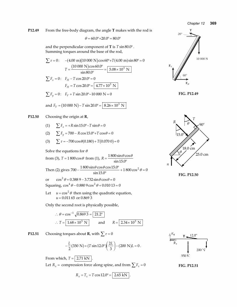
P12.49 From the free-body diagram, the angle T makes with the rod is
θ = °+ °= °60 0 20 0 80 0. . .
and the perpendicular component of T is T sin .80 0° .Summing torques around the base of the rod,
τ∑ = 0: − °+ °=4 00 10 000 60 4 00 80 0. cos . sin m N ma fb g a fT
T =°
°= ×
10 000 60 0
80 05 08 103 N
Nb gcos .
sin ..
Fx∑ = 0 : F TH − °=cos .20 0 0
F TH = °= ×cos . .20 0 4 77 103 N
Fy∑ = 0 : F TV + °− =sin .20 0 10 000 0 N
and F TV = − °= ×10 000 20 0 8 26 103 N Nb g sin . .
FV
T
60°
20°
FH
10 000 N
FIG. P12.49
P12.50 Choosing the origin at R,
(1) F R Tx∑ = + °− =sin . sin15 0 0θ
(2) F R Ty∑ = − °+ =700 15 0 0cos . cosθ
(3) τ θ∑ = − + =700 0 180 0 070 0 0cos . .a f b gT
Solve the equations for θ
from (3), T = 1 800 cosθ from (1), R =°
1 80015 0
sin cossin .
θ θ
Then (2) gives 7001 800 15 0
15 01 800 02−
°°
+ =sin cos cos .
sin .cos
θ θθ
or cos . . sin cos2 0 388 9 3 732 0θ θ θ+ − =Squaring, cos . cos .4 20 880 9 0 010 13 0θ θ− + =
Let u = cos2 θ then using the quadratic equation,u = 0 011 65. or 0.869 3
Only the second root is physically possible,
∴ = = °
∴ = × = ×
−θ cos . .
. .
1
3 3
0 869 3 21 2
1 68 10 2 34 10T R N and N
θ
θ
25.0 cm
90° T
n
15.0°
18.0 cm
R
FIG. P12.50
P12.51 Choosing torques about R, with τ∑ = 0
− + ° FHGIKJ − =
LT
LL
2350 12 0
23
200 0 N Na f a f a fsin . .
From which, T = 2 71. kN .
Let Rx = compression force along spine, and from Fx∑ = 0
R T Tx x= = °=cos . .12 0 2 65 kN .
FIG. P12.51
370 Static Equilibrium and Elasticity
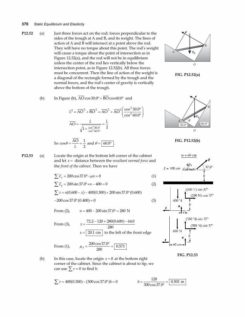
P12.52 (a) Just three forces act on the rod: forces perpendicular to thesides of the trough at A and B, and its weight. The lines ofaction of A and B will intersect at a point above the rod.They will have no torque about this point. The rod’s weightwill cause a torque about the point of intersection as inFigure 12.52(a), and the rod will not be in equilibriumunless the center of the rod lies vertically below theintersection point, as in Figure 12.52(b). All three forcesmust be concurrent. Then the line of action of the weight isa diagonal of the rectangle formed by the trough and thenormal forces, and the rod’s center of gravity is verticallyabove the bottom of the trough.
A
B
Fg
O
FIG. P12.52(a)
(b) In Figure (b), AO BOcos . cos .30 0 60 0°= ° and
L
L L
2 2 2 2 22
2
30 060 0
30 060 0
1 22
2
= + = +°°
FHG
IKJ
=+
=°°
AO BO AO AO
AO
cos .cos .
cos .cos .
So cosθ = =AOL
12
and θ = °60 0. .
A
B
Fg
O
θ30.0° 60.0°
FIG. P12.52(b)
P12.53 (a) Locate the origin at the bottom left corner of the cabinetand let x = distance between the resultant normal force andthe front of the cabinet. Then we have
F nx∑ = °− =200 37 0 0cos . µ (1)
F ny = °+ − =∑ 200 37 0 400 0sin . (2)
τ∑ = − − + °n x0 600 400 0 300 200 37 0 0 600. . sin . .a f a f a f− ° =200 37 0 0 400 0cos . .a f (3)
From (2), n = − °=400 200 37 0 280sin . N
From (3), x =− + −72 2 120 280 0 600 64 0
280. . .a f
x = 20 1. cm to the left of the front edge
From (1), µ k =°=
200 37 0280
0 571cos .
.
(b) In this case, locate the origin x = 0 at the bottom rightcorner of the cabinet. Since the cabinet is about to tip, wecan use τ∑ = 0 to find h:
FIG. P12.53
τ∑ = − ° =400 0 300 300 37 0 0. cos .a f a fh h =°=
120300 37 0
0 501cos .
. m
Chapter 12 371
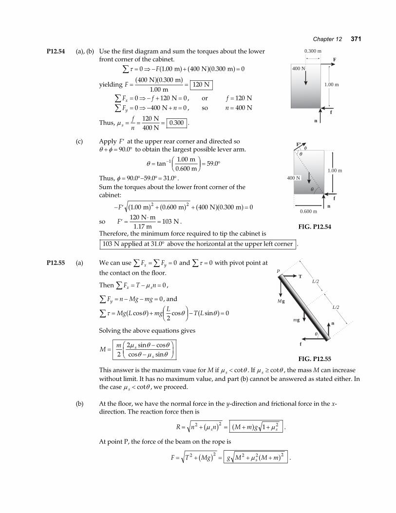
P12.54 (a), (b) Use the first diagram and sum the torques about the lowerfront corner of the cabinet.
τ∑ = ⇒ − + =0 1 00 400 0 300 0F . . m N ma f a fa fyielding F = =
400 0 3001 00
120 N m
m N
a fa f..
F fx∑ = ⇒ − + =0 120 0 N , or f = 120 NF ny∑ = ⇒ − + =0 400 0 N , so n = 400 N
Thus, µ sfn
= = =120
0 300 N
400 N. .
(c) Apply ′F at the upper rear corner and directed soθ φ+ = °90 0. to obtain the largest possible lever arm.
θ = FHG
IKJ = °−tan
..1 1 00
59 0 m
0.600 mThus, φ = °− °= °90 0 59 0 31 0. . . .Sum the torques about the lower front corner of thecabinet:
− ′ + + =F 1 00 0 600 400 0 300 02 2. . . m m N ma f a f a fa fso ′ =
⋅=F
120103
N m1.17 m
N .
Therefore, the minimum force required to tip the cabinet is
400 N
n
f
F
0.300 m
1.00 m
nf
1.00 m
0.600 m
400 N
θ
θ
φF’
FIG. P12.54
103 N applied at 31.0 above the horizontal at the upper left corner° .
P12.55 (a) We can use F Fx y∑ ∑= = 0 and τ∑ = 0 with pivot point at
the contact on the floor.
Then F T nx s∑ = − =µ 0 ,
F n Mg mgy = − − =∑ 0, and
τ θ θ θ∑ = + FHGIKJ − =Mg L mg
LT Lcos cos sina f a f
20
Solving the above equations gives
Mm s
s=
−−
FHG
IKJ2
2µ θ θθ µ θsin cos
cos sin
n
f
P
θ
mg
T
MgL/2
L/2
FIG. P12.55
This answer is the maximum vaue for M if µ θs < cot . If µ θs ≥ cot , the mass M can increasewithout limit. It has no maximum value, and part (b) cannot be answered as stated either. Inthe case µ θs < cot , we proceed.
(b) At the floor, we have the normal force in the y-direction and frictional force in the x-direction. The reaction force then is
R n n M m gs s= + = + +2 2 21µ µb g a f .
At point P, the force of the beam on the rope is
F T Mg g M M ms= + = + +2 2 2 2 2b g a fµ .
372 Static Equilibrium and Elasticity
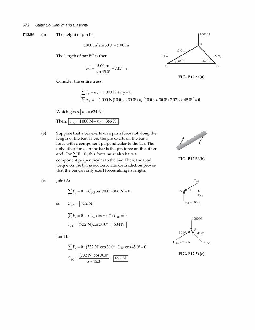
P12.56 (a) The height of pin B is
10 0 30 0 5 00. sin . . m ma f °= .
The length of bar BC is then
BC =°=
5 0045 0
7 07.
sin ..
m m.
Consider the entire truss:
1000 N
B
A C
10.0 mnA nC
30.0° 45.0°
FIG. P12.56(a)
F n n
n
y A C
A C
∑∑
= − + =
= − °+ °+ ° =
1 000 0
1 000 10 0 30 0 10 0 30 0 7 07 45 0 0
N
Nτ b g . cos . . cos . . cos .
Which gives nC = 634 N .
Then, n nA C= − =1 000 366 N N .
(b) Suppose that a bar exerts on a pin a force not along thelength of the bar. Then, the pin exerts on the bar aforce with a component perpendicular to the bar. Theonly other force on the bar is the pin force on the otherend. For F∑ = 0 , this force must also have acomponent perpendicular to the bar. Then, the totaltorque on the bar is not zero. The contradiction provesthat the bar can only exert forces along its length.
FIG. P12.56(b)
(c) Joint A:
Fy =∑ 0 : − °+ =CAB sin .30 0 366 0 N ,
so CAB = 732 N
Fx∑ = 0 : − °+ =C TAB ACcos .30 0 0
TAC = °=732 30 0 634 N Na fcos .
Joint B:
Fx∑ = 0 : 732 30 0 45 0 0 Na fcos . cos .°− °=CBC
CBC =°
°=
732 30 045 0
897 N
Na fcos .
cos .
CAB
ATAC
nA = 366 N
CBC
B
CAB = 732 N
1000 N
30.0° 45.0°
FIG. P12.56(c)
Chapter 12 373
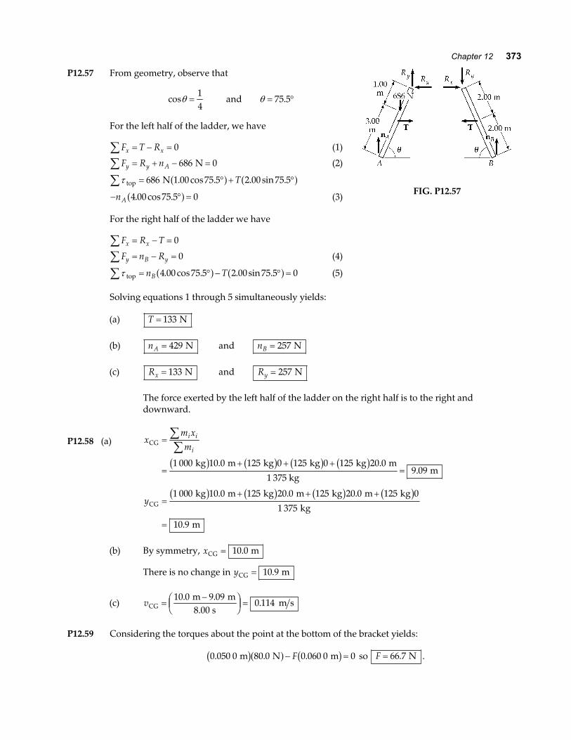
P12.57 From geometry, observe that
cosθ =14
and θ = °75 5.
For the left half of the ladder, we have
F T Rx x∑ = − = 0 (1)
F R ny y A∑ = + − =686 0 N (2)
τ top N∑ = ° + °686 1 00 75 5 2 00 75 5. cos . . sin .a f a fT
− ° =nA 4 00 75 5 0. cos .a f (3)
For the right half of the ladder we have
F R Tx x∑ = − = 0
F n Ry B y∑ = − = 0 (4)
τ top∑ = ° − ° =n TB 4 00 75 5 2 00 75 5 0. cos . . sin .a f a f (5)
FIG. P12.57
Solving equations 1 through 5 simultaneously yields:
(a) T = 133 N
(b) nA = 429 N and nB = 257 N
(c) Rx = 133 N and Ry = 257 N
The force exerted by the left half of the ladder on the right half is to the right anddownward.
P12.58 (a) xm xm
y
i i
iCG
CG
kg m kg kg kg m
1 375 kg m
kg m kg m kg m kg
kg
m
=
=+ + +
=
=+ + +
=
∑∑1 000 10 0 125 0 125 0 125 20 0
9 09
1 000 10 0 125 20 0 125 20 0 125 0
1 375
10 9
b g b g b g b g
b g b g b g b g
. ..
. . .
.
(b) By symmetry, xCG m= 10 0.
There is no change in yCG m= 10 9.
(c) vCG m m8.00 s
m s=−F
HGIKJ =
10 0 9 090 114
. ..
P12.59 Considering the torques about the point at the bottom of the bracket yields:
0 050 0 80 0 0 060 0 0. . . m N mb ga f b g− =F so F = 66 7. N .
374 Static Equilibrium and Elasticity
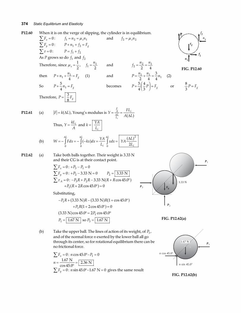
P12.60 When it is on the verge of slipping, the cylinder is in equilibrium.Fx∑ = 0 : f n ns1 2 1= = µ and f ns2 2= µFy∑ = 0 : P n f Fg+ + =1 2
τ∑ = 0: P f f= +1 2
As P grows so do f1 and f2
Therefore, since µ s =12
, fn
11
2= and f
n n2
2 1
2 4= =
FIG. P12.60
then P nn
Fg+ + =11
4(1) and P
n nn= + =1 1
12 434
(2)
So P n Fg+ =54 1 becomes P P Fg+ FHG
IKJ =
54
43
or83
P Fg=
Therefore, P Fg=38
P12.61 (a) F k L= ∆a f, Young’s modulus is YFL
A L
FAL
L
i
i
= =∆ ∆a f
Thus, YkLA
i= and kYALi
=
(b) W Fdx kx dxYAL
xdx YALL
L L
i
L
i= − = − − = =z z z
0 0 0
2
2
∆ ∆ ∆ ∆a f a f
P12.62 (a) Take both balls together. Their weight is 3.33 Nand their CG is at their contact point.
Fx∑ = 0 : + − =P P3 1 0
Fy∑ = 0 : + − =P2 3 33 0. N P2 3 33= . N
τ A∑ = 0: − + − + °P R P R R R3 2 3 33 45 0. cos . Na f+ + ° =P R R1 2 45 0 0cos .a f
Substituting,
− + − + °
+ + ° =
°= °
= =
P R R R
P R
P
P P
1
1
1
1 3
3 33 3 33 1 45 0
1 2 45 0 0
3 33 45 0 2 45 0
1 67 1 67
. . cos .
cos .
. cos . cos .
. .
N N
N
N so N
a f a f a fa f
a f
Fg
P1
P2
P3
3.33 N
FIG. P12.62(a)
(b) Take the upper ball. The lines of action of its weight, of P1 ,and of the normal force n exerted by the lower ball all gothrough its center, so for rotational equilibrium there can beno frictional force.
Fx∑ = 0 : n Pcos .45 0 01°− =
n =°=
1 672 36
.cos
. N
45.0 N
Fy∑ = 0 : n sin . .45 0 1 67 0°− = N gives the same result
1.67 N
n cos 45.0°
n sin 45.0°
P1
FIG. P12.62(b)
Chapter 12 375
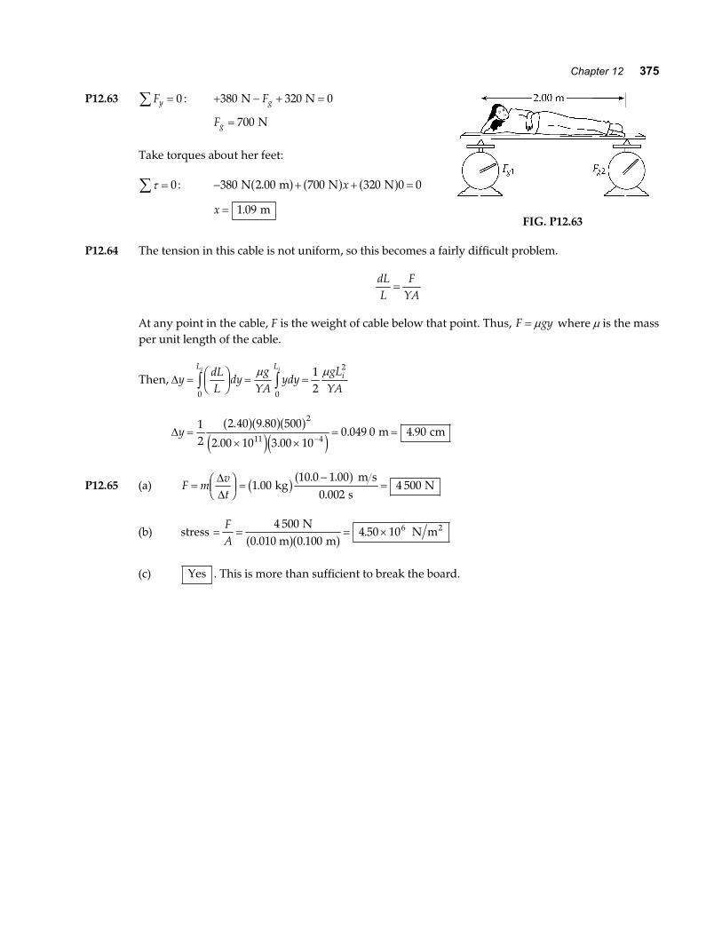
P12.63 Fy∑ = 0 : + − + =380 320 0 N NFg
Fg = 700 N
Take torques about her feet:
τ∑ = 0: − + + =380 2 00 700 320 0 0 N m N N.a f a f a fx
x = 1 09. mFIG. P12.63
P12.64 The tension in this cable is not uniform, so this becomes a fairly difficult problem.
dLL
FYA
=
At any point in the cable, F is the weight of cable below that point. Thus, F gy= µ where µ is the massper unit length of the cable.
Then, ∆ydLL
dyg
YAydy
gLYA
L Li
i i
= FHGIKJ = =z z
0 0
212
µ µ
∆y =× ×
= =−
12
2 40 9 80 500
2 00 10 3 00 100 049 0 4 90
2
11 4
. .
. .. .
a fa fa fe je j
m cm
P12.65 (a) F mvt
= FHGIKJ =
−=
∆∆
1 0010 0 1 00
0 0024 500.
. ..
kg m s
s Nb g a f
(b) stress = = = ×FA
4 5000 100
4 50 106 N0.010 m m
N m2
a fa f..
(c) Yes . This is more than sufficient to break the board.
376 Static Equilibrium and Elasticity
P12.66 The CG lies above the center of the bottom. Consider a disk of water at height y above the bottom.Its radius is
25 0 35 0 25 030 0
25 03
. . ..
. cm cm cm
cm+ − FHG
IKJ = +a f y y
Its area is π 25 03
2
. cm+FHG
IKJ
y. Its volume is π 25 0
3
2
. cm+FHG
IKJ
ydy and its mass is πρ 25 0
3
2
. cm+FHG
IKJ
ydy . The
whole mass of the water is
M dmy y
dy
M yy y
M
M
y
= = + +FHG
IKJ
= + +LNMM
OQPP
= + +LNMM
OQPP
= =
=
−
z z0
30 0 2
0
30 0
2 3
0
30 0
2 3
3
62550 0
3 9
62550 0
6 27
625 30 050 0 30 0
630 0
27
10 27 250 85 6
. .
.
.
.
.. . .
.
cm cm
3 3 kg cm cm kg
πρ
πρ
πρ
π
a f a f a f
e je j
The height of the center of gravity is
yydmM
yy y dy
M
My y y
M
M
y
yCG
cm
cm
cm
34
CG
kg cm cm
kg cm85.6 kg
cm
=
= + +FHG
IKJ
= + +LNMM
OQPP
= + +LNMM
OQPP
=
=× ⋅
=
=
−
zz
0
30 0
2 3
0
30 0
2 3 4
0
30 0
2 3 4
3
3
62550 0
3 9
6252
50 09 36
625 30 02
50 0 30 09
30 036
10453 750
1 43 1016 7
.
.
.
.
.
. . . .
..
πρ
πρ
πρ
π
a f a f a f
e j
Chapter 12 377
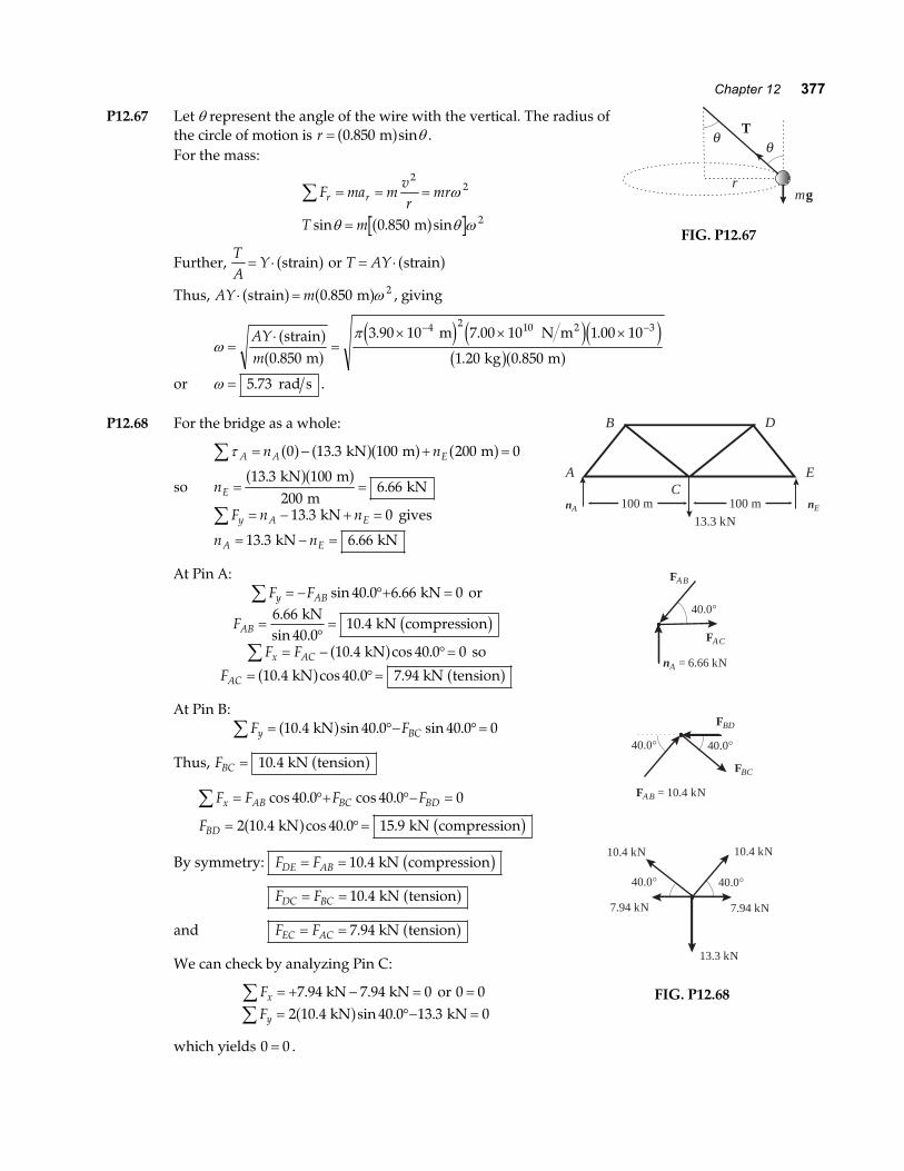
P12.67 Let θ represent the angle of the wire with the vertical. The radius ofthe circle of motion is r = 0 850. sin ma f θ .For the mass:
F ma mvr
mr
T m
r r∑ = = =
=
22
20 850
ω
θ θ ωsin . sin ma fFurther,
TA
Y= ⋅ straina f or T AY= ⋅ straina fThus, AY m⋅ =strain ma f a f0 850 2. ω , giving
θθ
T
rmg
FIG. P12.67
ωπ
=⋅
=× × ×− −
AYm
strain m
m N m
kg m
2a fa f
e j e je jb ga f0 850
3 90 10 7 00 10 1 00 10
1 20 0 850
4 2 10 3
.
. . .
. .
or ω = 5 73. rad s .
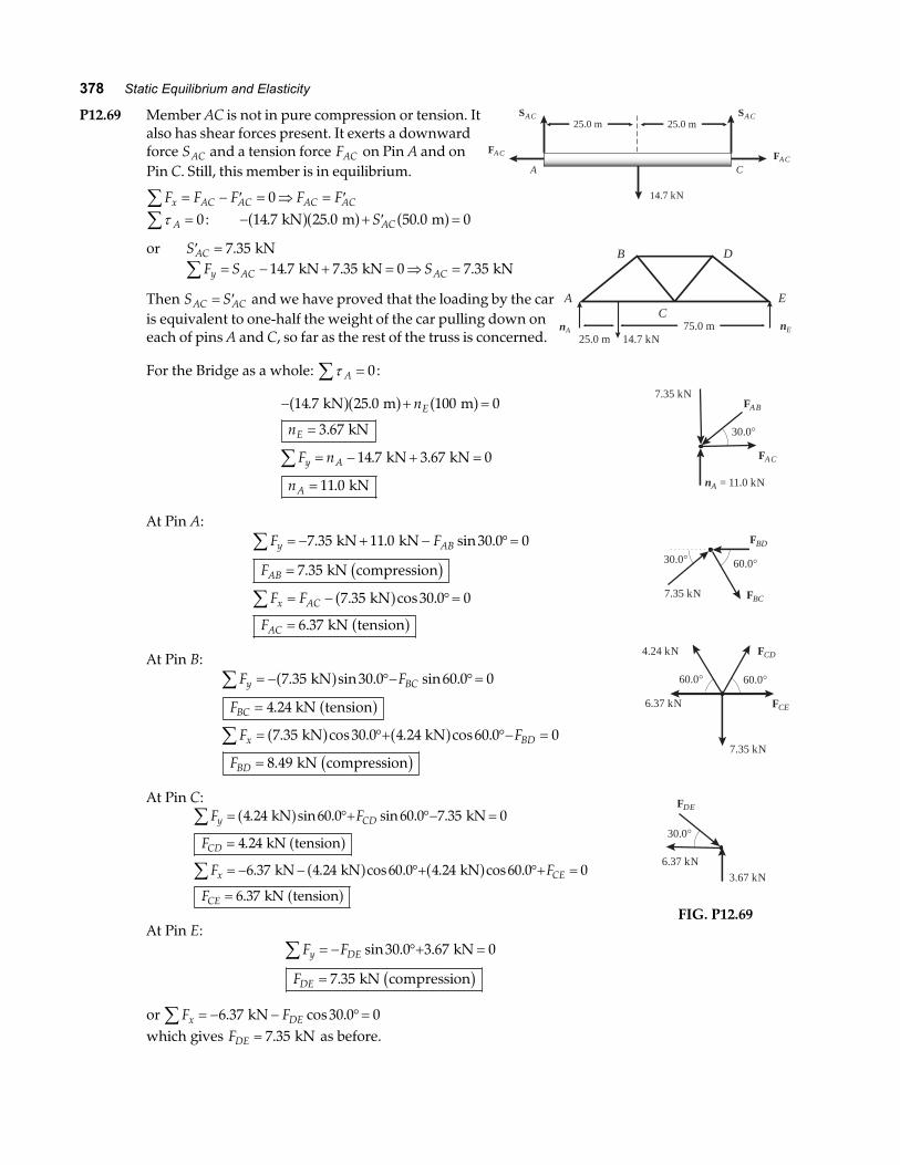
P12.68 For the bridge as a whole:
τ A A En n∑ = − + =0 13 3 100 200 0a f a fa f a f. kN m m
so nE = =13 3 100
2006 66
..
kN m m
kNa fa f
F n ny A E∑ = − + =13 3 0. kN gives
n nA E= − =13 3 6 66. . kN kN
At Pin A:F Fy AB∑ = − °+ =sin . .40 0 6 66 0 kN or
FAB =°=
6 6640 0
10 4.
sin ..
kN kN compressionb g
F Fx AC∑ = − °=10 4 40 0 0. cos . kNa f so
FAC = °=10 4 40 0 7 94. cos . . kN kN tensiona f a fAt Pin B:
F Fy BC∑ = °− °=10 4 40 0 40 0 0. sin . sin . kNa fThus, FBC = 10 4. kN tensiona f
F F F F
F
x AB BC BD
BD
= °+ °− =
= °=
∑ cos . cos .
. cos . .
40 0 40 0 0
2 10 4 40 0 15 9 kN kN compressiona f b gBy symmetry: F FDE AB= = 10 4. kN compressionb g
F FDC BC= = 10 4. kN tensiona fand F FEC AC= = 7 94. kN tensiona fWe can check by analyzing Pin C:
Fx∑ = + − =7 94 7 94 0. . kN kN or 0 0= Fy∑ = °− =2 10 4 40 0 13 3 0. sin . . kN kNa f
which yields 0 0= .
nA nE
A
B
CE
D
100 m 100 m13.3 kN
FAB
FAC
nA = 6.66 kN
40.0°
FBD
FBC
FAB = 10.4 kN
40.0°40.0°
10.4 kN
40.0°40.0°
10.4 kN
7.94 kN 7.94 kN
13.3 kN
FIG. P12.68
378 Static Equilibrium and Elasticity
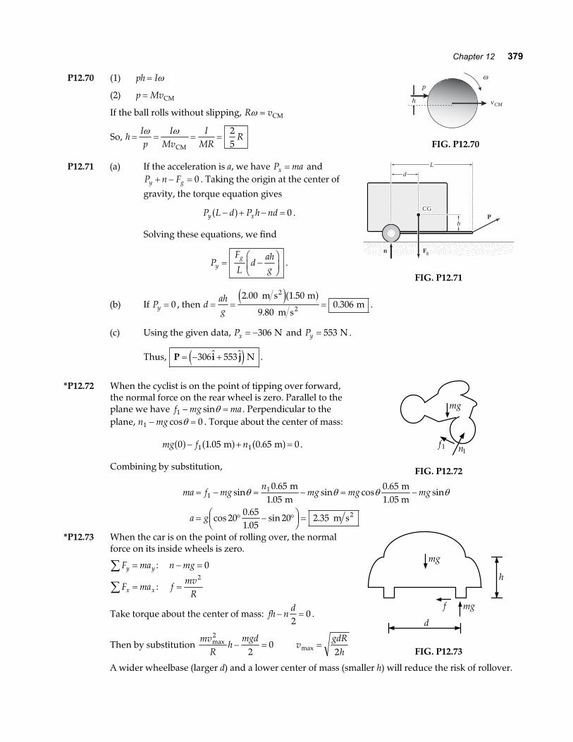
P12.69 Member AC is not in pure compression or tension. Italso has shear forces present. It exerts a downwardforce SAC and a tension force FAC on Pin A and onPin C. Still, this member is in equilibrium.
F F F F Fx AC AC AC AC∑ = − ′ = ⇒ = ′0
25.0 m
A
25.0 m
14.7 kN
C
FAC FAC
SAC SAC
τ A =∑ 0: − + ′ =14 7 25 0 50 0 0. . . kN m ma fa f a fSAC
or ′ =SAC 7 35. kNF S Sy AC AC∑ = − + = ⇒ =14 7 7 35 0 7 35. . . kN kN kN
Then S SAC AC= ′ and we have proved that the loading by the caris equivalent to one-half the weight of the car pulling down oneach of pins A and C, so far as the rest of the truss is concerned.
nA nE
A
B
CE
D
25.0 m 14.7 kN75.0 m
For the Bridge as a whole: τ A∑ = 0:
− + =
=
= − + =
=
∑
14 7 25 0 100 0
3 67
14 7 3 67 0
11 0
. .
.
. .
.
kN m m
kN
kN kN
kN
a fa f a fn
n
F n
n
E
E
y A
A
At Pin A:F F
F
F F
F
y AB
AB
x AC
AC
∑
∑
= − + − °=
=
= − °=
=
7 35 11 0 30 0 0
7 35
7 35 30 0 0
6 37
. . sin .
.
. cos .
.
kN kN
kN compression
kN
kN tension
b ga fa f
At Pin B:F F
F
F F
F
y BC
BC
x BD
BD
∑
∑
= − °− °=
=
= °+ °− =
=
7 35 30 0 60 0 0
4 24
7 35 30 0 4 24 60 0 0
8 49
. sin . sin .
.
. cos . . cos .
.
kN
kN tension
kN kN
kN compression
a fa f
a f a fb g
At Pin C:F F
F
F F
F
y CD
CD
x CE
CE
∑
∑
= °+ °− =
=
= − − °+ °+ =
=
4 24 60 0 60 0 7 35 0
4 24
6 37 4 24 60 0 4 24 60 0 0
6 37
. sin . sin . .
.
. . cos . . cos .
.
kN kN
kN tension
kN kN kN
kN tension
a fa fa f a fa f
At Pin E:F F
F
y DE
DE
∑ = − °+ =
=
sin . .
.
30 0 3 67 0
7 35
kN
kN compressionb gor F Fx DE∑ = − − °=6 37 30 0 0. cos . kNwhich gives FDE = 7 35. kN as before.
FAB
FAC
nA = 11.0 kN
30.0°
7.35 kN
FBD
FBC7.35 kN
60.0°30.0°
4.24 kN
60.0°60.0°
6.37 kN
7.35 kN
FCD
FCE
FDE
6.37 kN
30.0°
3.67 kN
FIG. P12.69
Chapter 12 379
P12.70 (1) ph I= ω
(2) p Mv= CM
If the ball rolls without slipping, R vω = CM
So, hIp
IMv
IMR
R= = = =ω ω
CM
25
ωp
h vCM
FIG. P12.70
P12.71 (a) If the acceleration is a, we have P max = andP n Fy g+ − = 0 . Taking the origin at the center of
gravity, the torque equation gives
P L d P h ndy x− + − =a f 0 .
Solving these equations, we find
PF
Ld
ahgy
g= −FHGIKJ .
hhP
CGCGCG
ddHL
Fyn Fgn
FIG. P12.71
(b) If Py = 0 , then dahg
= = =2 00 1 50
9 800 306
. .
..
m s m
m s m
2
2
e ja f.
(c) Using the given data, Px = −306 N and Py = 553 N .
Thus, P i j= − +306 553e j N .
*P12.72 When the cyclist is on the point of tipping over forward,the normal force on the rear wheel is zero. Parallel to theplane we have f mg ma1 − =sinθ . Perpendicular to theplane, n mg1 0− =cosθ . Torque about the center of mass:
mg f n0 1 05 0 65 01 1a f a f a f− + =. . m m .
Combining by substitution,
mg
n1f1
FIG. P12.72
ma f mgn
mg mg mg
a g
= − = − = −
= ° − °FHG
IKJ =
11 0 651 05
0 65
200 651 05
20 2 35
sin.
.sin cos
.sin
cos..
sin .
θ θ θ θ m
m m
1.05 m
m s2
*P12.73 When the car is on the point of rolling over, the normalforce on its inside wheels is zero.
F may y∑ = : n mg− = 0
F max x∑ = : fmv
R=
2
Take torque about the center of mass: fh nd
− =2
0 .
Then by substitution mv
Rh
mgdmax2
20− = v
gdRhmax = 2
mg
h
mgf
d
FIG. P12.73
A wider wheelbase (larger d) and a lower center of mass (smaller h) will reduce the risk of rollover.
380 Static Equilibrium and Elasticity
ANSWERS TO EVEN PROBLEMS
P12.2 F R Fy y g+ − = 0 ; F Rx x− = 0 ; P12.40 (a) 0.400 mm; (b) 40.0 kN; (c) 2.00 mm;(d) 2.40 mm; (e) 48.0 kN
F F Fy g xcos cos sinθ θ θ− FHGIKJ − =
20
P12.42 at A: Mgsin
sinβ
α β+b g ; at B: Mgsin
sinα
α β+b gP12.4 see the solution
P12.44 (a) 160 N to the right;P12.6 0.750 m(b) 13.2 N to the right; (c) 292 N up;
P12.8 2 54 4 75. . m, ma f (d) 192 N
P12.46 1 46. kN; 1 33 2 58. .i j+e j kNP12.10 (a) 9.00 g; (b) 52.5 g; (c) 49.0 g
P12.12 (a) 392 N; (b) 339 0i j+e j N P12.48 0.789
P12.14 (a) fm g m gx
L= +LNM
OQP
1 2
2cotθ ;
n m m gg = +1 2b g ; (b) µθ
=+
+
m m dL
m m
1 22
1 2
e jcot
P12.50 T = 1 68. kN; R = 2 34. kN; θ = °21 2.
P12.52 (a) see the solution; (b) 60.0°
P12.54 (a) 120 N; (b) 0.300; (c) 103 N at 31.0° abovethe horizontal to the right
P12.16 see the solution; 0.643 mP12.56 (a), (b) see the solution;
P12.18 36 7. N to the left ; 31 2. N to the right (c) CAB = 732 N ; TAC = 634 N ; CBC = 897 N
P12.20 (a) 35.5 kN; (b) 11.5 kN to the right; P12.58 (a) 9 09 10 9. . m, ma f ; (b) 10 0 10 9. . m, ma f ;(c) 4.19 kN down (c) 0 114. m s to the right
P12.22 (a) 859 N; (b) 104 kN at 36.9° above thehorizontal to the left P12.60
38
Fg
P12.2434L
P12.62 (a) P1 1 67= . N ; P2 3 33= . N ; P3 1 67= . N;(b) 2.36 N
P12.26 (a) see the solution; (b) θ decreases ;P12.64 4.90 cm(c) R decreases
P12.66 16.7 cm above the center of the bottomP12.28 (a) 73.6 kN; (b) 2.50 mm
P12.30 ~1 cm P12.68 CAB = 10 4. kN ; TAC = 7 94. kN ;TBC = 10 4. kN ; CBD = 15 9. kN ;CDE = 10 4. kN ; TDC = 10 4. kN ;TEC = 7 94. kN
P12.32 9 85 10 5. × −
P12.34 0 029 3. mm
P12.7025
RP12.36 (a) −0 053 8. m3 ; (b) 1 09 103. × kg m3 ;(c) Yes, in most practical circumstances
P12.72 2 35. m s2
P12.38 (a) 53.1°; (b) 1.04 kN; (c) 0.126 m, 51.2°;(d) 1.07 kN; (e) 0.129 m, 51.1°; (f) 51.1°


![Chapter 12 Static Equilibrium and Elasticityfisica.upct.es/tasio/edificacion/PRO_RESU/Cap12.pdf · 1197 Chapter 12 Static Equilibrium and Elasticity Conceptual Problems 1 • [SSM]](https://img.pdfslide.net/doc/110x75/5a9dfab47f8b9ad2298ba39f/chapter-12-static-equilibrium-and-chapter-12-static-equilibrium-and-elasticity-conceptual.jpg)
![Chapter 12 Static Equilibrium and Elasticity...1185 Chapter 12 Static Equilibrium and Elasticity Conceptual Problems 1 • [SSM] True or false: (a) G F ii ∑ =0 is sufficient for](https://img.pdfslide.net/doc/110x75/60cb9597eeb3a275f25b50f1/chapter-12-static-equilibrium-and-elasticity-1185-chapter-12-static-equilibrium.jpg)