Embed Size (px)
Citation preview
GEK-36372A
STATIC EXCITER-REGULATOR
EQUIPMENT WITH
3 OR 4 RECTIFIER BRIDGES
3S7931EA--- SERIES
3S?931EA--- Series Static Exciter-Regulator Equipment GEK-36372
INTRODUCTION .............................................................
RECEIVING, HANDLING AND STORAGE ....................................... Receiving and Handling Storage
................................................... .................................................................
DESCRIPTION .............................................................. Component Arrangement .................................................. Static Magnetic Power Components and Power Rectifiers ..................... Silicon Diode Fundamentals ............................................... Automatic Voltage Regulator .............................................. Manual Regulator ......................................................... Auxiliary Equipment ...................................................... Control Equipment ....................................................... P.T. and C.T. Burdens ..................................................
INSTALLATION .............................................................. Location and Mounting ’
’ Connections ...................................................
............................................................. Polarity and Phase Rotation .......................................... ...>.
INITIAL OPERATION, TEST, AND ADJUSTMENT ............................... Control Circuits .......................................... Static Exciter
, .............. ...........................................................
Initial Operation ......................................................... Underexcited Reactive-Ampere Limit ...................................... Reactive-Current Compensator ............................................ Active -and-Reactive Current Compensator . . . . . . . . . . . . . . . . . . . . . . . . . . . . . . . . . .
Gain Measurements ......................................................
System Self -Compensation ................................................
OPERATION ................................................................ Normal Operation .......................................................
MAINTENANCE ............................................................. PPT’s And SCT’s ....................................................... Static Equipment ......................................................... Other Equipment .........................................................
RENEWAL PARTS ...........................................................
TROUBLESHOOTING .........................................................
PAGE
3
3 3 4
7"
i
:i
12
:i 12
12
:i 14 15 18 18 18
18
18 18
19 19 19 19
20
21
These instructions do not purport to cover all details or variations in equipment nor to provide for every possible contingency to be met in connection with installation, operation or maintenance. Should further information be desired or should particular problems arise which are not covered sufficiently for the purchaser’s purposes, the matter should be referred to General Electric Company.
3S7931EL-,SERIES STATIC EXClTER-REGULATOR EQUIPMENT
lNfRODlJCTlON The 3S7931EA ___ silicon controlled rectifier @CR) Static Exciter Regulator equipment performs its re- gulation and excitation function by monitoring generator line voltage and current and producing the proper excitation conditions required by the machine.
The power potential transformers (PPT’s) and satu- rable current transformers (SCT’s) are the main source of power for the generator field; at no load all field power is obtained from the PPT’s and from the SCT’s at full load. The power from these two units is recti- fied by the three-phase silicon diode rectifiers and then applied to the field of the generator.
The primaries of the SCT being in the neutral leads of the machine provide some inherent self regulation. Theorectically, this self regulation should completely compensate for load changes, however, generator saturation, field heating, and other secondary effects make it necessary to add more compensation. This extra compensation is obtained by saturating the SCT with a d-c control winding current. The amount of d-c required is obtained from the automatic regulator whose input continuously monitors line current and voltage when in the automatic mode of operation. Also, a manual control of the d-c control winding current is provided.
The automatic regulator may be equipped with an underexcited reactive - ampere limit circuit, which prevents the excitation of the machine from being reduced to a point below a desired minimum value. The regulator and underexcited reactive - ampere limit components are located on separate panels.
A reactive current compensator is always included to permit proper division of reactive current and to restrict the flow of circulating currents between paralleled machines. In the case of single machines, its connections may be reversed to reduce the ef- fective impedance of the line transformers. An ’ active-and-reactive-current compensator is occa- sionally provided to facilitate the regulation of voltage at some point remote from the machine terminals. Combinations of the above two compensators can be furnished which will accomplish both functions simul- taneously. The excitation equipment also includes a start-up circuit for field flashing, rheostat for manual control, the machine field breaker, and the necessary control transformers, switches, relays, and other components to assure proper operation.
Other components, such as an a-c machine field breaker for a spare exciter, are sometimes furnished. Both the number and the arrangement of auxiliary components vary with the requirements of the partic- ular application. Therefore, It is necessary to re- fer to the material lists and diagrams provided for each individual application to determine what material is included and what connections should be used. The diagrams shown in this book are for illustrative pur-
poses only; they are not intended to apply to all in- stallations.
RECEIWNG, HANDLtNG AND STORAGE
RECEIVING AND HANDLING
Immediately upon receipt, the equipment should be carefully unpacked to avoid damaging the apparatus. Particular care should be exercised to prevent small parts being mislaid or thrown away in the packing material.
As soon as the equipment is unpacked it should be examined for any damage that might have been SUS- tained in transit. If injury or rough handling is evident, a damage claim shall be filed immediately with the transportation company and the nearest General Electric Sales Office should be notified promptly.
STORAGE
If the equipment is not to be used as soon as it is un- packed, it should be stored in a clean dry place snd protected from accidental damage. Particular care should be exercised to avoid stormg the equipment in locations where construction work is in progress.
DESCRIPTION
COMPONENT ARRANGEMENT
The 3S7931EA--- static -exciter -regulator consists of a main cubicle plus the following separately- mounted equipments:
1. Three power potential transformers, which are floor mounted. They are sometimes mounted in a single case. These step-down transformers supply power for the field and the regulator.
2. Three saturable current transformers, which may be suspended from the bottom of the machine, or be floor-mounted.
3. Regulator control switch, field breaker control switch, transfer volt meter, manual regulator contra switch, and exciter voltmeter which are mounted on the control board.
The main cubicle is a floor-mounted enclosure that can be opened at both the front and the back. It usually includes the following units:
1. A 3S793ONA 157 . . . . . . . . Comparison and Trigger Circuit Panel
2. A 3S7932IL4.. . . . . . . . . . . . Underexcited re- active ampere limit panel and limit amplifier panel. 3
3S7931EA--- Series Static Exciter-Regulator Equipment GEK-36372
3.
4.
5.
6.
7.
8.
9.
10.
A 3S7932CD.. . . . . . . . . . . . . . DC Control Panel which contains transfer contactor 9, protective relays, fuses, and other control devices.
A 3S7930NA158 . . . ...*.... Manual Regulator Panel
At Least two air-cooled three-phase full-wave bridge rectifiers with high temperature switches.
Three linear reactors.
One linear field-discharge resistor.
Main exciter field breaker.
Thyrite* resistors for rectifier protection.
Miscellaneous shunts and fuses.
All of the above panels have steel bases except for specially constructed bases for the disconnect switches and field breakers.
STATIC MAGNETlC POWER COMPONENTS AND POWER RECTIFIERS
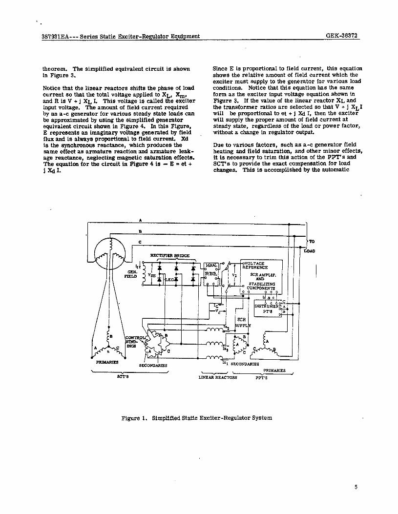
The power potential transformers (PPT’s) have their primary windings wye-connected to the generator terminals. The secondaries of the power potential transformers are connected to the power rectifier section through linear reactors as illustrated in Fig- ure 1. Each saturable current transformer (SCT) primary is located in a line of the generator on the neutral side. The secondary of each saturable cur- rent transformer is connected from line to line of the bridge rectifier. When the generator is operating at no-load, the power potential transformers supply voltage to the three-phase full-wave bridge rectifiers so that a uni -directional voltage, VSE, is applied to the field of the generator. Field voltage is controlled by means of the saturable current transformers. The exciting current of the saturable current transformers is virtually proportional to the d-c current, Ic, flowing in their control windings. This exciting current flows from the PPT secondaries through the linear reactors into the SCT secondaries. When I, is increased, the increased exciting current causes increased voltage
*Registered Trademark of General Electric Co. 4
drop across the linear reactors so that the input voltage to the bridge rectifier and, consequently, the field voltage is decreased. Thus, no-load terminal voltage of the generator is controlled by the value of
The control windings of the SCT’s are connected in series. A resistor is connected across each control winding to reduce the magnitude of the a-c voltage appearing across the control winding.
When the machine is supplying current to a load, the SCT primaries carry the load current. This primary current helps the secondary current excite the iron core. Therefore, an increase in primary current causes a decrease in secondary exciting current for a given value of Ic. A decrease in secondary exciting current decreases the voltsige drop across the linear reactors with the result that bridge rectifier input voltage and field voltage are increased. The turns ratios of the SCT’s and the PPT’s and the reactance of the linear reactors are selected so that this in- crease in field voltage which accompanies an increase in load current is approximately the increase neces- sary to hold terminal voltage constant.
It is an object of the design to maintain required ter- minal voltage on the machine without requiring a change in control current Ic.
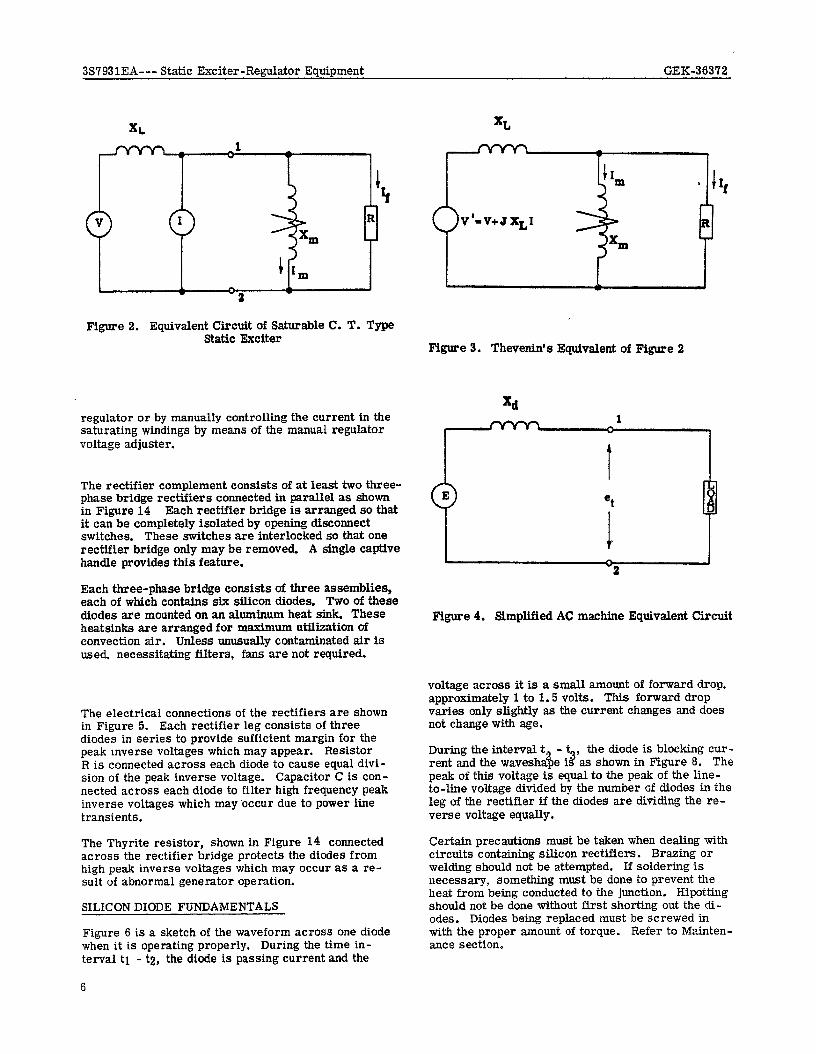
Operation of the static magnetic power components can be better understood by referring to the equivalent circuit illustrated in Figure 2 where:
v- -
XL - I -
R -
If -
Irn -
xm -
generator terminal voltage (referred to PPT secondary).
reactance of the linear reactor.
Load current (referred to SCT secondary).
resistance of the generator field (referred to the a-c side of the rectifier).
field current (on the a-c side of the recti- fier).
is the magnetizing current of the saturable current transformer (referred to SCT secondary).
magnetizing reactance of the SCT (referred to the secondary). This reactance decreases with an increase in direct current from the regulator.
From this equivalent circuit the field current at no load is obtained from the generator terminal voltage
X shunts current away from the gen- %~~hfi%, Rtmthus providing control. Under load, the load current, I adds additional current, part of which goes through the generator field R. This equivalent circuit can be simplified by replacing the circuit to the left of point 1 - 2 with an equivalent voltage source and series impedance using ThevenuYs
3S’t931EA--- Series Static Exciter-Regulator Equipment GEK-36372
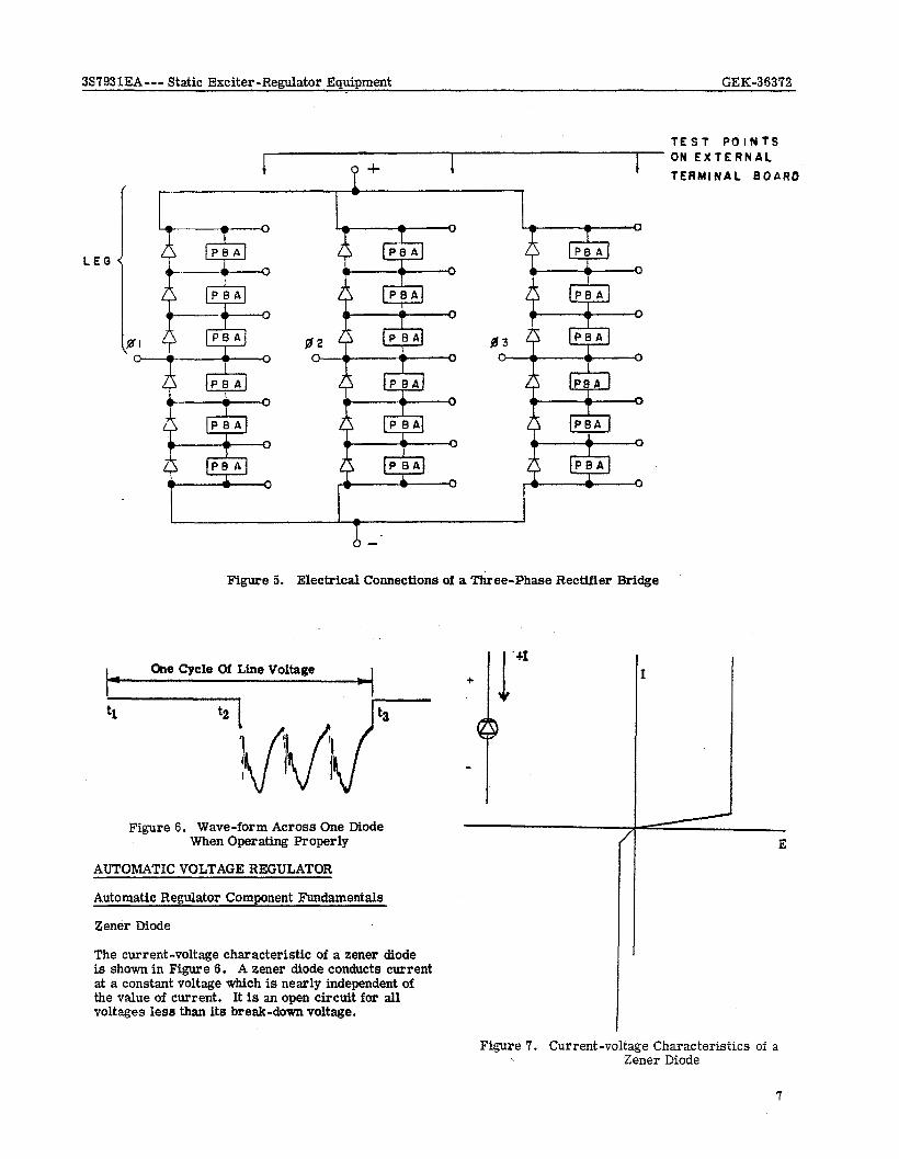
theorem. The simplified equivalent circuit is shown in Figure 3.
Notice that the linear reactors shifts the phase of load current so that the total voltage applied to XL, X,, and It is V + j XL I. This voltage is called the exciter input voltage. The amount of field current required by an a-c generator for various steady state loads can be approximated by using the simplified generator equivalent circuit shown ln Figure 4. In this Figure, E represents an imaginary voltage generated by field . flux and is always proportional to field current. Xd is the synchronous reactance, which produces the same effect as armature reaction and armature leak- age reactance, neglecting magnetic saturation effects. The equation for the circuit in Figure 4 is - E = et + I XdI.
Since E is proportional to field current, this equation shows the relative amount of field current which the exciter must supply to the generator for various load conditions. Notice that this equation has the same form as the exciter input voltage equation shown in Figure 3, If the value of the linear reactor XL and the transformer ratios are selected so that V + j Xl,1 will be proportional to et + j Xd I, then the exciter will supply the proper amount of field current at steady state, regardless of the load or power factor, without a change in regulator output.
Due to various factors, such as a-c generator field heating and field saturation, and other minor effects, it is necessary to trim this action of the PPT’s and SCT’s to provide the exact compensation for load changes. This is accomplished by the automatic
B
c
usn* < v' ?mr-
L "- *
I SCRAMPLIF.
,I
\ c PRIMARIES SCTS LINEAR REhCl-ORS PPT'S
Figure 1. Simplified Static Exciter-Regulator System
3S7931EA--- Static Exciter-Regulator Equipment GEK-36372
Figure 2. Equivalent Circuit of Saturable C. T. Type Static Exciter
regulator or by manually controlling the current in the saturating windings by means of the manual regulator voltage adjuster.
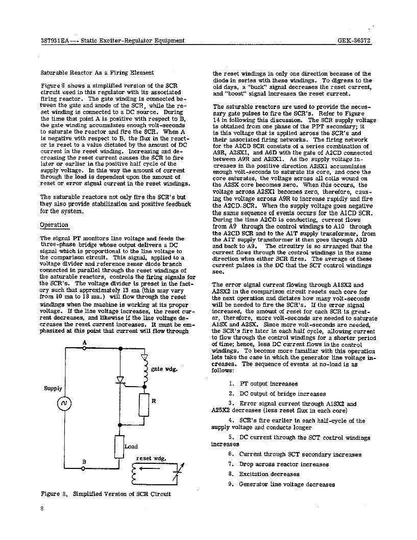
The rectifier complement consists of at least two three- phase bridge rectifiers connected in parallel as shown in Figure 14 Each rectifier bridge is arranged so that it can be completely isolated by opening disconnect switches. These switches are interlocked so that one rectifier bridge only may be removed. A single captive handle provides this feature.
Each three-phase bridge consists of three assemblies, each of which contains six silicon diodes. Two of these diodes are mounted on an aIuminum heat sink. These heatsinks are arranged for maximum utilization of convection air. Unless unusua.Iiy contaminated air is used. necessitating filters, fans are not required.
The electrical connections of the rectifiers are shown in Figure 5. Each rectifier leg consists of three diodes in series to provide sufficient margin for the peak inverse voltages which may appear. Resistor R is connected across each diode to cause equal divi- sion of the peak inverse voltage. Capacitor C is con- nected across each diode to filter high frequency peak inverse voltages which may ‘occur due to power line transients.
The Thyrite resistor, shown in Figure I4 connected across the rectifier bridge protects the diodes from high peak inverse voltages which may occur as a re- sult of abnormal generator operation.
SILICON DIODE FUNDAMENTALS
Figure 6 is a sketch of the waveform across one diode when it is operating properly. During the time in- terval tI - t2, the diode is passing current and the
Figure 3. Thevenin’s Equivalent of Figure 2
1
t
et
i
Figure 4. Simplified AC machine Equivalent Circuit
voltage across it is a small amount of forward drop. approximately 1 to 1.5 volts. This forward drop varies only slightly as the current changes and does not change with age.
- t During the interval t$ .d , the diode is blocking cur- rent and the wavesha e 1 as shown in Figure 8. The peak of this voltage is equal to the peak of the Iine- to-line voltage divided by the number of diodes in the leg of the rectifier if the diodes are dividing the re- verse voltage equally.
Certain precautions must be taken when dealing with circuits containing silicon rectifiers. Brazing or welding should not be attempted. If soldering is necessary, something must be done to prevent the heat from being conducted to the junction. Hipotting should not be done without first shorting out the dl- odes. Diodes being replaced must be screwed in with the proper amount of torque. Refer to Mainten- ance section.
6
3S7931EA --- Static Exciter-Regulator Equipment GEK-36372
TEST POINTS ON EXTERNAL
TERMINAL BOAR0
LEG
Figure 5. Electrical Connections of a Three-Phase Rectifier Bridge
One Cycie Of Line Voltage I
Figure 6. Wave-form Across One Diode When Operating Properly
AUTOMATIC VOLTAGE REGULATOR
Automatic Regulator Component Fundamentals
Zener Diode
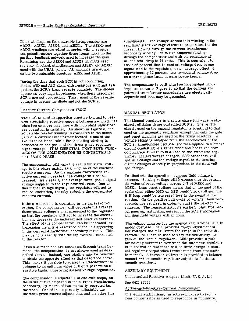
The current-voltage characteristic of a zener diode is shown in Figure 6. A zener diode conducts current at a constant voltage which is nearly independent of the value of current. It is au open circuit for all voltages less than its break-down voltage.
I
Figure 7. Current-voltage Characteristics of a Zener Diode
7
3S7931EA--- Static Exciter-Regulator Equipment GEK-36372
Saturable Reactor As a Firing Element
Figure 8 shows a simplified version of the SCR circuit used in this regulator with its associated firing reactor. The gate winding is connected be- tween the gate and anode of the SCR, while the re- set winding is connected to a DC source. During the time that point A is positive with respect to B, the gate winding accumulates enough volt -seconds to saturate the reactor and fire the SCR. When A is negative with respect to B, the flux in the react- or is reset to a value dictated by the amount of DC current in the reset winding. Increasing and de- creasing the reset current causes the SCR to fire later or earlier in the positive half cycle of the supply ‘voltage. In this way the amount of current through the load is dependent upon the amount of reset or error signal current in the reset windings.
The saturable reactors not only fire the SCR’s but they also provide stabilization and positive feedback for the system.
Operation
The signal PT monitors line voltage and feeds the three-phase bridge whose output delivers a DC signal which is proportional to the Iine voltage to the comparison circuit. This signal, applied to a voltage divider and reference zener diode branch connected in parallel through the reset windings of the saturable reactors, controls the firing signals for the SCR’s. The voltage divider is preset in the fact- ory such that approximately 13 ma (this may vary from 10 ma to 18 ma.) will flow through the reset windings when the machine is working at its proper voltage. ILf the line voltage increases, the reset cur- rent decreases, and likewise if the line voltage de- creases the reset current increases. It must be em- phasized at this point that current will flow through
A
gate wdg.
SUPPlY
Load
,” fB
Figure 8. Simplified Version of SCR Circuit
8
the reset windings in only one direction because of the diode in series with these windings. To digress to the old days, a “buck” signal decreases the reset current, and “boost” signal increases the reset current.
The saturable reactors are used to provide the neces- sary gate pulses to fire the SCR’s. Refer to Figure 14 in following this discussion. The SCR supply voltage is obtained from one phase of the PPT secondary; it is this voltage that is applied across the SCR’s and their associated firing networks. The firing network for the ASCD SCR consists of a series combination of A9R, A2SK1, and A6D with the gate of AZCD connected between A9R and A2SXl. As the supply voltage in- creases in the positive direction A2SX1 accumulates enough volt-seconds to saturate its core, and once the core saturates, the voltage across all coils wound on the A2SK core becomes zero. When this occurs, the voltage across A2SXl becomes zero, therefore, caus- ing the voltage across A9R to increase rapidly and fire the A2CD. SCR. When the supply voltage goes negative the same sequence of events occurs for the AlCD SCR. During the time A2CD is conducting, current flows from A9 through the control windings to A10 through the ABCD SCR and to the AlT supply transformer, from the AIT supply transformer it then goes through A3D and back to A9. The circuitry is so arranged that the current flows through the control windings in the same direction when either SCR fires. The average of these current pulses is the DC that the SCT control windings see.
The error signal current flowing through AlSX2 and A2SK2 in the comparison circuit resets each core for the next operation and dictates how many volt-seconds will be needed to fire the SCR’s. If the error signal increases, the amount of reset for each SCR is great- er, therefore, more volt-seconds are needed to saturate AlSK and AZ%. Since more volt-seconds are needed, the SCR’s fire later in each half cycle, allowing current to flow through the control windings for a shorter period of time; hence, less DC current flows inthe control windings. To become more familiar with this operation lets take the case in which the generator line voltage in- creases. The sequence of events at no-load is as follows:
1. PT output increases 2. DC output of bridge increases 3. Error signal current through AlSK2 and
A25X2 decreases (less reset flux in each core) 4. SCR’s fire earlier in each half-cycle of the
supply voltage and conducts longer 5. DC current through the SCT control windings
increases 6. Current through SCT secondary increases 7. Drop across reactor increases 8. Excitation decreases
9. Generator line voltage decreases
3S7931EA--- Static Exciter-Regulator Equipment GEX-36372
Other windings on the saturable firing reactor are AlSX3. A2SX3, AlSX4, and A2SX4. The AlSXS and A2SX3 windings are wired in series with a reactor and potentiometer: together these items make up the positive feedback network used to increase the gain. Remaining are the AlSX4 and A2SX4 windings used for rate feedback stabilization and AlSXS and A2SX5 used with the URAL panel. All windings are wound on the two saturable reactors AlSX and A2SX.
During the time that each SCR is not conducting, diodes A5D and AZD along with resistors A8R and A7R protect the SCR’s from reverse voltages. The diodes appear as very high impedances when their associated SCR’s are not conducting. Thns, most of the reverse voltage is across the diode and not the SCR’s.
Reactive Current Compensator (RCC)
The RCC is used to apportion reactive kva and to pre- vent circulating reactive current between a-c machines when two or more machines with individual regulators are operating in parallel. As shown in Figure 8, the adjustable reactor winding is connected to the secon- dary of a current transformer located in one of the a-c machine lines, while the insulating winding is connected on one phase of the three-phase regulator signal voltage. IT IS ESSENTIAL THAT BOTH WIND- INGS OF THE COMPENSATOR BE CONNECTED IN THE SAME PHASE.
The compensator will vary the regulator signal volt- age in this phase mainly as a function of the machine reactive current. As the machme overexcited re- active current increases, the voltage will be in- creased. As a result, the average three-phase signal voltage supplied to the regulator will rise. Due to this higher voltage signal, the regulator will act to reduce excitation, thereby reducing the overexcited reactive current.
If the a-c machine is operating in the underexcited region, the compensator will decrease the average three-phase voltage signal presented to the regulator so that the regulator will act to increase the excita- tion and decrease the underexcited reactive current. The effect of the compensator can be increased by increasing the active reactance of the unit appearing in the current-transformer secondary circuit. This may be done readily with the ta.p switches connected to the reactor.
If two a-c machines are connected through transfor- mers, the compensator is not always used as des- cribed above. Instead, one winding may be reversed to obtain the opposite effect as that described above. This makes it possible to adjust the transformer im- pedance to an optimum value of 6 or 7 percent on a reactive basis, improving system voltage regulation.
The compensator is adjustable in one-volt steps, on the basis of five amperes in the current-transformer secondary, by means of two manually-operated tap switches. One of the separately-adjustable tap switches gives coarse adjustments and the other fine
adjustments, The voltage across this winding in the regulator signal-voltage circuit is proportional to the current flowmg through the current transformer secondary winding. With five amperes flowing through the compensator and with the reactance all in, the total drop is 24 volts. This is equivalent to about 36 percent line-to-neutral voltage drop in one signal lead to the regulator, or an average effect of approximately 12 percent line-to-neutral voltage drop on a three-phase basm at zero power factor.
The compensator is built with two independent wind- ings, as shown in Figure 6, so that the current and potential transformer secondaries are electrically separate and both may be grounded.
MANUAL REGULATOR
The Manual regulator is a single phase full wave bridge circuit utilizing phase controlled SCR’s. The bridge circuit used on the manual regulator is identical to that used on the automatic regulator except that only the gate and reset windings are used on the firing reactors. A voltage signal is obtained from the secondaries of the SCT’s, transformed rectified and then applied to a bridge circuit consisting of a zener diode and linear resistor combination similar to that used on the automatic reg- ulator. If field voltage changes. SCT secondary volt- age will change and the voltage signal to the sensing circuit changes directly in proportion to the field volt- age change.
To illustrate the operation. suppose field voltage in- creases. Sensing voltage will increase thus decreasing the value of reset voltage across 6-7 of MlSX and M2SX. Less reset voltage means that on the part of the cycle when either M6D or MlD would block voltage. the B-H loop would be traversed less in the negative di- rection. On the positive half cycle of voltage. less vl,lt- seconds are required in order to cause the reactor to saturate. The reactors saturate earlier, regulator out- put goes up, saturating current in the SCT’s mcreases and thus field voltage will go down.
The voltage adluster for the manual regulator is usually motor operated. MlP provides range adjustment at low voltages and M2P limits the range in the raise di- rection. M3P can be used to vary the sensitivity i;r gain of the manual regulator. M9R provides a path for holding current to flow when the automatic reg&tl:r is in control so that there will be little change in man- ual regulator output when transferring from automatic to manual. A transfer voltmeter is provided to balance manual and automatic regulator outputs to facihtate smooth transfers.
AUXILIARY EQUIPMENT Underexcited Reactive-Ampere Limit (U. R. A. L.) See GEI-98155 Active-and-Reactive-Current Compensator In special applications. an active-and-reacdve-cur- rent compensator is used to reproduce in miniature.
3S7931EA--Static Exciter-Regulator Equipment GEK-36312
A-C MACHINE
POTENTIAL TWNSFORMERE
v LOAD
NOTE: DROOPCONNECTION Is snoww.
TOREFERENCEAND COMPAIWONClRCUIT
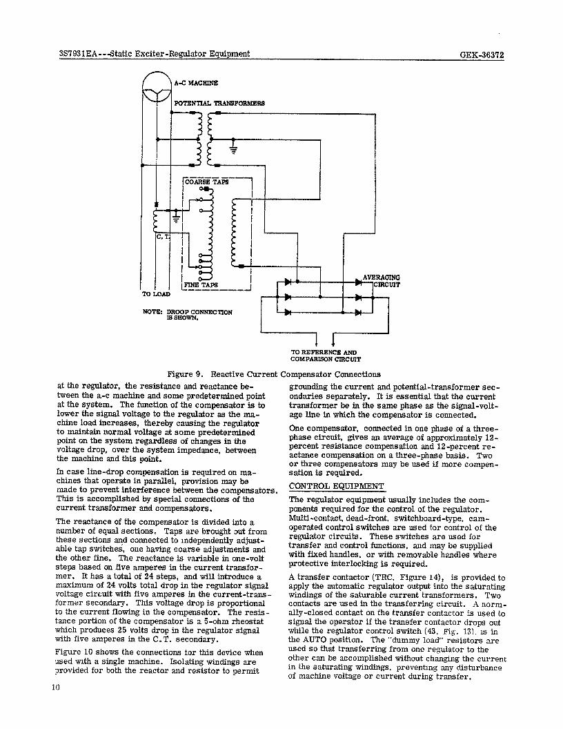
Figure 9. Reactive Current Compensator Connections at the regulator, the resistance and reactance be- tween the a-c machine and some predetermined point at the system. The function of the compensator is to lower the signal voltage to the regulator as the ma- chine load increases, thereby causing the regulator to maintain normal voltage at some predetermined point on the system regardless of changes in the voltage drop, over the system impedance, between the machine end this point. In case line-drop compensation is required on ma- chines that operate in parallel, provision may be made to prevent interference between the compensators. This is accomplished by special connections of the current transformer and compensators.
The reactance of the compensator is divided into a number of equal sections. Taps are brought out from these sections and connected to mdependently adjust- able tap switches, one having coarse adjustments and the other fine. The reactance is variable in one-volt steps based on five amperes in the current trausfor- mer. It has a total of 24 steps, and will introduce a maximum of 24 volts total drop in the regulator signal voltage circuit with five amperes in the current-trans- former secondary. This voltage drop is proportional to the current flowing in the compensator. The resis- tance portion of the compensator is a 5-ohm rheostat which produces 25 volts drop in the regulator signal with five amperes in the C.T. secondary. Figure 10 shows the connections for this device when used urlth a single machine. Isolating windings are provided for both the reactor and resistor to permit
10
grounding the current and potential-transformer sec- ondaries separately. It is essential that the current transformer be in the same phase as the signal-volt- age line in which the compensator is connected.
One compensator, connected in one phase of a three- phase circuit, gives an average of approximately 12- percent resistance compensation and 12-percent re- actance compensation on a three-phase basis. Two or three compensators may be used if more compen- sation is required. CONTROL EQUIPMENT The regulator equipment usually includes the com- ponents required for the control of the regulator. Multi-contact, dead-front. switchboard-type, cam- operated control switches are used for control of the regulator circuits. These switches are used for transfer and control functions, and may be supplied with fixed handles. or with removable handles where protective interlocking is required. A transfer contactor (TRC. Figure 141, is provided to apply the automatic regulator output into the saturating windings of the saturable current transformers. Two contacts are used in the transferring circuit. A norm- ally-closed contact on the transfer contactor is used to signal the operator if the transfer contactor drops out while the regulator control switch (43. Fig. 13). is in the AUTO position. The “dummy load’ resistors are used so that transferring from one regulator to the other can be accomplished without changing the current in the saturating windings, preventing any disturbance of machine voltage or current during transfer.
-I
A c MACHINE
Y . 3
POTENTTAL TRANSFORMER8
-77
3S7931EA--- Static Exciter-Regulator Equipment GEK-363’72
L
I AVERAGING
CIRCUIT
TOREFRRENCEAND COMPARISONCIRCUIT
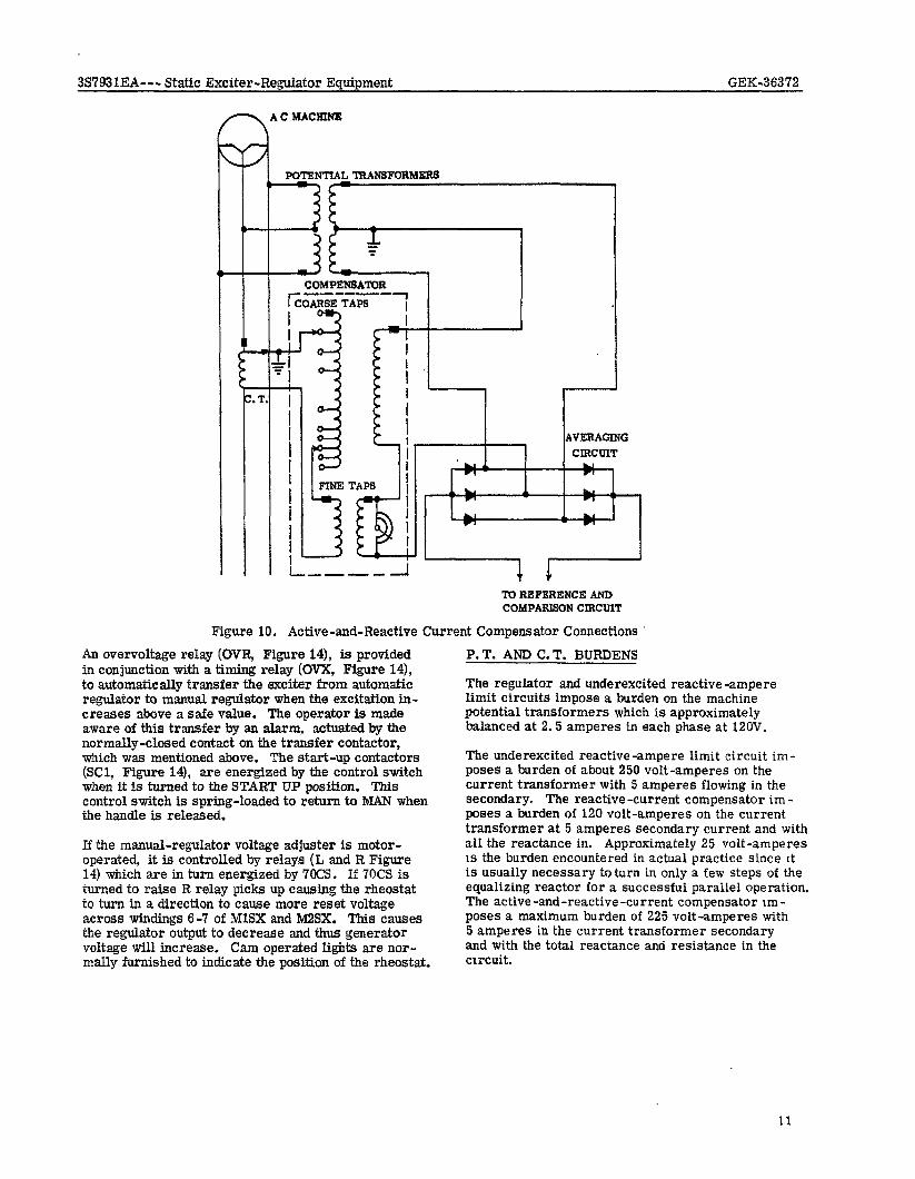
Figure 10. Active-and-Reactive Current Compensator Connections ’
An overvoltage relay (OVR, Figure 14), is provided in conjunction with a timing relay (OVX, Figure 14), to automatically transfer the exciter from automatic regulator to manual regulator when the excitation in- creases above a safe value. The operator is made aware of this transfer by an alarm, actuated by the normally-closed contact on the transfer contactor, which was mentioned above. The start-up contactors @Cl, Figure 14), are energized by the control switch when it is turned to the START UP position. This control switch is spring-loaded to return to MAN when the handle is released.
If the manual-regulator voltage adjuster is motor- operated, it is controlled by relays (L and R Figure 14) which are in turn energized by WCS. If 70CS is turned to raise R relay picks up causing the rheostat to turn in a direction to cause more reset voltage across windings 6-7 of MlSX and M2SX. This causes the regulator output to decrease and thus generator voltage will increase, Cam operated lights are nor- mally furnished to indicate the position of the rheostat.
P. T. AND C. T. BURDENS
The regulator and underexcited reactive -ampere limit circuits impose a burden on the machine potential transformers which is approximately balanced at 2.5 amperes in each phase at 12OV.
The underexcited reactive-ampere limit circuit im- poses a burden of about 250 volt-amperes on the current transformer with 5 amperes flowing in the secondary. The reactive -current compensator im - poses a burden of 120 volt-amperes on the current transformer at 5 amperes secondary current and with all the reactance in. Approximately 25 volt-amperes 1s the burden encountered in actual practice since It is usually necessary to turn in only a few steps of the equalizing reactor for a successful parallel operation. The active -and-reactive -current compensator Irn - poses a maximum burden of 225 volt-amperes with 5 amperes in the current transformer secondary and with the total reactance and resistance in the circuit.
11
3S7931EA--- Static Exciter-Regulator Equipment GEK-36372
INSTALLATlON LOCATION AND MOUNTING
The regulator components are usually supplied in an enclosing case destgned for floor mounting. This en- closure should be installed in a well-ventilated, clean, dry location where the normal ambient temperature is not greater than 50°C (122°F). CONNECTIONS
Connections must be made in accordance with the diagrams supplied with the equipment for each partic- ular installation. Care must be exercised to deter- mine that the connections are correct to avoid dam- aging the equipment.
The size of the interconnecting wires and cables will vary with the rating of the equipment. Minimum wire sizes are shown on the Elementary diagram.
Care should be taken that the d-c supply is connected with the polarity sh9wn. Reverse polarity will cause the motor on the manual-regulator voltage adjuster to rotate in the wrong directionfor a given position of the control switch. In addition, the start-up circuit blocking-rectifiers will prevent start-up current from flowing in the field circuit.
It is extremely important that the PPT’s and the SCT’s are connected with the polarity-marked ends as shown on the diagram. Failure to do so can cause damage to the equipment or improper operation of the circuit.
Instrument transformers, both current and potential, should be connected as shown in the diagram. The current transformers should be brought to the reg- ulators through a shorting device. POLARITY AND PHASE ROTATION
When making connections from the exciter to the reg- ulator, polarity should be carefully checked to make certain that the connections are the same as those shown on the applicable diagrg,m. Reactive and active- reactive current compensator polarities must be carefully observed when cannections are made. THE CURRENT TRANSFORMERS USED WITH THESE UNITS MUST BE LOCATED IN THE SAME PHASE AS THE SIGNAL-VOLTAGE WINDINGS.
INITIAL OPERATION, TEST, AND ADJUSTMENT
CONTROL CIRCUITS
Control circuits should be tested under such conditions that the excitation system will not affect the operation of the a-c machine. This can be done by leaving the field circuit breakers open..
The start-up circuit contactors can be checked by turning the 43 switch to the START-UP position. SC1 should pickup. To test the manual regulator voltage adjuster circuit. turn ‘7OCS (Figure 14) to the raise position. The ad- juster should turn in the direction to cause the re- sistance from NI22 to M6 to decrease.
12
Turning 70CS to the LOWER position should cause the manual-regulator voltage asjuster to turn in the di- rection to inCreaSe the resistance from M22 to M6.
To test the transferring and over-voltage portions of the regulator control circuit, turn the regulator con- trol switch (43, Figure 14) to AUTO. The transfer contactor (TRC, Figure 14), should pick up. Man- ually picking up the over-Joltage relay (OVR. Figure 14) should cause the over-voltage auxiliary relay (OVX, Figure 14), to pick up. Since this is a time delay relay nothing else should occur until the time delay period is over. Then, TRC should drop out and the light or alarm should indicate this on the con- trol board.
STATIC EXCITER
Manual Control
The static exciter - regulator should be tested with the a-c machine operating at normal speed, discon- nected from the system, with all field breakers open.
The regulator control switch should be in MAN and the manual-regulator voltage adjuster should be at the extreme LOWER end.
The next step is to close the main-exciter-field cir- cuit breaker. If the exciter voltage builds up to over 50 volts, open the field breaker end recheck polarities. It is expected that the exciter voltage will be near zero, and insufficient to build up the a-c machine line voltage. If this is true, the 43 switch should be turned to START UP, The exciter voltage and a-c machine voltage should build up and hold at 50% of machine rating or greater. If, after 5 or 6 seconds the voltage shows no signs of building up, release the 43 switch. turn the manual regulator voltage adjuster control switch to RAlSE, and try again. It should be remembered that the field circuit is highly inductive and the build- up will be slow. Therefore, it is imperative that all adjustment be made in small increments until the operator becomes familiar with the characteristics of the particular machine. Changing the manual voltage adjuster too much may cause the generator to build up to an excessive voltage.
Once the voltage has started to build up, it should be possible to control it by means of the manual regulator voltage adjuster. If the voltage adjuster has no con- trol over the voltage. i.e., voltage goes to a large value and stays, then check for correct sensing volt - age, correct SCR supply voltage. open rheostats in the comparison circuit or an open zener diode in the comparison circuit. If all voltages and components are correct then check MlP for too much resistance and M2P for too little resistance. MlP normally will be shorted out and will be used only to raise the value of minimum voltage obtainable with 7OP at full lower or to decrease the sensitivity of adjustment of 7OP at high loads. M2P will normally be shipped so that the maximum voltage obtainable from 7OP ad- justment is 120% of nominal field voltage (300 for a 250 volt field and 450 for a 375 volt field).
3S7931EA --- Static Exciter-Regulator Equipment GEK-36372
As a last resort if generator armature voltage is higher than desired, the reactance of the linear reactor can be increased. With a large ualue for XL. a given control current will cause a larger voltage drop across XL and thus field voltage will be reduced, It should be remembered that changing reactance affects ex- citer compounding.
Once voltage reaches an acceptable level and can be controlled with the voltage adjuster, armature volt- age and field voltage should be observed for oscilla- tion. If oscillations develop, M3P should be increased. Check the operation of the adjuster in the raise and lower direction to insure that generator voltage raises and lowers smoothly. The voltage adjuster switch is spring-loaded and should return to the NORMAL po- sition when the handle is released.
Paralleling With Spare Exciter
If the static exciter is to be used in parallel with a spare rotating exciter, transferring between spare and main exciters should be tried at this time. THIS TRANSFERRING MUST BEDONE WITH THE MAIN EXCITER OPEaTING ON THE MANUAL REGULA- TOR. With the generator field excited by the main exciter, adjust the spare exciter voltage until it is equal to or slightly higher than the main exciter volt- age and close the spare exciter field breaker. With the two exciters in parallel, alternately increase the spare exciter voltage and decrease the main exciter voltage. This should cause an increase in the spare exciter current and a decrease in the main exciter current. When the main exciter current is zero, we can open the main exciter field breaker. When the main exciter field breaker is opened, M4P should be in- serted and the voltage adjuster isolated by contacts of 41M. The shorting link from M22-M23 should have been removed and replaced by a normally open con- tact of 41M. A normally closed contact of 41M is used from M23 - M24. M4P is used to give a constant output voltage from the manual regulator. M4P should be adjusted to give nominal control current in the SCT control winding in order to minimize snubbing resistor heating.
Transferring from spare exciter to main exciter can be accomplished in the same manner, except that the spare exciter breaker should be opened before the current gets to zero, to prevent motoring the spare exciter. If the transfer is not smooth, do not pro- ceed until the trouble has been corrected.
Automatic Control .
The underexcited reactive-ampere limit amplifier should be removed from service by disconnecting the wire from terminal E8, Figure 14.
The reactive-current compensator knobs should be turned to the zero position and also the knobs of the active -and -reactive -current compensator, if fur - nished.
With the machine at rated voltage and rated speed, the 43 switch may be turned to the TEST position and the
automatic regulator checked. By turning the auto- matic-regulator voitage adjuster, it should be pos- sible to zero the transfer voltmeter (2VM, Fig. 14). The automatic -regulator voltage adjuster should be varied both ways from this position to make certain that the regulator is operating properly. The trans- fer voltmeter should be deflected from the center position to the right when the automatic-regulator vo age adjuster is turned in a “lower” (CCW) direction. If the operation of the automatic-regulator voltage adjuster must be reversed, it may be changed as follows, after the regulator control switch has been returned to MAN.
The external connections to the two terminals of the voltage regulator panel which connect to the ends of the voltage adjusting unit may be interchanged. (The connection from the voltage regulator panel to the slider on the voltage adjusting unit should not be changed.) The control switch should then be turned to TEST and the operation of the automatic-regulator voltage adjuster unit rechecked to determine that it is satisfactory.
Voltage Level
The automatic-regulator is designed and transformer ratios are selected to give a nominal signal voltage of approximately 115 volts to the three-phase bridge consisting of diodes A7D through A12D. The auto- matic regulator voltage adjuster should provide ad- justment of at least 7.5 percent above and below the nominal signal voltage for turbine generators. It is usually preferable to delay the final voltage-level adjustment until the under-excited reactive-ampere limit has been reconnected, since it may affect the automatic-regulator voltage adjuster setting for a given voltage. In addition, the reactive-current corn pensator, and the active-and-reactive-current com- pensator may appreciably alter the signal voltage after they have been adjusted. Polarity Tests
Before the a-c regulator is first placed tn control of the a-c machine excitation, it is recommended that final polarity tests be conducted. To check the stabilizing connections, put the regulator control switch at TEST. With the a-c machme operatmg at normal speed and voltage, and under the control of tt manual regulator, disconnect the lead bringing ex- citer feedback to the SCR circuit. (R88. Figure 14). Discharging capacitor A2C, then puttmg the lead back on should cause the transfer voltmeter to deflect to the right. If this voltmeter deflects in the wrong direction, locate and correct the trouble befor proceeding.
The reactive -current compensator polarity must be checked, before putting the regulator in service, with an a-c machine which is connected to the systen Turn the compensator adjusting knobs to the zero position and operate the machine overexcited at normal voltage.
With the regulator control switch at TEST, adjust the automatic-regulator voItage adjuster until the transfer meter is at 0. Turn the compensator
13
3S7931EA--- Static Exciter -Regulator Equipment GE&36372 1
“coarse” knob to the right to insert reactance. The transfer voltmeter should deflect to the right. If it deflects to the left, the current transformer leads to the compensator must be reversed and the test repeated. When the polarity of the compensator is correct, turn the “coarse” knob back to 0, and set the “fine” knob to 4. It is then possible to proceed with the automatic-regulator tests. The transfer meter should deflect to the left if the preceding test is made with an active-and-reactive-current com- pensator.
INITIAL OPERATION
It is recommended that the following tests be made with the a-c machine disconnected from the load or system; if the a-c machine must be connected to the system, it should be operated at a light load. For complete information on placing the regulator in service and removing it from service, refer to the section titled “Operation”.
With the a-c machine operating at normal speed and voltage and with the regulator control switch at TEST, adjust the transferring voltage on the transfer volt- meter (ZVM, Fig. 14), to zero. The regulator con- trol switch may then be turned to AUTO. This will then put the automatic-regulator in control of the a-c machine excitation. There should be no change in a-c machine voltage. If the voltage changes ap- preciably, immediately turn the control switch to MAN and determine the cause of the incorrect opera- tion. If the transfer voltmeter (2VM) or the SCT saturating current ammeter (ClM) exhibits a gradual change resulting in oscillations which grow steadily greater, the stabilizing connections or adjustment of the stabilizing circuit may be incorrect. The polarity of the stabilizing circuit should be rechecked. If these are found to be correct, attempt to obtain stable operation by adjusting the rheostat in series with the capacitor. Reduce the resistance to a value that is about 15 percent less than the original value and again place the regulator in control of the a-c machine ex- citation. If the stability still has not improved, re- peat the preceding adjustment using larger and smaller values of resistance. It should be possible to stabilize the regulator by gradual adjustments of this rheostat. However, if the regulator still is unstable after the full range of resistance has been tried, the exciter- stabilizer-capacitors should be added and disconnect- ed one at a time. (Refer to the connection diagram supplied with the equipment.) After each change the resistance should be adjusted in the same manner as previously described.
AH adjustments must be made with the con- trol switch at “man”.
With the regulator-control switch at AUTO, turn the automatic-regulator voltage adjuster in the clockwise direction. The transfer voltmeter should change slightly to the left and the exciter voltage and a-c
14
terminal voltage should rise. Next, turn the auto- matic-regulator voltage adjuster in counter-clockwise direction. The transferring voltmeter should deflect to the right and the exciter voltage and the a-c ma- chine terminal voltage should fall. If the a-c machine is a generator which is not connected to a load or a system, the voltage-adjusting rheostat may be operat- ed to obtain a total change in machine voltage of at least 15% of rated voltage.
Refer to the section titled “Operation” for instructions on removing the regulator from control of a-c ma- chine excitation.
When proper regulator operation has been secured, optimum stability should be checked and the necessary adjustments made.
Optimum Regulator Stability
The following test should enable a quick determination of optimum stability. Place the regulator in control of a-c machine excitation. -After suddenly turning the automatic-regulator voltage adjuster a few degrees in the lower direction, the transfer voltmeter will indicate only two or three oscillations and the a-c machine voltmeter will overshoot only slightly be- fore returning to a new steady value.
Before making any adjustments in the stabilizer circuit, it is necessary to turn the regulator control switch to “Man”, and follow the procedure outlined under “Initial Operation. ”
Regulator Sensitivity and Voltage Regulation
Determination of a-c machine voltage regulation with the regulator in service is a difficult procedure under usual operating conditions and one which will pro- duce only qualitative results. Since the regulator is adjusted at the factory to provide adequate sensi- tivity for close regulation, this measurement is usually unnecessary at the time of installation, and for this reason no special test procedure is given. After the equipment has been placed in service, it is possible to obtain data which will provide a mea- sure of voltage regulation, but results must be care- fully interpreted to gain a reliable estimate of per- formance.
If the machine is connected to a system, the regula- tion will depend to a great extent upon the character- istics of this system. Regulation will also be con- siderably affected by the use and adjustment of com- pensators. Furthermore, the sensitivity of the re- gulator itself will be a major factor affecting voltage regulation, A method is given in a later section for measuring regulator sensitivity.
3S793IEA--- Series Static Exciter-Regulator Equipment GEK-36372
UNDEREXCITED REACTIVE AMPERE LIMIT (If Furnished)
Limit Polarity
After satisfactory operation of the regulator has been obtained, the reactive-ampere limit should be tested. Reconnect the limit amplifier to the regulator, set the REACTIVE AMPERE LIMIT POWER RECALIBRA- TION switch at zero and the REACTIVE AMPERE LIMIT START dial at its highest numbered position.
With the machine carrying power load, and some safe value of underexcited reactive current move the re- gulator control switch to TEST. Adjust the automatic- regulator voltage adjuster until the transfer voltmeter reads 0. Slowly turn the REACTIVE AMPERE LIMIT START dial toward 0. At some setting of the dial, the limit-detector meter reading will go to 0 and increase in the opposite direction. Limit signal-current will increase from 0 and the transfer voltmeter will de- flect to the left. If the limit-detector current does not reverse before the dial has been turned to zero, re- turn the dial to the highest numbered position. De- crease the a-c machine excitation to further increase the underexcited current, being careful not to exceed the safe operating limit for the machine. It may be desirable to reconnect the limit to operate on over- excited reactive current as described in “Reactive Ampere Sensitive Circuit” in a previous section.
Again turn the REACTIVE AMPERE LIMIT START dial towards zero until the limit detector current is 10 MA. If the signal cannot be increased from zero by turning the REACTIVE AMPERE LIMIT START dial to zero, the limit polarity may be reversed. Turn the regulator control switch to MAN and re- verse the primary connections of transformer E3T (Fig. 14). Repeat the test previously described to determine if reverse limit-detector current can be obtained by turning the REACTIVE AMPERE LIMIT START dial towards zero. THIS TEST MUST GIVE PROPER RESULTS BEFORE FURTHER TESTS ARE CONDUCTED. If the limit signal-current had an initial value that went to zero as the REACTIVE AM- PERE LIMIT START dial setting was reduced, the input to the limit amplifier must be reversed. If the transfer voltmeter deflected to the right, the limit d-c output is reversed. Reverse the connections between the limit amplifier and the first stage ampli- fier of the automatic -regulator. (See connection dia- grams furnished with the equipment. ) Repeat the previously described tests to secure proper results.
With the REACTIVE AMPERE LIMIT START dial so set that the transfer voltmeter did deflect slightly to the left of 0, turn the POWER RECALIBRATION switch from point 0 toward point 9. If the a-c machine is delivering power, the transfer voltmeter should deflect more to the left as the POWER RECALIBRA- TION switch is turned toward point 9.
Turn the POWER RECALIBRATION switch to 0. Re- adjust the transfer voltmeter to approximately 10 volts to the left with the REACTIVE AMPERE LIMIT START dial. Before proceeding further with the tests on the
underexcited reactive limit circuit, it is necessary to check the polarity of the LIMIT stabilizing circuit. Carefully disconnect one of the exciter voltage stabi- lizing leads from the LIMIT amplifier and short the stabilizing input terminals on the LIMIT amplifier (refer to the connection diagrams supplied with each equipment). This should cause the transfer voltmeter to deflect more to the left. Replacing the primary lead should cause the transfer voltmeter to deflect to the right. Do not proceed with the underexcited re- active-ampere limit tests until the polarity of the limit stabilizer is correct.
Turn the REACTIVE AMPERE LIMIT START dial to its highest reading. Readjust the transfer voltmeter reading to zero with the automatic-regulator voltage adjuster. Operate the a-c machine at normal volt- age and with underexcited reactive current. Turn the regulator control switch to AUTO as discussed under “Initial Operation”. Slowly turn the REACTIVE AMPERE LIMIT START dial toward zero. The transfer voltmeter should deflect slightly to the left and the exciter voltage should increase, causing the underexcited reactive current to decrease. The dial setting at which the underexcited reactive current starts to decrease is the limit-start point. If the operation is not as described, immediately remove the regulator from control of the a-c machine ex- citation by turning the regulator-control switch to MAN. Repeat the limit polarity tests. Do not pro- ceed further until satisfactory operation is obtained.
With the regulator control switch at AUTO and the REACTIVE AMPERE LIMIT START dial at the limit- start point, observe the transfer voltmeter, the ex- citer voltmeter, and the a-c machine ammeter for signs of oscillation. If oscillations of the reactive current or transfer voltmeter voltage appear, remove the automatic-regulator from control of the machine excitation by turning the regulator control switch to MAN. Adjust the resistance in series with the ex- citer LIMIT stabilizing capacitors in 15 percent steps, first in the direction to decrease resistance and then in the direction to increase resistance. After each of these adjustments repeat the procedure for putting the LIMIT in service as previously described, being very careful to observe the transfer meter voltage and exciter voltage oscillations and reactive-current oscillations. However, if the LIMIT still is unstable after the full range of resistance has been tried, the exciter stabilizer capacitors on the LIMIT amplifier should be added and disconnected one at a time. After each change the resistance should be adlusted in the same manner as previously described.
After stable operation of the LIMIT has been obtained, check the LIMIT operation as follows with the re- gulator in control of a-c machine excitation. Move the REACTIVE AMPERE LIMIT START dial to the limit-start point. Record the reactive current. De- crease the underexcited reactive-ampere load on the a-c machine by operating the automatic-regulator voltage adjuster to raise the voltage. The under- excited reactive current should decrease. It should be possible to adjust the underexcited reactive cur- rent to any value lower than it was at the limit-start
15
3S’793IEA--- Series Static Exciter-Regulator Equipment GEK-363’72
point. Now increase the underexcited reactive cur- rent by turning the automatic-regulator voltage ad- luster to lower the voltage. As the limit-start point is passed, the exciter voltage should increase and it should be impossible to raise the underexcited re- active current appreciably above the previously re- corded value no matter how far the automatic-regula- tor voltage adjuster is turned in the direction to lower voltage.
As a final check of optimum LIMIT stability, move the REACTIVE AMPERE LIMIT START dial until the transfer voltmeter reads approximately 10 volts to the left. Abruptly, move the automatic-regulator voltage adjuster a few degrees in the lower direction and observe carefully the transfer voltmeter and the reactive-current ammeter for signs of oscillations. If oscillations appear, adjust for optimum stability as previously outlined. When the transfer voltmeter and the reactive-current ammeter show only a few oscillations after an abrupt change of the automatic- regulator voltage adjuster, the LIMIT stability is satisfactory. Move the REACTIVE AMPERE LIMIT SENSITIVITY dial slowly toward its highest scale reading. Again check the LIMIT stability.
This completes the preliminary adjustment of the LIMIT. Final adjustment can be made at any time.
Final Adjustment of The Underexcited Reactive-Am- pere Limit
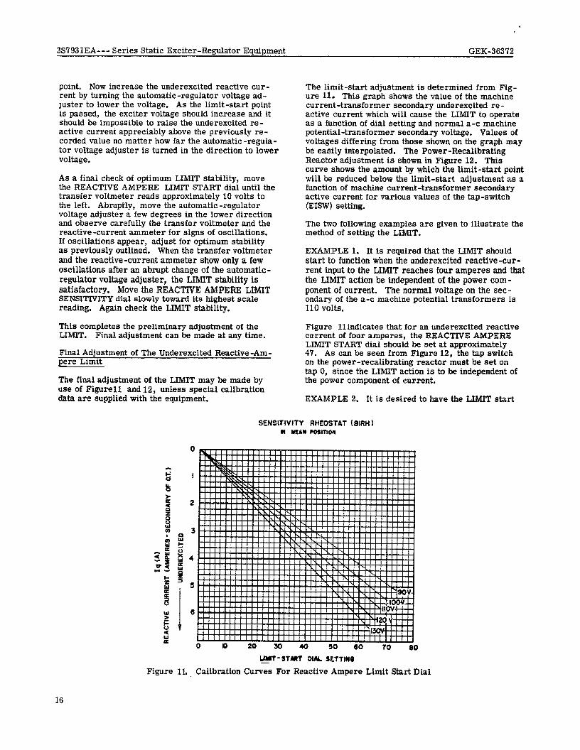
The final adjustment of the LIMIT may be made by use of Figure11 and 12, unless special calibration data are supplied with the equipment.
The limit-start adjustment is determined from Fig- ure 11. This graph shows the value of the machine current-transformer secondary underexcited re- active current which will cause the LIMIT to operate as a function of dial setting and normal a-c machine potential-transformer secondary voltage. Values of voltages differing from those shown on the graph may be easily interpolated. The Power -Recalibrating Reactor adjustment is shown in Figure 12. This curve shows the amount by which the limit-start point will be reduced below the limit-start adjustment as a function of machine current-transformer secondary active current for various values of the tap-switch (EISW) setting.
The two following examples are given to illustrate the method of setting the LIMIT.
EXAMPLE 1. It is required that the LIMIT should start to function when the underexcited reactive-cur- rent input to the LIMIT reaches four amperes and that the LIMIT action be independent of the power com- ponent of current. The normal voltage on the sec- ondary of the a-c machine potential transformers is 110 volts.
Figure llindicates that for an underexcited reactive current of four amperes, the REACTIVE AMPERE LIMIT START dial should be set at approximately 47. As can be seen from Figure 12, the tap switch on the power-recalibrating reactor must be set on tap 0, since the LIMIT action is to be independent of the power component of current.
EXAMPLE 2. It is desired to have the LIMIT start
sEr4smvrrY RHEOSTAT (BIRH 1 CI WAN COIITION
Figure 11. _ Calibration Curves For Reactive Ampere Limit Start Dial
16

3S7931EA--- Series Static Exciter-Regulator Equipment GEK-36372
Ip (S) AGWE aiRRENT (AMPERES - SECONDIRY OF Cl) powER RECAt,eRAtfON
SWITCH POSITlOW
2 I!$ t
3
NO.9
2.6 NO.6
NO.7 “2 k” 2
a &a
NO.6
a= z!- i 5 1.5 NO.6
0 pg NO.4
so -i ’ NO.3
!z::
E 8 36
NO. 2 -6
8 NO, I
i2 Q ‘.‘-.“‘-...-------’ NO.0 0 I 2 3 4 5
Figure 12 . Calibration of Reactive-Ampere Power Recalibration Limit Circuit
to function when the underexcited reactive-current in- put to the LIMIT reaches four amperes with zero active amperes, and when the underexcited reactive- current input reaches three amperes with four active amperes.
Figure 11 indicates, that for an underexcited reactive current of four amperes, the REACTIVE AMPERE LIMIT START dial should be set at approximately 47. This satisfies the requirement at zero active amperes. Now, the number of reactive amperes necessary to start the limit at four active amperes must be reduced by one reactive ampere to obtain the desired power recalibration. Therefore, in Figure 12, a value of one reactive-ampere recalibration of the LIMIT and four active amperes to the LIMIT, indicates that tap switch EISW should set at tap 4.
If desired, before making the Final adjustment of the LIMIT, the calibration curves (Figure 11 and 12 ) may be checked in the following manner.
Place Power - Recalibrating Reactor tap switch EISW on tap 8. Place the REACTIVE AMPERE LIMIT START dial at its highest scale position. Put the auto- matic regulator in control of the a-c machine excita- tion. With the a-c machine carrying some convenient power Ioad at about unity power factor, move the REACTIVE AMPERE LIMIT START dial slowly toward
zero. At some position of the dial, the LIMIT will start to operate. This position will be that which will just start to decrease the machine under-excited reactive-current, or increase the overexcited re- active current.
Determine the active and reactive amperes delivered by the mathine current transformer to the LIMIT. Draw a vertical line from the active-ampere scale point in Figure 12 to the curve for tap 8. Read the corresponding reactive amperes recalibration of the LIMIT, and the setting of the REACTNE AMPERE LIMIT START dial.
In Figure 11 use the dial setting and the proper a-c voltage curve to determine the value of underexcited reactive current for which the LIMIT is set. From this value, subtract the reactive amperes recali- bration. The result should be essentially equal to the reactive amperes delivered to the limit if the test has been carefully conducted.
Set the LIMIT adjustments to the points which are desired for final operation. If it is desired to check the adjustments, the following procedure may be followed.
Place the automatic regulator in controlof the a-c machine excitation. Operate the machine at the
17
3S7931EA--- Series Static Exciter-Regulator Equipment GEK-36372
desired power load and at a reactive load which should not cause LIMIT operation. Turn the automatic re- gulator voltage adjuster in the direction to lower volt- age until the LIMIT prevents further reduction in ma- chine overexcited reactive current, or increase in underexcited reactive current. Determine the value of reactive current and active current supplied by the machine current. transformer to the LIMIT.
Knowing the a-c machine voltage and the setting of the REACTIVE AMPERE LIMIT START dial, deter- mine the underexcited reactive current setting from Figure l? Determine the underexcited reactive am- pere recalibration from Figure 12. The result of subtracting the value of underexcited reactive am- peres read in Figure 12 from the value of underexcited reactive amperes read in Figure 11 will be essentially equal to the value of underexcited reactive current to the LIMIT at the limit-start point.
REACTIVE -CURRENT COMPENSATOR
The polarity of the reactive-current compensator is checked as described under “Initial Operation”. Final adjustment of the compensator can only be made after considerable experience with the machine operating under control of the automatic regulator. It is de- sirable to keep the amount of reactance used to the minimum required for proper division of reactive kva between machines to avoid excessive voltage regula- tion. As an initial adjustment, it is frequently de- sirable to turn the “fine” knob to position 4 with the “coarse” knob at zero. Adjustments may be made with the compensator current transformer energized. When making adjustments, the a-c machine power factor should swing toward unity as the reactance of the compensator is increased.
ACTIVE-AND-REACTIVE CURRENT COMPENSATOR
Turn both adjusting knobs to 0 and operate the a-c machine overexcited (lagging power factor). With the regulator control switch at TEST and the transfer volt- meter reading 0, turn the f’coarseV’ reactance-adjust- ment knob to the right to insert reactance; the trans- fer voltmeter should be deflected to the left. Re- turn the “coarse” reactance-adjustment knob to 0 and turn the “coarse” resistance-adjustment knob to the right to increase resistance; this should also cause the transfer voltmeter to deflect to the right. If the trans- fer voltmeter deflects in the wrong direction, the compensator current leads must be interchanged and the tests repeated.
Final adjustment of the compensator must be made on the basis of experience. Preliminary adjustment may be made in accordance with the known values of resistance and reactance for that portion of the sys- tem over which compensation is desired. If the voltage at the point which is to be compensated de- creases as the power factor becomes more lagging and increases as the power factor becomes less lagging, more reactance and possibly less resistance may be required. Adjustments may be made with the compensator and automatic regulator in service.
18
GAIN MEASUREMENTS
The automatic regulator gain should be checked only when it is thought that the system is not operating properly. If the gain is to be checked it will be nec- essary to use a laboratory type meter to measure the change in voltage on the secondary of the PT’s; the ratio of the change in voltage across points A9 andAlO(See Fig. 14.) to the voltage change at the PT secondaries is the gain of the SCR circuit. The voltage across A9 andAlOis the output of the SCR circuit.
SYSTEM SELF-COMPENSATION
It is necessary to determine the degree of self-com- pensation of this system to be certain that the linear reactors are set at the best taps. This can be &ne by measuring the value of current through the SCT control winding at no-load and at full load, rated power factor. The degree-of-correction(DOC) is the change in control current divided by the no-load value of control current. If the control current decreases from no-load to full load, the system is under-com- ponded If the current increases, the system is over- compounded. It should be possible, with the taps available, to limit DOC between 5% under-compounded to 20% over -compounded.
Changing..the linear reactors to a higher reactance tap causes increased compensation, i. e., it tends to over-compound the system. CHANGE TAPS ON ALL THREE PHASES OF THE DEVICE BEING ADJUSTED.
.OPERATlON NORMAL OPERATION
General
The complete voltage-regulator equipment should be placed in normal service with the a-c machine only after the control circuits, regulator, underexcited reactive-ampere limit, reactive-current compensator, and active -and -reactive current compensator have been properly tested in general conformance with the previously described instructions. Final adjustment of these units may, of course, be delayed until operat- ing experience has been obtained, but circuits which have not been thoroughly tested must not be employed with the automatic-regulator in service if the possibil- ities of damage to the equipment and disturbance of the system are to be avoided.
Operation With Attended Equipment
In attended stations, the a-c machine must be brought up to normal speed and voltage under control of the manual-regulator before the automatic-regulator is placed in service, Generators are frequently con- nected to the load or system before the automatic re- gulator is used, but this is not essential, since this regulator may be placed in service with the machine under any load condition and with the machine con- nected to or disconnected from the system.
3S7931EA--- Series Static Exciter-Regulator Equipment GEK-36372
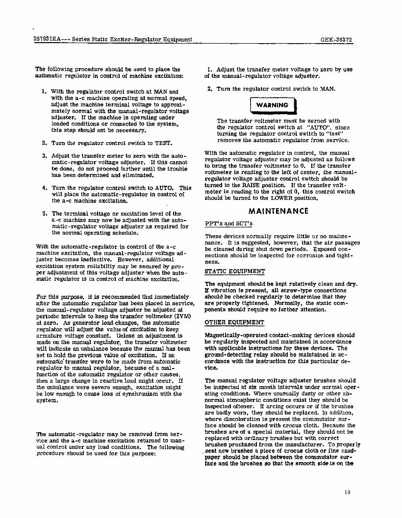
The following procedure should be used to place the autbmatic regulator in control of machine excitation:
1.
2.
3.
4.
5.
With the regulator control switch at MAN and with the a-c machine operating at normal speed, adjust the machine terminal voltage to approxi- mately normal with the manual-regulator voltage adjuster. If the machine is operating under loaded conditions or connected to the system, this step should not be necessary.
Turn the regulator control switch to TEST.
Adjust the transfer meter to zero with the auto- matic-regulator voltage adjuster. If this cannot he done, do not proceed further until the trouble has been determined and eliminated.
Turn the regulator control switch to AUTO. This will place the automatic-regulator in control of the a-c machine excitation.
The terminal voltage or excitation level of the a-c machine may now be adjusted with the auto- matic-regulator voltage adjuster as required for the normal operating schedule.
With the automatic-regulator in control of the a-c machine excitation, the manual-regulator voltage ad- juster becomes ineffective. However, additional excitation system reliability may be secured by pro- per adjustment of this voltage adjuster when the auto- matic regulator is in control of machine excitation.
For this purpose, it is recommended that immediately after the automatic regulator has been placed in service, the manual-regulator voltage adjuster be adjusted at periodic intervals to keep the transfer voltmeter (2VM) at zero. As generator load changes, the automatic regulator will adjust the value of excitation to keep armature voltage constant. Unless an adjustment is made on the manual regulator, the transfer voltmeter will indicate aa unbalance because the manual has been set to hold the previous value of excitation. If an automatlc’transfer were to be made from automatic regulator to manual regulator, because of a mal- function of the automatic regulator or other causes, then a large change in reactive load might occur. If the unbalance were severe enough, excitation might be low enough to cause loss of synchronism with the system.
The automatic-regulator may be removed from ser- vice and the a-c machine excitation returned to man- ual control under any load conditions. The following procedure should be used for this purpose:
1. Adjust the transfer meter voltage to zero by use of the manual-regulator voltage adjuster.
2. Turn the regulator control switch to MAN.
The transfer voltmeter must be zeroed with the regulator control switch at “AUTOf’, since turning the regulator control switch to “test” removes the automatic regulator from service.
With the automatic regulator in control, the manual regulator voltage adjuster may be adjusted as follows to bring the transfer voltmeter to 0. If the transfer voltmeter is reading to the left of center, the manual- regulator voltage adjuster control switch should be turned to the RAISE position. If the transfer volt- meter is reading to the right of 0, this control switch should be turned to the LOWER position.
MAINTENANCE PPT’s and SCT’s
These devices normally require little or no mainte- nance. It is suggested, however, that the air passages be cleaned during shut down periods. Exposed con- nections should be inspected for corrosion and tight- ness. STATIC EQUIPMENT
The equipment should be kept relathely clean and dry. If vibration is present, all screw-type connections should be checked regularly to determine that they are properly tightened. Normally, the static com- ponents should require no further attention.
OTHER EQUIPMENT
Magnetically-operated contact-making devices should be regularly inspected and maintained in accordance with applicable instructions for these devices. The ground-detecting relay should be maintained in ac- cordance with the instruction for this particular de- vice.
The manual regulator voltage adjuster brushes should be inspected at six month intervals under normal oper- ating conditions. Where unusually dusty or other ab- normal atmospheric conditions exist they should be inspected oftener. If arcing occurs or if the brushes are badly worn, they should be replaced. In addition, where discoloration 1s present the commutator sur- face should be cleaned with crocus cloth. Because the brushes are of a special material, they should not be replaced with ordinary brushes but with correct brushes pruchased from the manufacturer. To properly seat new brushes a piece of crocus cloth or fine sand- paper should be placed between the commutator sur- face and the brushes so that the amooth side ie on the
19
38793 lEA--- Series Static Exciter-Regulator Equipment GEK-36372
commutator surface and the abrasive side is against the brushes. While holding the cloth or sandpaper tightly in place rotate the brush holder and brushes through a short arc. Blow out the carbon particles which have been removed. Remove the cloth or sand- paper and rotate the brush holder through its range of travel several times to check for smooth travel of the brushes over the commutator surface. The brushes should fit flat over the entire commutator range. No space should be visible between the brushee and the commutator surface. This same procedure should be followed with the automatic regulator volt- age adjuster rheostat.
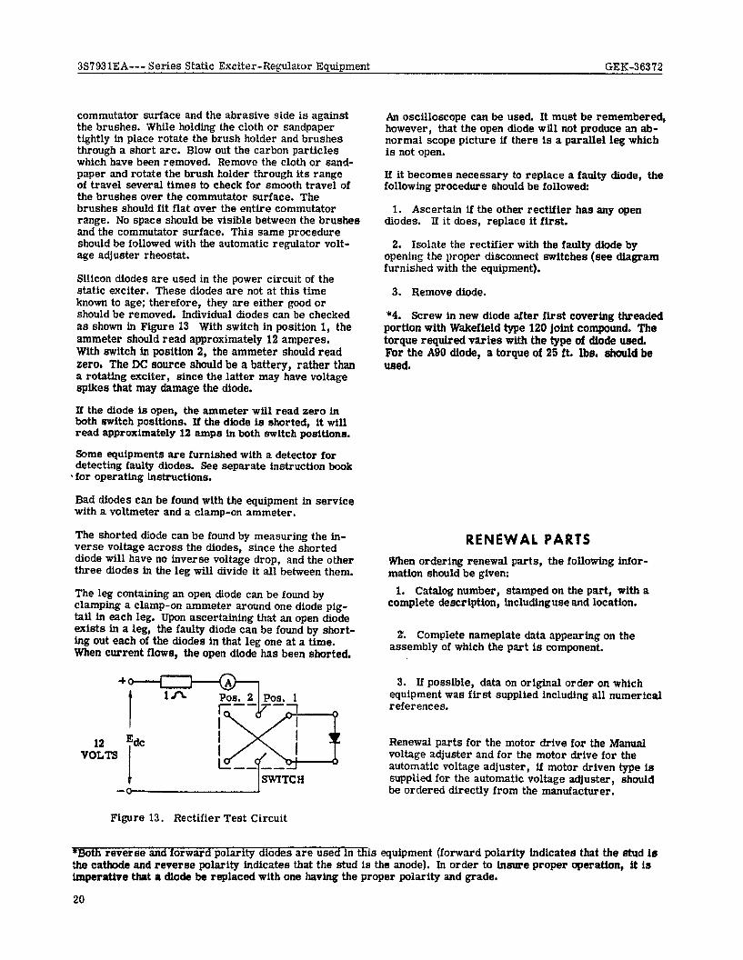
Silicon diodes are used in the power circuit of the static exciter. These diodes are not at this time known to age; therefore, they are either good or should be removed. Individual diodes can be checked as shown in Figure 13 With switch in position I, the ammeter should read approximately 12 amperes. With switch in position 2, the ammeter should read zeroI The DC source should be a battery, rather than a rotating exciter, since the latter may have voltage spikes that may damage the diode.
If the diode is open, the ammeter will read zero in both switch positions. Xt the diode is shorted, lt will read approximately 12 amp8 in both switch positions.
Some equipments are furnished with a detector for detecting faulty diodes. See separate instruction book
‘for operating tnstructions.
Bad diodes can be found with the equipment in service with a voltmeter and a clamp-on ammeter.
The shorted diode can be found by measuring the in- verse voltage across the diodes, since the shorted diode will have no inverse voltage drop, and the other three diodes in the leg will divide it all between them.
The leg containing an open diode can be found by clamping a clamp-on ammeter around one diode pig- tail in each leg. Upon ascertaining that an open diode exists in a leg, the faulty diode can be found by short- ing out each of the diodes in that leg one at a time. When current flows, the open diode has been shorted.
‘-Ii-iTIGH - 1
Figure 13, Rectifier Test Circuit
An oscilloscope can be used. It must be remembered, however, that the open diode will not produce an ab- normal scope picture if there is a parallel leg which is not open.
If it becomes necessary to replace a faulty diode, the following procedure should be followed:
1. Ascertain if the other rectifier has any open diodes. If it does, replace it first.
2. Isolate the rectifier with the faulty diode by opening the proper disconnect switches (see diagram furnished with the equipment).
3. Remove diode.
*4. Screw in new diode after first covering threaded portion with Wakefield type 120 joint compound. The torque required varies with the type of diode used, For the A90 diode, a torque of 25 ft. Ibe. should be used.
RENEWAL PARTS When ordering renewal parts, the following infor- mation should be given:
1. Catalog number, stamped on the part, with a complete description, includinguse and location.
2. Complete nameplate data appearing on the assembly of which the part is component.
3. If possible, data on original order on which equipment was first supplied including all numerical references.
Renewal parts for the motor drive for the Manual voltage adjuster and for the motor drive for the automatic voltage adjuster, if motor driven type is supplied for the automatic voltage adjuster, should be ordered directly from the manufacturer.
*Both reverse and forward polarity diodes are used in this equipment (forward polarity indicates that the stud 1s the cathode and reverse polarity indicates that the stud la the anode). In order to insure proper operation, it is imperative that a diode be replaced with one having the proper polarity and grade.
20
3S7931EA--- Series Static Exciter-Regulator Equipment GEK-363’72
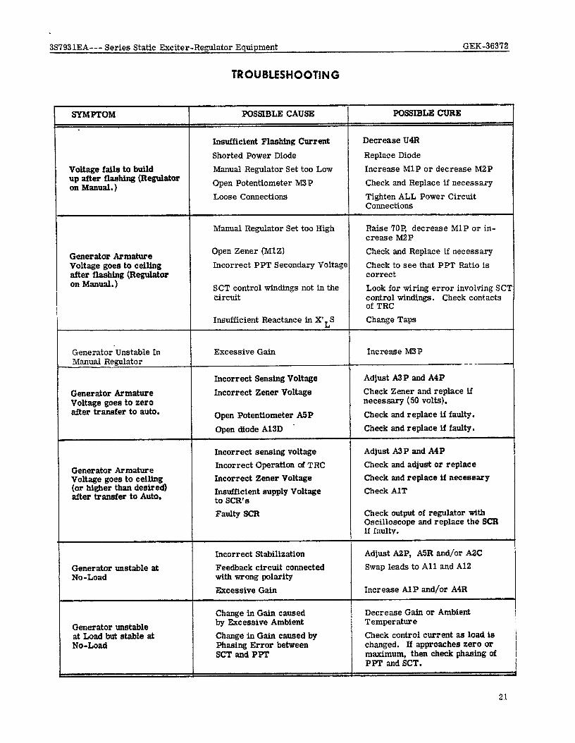
TROUBLESHOOTlNG
SYMPTOM ,
roltage fails to build up after flashing (Regulator m Manual.)
POSSIBLE CAUSE
Insufficient Flashing Current Shorted Power Diode
Manual Regulator Set too Low Open Potentiometer h43P Loose Connections
POSSIBLE CURE
Decrease U4R
Replace Diode
Increase MlP or decrease M2P Check and Replace if necessary
Tighten ALL Power Circuit Connections
Manual Regulator Set too High Raise 76P, decrease MlP or in- crease M2P
3ener ator Armature Voltage goes to ceiling titer flashing (Regulator In Manual.)
Open Zener (MlZ) Incorrect PPT Secondary Voltage
SCT control windings not in the circuit
Insufficient Reactance in XfLS
Check and Replace if necessary Check to see that PPT Ratio is correct Look for wiring error involving SC? control windings. Check contacts of TRC Change Taps
Generator-Unstable In Manual Regulator
Generator Armature Voltage goes to zero after transfer to auto.
Generator Armature Voltage goes to ceiling (or higher than desired) after transfer to Auto.
Excessive Gain
Incorrect Sensing Voltage
Incorrect Zener Voltage
Open Potentiometer A5P Open diode A13D .
Incorrect sensing voltage Incorrect Operation of TRC Incorrect Zener Voltage Insufficient supply Voltage to SCR’S Faulty SCR
Increase M3P -_--
Adjust A2P and A4P Check Zener and replace if necessary (50 volts). Check and replace if faulty. Check and replace if faulty.
Adjust A3P and A4P Check and adjust or replace Check and replace if necessary Check AlT
Check output of regulator with Oscilloscope and replace the SCR if I ;m1tv.
Generator unstable at No-Load
Generator unstable at Load bat stable at No-Load
Incorrect Stabilization Feedback circuit connected with wrong polarity Excessive Gain
Change in Gain caused by Excessive Ambient Change in Gain caused by Phasing Error between SCT and PPT
Adjust A2P, A5R and/or A2C Swap leads to All and Al2
Increase AlP and/or A4R
Decrease Gain or Ambient Temperature Check control current as load is changed. If approaches zero or maximum, then check phasing of PPT end SCT.
21
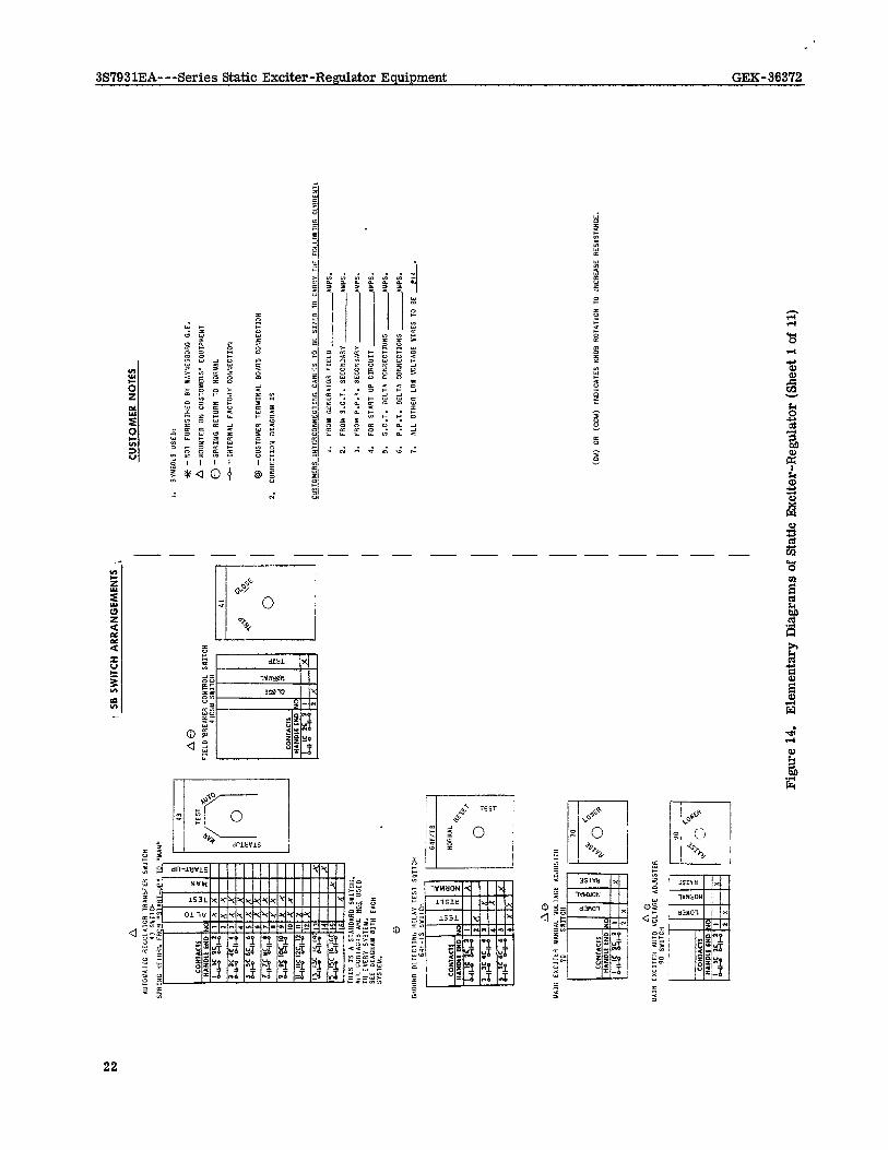
I SB
SW
ITCH
AR
RANG
EMEN
TS
1,
CUST
OMER
NO
TES
Figu
re
14.
Elem
enta
ry
Dia
gram
s of
Sta
tic E
xcite
r-Reg
ulat
or
(She
et 1
of
11)
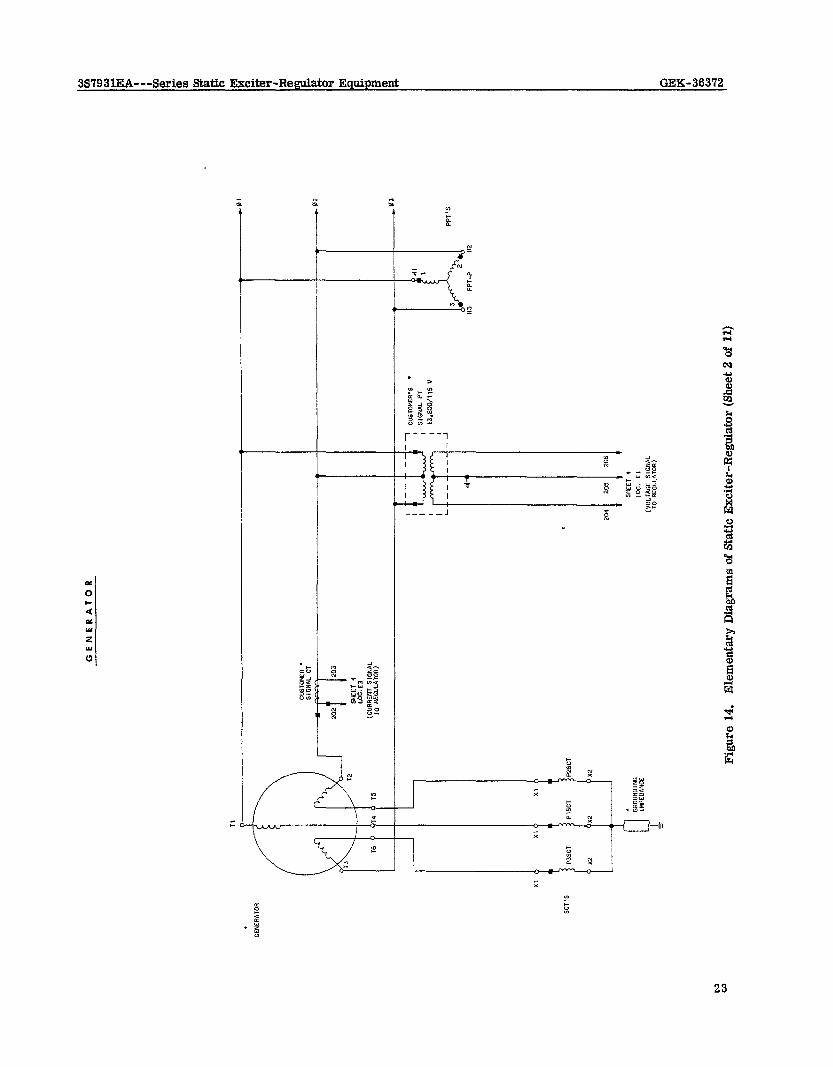
GENE
RATO
R
-
x1
lSCT
!S
CT
204
J-l-.-
--
*of
Figu
re
14.
Elem
enta
ry
Dia
gram
s of
Sta
tic E
xcite
r-Reg
ulat
or
(She
et 2
of
11)
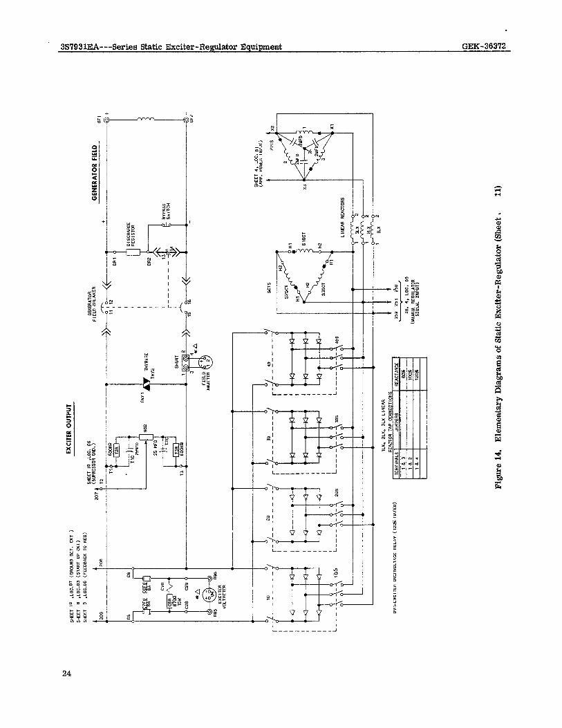
Y
EXCI
TER
OUTP
UT
GENE
RATO
R FI
ELD
BREA
KER
GENE
RATO
R FI
ELD
-----+
-;Tti<
WI
+ --
+ OR
1 I
Y
Figu
re
14.
Elem
enta
ry
Dia
gram
s of
Sta
tic E
xcite
r-Reg
ulat
or
(She
et ,
11
)
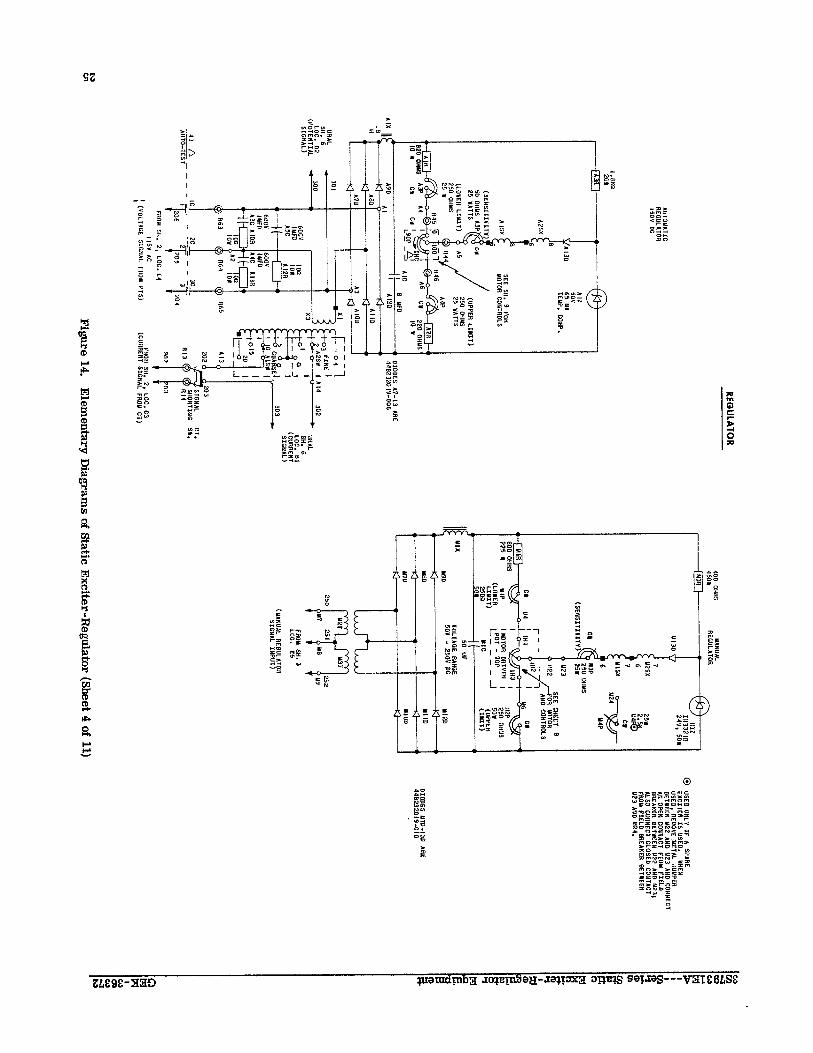
OIO
-610
wzf
lbC
3”
aE
I-a‘N
s3
aom
bOZ_
tl G
OA
90
-iFi- 3
L T
T 15
31~0
1””
----
~-~
, v
C@
900-
61
OZEZ
WP
39”
6,-L
” S3
OO
IO
3a
nosr
NO
J"7"
3311
3I
J"NO
1""
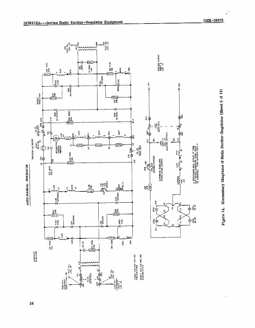
AUTO
-MAN
UAL
REGU
LATO
R
TRAN
SFER
Yo
LTM
UER
43 IA
AU
TO
TEST
I 30
9
A2CA
1x
0 30
UF
29
“F
A
DECR
EASI
NO
REP.
OU
TPUT
AT
TE
RN.
1220
CA
USES
GE
NERA
TOR
TERN
. VO
LTS
TO
INCR
EASE
. (2
””
DEFL
ECTS
LE
FT.)
Figu
re
14.
Elem
enta
ry
Dia
gram
s of
Sta
tic E
xcite
r-Reg
ulat
or
(She
et 5
of
11)
l
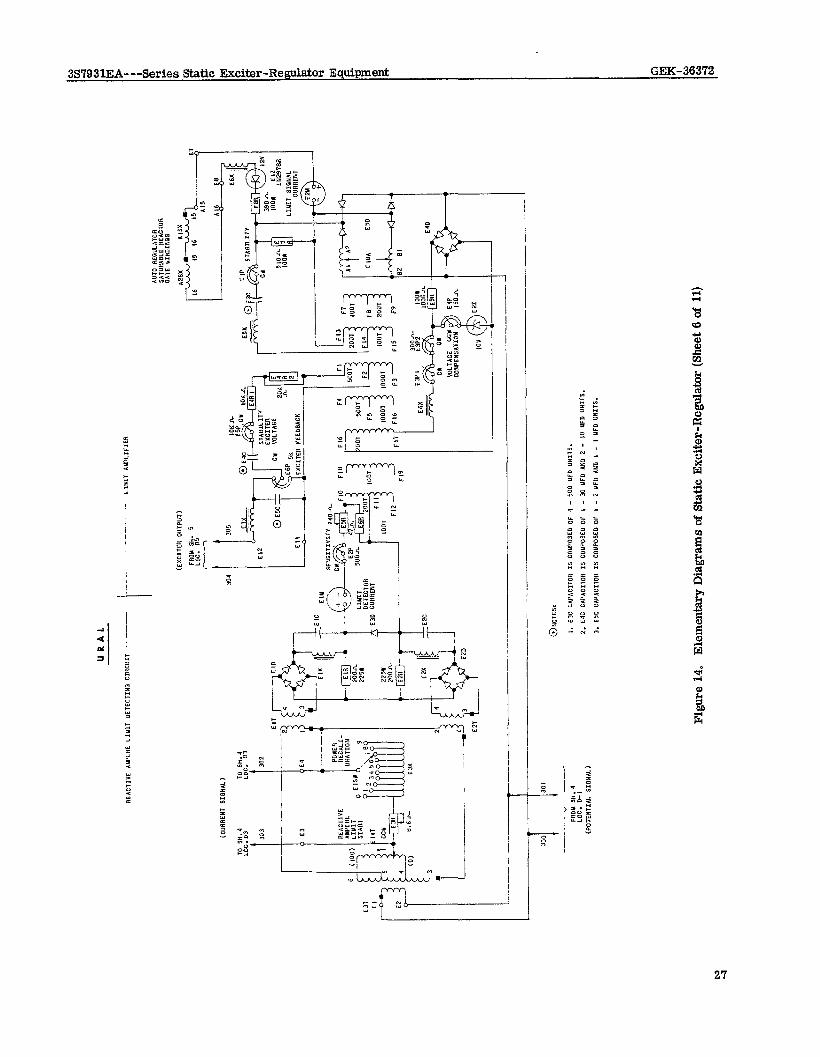
URAL
REAC
TIVE
AUPC
RE LfNl
T DE
TECT
ING C
lRCU
lT -
- ---
-
1
------
---
LINI
T AN
PLIF
IER
(CUR
RENT
SI
GNA
L)
304
i-J4
TO
SH.4
LC
C.
D-3
(EXC
ITER
O
UTPU
T)
FRON
SH
. 5
LOC.
05
r-
--l \
A
Em Ilt
LIM
IT
SIGN
AL
CURR
ENT
-~-_
___
--___
~ -
--.-
-~ “---
- FR
OM S”
. 4
I. E3
C CA
PACI
TOR
IS
COUP
OSED
O
F 4
- 50
0 UF
O
“NIT
S.
LOC.
0-
I W
’OTE
NTIA
L SI
GNA
L)
2.
E4C
CAP.
,Cm,
R IS
CO
NPOS
ED
OF
, -
30
UFD
AND
2 -
IO
UFD
UNIT
S.
3.
E5C
CAPA
CITC
R IS
CO
MPO
SED
OF
, -
2 UF
D AN
D I
- I
YFD
UNIT
S.
Figu
re
14.
Elem
enta
ry
Dia
gram
s of
Sta
tic
Exci
ter-R
egtia
tor
(She
et 6
of
11)
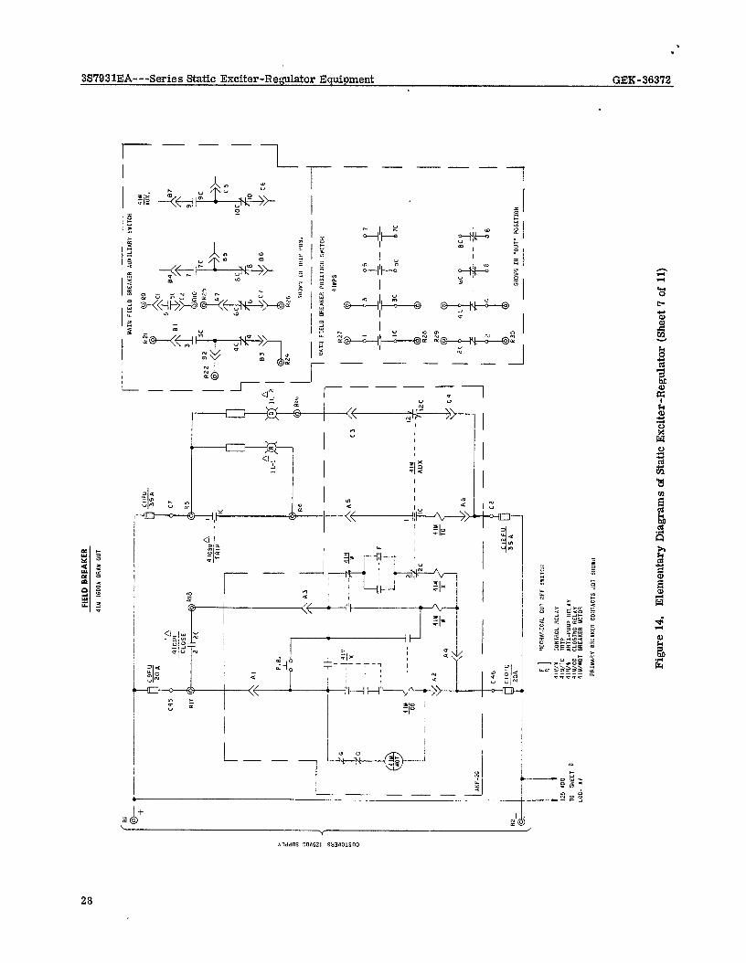
FIEL
D BR
EAKE
R
4111
16OO
A DRl
l OU
T
--__-
-- r
-~ -
I
4 IC
Srr~
TR
lP--
1
2.!4
1?
cc --I
-----
I---
I2
7 -
Ir*
----
-_
AU
X f
1 IZ
C
Figu
re
14.
Elem
enta
ry
Dia
gram
s of
Sta
tic E
xcite
r-Reg
ulat
or
(She
et 7
of
11)
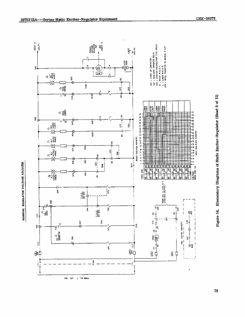
MAN
UAL
REGU
LATO
R VO
LTAG
E AD
JUST
ER
CT”
gA---
IIS
6
?-
.---C
l T- I I I I I I I I I I ClS
W
I I I I I I J 4-
---G
A 13
43
ST
ART-
UP
IRC
SC
T.O
.0.
TnEE
----i(
)- 1 I I
----,
1 I 1 L O
K I
LS4
NO
- - - -
- _,
Cm
4
I”11 I
-----
SC,
- ST
ART U
P C
ON
TAC
TOR
TR
C -
MAN
-AU
TO TR
ANSF
ER RE
LAY
ov
x -
EXC
lTER
OYE
R”O
LTPi
CE TI
ME
DE
LAY
R
- R
AlS
E M
.O.Y
.A.
L -
LOW
ER M
.O.Y
.A.
ATR
- *“
IO.
TRAN
SFER
TO Y
ANU
N. R
ELA
Y
Figu
re
14.
Elem
enta
ry
Dia
gram
s of
Sta
tic
Exci
ter-R
egul
ator
(S
heet
8 o
f 11
)
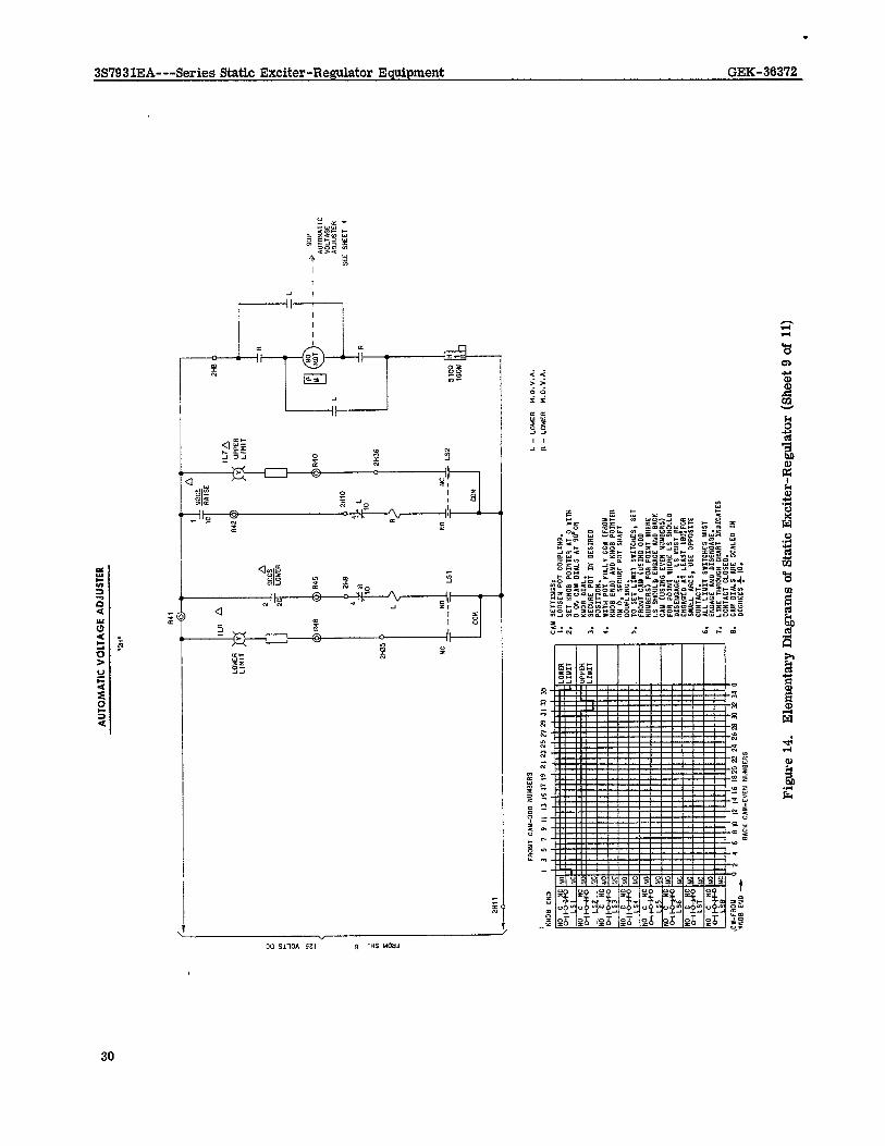
AUTO
MAT
IC
VOLT
AGE
ADJU
STER
CA”
I. 2. 3.
4.
5.
6.
7.
8.
SETT
IMDS
, LO
OSE
N Pm
CO
UPLI
NG.
A 9o
cs
z-i%
I I
2",0
0'
NC
_--_
.
CO"
___-
--
mn
:
R
Q
L
III 5
00
MO,
----
--
L
:-I
R I :.%
‘: R
i”
SET
KNUB
PO
INTE
R AT
0
WIT
H 0
ON
CAM
DI
ALS
AT
so*o
a KN
OB
DIAL
. SE
CURE
PO
, IN
DE
SIRE
D PO
SITI
ON.
WIT
H PO
T FU
LL”
CCW
(F
ROM
KN
OB
END)
AN
S KN
OB
POIN
TER
ON
0,
SECU
RE
PUT
SHAF
T 0O
”PLI
NO.
TO
SE,
U”fT
SW
ITCH
ES,
SET
FRON
T CA
N (U
SING
OD
D NU
WER
S)
FOR
POIN
T W
HERE
LS
SH
OULD
EN
DAGE
AN
D BA
CK
CAM
(U
SING
EY
EN
NUUS
ERS)
FO
R PO
INT
‘IHER
E LS
SH
OULD
DI
SENC
ACE.
LS
M
UST
BE
ENOI
OED
&T
LEAS
T IB
U.FO
R SW
ALL
IRCS
, “S
E OP
POSI
,E
CONT
ACT.
AL
L LIU
, S,
rlCHE
S M
UST
ENOl
OE
AN0
DISE
NOAO
E.
LINE
TH
ROUG
H CH
ART
XNSI
CAfE
S CO
NTAC
T CL
OSED
. CA
N DI
ALS
ARE
SCAL
ES
IN
DEGR
EES
f IO
.
I. -
LOW
ER
M.O
.V.A
.
R -
LOW
ER
M.O
.V.A
.
Figu
re
14.
Elem
enta
ry
Dia
gram
s of
Sta
tic E
xcite
r-Reg
ulat
or
(She
et 9
of
11)
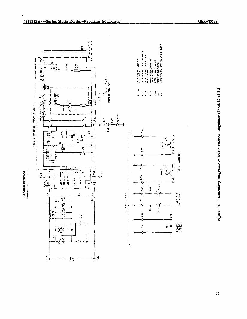
GROU
ND
DETE
CTOR
----
TO
SH3W
lC
AI
-I
EXCI
TER
OUTP
UT
----
- -^
” ‘“,
(37
SCI
543
, LO
C A-
3
I-----
- (S
UPPR
ESSO
R CK
T.)
c3e R-
GND
208
I
64F-
TS
FIEL
D OR
DUN
DETE
CTOR
TE
ST
WIT
CH
64FI
Fl
ELO
OR
OUND
DE
TECT
ION
RELA
Y
64F2
FI
ELD
ORD”
ND
DETE
CTOR
TI
YE
DELA
Y 0
SEC)
64F3
FI
ELD
GROU
ND
DETE
CTOR
LA
TCHE
G RE
LlY
I.53
0”Bl
U.E
LIG
HT
SYIT
CH
SOI
STAA
T UP
cO
NT*C
,OR
ATR
l”,OU
ATIC
TR
ANSF
ER
TO
UANU
AL
RELA
Y
Figu
re
14,
Elem
enta
ry
Dia
gram
s of
Sta
tic
Exci
ter-R
egul
ator
(S
heet
10
of 1
1)
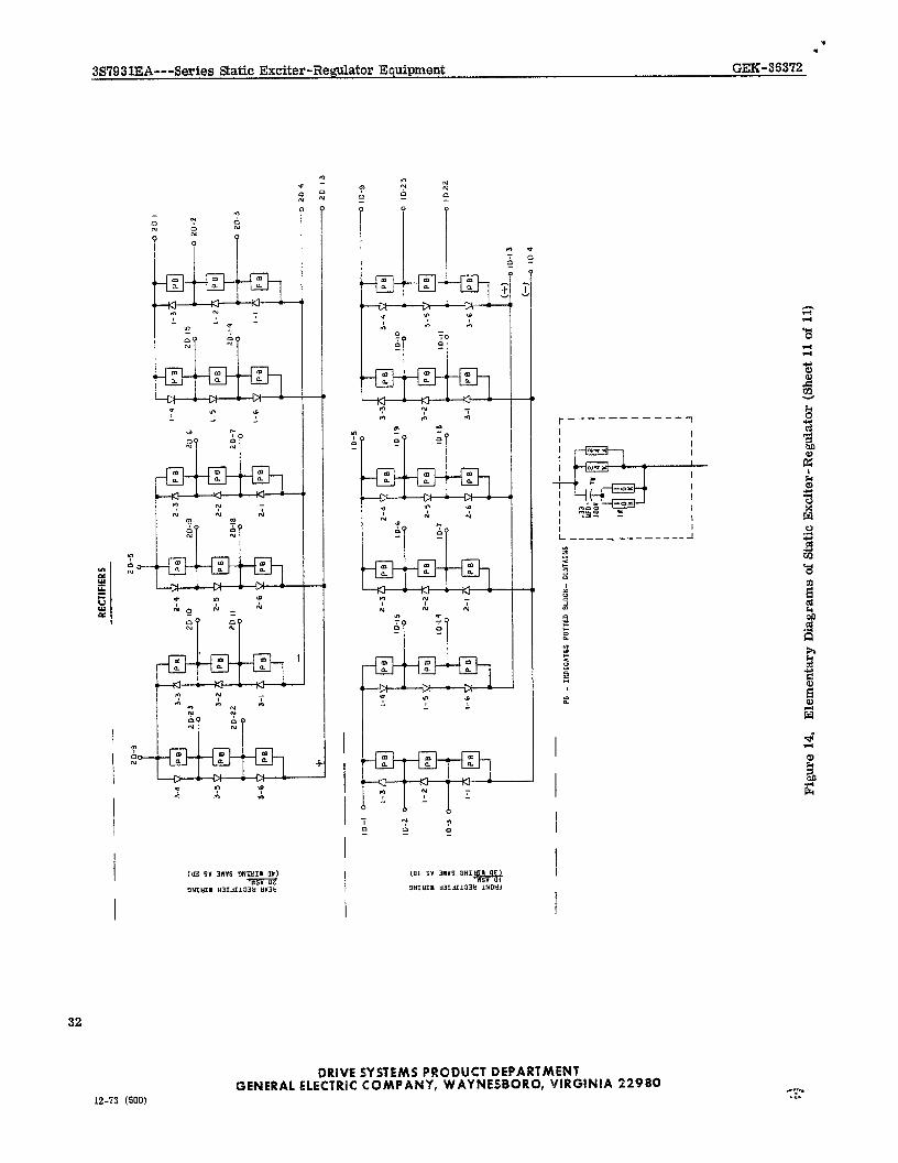
RECT
IFIE
RS
3-6 I-3
Pa
‘-2 PB
3
- l-1 PB
1-4 #I
PB
1-6
- --
--
PS
- IN
DlOA
TES
POTT
ED
BLO
CK-
CONT
AINS
I--
-- --
------
-I
1 ;::
J ,o
ov
7s
; :
J I$
;
~@r
I
Lee.
----
---
J
Figu
re
14.
Elem
enta
ry
Dia
gram
s of
Sta
tic E
xcite
r-Reg
ulat
or
(She
et 1
1 of
11)