Embed Size (px)
Citation preview
Static inelastic analysis of steelframes with flexible connections
M. Sekulovic ∗ M. Nefovska–Danilovic †
Theoret. Appl. Mech., Vol.31, No.2, pp.101–134, Belgrade 2004
Abstract
The effects of connection flexibility and material yielding on the be-havior of plane steel frames subjected to static (monotonic) loads arepresented in this paper. Two types of material nonlinearities are con-sidered: flexible nodal connections and material yielding, as well asgeometric nonlinearity of the structure. To account for material yield-ing, a plastic hinge concept is adopted. A flexible connection is ide-alized by nonlinear rotational spring. Plastic hinge is also idealizedby nonlinear rotational spring attached in series with the rotationalspring that accounts for connection flexibility. The stiffness matrixfor the beam with flexible connections and plastic hinges at its endsis obtained. To illustrate the validity and accuracy of the proposednumerical model, several examples have been conducted.
Keywords: steel frame, flexible connections, plastic hinge, nonlinearanalysis
∗Faculty of Civil Engineering, University of Belgrade, Bulevar kralja Aleksandra73, 11000 Belgrade, Serbia, email: [email protected]
†Faculty of Civil Engineering, University of Belgrade, Bulevar kralja Aleksandra73, 11000 Belgrade, Serbia, email: [email protected]
101
102 M. Sekulovic, M. Nefovska–Danilovic
Nomenclature
B, T, t, D Section’s dimensions: flange width, flange thickness,web thickness, depth of section
E Young’s modulus of elasticityF External force vectorF Cross–sectional areaG Correction matrixI Section’s moment of inertiakII Stiffness matrix of beam element with rigid connections
according to the second order theoryK System stiffness matrixkci Stiffness of rotational spring that accounts for flexible
nodal connectionsksi Stiffness of rotational spring that accounts for material
yieldingki Stiffness of resulting rotational springkco Initial connection stiffnessl Length of beam elementM MomentMy Yielding momentMp Plastic moment capacity of cross–sectionMpr Reduced plastic moment of cross–section due to
presence of axial forceMu Ultimate moment of nonlinear flexible connectionN Axial forceq Displacement vectorU Potential energy of beam elementv(x) Lateral displacement of beam elementWy Elastic modulusσr Maximal residual stressσy Yielding stressφ′i, φ
∗i End rotations of internal nodes of beam element
φi End rotations of structural nodes of the frameθci Additional rotation due to connection flexibilityθsi Additional rotation due to plastic hinge
Static inelastic analysis of steel frames... 103
1 Introduction
In the analysis and design of steel frame structures the assumptions oftotally rigid or ideally pinned nodal connections are commonly used, aswell as the assumption of linear elastic behavior of the material. Numer-ous experimental investigations on beam-to-column connections due tostatic (monotonic) loads have shown that nodal connections exhibit non-linear behavior in the whole load domain for all types of connections [1].When the structure is subjected to loads that exceed the proportionallimit of the material, the material starts to yield, thus the above men-tioned assumptions become inadequate and cannot represent the realbehavior of the structure. In this case plastic analysis is required. Con-nection flexibility, material yielding and the effects of geometrical non-linearities are major parameters that control the load-carrying capacityof the structure, and have become a part of many national Standardsand Codes (Eurocode3, AISC, British Standards, etc). Moreover, fast-speed personal computers developed in the last 20 years made the useof nonlinear analysis procedures more available for practical purposes.
Plastic analysis methods can be classified in two groups: distributedplasticity methods that account for spreading of plastic zones within thewhole volume of the structure (Plastic zone methods) and lumped plas-ticity methods that assume plastic zones to be formed within small areasat the ends of frame members called plastic hinges, while frame membersexhibit elastic behavior between plastic hinges (Plastic hinge methods).Plastic designs based on the plastic zone methods require discretizationof structure into many members as well as subdivision of cross-sectionsinto longitudinal and transverse fibers in order to control formation ofplastic zones. The effects of residual stresses and material strain hard-ening can be taken into account in the plastic zone method. Plastic zonemethods are more general and require definition of stress-strain relation-ship for internal forces computations. They are also more accurate thanthe Plastic hinge methods, but require huge computational effort.
Analysis and designs based on Plastic hinge methods assume themember cross–section is ideally elastic until the full plastic capacity ofthe cross–section is reached, when the cross–section becomes perfectlyplastic, i.e. plastic hinge is formed. In this case the effects of resid-ual stresses and material hardening cannot be accountered for in the
104 M. Sekulovic, M. Nefovska–Danilovic
analysis. Al-Mashary and Chen [2], Yau and Chan [3], Chen and Chan[4] and Chan and Chui [5] improved the elastic–perfectly plastic hingemodel in order to account for the gradual plastificitation of cross–sectionby modeling the plastic hinges at elements ends with zero-length rota-tional springs. Moreover, Chan and Chui [5] analyzed combined effectof connection flexibility and material yielding on the response of steelframes using springs in-series at elements ends. Plastic hinge methodsare based on the force-deformation relationships derived from the cor-responding stress-strain relationships in order to monitor cross-sectionplastification, i.e. formation of plastic hinges at elements ends. Theyrequire less input data and less computational time comparing with thePlastic zone methods, which make them convenient for practical designof frame structures.
Beside these computer based plastic hinge methods of inelastic struc-tural analysis, a method of limit load capacity exists. It has been widelyused 50 years ago in order to analyze structures without computer cal-culations. Since this paper deals with computer based plastic hingemethods, this method will not be analyzed and described herein.
This paper presents an extension of previous author’s work [6]–[12]regarding static and dynamic analysis of flexible connected steel frames,on elastic-plastic analysis based on plastic hinge concept. Beside nonlin-ear behavior of nodal connections, a material yielding is also consideredthrough formation of plastic hinges at elements ends. So, all materialnonlinearities are lumped at elements ends, while the regions betweenplastic hinges are assumed to behave elastically. These two types ofmaterial nonlinearities are interactive with the geometrical nonlinearityof the structure.
Flexible nodal connections and material yielding are modeled by us-ing rotational springs at element ends attached in series, [3], [5]. Todescribe a nonlinear behavior of flexible nodal connections, a three pa-rameter model proposed by Richard and Abbot [13] is used. A sectionassemblage concept [14] is used for determination of moment–axial forcefull yield interaction diagrams for a cross-section. Two types of plasticmodels are analyzed: elastic–perfectly plastic model, and elastic–plasticmodel that accounts for gradual plastification of cross–section.
The stiffness matrix is obtained based on the governing differentialequations of second–order theory, so each beam represents one frame
Static inelastic analysis of steel frames... 105
element. Nodal displacements and rotations are chosen as the primaryunknowns, while displacements and rotations at the element ends areeliminated. Thus, the numbers of degrees of freedom are the same asfor the system with rigid connections.
Based on the above mentioned theoretical considerations, previouslydeveloped computer program is modified and extended to elastic–plasticanalysis of plane steel frames with flexible connections. A parametricstudy is carried out to show the influence of joint flexibility and materialyielding on load–carrying capacity of the structure.
2 Cross–Section Strength
When the structure is subjected to load that exceeds the proportionallimit of the material, a yielding occurs in the most loaded cross–sectionof the structure. Material yielding significantly reduces moment capacityof the cross-section, as well as the load carrying capacity of the wholestructure.
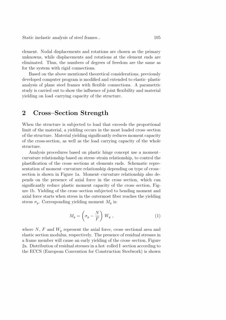
Analysis procedures based on plastic hinge concept use a moment–curvature relationship based on stress–strain relationship, to control theplastification of the cross–sections at elements ends. Schematic repre-sentation of moment–curvature relationship depending on type of cross–section is shown in Figure 1a. Moment–curvature relationship also de-pends on the presence of axial force in the cross–section, which cansignificantly reduce plastic moment capacity of the cross–section, Fig-ure 1b. Yielding of the cross–section subjected to bending moment andaxial force starts when stress in the outermost fiber reaches the yieldingstress σy. Corresponding yielding moment My is:
My =
(σy − N
F
)Wy , (1)
where N , F and Wy represent the axial force, cross–sectional area andelastic section modulus, respectively. The presence of residual stresses ina frame member will cause an early yielding of the cross–section, Figure2a. Distribution of residual stresses in a hot–rolled I–section according tothe ECCS (European Convention for Construction Steelwork) is shown

106 M. Sekulovic, M. Nefovska–Danilovic
Figure 1: Schematic moment–curvature relationship: a) depending ontype of cross–section, b) depending on the magnitude of axial force
in Figure 2b. In this case, yielding moment My is:
My =
(σy − σr − N
F
)Wy , (2)
where σr is residual stress.
2.1 Section assemblage method
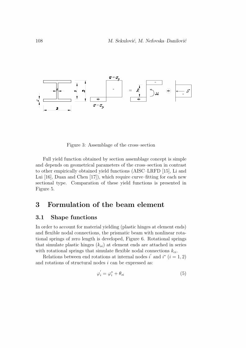
Chan and Chui [14] developed an efficient method for determination ofplastic moment capacity of cross–section in the presence of axial force,called section assemblage method, which is convenient to be used for I–shaped cross–sections. In this method it is assumed that the web of thesection takes the axial force, while the remaining portion of the sectionresists the bending moment, Figure 3.
When the neutral axis is in the web (zo ≤ d/2), the half–depth ofplastic zone in the section and section moment resistance by the re-
Static inelastic analysis of steel frames... 107
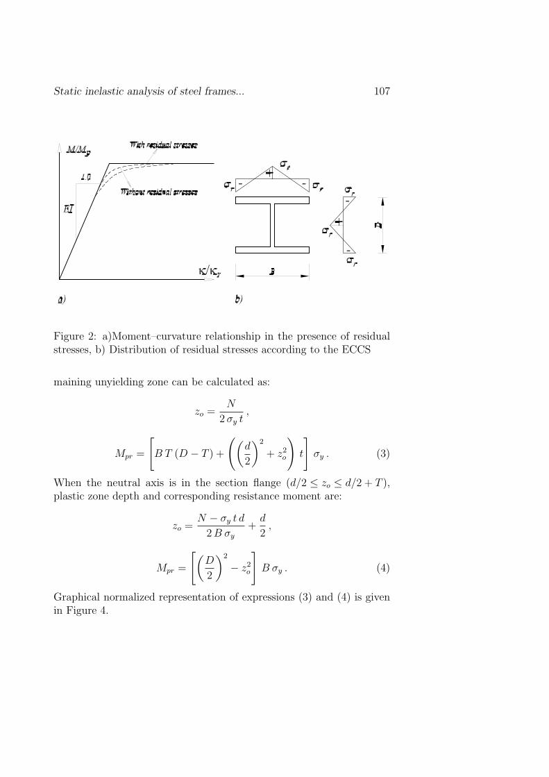
Figure 2: a)Moment–curvature relationship in the presence of residualstresses, b) Distribution of residual stresses according to the ECCS
maining unyielding zone can be calculated as:
zo =N
2 σy t,
Mpr =
[B T (D − T ) +
((d
2
)2
+ z2o
)t
]σy . (3)
When the neutral axis is in the section flange (d/2 ≤ zo ≤ d/2 + T ),plastic zone depth and corresponding resistance moment are:
zo =N − σy t d
2 B σy
+d
2,
Mpr =
[(D
2
)2
− z2o
]B σy . (4)
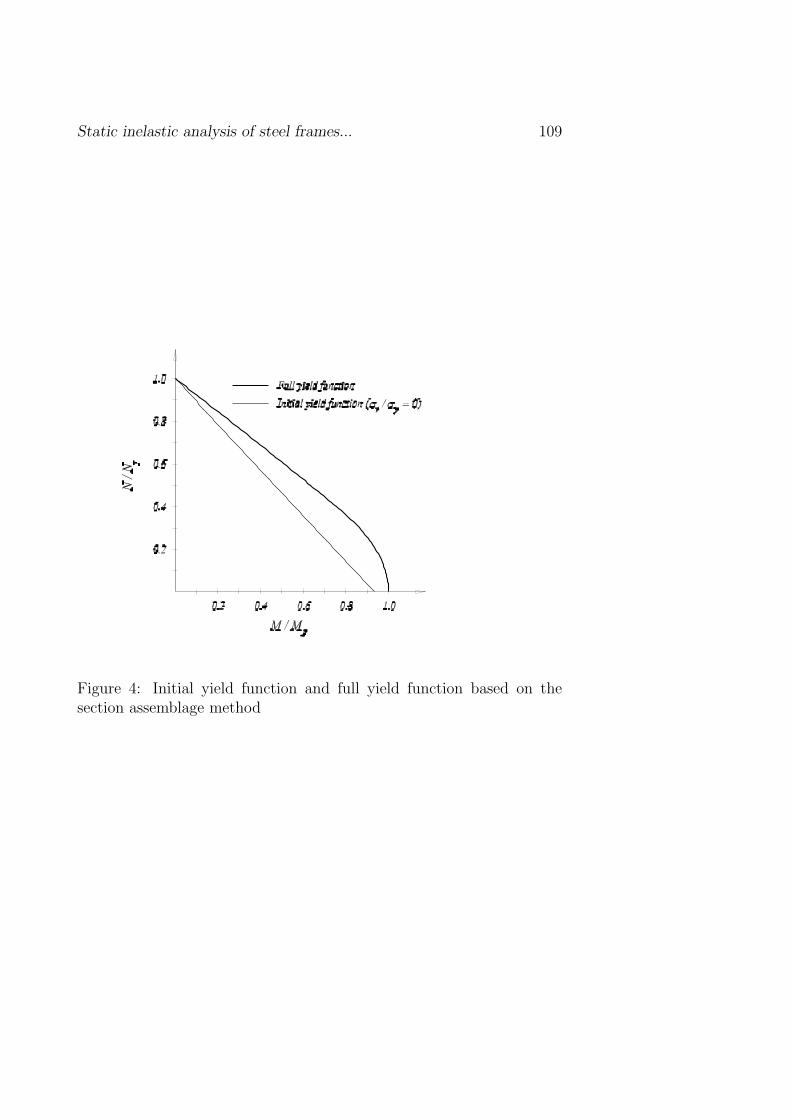
Graphical normalized representation of expressions (3) and (4) is givenin Figure 4.
108 M. Sekulovic, M. Nefovska–Danilovic
Figure 3: Assemblage of the cross–section
Full yield function obtained by section assemblage concept is simpleand depends on geometrical parameters of the cross–section in contrastto other empirically obtained yield functions (AISC–LRFD [15], Li andLui [16], Duan and Chen [17]), which require curve–fitting for each newsectional type. Comparation of these yield functions is presented inFigure 5.
3 Formulation of the beam element
3.1 Shape functions
In order to account for material yielding (plastic hinges at element ends)and flexible nodal connections, the prismatic beam with nonlinear rota-tional springs of zero length is developed, Figure 6. Rotational springsthat simulate plastic hinges (ksi) at element ends are attached in serieswith rotational springs that simulate flexible nodal connections kci.
Relations between end rotations at internal nodes i′and i∗ (i = 1, 2)
and rotations of structural nodes i can be expressed as:
ϕ′i = ϕ∗i + θsi (5)
Static inelastic analysis of steel frames... 109
Figure 4: Initial yield function and full yield function based on thesection assemblage method

110 M. Sekulovic, M. Nefovska–Danilovic
Figure 5: Comparation of different full yield functions

Static inelastic analysis of steel frames... 111
Figure 6: A frame element with flexible connections and plastic hinges
ϕi = ϕ′i + θci , i = 1,2 , (6)
where θci are additional rotations due to joint flexibility and θsi areadditional rotations due to plastic hinges. Rotations θci and θsi dependon spring stiffnesses kci and ksi respectively:
θc =
0θc1
0θc2
=
0M∗
1
kc1
0M∗
2
kc2
, θs =
0θs1
0θs2
=
0M∗
1
ks1
0M∗
2
ks2
, (7)
where M∗1 and M∗
2 are bending moments at ends of the beam.
Force–displacement relation according to the second–order theorycan be written as [7]:
T ∗1
M∗1
T ∗2
M∗2
=
EI
l3
12 φ1 6 l φ2 −12 φ1 6 l φ2
4 l2 φ3 −6 l φ2 2 l2 φ4
12 φ1 −6 l φ2
simetr. 4 l2 φ3
v∗1ϕ∗1v∗2ϕ∗2
= KII q∗ , (8)
112 M. Sekulovic, M. Nefovska–Danilovic
where φi, i = 1, 2, 3, 4 are correction trigonometric or hyperbolic func-tions depending on the axial force in the frame element (compressive ortensile). These correction functions can be find in Reference [18].
According to expressions (5), (6), (7) and (8), end moments M∗1 and
M∗2 can be written as:
[M∗
1
M∗2
]=
EI
l2
[6 φ2 4l φ3 −6 φ2 2l φ4
6 φ2 2l φ4 −6 φ2 4l φ3
]
v1
ϕ1 − (θs1 + θc1)v2
ϕ′2 − (θs2 + θc2)
=
=EI
l2
[6 φ2 4l φ3 −6 φ2 2l φ4
6 φ2 2l φ4 −6 φ2 4l φ3
](q− θs − θc) (9)
Substituting expressions (7) into expression (9), leads to:
[M∗
1
M∗2
]=
EI
∆l2
[1 + 4 g2 φ3 −2 g2 φ4
−2 g1 φ4 1 + 4 g1 φ3
]× (10)
×[
6 φ2 4l φ3 −6 φ2 2l φ4
6 φ2 2l φ4 −6 φ2 4l φ3
]q ,
where∆ = (1 + 4 g1 φ3) (1 + 4 g2 φ3)− 4 g1 g2 φ4
2 ,
1
ks1
+1
kc1
=1
k1
,
1
ks2
+1
kc2
=1
k2
,
gi =EI
ki
i = 1,2 .
ki is stiffness of the resulting spring obtained by attaching the springs kci
and ksi in series. Now, the vector of total additional rotations θ = θs+θc
can be written as:
θ =
0θ1
0θ2
=
0M∗
1
k1
0M∗
2
k2
= Gq , (11)
Static inelastic analysis of steel frames... 113
where G is corrective matrix of the frame element that accounts for jointflexibility and plastic hinges at element ends according to the second–order theory:
G =1
∆
0 0 0 0g21 g22 g23 g24
0 0 0 0g41 g42 g43 g44
. (12)
The nonzero elements of the correction matrix are:
g21 = −g23 =6
l[g1 + 2 g1 g2 (2 φ3 − φ4)]
g22 = 4[g1 φ3 + g1 g2 (4 (φ3)
2 − (φ4)2)
]
g24 = 2 g1 φ4
g41 = −g43 =6
l[g2 + 2 g1 g2 (2 φ3 − φ2)]
g42 = 2 g2 φ4
g44 = 4[g2 φ3 + g1 g2 (4 (φ3)
2 − (φ4)2)
].
Lateral displacement v(x) of the beam with flexible nodal connectionsand plastic hinges at element ends taking into account expression (11)can be written as:
v(x) = N(x)q∗ = N(x)(q− (θs + θc)) = N(x)(q− θ) =
= N(x)(I−G)q = N(x)q , (13)
where N(x) is vector of interpolation functions of the prismatic beambased on the analytical solutions of the second–order analysis [6], andN(x) is vector of interpolation functions of the frame element with flex-ible connections and plastic hinges.
3.2 Stiffness matrix
The flexural stiffness matrix of the proposed beam can be obtained fromthe total potential energy of the element, which can be written as:
U =EI
2
∫ l
0
[v′′(x)]2 dx +
1
2
(2∑
i=1
ki θ2i
), (14)

114 M. Sekulovic, M. Nefovska–Danilovic
The first term in the above expression is the potential energy of theframe element, and the second term represents the potential energy ofthe resulting springs at element ends. After substituting expression (13)into (14), the total potential energy can be written in the following form:
U =1
2qT
[EI (I−G)T
(∫ l
0
[N(x)T ]′′[N(x)]
′′dx
)(I−G) + GT SG
]q ,
(15)where
S =
0 0 0 00 k1 0 00 0 0 00 0 0 k2
, ki =
ksi kci
ksi + kci
, i = 1, 2 ,
θ = θs + θc .
Expression (15) can be written in the other form as:
U =1
2qT (kII + kef + ks)q , (16)
where matrices kII , kef and ks are defined as:
kII = EI
∫ l
0
[N(x)T ]′′[N(x)]
′′dx , (17)
kef = −GT kII + kII G + GT kII G , (18)
ks = GT SG , (19)
denoting beam stiffness matrix with the rigid connections according tothe second–order theory and correction matrices that accounts for theeffects of joint flexibility and material yielding respectively.
The elements of flexural matrix k are:
k11 = −k13 = k33 =12EI
l3 ∆(1 + g1 + g2)
k12 = −k23 =6EI
l2 ∆(1 + 2 g2)
k14 = −k34 =6EI
l2 ∆(1 + 2 g1)
Static inelastic analysis of steel frames... 115
k22 =4EI
l ∆(1 + 3 g2)
k24 =2EI
l ∆
k44 =4EI
l ∆(1 + 3 g1) .
In the case of the beam with flexible connections and without plastichinges at element ends (kci 6= 0, ksi → ∞), the stiffness matrix can beobtained from the above expression where:
ki = kci , i = 1, 2 gi = gci =EI
l kci
.
In the case of the beam with rigid connections and plastic hinges (ksi 6=0, kci → ∞), the stiffness matrix can be obtained from the above ex-pression where:
ki = ksi , i = 1, 2 gi = gsi =EI
l ksi
.
The relative rotations θci due to flexible nodal connections and relativerotations θsi due to plastic hinges must be calculated in order to definerotational stiffnesses kci and ksi of end springs. Based on the followingrelations:
q = q′+ θc ,
q′= q∗ + θs ,
and expression (11), relative rotations θci and θsi are:
0θc1
0θc2
=
EI
l2 ∆
0 0 0 0g′21 g
′22 g
′23 g
′24
0 0 0 0g′41 g
′42 g
′43) g
′44
v1
φ1
v2
φ2
θc = G′q , (20)
θs = (G−G′)q = G
′′q . (21)
The nonzero elements of matrix G′are:
g′21 = −g
′23 =
6
kc1
(1 + 2g2)

116 M. Sekulovic, M. Nefovska–Danilovic
g′22 =
4l
kc1
(1 + 3g2)
g′24 =
2l
kc1
g′41 = −g
′43 =
6
kc2
(1 + 2g1)
g′42 =
2l
kc2
g′44 =
4l
kc2
(1 + 3g1).
3.3 Plastic hinge modeling
3.3.1 Elastic–perfectly plastic model
This is the simplest model that accounts for material yielding, but itcannot include residual stresses and material hardening, thus it cannotrepresent real structural behavior. Two conditions of cross–section areconsidered: ideally elastic, when the plastic moment capacity has notbeen reached, and totally plastic, when the plastic moment capacity hasbeen reached. In the case when cross–section behaves as ideally elasticthe stiffness of end rotational spring that models material yielding is as-signed to be infinity (high value in order to avoid numerical difficulties).When the plastic moment is reached, plastic hinge is formed and thestiffness of rotational spring is assigned to be zero (small value), i.e.:
ksi = 1010 , for |M | < |Mpr| , ksi = 10−10 , for |M | = |Mpr| .
This method overestimates the structural strength due to abrupt changeof section from the fully elastic to totally plastic state.
3.3.2 Model that accounts for gradual plastification of cross–section
This model accounts for gradual plastification of cross–section. Whenthe yielding moment My is reached, cross–section starts to yield, and
Static inelastic analysis of steel frames... 117
stiffness of rotational spring ksi needs to be modified. Chan and Chui[5] proposed the following expression to define spring stiffness:
ks =6EI
l
Mpr −M
M −My
, for My < M < Mpr , (22)
where EI is flexural stiffness of the section, l is member length and Mpr
reduced plastic moment due to presence of axial force.Thus, the springstiffness ksi in this case varies from zero (elastic state) to infinity (plasticstate). Between these two limit states spring stiffness is calculated usingexpression (22).
3.4 Semi–rigid connection modeling
In order to model nonlinear connection behavior a three parameterpower model proposed by Richard and Abbot [13] has been adopted.Nonlinear moment–rotation relationship is defined as:
M =kcoθc(
1 +(
θc
θco
)n)1/n, (23)
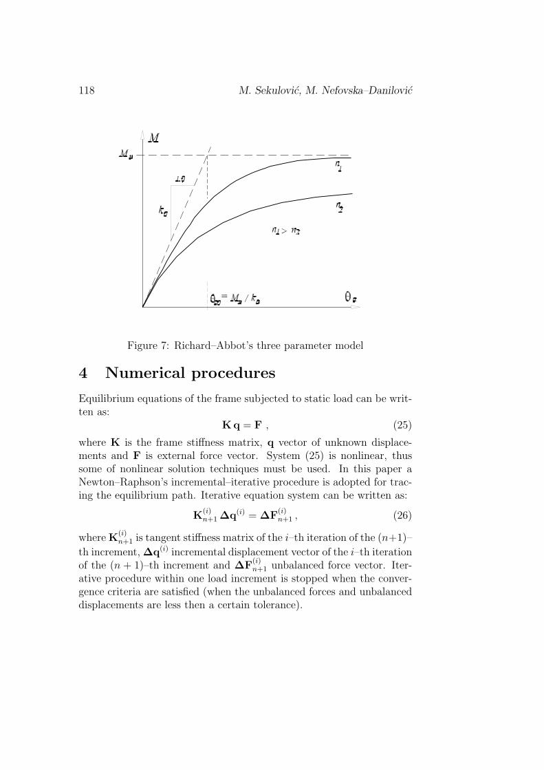
where kco is initial stiffness of the connection, θco = Mu/kco referenceconnection plastic rotation, Mu ultimate moment capacity and n shapeparameter. Graphical representation of three parameter model is pre-sented in Figure 7.
Values of these three parameters are usually determined from em-pirical expressions that depend on the type of the connection, Kishi etal.[19]. Spring stiffness kc that models nonlinear connection behavior isdefined as the tangent slope of the M − θc curve defined by expression(23):
dM
dθc
= kc =kco[
1 +(
θc
θco
)n] 1n
+1. (24)
This value decreases as moment of the connection increases and variesfrom kco to zero when M = Mu.
118 M. Sekulovic, M. Nefovska–Danilovic
Figure 7: Richard–Abbot’s three parameter model
4 Numerical procedures
Equilibrium equations of the frame subjected to static load can be writ-ten as:
Kq = F , (25)
where K is the frame stiffness matrix, q vector of unknown displace-ments and F is external force vector. System (25) is nonlinear, thussome of nonlinear solution techniques must be used. In this paper aNewton–Raphson’s incremental–iterative procedure is adopted for trac-ing the equilibrium path. Iterative equation system can be written as:
K(i)n+1 ∆q(i) = ∆F
(i)n+1 , (26)
where K(i)n+1 is tangent stiffness matrix of the i–th iteration of the (n+1)–
th increment, ∆q(i) incremental displacement vector of the i–th iterationof the (n + 1)–th increment and ∆F
(i)n+1 unbalanced force vector. Iter-
ative procedure within one load increment is stopped when the conver-gence criteria are satisfied (when the unbalanced forces and unbalanceddisplacements are less then a certain tolerance).
Static inelastic analysis of steel frames... 119
At the beginning of incremental–iterative procedure it is assumedthat all members exhibit elastic behavior (spring stiffnesses ksi are setto have a high value) and all connections behave linearly (spring stiff-nesses kci equal to a initial connection stiffness kco). Spring stiffnesseskc are updated in each iteration within a load increment and are cal-culated from equation (24). Moreover, within each load increment ayielding criterion is checked, and corresponding spring stiffness ks is re-duced. This procedure is performed until the collapse of the system isreached, which is detected by checking the positive definiteness of theframe stiffness matrix.
In the case of second–order theory equation (25) must be modifieddue to incremental formulation of numerical procedure. Equilibriumequations for two states 1 and 2 can be written in the following form:
(Ko + K1g)q1 = F1
(Ko + K2g)q2 = F2 ,
where Ko is a part of frame stiffness matrix due to first order theory, Kig
(i = 1,2) a part of frame stiffness matrix due to second order theory, Fi,(i = 1,2) nodal force vectors. After a subtraction of the above equations,the following equation is obtained:
K∆q = ∆F′, (27)
where:
K = (Ko + K2g) ,
∆F = F2 − F1 ,
∆q = q2 − q1 ,
∆F′= ∆F + (K1
g −K2g)q1 .
Vector ∆F′
contains additional part, which occurs due to change ofequilibrium configuration and setting the equilibrium conditions on thedeformed system configuration.
120 M. Sekulovic, M. Nefovska–Danilovic
5 Numerical examples
Based on the above theoretical considerations a computer program isdeveloped for nonlinear static analysis of plane steel frames. In orderto verify efficiency and accuracy of the developed computer programseveral examples analyzed by other authors have been carried out. Aparametric study has also been carried out in order to show the influenceof certain parameters on the critical load and load carrying capacity ofthe frame.
5.1 Fixed end beam
A fixed end beam subjected to concentrated vertical force in joint B,analyzed by Liew [20] and Chan [5], is presented in Figure 8.
Residual stresses reach 50% of yield stress σy, according to ECCS.Results of the analysis are presented in Figure 8 and are in good agree-ment with results obtained by Chan. The first plastic hinge has formedin joint A, the second in joint B and the third in joint C, which causedthe collapse of the beam. In the case of elastic–perfectly plastic modelload–deflection relation is polygonal line with slope change where theplastic hinge is formed, while in the case of the model with gradualplastification of cross–section this relation is smooth curve.
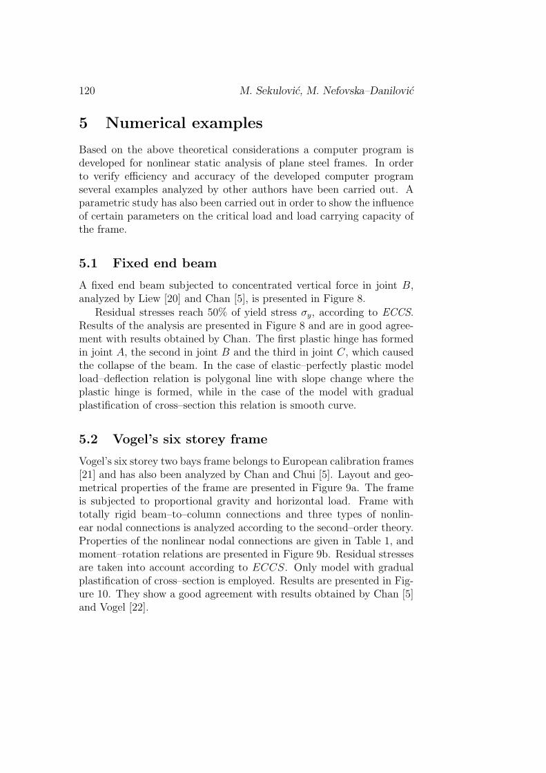
5.2 Vogel’s six storey frame
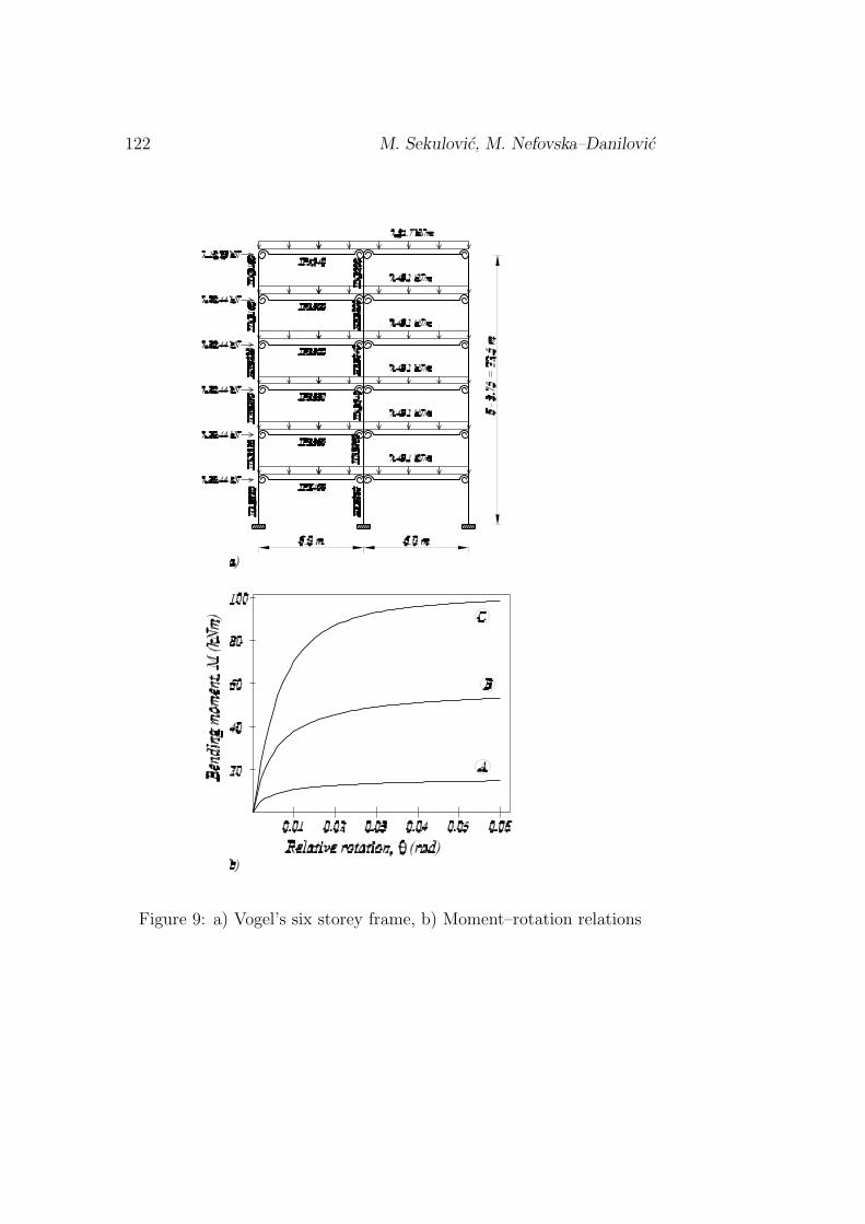
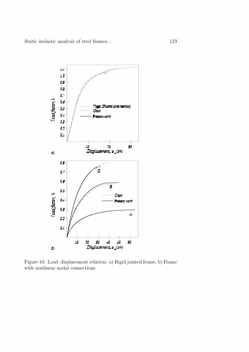
Vogel’s six storey two bays frame belongs to European calibration frames[21] and has also been analyzed by Chan and Chui [5]. Layout and geo-metrical properties of the frame are presented in Figure 9a. The frameis subjected to proportional gravity and horizontal load. Frame withtotally rigid beam–to–column connections and three types of nonlin-ear nodal connections is analyzed according to the second–order theory.Properties of the nonlinear nodal connections are given in Table 1, andmoment–rotation relations are presented in Figure 9b. Residual stressesare taken into account according to ECCS. Only model with gradualplastification of cross–section is employed. Results are presented in Fig-ure 10. They show a good agreement with results obtained by Chan [5]and Vogel [22].

Static inelastic analysis of steel frames... 121
Figure 8: Fixed end beam: Load–lateral deflection relation
122 M. Sekulovic, M. Nefovska–Danilovic
Figure 9: a) Vogel’s six storey frame, b) Moment–rotation relations
Static inelastic analysis of steel frames... 123
Figure 10: Load–displacement relation: a) Rigid jointed frame, b) Framewith nonlinear nodal connections
124 M. Sekulovic, M. Nefovska–Danilovic
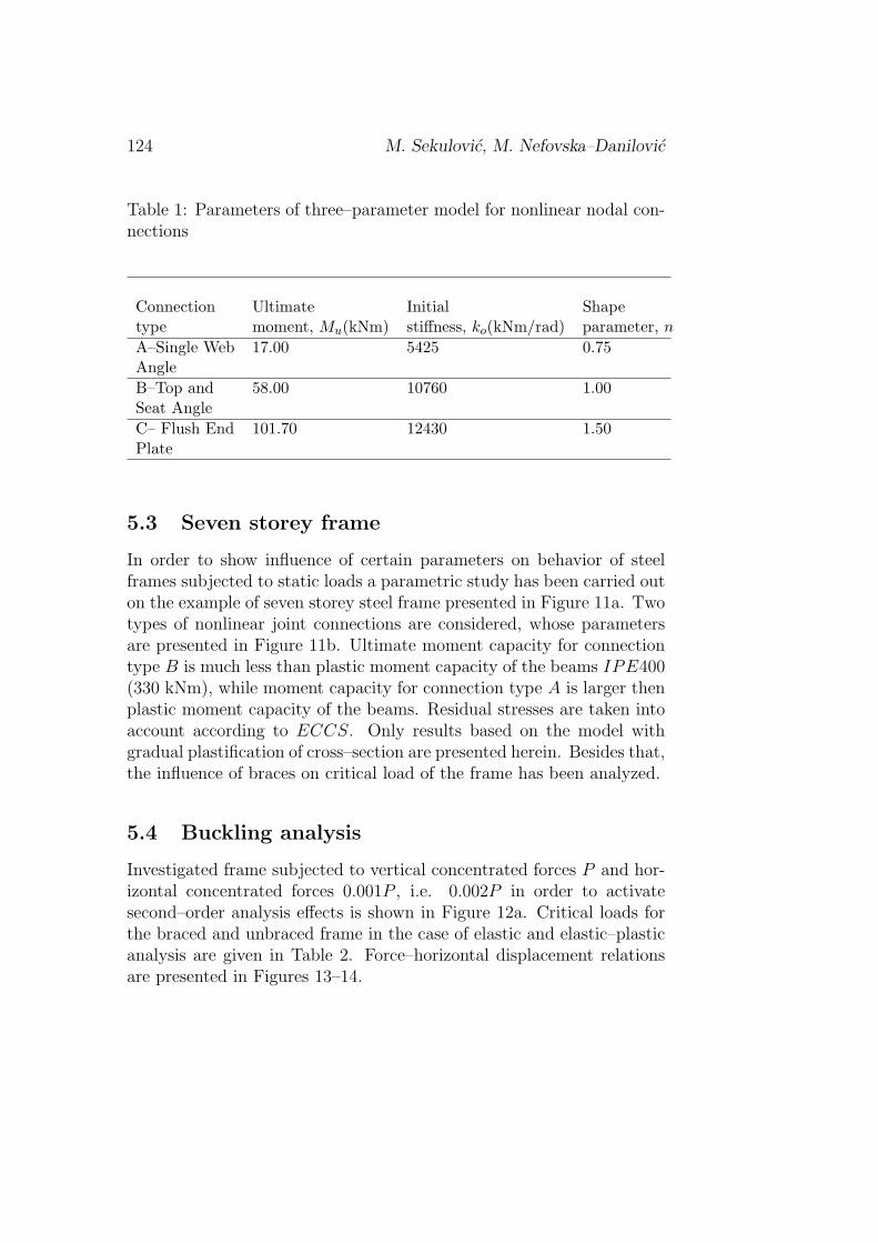
Table 1: Parameters of three–parameter model for nonlinear nodal con-nections
Connection Ultimate Initial Shapetype moment, Mu(kNm) stiffness, ko(kNm/rad) parameter, n
A–Single Web 17.00 5425 0.75AngleB–Top and 58.00 10760 1.00Seat AngleC– Flush End 101.70 12430 1.50Plate
5.3 Seven storey frame
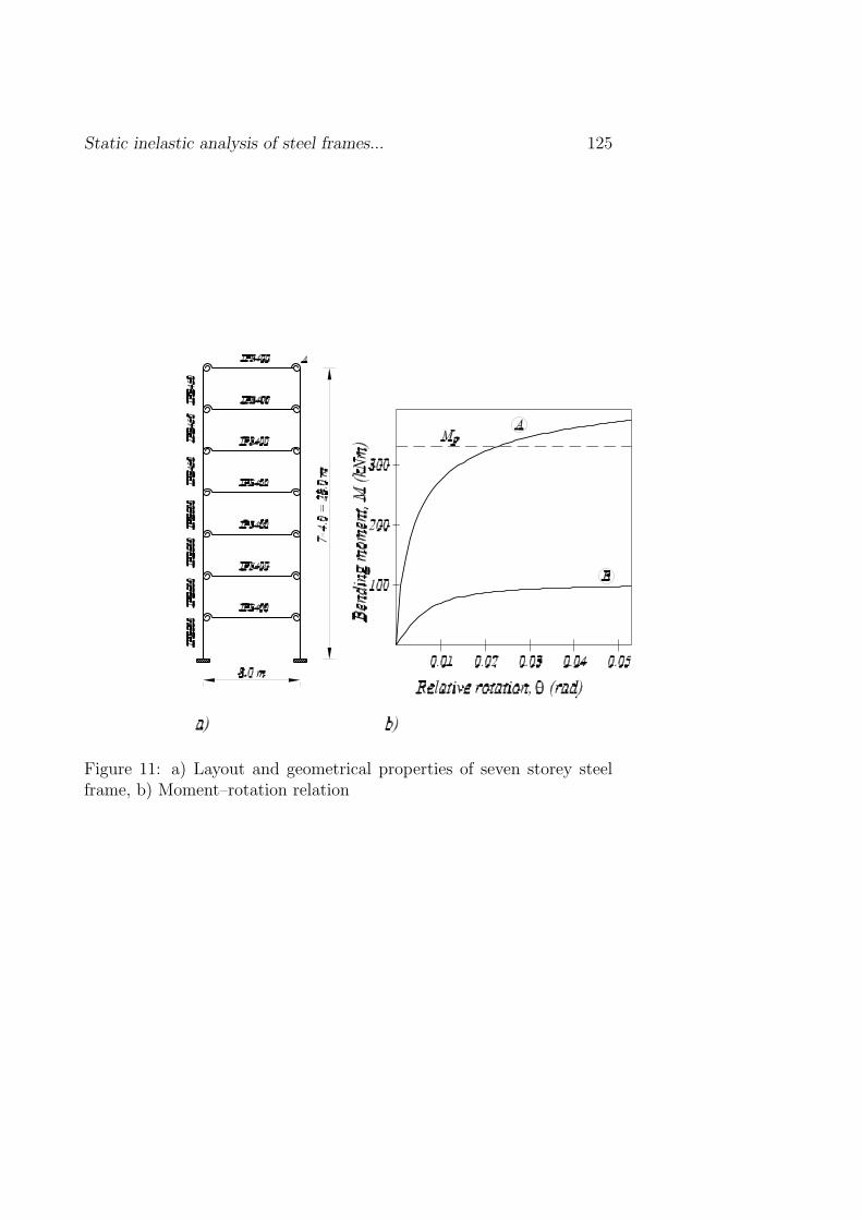
In order to show influence of certain parameters on behavior of steelframes subjected to static loads a parametric study has been carried outon the example of seven storey steel frame presented in Figure 11a. Twotypes of nonlinear joint connections are considered, whose parametersare presented in Figure 11b. Ultimate moment capacity for connectiontype B is much less than plastic moment capacity of the beams IPE400(330 kNm), while moment capacity for connection type A is larger thenplastic moment capacity of the beams. Residual stresses are taken intoaccount according to ECCS. Only results based on the model withgradual plastification of cross–section are presented herein. Besides that,the influence of braces on critical load of the frame has been analyzed.
5.4 Buckling analysis
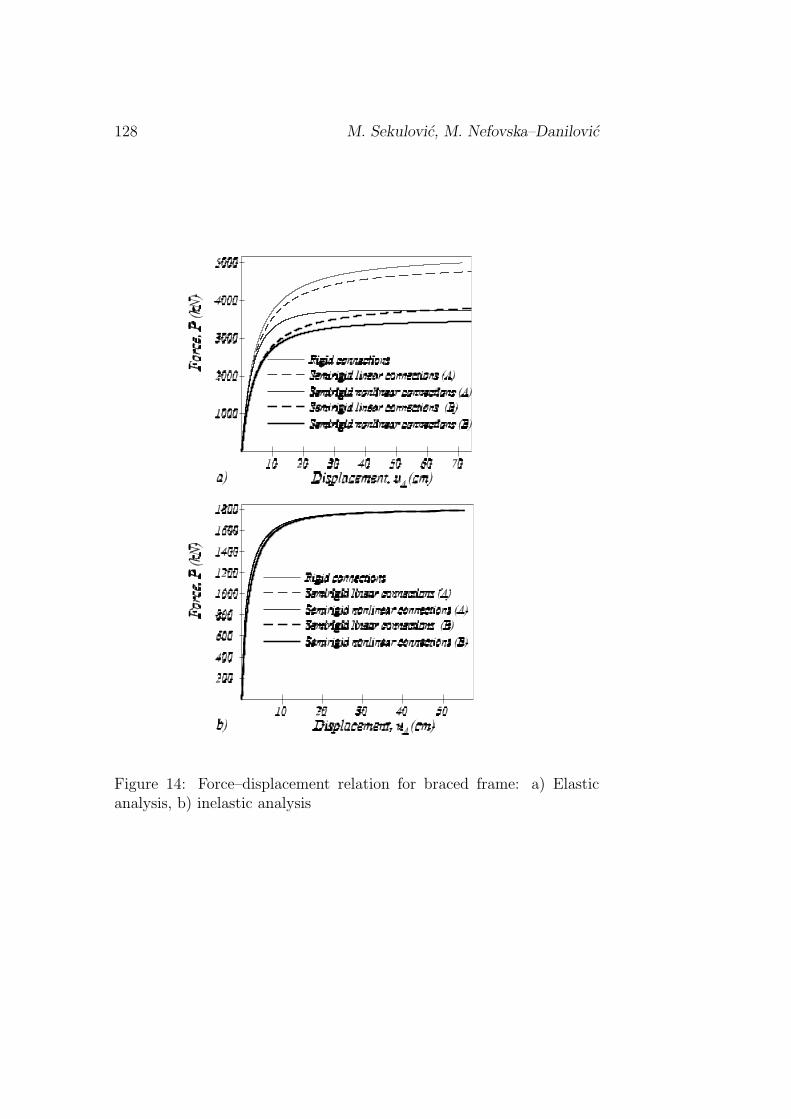
Investigated frame subjected to vertical concentrated forces P and hor-izontal concentrated forces 0.001P , i.e. 0.002P in order to activatesecond–order analysis effects is shown in Figure 12a. Critical loads forthe braced and unbraced frame in the case of elastic and elastic–plasticanalysis are given in Table 2. Force–horizontal displacement relationsare presented in Figures 13–14.
Static inelastic analysis of steel frames... 125
Figure 11: a) Layout and geometrical properties of seven storey steelframe, b) Moment–rotation relation

126 M. Sekulovic, M. Nefovska–Danilovic
Figure 12: Seven storey frame: a) Buckling analysis, b) Load–carryingcapacity analysis
In the case of elastic analysis, critical load decreases as flexibilityof nodal connections increase, which is specially expressed in the caseof unbraced frame. In the inelastic analysis, critical load is almost in-dependent on the connection flexibility (specially in the case of bracedframe). This is because the critical load is dominated by the plasticmoment capacity of the columns in the first two floors, whose plasticmoments are much less than the elastic moment capacity. Moreover,bracings significantly increase the critical load of the frame in both elas-tic and inelastic analysis. Because of that, it is more economical to usebracings in order to increase critical load of the frame, than to increasegeometrical properties of cross–sections.

Static inelastic analysis of steel frames... 127
Figure 13: Force–displacement relation for unbraced frame: a) Elasticanalysis, b) inelastic analysis
128 M. Sekulovic, M. Nefovska–Danilovic
Figure 14: Force–displacement relation for braced frame: a) Elasticanalysis, b) inelastic analysis
Static inelastic analysis of steel frames... 129
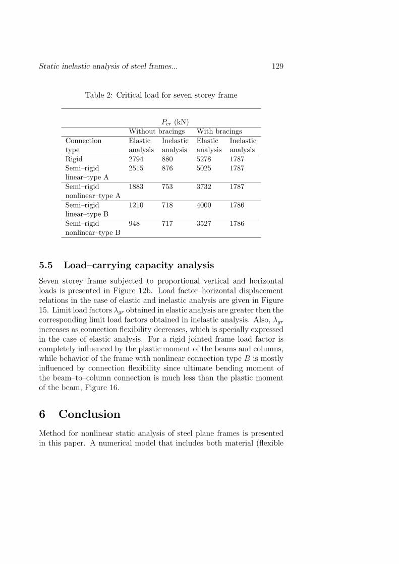
Table 2: Critical load for seven storey frame
Pcr (kN)Without bracings With bracings
Connection Elastic Inelastic Elastic Inelastictype analysis analysis analysis analysisRigid 2794 880 5278 1787Semi–rigid 2515 876 5025 1787linear–type ASemi–rigid 1883 753 3732 1787nonlinear–type ASemi–rigid 1210 718 4000 1786linear–type BSemi–rigid 948 717 3527 1786nonlinear–type B
5.5 Load–carrying capacity analysis
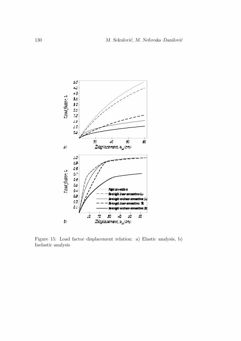
Seven storey frame subjected to proportional vertical and horizontalloads is presented in Figure 12b. Load factor–horizontal displacementrelations in the case of elastic and inelastic analysis are given in Figure15. Limit load factors λgr obtained in elastic analysis are greater then thecorresponding limit load factors obtained in inelastic analysis. Also, λgr
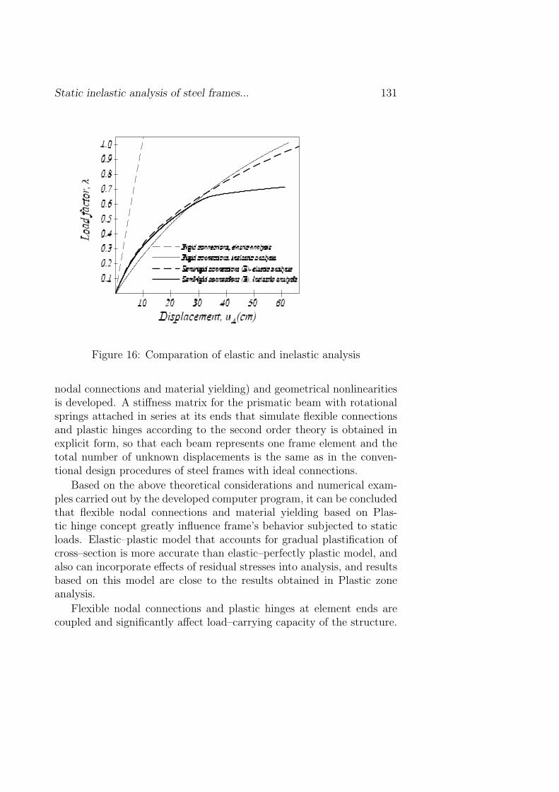
increases as connection flexibility decreases, which is specially expressedin the case of elastic analysis. For a rigid jointed frame load factor iscompletely influenced by the plastic moment of the beams and columns,while behavior of the frame with nonlinear connection type B is mostlyinfluenced by connection flexibility since ultimate bending moment ofthe beam–to–column connection is much less than the plastic momentof the beam, Figure 16.
6 Conclusion
Method for nonlinear static analysis of steel plane frames is presentedin this paper. A numerical model that includes both material (flexible
130 M. Sekulovic, M. Nefovska–Danilovic
Figure 15: Load factor–displacement relation: a) Elastic analysis, b)Inelastic analysis
Static inelastic analysis of steel frames... 131
Figure 16: Comparation of elastic and inelastic analysis
nodal connections and material yielding) and geometrical nonlinearitiesis developed. A stiffness matrix for the prismatic beam with rotationalsprings attached in series at its ends that simulate flexible connectionsand plastic hinges according to the second order theory is obtained inexplicit form, so that each beam represents one frame element and thetotal number of unknown displacements is the same as in the conven-tional design procedures of steel frames with ideal connections.
Based on the above theoretical considerations and numerical exam-ples carried out by the developed computer program, it can be concludedthat flexible nodal connections and material yielding based on Plas-tic hinge concept greatly influence frame’s behavior subjected to staticloads. Elastic–plastic model that accounts for gradual plastification ofcross–section is more accurate than elastic–perfectly plastic model, andalso can incorporate effects of residual stresses into analysis, and resultsbased on this model are close to the results obtained in Plastic zoneanalysis.
Flexible nodal connections and plastic hinges at element ends arecoupled and significantly affect load–carrying capacity of the structure.
132 M. Sekulovic, M. Nefovska–Danilovic
The overall behavior of the structure is controlled by the larger value ofplastic moment capacity of the sections and ultimate moment capacityof the flexible nodal connections. Because of that structural behaviorcan be influenced by plastic moment/connection moment ratio, i.e. ifthe ratio is much greater than 1, structural behavior is completely con-trolled by the plastic moment capacity. If the ratio is close to 1, connec-tion flexibility and material yielding simultaneously influence structuralbehavior.
References
[1] Jones S W, Kirby PA, Nethercot DA, The analysis of frameswith semi–rigid connections, A State–of–the–Art Report, Journalof Constructional Steel Research, 1983, 3(2):2–13
[2] Al–Mashary F, Chen W F, Simplified second–order inelastic anal-ysis for steel frames, The Structural Engineer, 69(23), (1991):395–399
[3] Yau C Y, Chan S L, Inelastic and stability analysis of flexibly con-nected steel frames by springs–in–series model, Journal of Struc-tural Engineering, Asce, 120(10), (1994):2803–2820
[4] Chen W F, Chan S L, Second–order inelastic analysis of steel framesusing element with midspan and end springs, Journal of StructuralEngineering, ASCE, 121(3), (1995):530–541
[5] Chan S L, Chui P P T, Non–linear static and cyclic analysis of steelframes with semi–rigid connections, Elsevier, 2000
[6] Sekulovic M, Malcevic I., Second-order analysis of frame structures,Theoretical and Applied Mechanics, 20, (1994): 209-234
[7] Sekulovic M, Salatic R., Nonlinear analysis of frames with flexibleconnections, Computers and Structures, 79(11), (2001): 1097-1107.
[8] Sekulovic M, Salatic R., Nefovska M., Dynamic analysis offrames with flexible connections, Computers and Structures, 80,(2002):935–955;

Static inelastic analysis of steel frames... 133
[9] Sekulovic M, Salatic R., Mandic R., Nefovska M., Energy dissi-pation in steel frames with semi–rigid connections, 12th Europeanconference on earthquake engineering (Published on CD), London,2002.
[10] Salatic R., Mandic R., Nefovska M., Dynamic Analysis of Frameswith Semi–Rigid and Viscous Connections, 8th International Sym-posium Macedonian Association of Structural Engineers, Ohrid,September 30– October 2, 1999
[11] Sekulovic M., Salatic R., Mandic R., Seismic Analysis of Frameswith Semi–rigid Eccentric Connections, 12th World Conference onEarthquake Engineering, Paper No. 273 (published on CD), NewZealand, 2000
[12] Sekulovic M., Kontrola vibracija konstrukcija usled dejstvazemljotresa, Izgradnja 57, (2003): 5–21.
[13] Richard RM, Abbott BJ. Versatile elastic-plastic stress-strainformula. Journal of Engineering Mechanics Division, ASCE,101(EM4), (1975): 511-515.
[14] Chan S L, Chui P P T, A generalized design–based elasto–plasticanalysis of steel frames by section assemblage concept, Journal ofEngineering Structures, 19(8), (1997):628–636
[15] AISC: Load and Resistance Factor Design Specification for Struc-tural Steel Buildings, American Institute of Steel Construction,Chicago, 1986
[16] Li Y, Lui E M, A simplified plastic zone method for frame analysis,Microcomput. Civil Eng., 10, (1995):51–62
[17] Duan L, Chen W F, A Yield Surface Equation for Doubly Sym-metrical Sections, Structural Engineering Report CE–STR–89–19,Purdue Univ., W. Lafayette, 1989
[18] Goto Y, Chen W F, Second–order elastic analysis for frame design,Journal of Structural Engineering, ASCE, 113(ST7), (1987):1501–1519
134 M. Sekulovic, M. Nefovska–Danilovic
[19] Kishi N., Chen W.F., Data Base of Steel Beam–To–ColumnConnections, Structural Engineering Report No. CE–STR–86–26,School of Civil Engineering Purdue University, West Lafayette,1986
[20] Liew J Y R, White D W, Chen W F, Second–order refined plastichinge analysis of frames, Structural Engineering report, CE–STR–92–12, Purdue University, West Lafayette, 1992
[21] Toma S., Chen W.F., European calibration frames for second–orderinelastic analysis, Engineering Structures, 14(1), (1992):7–14
[22] Vogel U, Calibrating frames, Stahlbau, 54, (1985):295–311
Submitted on June 2004, revised on July 2004
Staticka nelinearna analiza celicnih ramova safleksibilnim vezama
UDK 517.962
U ovom radu prikazan je uticaj fleksibilnosti cvornih veza celicnihramova i pojava tecenja materijala na ponasanje celicnih ramova pridejstvu statickog (monotonog) opterecenja. Razmatrana su dva tipamaterijalne nelinearnosti: fleksibilnost cvornih veza i tecenje materijala,kao i geometrijska nelinearnost strukture. Da bi se obuhvatio uticajtecenja materijala, usvojen je koncept plasticnih zglobova. Nelinearnoponasanje cvornih veza modelirano je pomocu rotacione opruge na kra-jevima grednog elementa. Plasticni zglobovi na krajevima grednog el-ementa modelirani su pomocu rotacionih opruga, koje su sa oprugamaza modeliranje nelinearnih cvornih veza vezane redno. Za konacni ele-ment sa rotacionim oprugama na krajevima dobijena je matrica krutosti.Prikazani su primeri na kojima je ilustrovano ponasanje celicnih ramovasa fleksibilnim vezama pri dejstvu statickog opterecenja.