Embed Size (px)
Citation preview

Sa
AHa
b
c
1
S(iPtiaedprctut
0h
chemical engineering research and design 9 2 ( 2 0 1 4 ) 205–228
Contents lists available at ScienceDirect
Chemical Engineering Research and Design
j ourna l h omepage: www.elsev ier .com/ locate /cherd
tatic mixers: Mechanisms, applications,nd characterization methods – A review
kram Ghanema, Thierry Lemenanda, Dominique Della Vallea,b,assan Peerhossaini c,∗
LUNAM Université, Laboratoire de Thermocinétique de Nantes, CNRS UMR 6607, 44306 Nantes, FranceONIRIS 44322 Nantes, FranceUniv Paris Diderot, Sorbonne Paris Cité, Institut des Energies de Demain (IED), Paris, France
a b s t r a c t
Static mixers and multifunctional heat exchangers/reactors (MHE/R) are qualified as efficient receptacles for pro-
cesses including physical or chemical transformations accompanied by heat transfer due to their high productivity
and reduced energy expenditures. The present work reviews recent conceptual and technological innovations in
passive static mixers and continuous in-line reactors. Current industrial applications are discussed from a process
intensification perspective, focusing on mixing and mass transfer performance. Typical experimental techniques
employed to characterize and quantify the mixing process are explored. The work is complemented by a review of
mixing fundamentals, knowledge of which allows the development of theoretical models crucial for the analysis of
experimental data, like the chemical probe mixing assessment method. Considering the development of continuous
flow equipment in numerous processes, advances in this field will certainly be of increasing interest to the scientific
and industrial communities.
© 2013 The Institution of Chemical Engineers. Published by Elsevier B.V. All rights reserved.
Keywords: Process intensification; Passive mixing; Static mixer; Continuous multifunctional heat exchanger/reactor;
Mixing assessment
transfer rates, process operating time, cost and safety, as well
. Introduction
tatic mixers and multifunctional heat exchangers/reactorsMHE/R) are being increasingly incorporated in processndustries for their mixing and heat transfer capabilities.rocess intensification is a chemical engineering purposehat consists in seeking processes with higher productiv-ty, safer operating conditions, reduced waste production,nd lower energy consumption. New applications are beingxplored and new on-line exchanger/reactor designs are beingeveloped offering several advantages compared to batchrocessing and mechanically stirred vessels. The small spaceequirement, low equipment operation and maintenanceosts, sharp residence time distribution, improved selectivityhrough intensified mixing and isothermal operation, byprod-ct reduction, and enhanced safety are the main features
hat have promoted the use of these devices in chemical,∗ Corresponding author. Tel.: +33 6 07 53 31 61.E-mail address: [email protected] (H. PeerhReceived 16 December 2012; Received in revised form 5 May 2013; Acc
263-8762/$ – see front matter © 2013 The Institution of Chemical Engittp://dx.doi.org/10.1016/j.cherd.2013.07.013
pharmaceutical, food processing, polymer synthesis, pulp andpaper, paint and resin, water treatment, and petrochemicalindustries (Anxionnaz et al., 2008; Bayat et al., 2012; Ferrouillatet al., 2006a,b; Shi et al., 2011; Thakur et al., 2003).
Characterizing mixing in industrial processes is animportant issue for various economic and environmentalconsiderations (Anxionnaz et al., 2008; Lobry et al., 2011;Stankiewicz and Moulijn, 2000) since it governs byproducteffluents and consequently process efficiency. In addition,due to the wide range of applications of mixers andmicro-structured mixers, such as homogenization, chemicalreaction, dispersion and emulsification, and heating or coolingprocesses, the mixing efficiency in these devices is a deci-sive criterion for overall process performance. Indeed, mixingaffects various process parameters including heat and mass
ossaini).epted 15 July 2013
as product quality.
neers. Published by Elsevier B.V. All rights reserved.

206 chemical engineering research and design 9 2 ( 2 0 1 4 ) 205–228
Fangary et al., 2000; Torré et al., 2007). New impeller and mixing
To describe the mixing mechanism, Fournier et al. (1996a)and Baldyga and Bourne (1999) introduced macromixing,mesomixing and micromixing as three parallel mixing stagesof different scales. Macromixing concerns homogeneity atthe reactor scale and is generally described by the residence-time-distribution (RTD) method (Castelain et al., 1997; Habchiet al., 2009a; Villermaux, 1986) as a signature of velocity fielduniformity. At the intermediate scale, mesomixing reflectsthe coarse-scale turbulent exchange between the fresh feedand its surroundings governed by turbulent fluctuations, soit is characterized by the RMS of velocity fluctuations orthe turbulent kinetic energy (TKE) (Habchi et al., 2010), andthe length scale of these fluctuations. When the fluid aggre-gates are reduced in size by the turbulent cascade to theKolmogorov scale, micromixing starts by engulfment in thesmallest vortices; it is then achieved in the viscous-convectivesubrange by laminar stretching and folding, associated withthickness reduction by striation, up to molecular diffusionat sub-Batchelor scales that rapidly dissipates the concentra-tion variances (Batchelor, 1953). The turbulence micro-scalesare directly related to the turbulence energy dissipation rateε (Hinze, 1955; Lemenand et al., 2005; Streiff et al., 1997). Inthis sense, the Kolmogorov scale is a key parameter for theselectivity of chemical reactions in the turbulent regime, sincethe limiting mechanism of the whole mixing process occursat the smaller turbulence scale, hence governing species con-tact at the molecular scale, (Baldyga and Bourne, 1988, 1989,1999; Baldyga and Pohorecki, 1995; Falk and Commenge, 2010;Guichardon and Falk, 2000; Komori et al., 1991; Villermaux,1986).
Qualitative investigation of the mixing process using opti-cal techniques can give valuable information on the flowhydrodynamics. However, understanding and quantifying themixing mechanism is essential in designing industrial pro-cesses involving fast reactions that can present characteristicreaction times smaller than the characteristic mixing time.This fundamental property of the turbulent field (Wallace,2009) can be determined by classical velocimetry methodssuch as laser Doppler anemometry, particle image velocime-try, or hot-wire anemometry, all of which give access, inthree-dimensional space, to the contributions of the turbulentenergy dissipation rate. Alternative methods to characterizemixing based on observations of a chemical system havebeen recently developed, especially by Baldyga and Bourne(1990), Bourne et al. (1992a,b), and Fournier et al. (1996a):Villermaux–Dushman reactions or the iodide/iodate method(Baldyga and Bourne, 1989; Durandal et al., 2006; Dushman,1904; Guichardon and Falk, 2000; Guichardon et al., 2000;Mohand Kaci, 2007; Oates and Harvey, 2006; Wheat and Posner,2009). These techniques, called “chemical probe methods”, arebased on the competition between mixing and well knownchemical kinetics by the straightforward observation of reac-tion selectivity through monitoring the secondary productconcentrations. Under optimal conditions, the slowest reac-tion time is equal to the mixing time. From the knowledge ofthe mechanism, kinetics, and stoichiometry of the chemicalreaction, the local turbulent energy dissipation rate can readilybe derived from the measured selectivity by using phenomen-ological mixing models (Bourne et al., 1992a; Fournier et al.,1996a; Guichardon and Falk, 2000).
The following sections present an overview of static mixersand multifunctional heat exchangers/reactors, their applica-tions and mixing capabilities. Then mixing fundamentals and
experimental techniques developed for its assessment arereviewed. The iodide/iodate method based on the conceptpresented above is then detailed and the adaptive procedureand mixing models are discussed. The final section includesconcluding remarks on static mixers, their present state andfuture opportunities, with comments on the mixing charac-terization techniques presented.
2. Static mixers for industrial processes
2.1. Distributive mixing in static mixers
A static mixer can be a hollow tube or channel with a specificgeometrical construction that influences the flow structure ina manner to promote secondary transverse flows that enhancemass and heat transfer in the cross-section. Another type ofstatic mixer concept is the insert-type configuration in whichthe typical design is a series of identical, stationary inserts,called elements, and that can be installed in pipes, channels,or ducts. The purpose of the elements is to redistribute thefluid in the directions transverse to the main flow, these arethe radial and tangential directions. Static mixers divide andredistribute streamlines in a sequential fashion using only thepumping energy of the flowing fluid.
The inserts can be tailored and optimized for particularapplications and flow regimes. Commercial designs typicallyuse standard values for the various parameters that providehigh performance throughout the range of possible applica-tions.
Static mixers were not widely used in the process indus-try before the 1970s, although some patents are much older.A patent dating to 1874 describes a single-element, multi-layer motionless mixer used to mix gaseous fuel with air(Sutherland, 1874); An early French patent used staged/helicalelements to promote mixing in a tube (Les Consommateursde Petrole, 1931), and another shows a multi-element designfor blending solids (Bakker, 1949). In the early 1950s, stagedelements designed to promote heat transfer were patented(Lynn, 1958). Since then, major petrochemical companiesmade development efforts and presumably used their owndesigns, before any commercialization (Stearns, 1953; Tollar,1966; Veasey, 1968).
There are more than 2000 U.S. patents and 8000 literaturearticles describing motionless mixers and their applications(Thakur et al., 2003). Nowadays, static mixers have becomestandard equipment in the process industry. They are used incontinuous processes as an alternative to conventional agita-tion since similar and sometimes better performance can beachieved with lower cost. Motionless mixers typically exhibitlower energy consumption and reduced maintenance require-ments because they do not include moving parts. They requiresmaller space, lower equipment cost, and no power exceptpumping. They can provide homogenization of feed streamswith a minimum residence time and can be manufacturedfrom most materials of construction so as to meet variousstandards and to adapt with harsh working conditions.
However, stirred vessels remain powerful tools in processindustry and find vast applications especially for processinghighly viscous products (Aubin and Xuereb, 2006; Cabaretet al., 2007). Numerous recent studies investigate their hydro-dynamics with Newtonian as well as rheologically complexfluids (Alliet-Gaubert et al., 2006; Aubin et al., 2000, 2001;
vessel configurations and innovative operating methods are

chemical engineering research and design 9 2 ( 2 0 1 4 ) 205–228 207
Fig. 1 – Stirred-tank reactor batch mixing, (a) Model VMC-100 multishaft vacuum mixer (Ross Engineering, Inc.) and (b)advanced impeller designs (Robbins & Myers, Inc.).
Fig. 2 – Greerco Pipeline Mixer (Chemineer, Inc.): a hybridhigh-shear continuous in-line mixer withm
ba1sedscfi
tsmmhGtac
echanically-driven parts.
eing introduced to enhance their mixing efficiency, safety,nd overall productivity (Aubin et al., 2006; Fentiman et al.,998; Torré et al., 2008). Multishaft batch mixers (Fig. 1a) canimultaneously carry out agitation, dispersion, and high-shearmulsification operations. Fig. 1(b) shows modern impelleresigns optimized for specific considerations including highhear requirement, energy efficiency, close clearance, parti-le size constraints, high viscosity and rheological sensitivity,ouling potential, cleanability, interchangeability, and ease ofnstallation.
In addition, some processes require high productivitieshat cannot be provided by batch mixers, together with highhearing levels that exceed the capabilities of in-line staticixers. For this purpose, hybrid mixer designs that can beounted in-line and incorporate mechanically driven parts
ave been developed (Chemineer Inc., 2004). Fig. 2 shows thereerco Pipeline Mixer (Chemineer, Inc.) providing the advan-
ages of both continuous and batch processing for demanding
pplications, though at greater manufacturing and operatingosts.Commercial static mixers are of various types: opendesigns with helices (Helical Kenics (Chemineer, Inc.),. . .),open designs with blades or vortex generators (Low Pres-sure Drop (Ross Engineering, Inc.), Custody Transfer mixer(Komax Systems, Inc.), High-Efficiency Vortex (Chemineer,Inc.),. . .), corrugated-plates (SMV (Sulzer, Inc.),. . .), multi-layerdesigns (SMX and SMXL (Sulzer, Inc.),. . .), closed designs withchannels or holes (Interfacial Surface Generator (Ross Engi-neering, Inc.),. . .), or designs based on metallic foam inserts(Ferrouillat et al., 2006c), offset strip fins, or microstruc-tured parallel plates. Fig. 3 illustrates some of the availablecommercial designs and Table 1 lists the top static mixermanufacturers.
The applications of these devices can range from mix-ing of miscible fluids to interface generation betweenimmiscible phases (high shear rate dispersive mixing), inaddition to heat transfer operation and thermal homogeniza-tion.
Motionless inserts such as blades or corrugated platesinduce changes in the fluid streamlines. Inserts with holes,channels, helical elements, and oblique blades cause localacceleration and stretching of the fluid. They split the incom-ing fluid into layers and then recombine the layers in a newsequence. Multilayer designs with blades and baffles splitthe fluid in multiple layers. These various mixing actionscause distributive mixing, by convection rather than diffu-sion; although to the extent that distributive mixing is high,diffusion is better able to achieve homogeneity on a molec-ular scale. The striation thickness (Mohr et al., 1957) is usedto quantify distributive mixing in laminar flows and the RTD(residence time distribution) for both laminar and turbulentregimes.
At Reynolds numbers (based on the plain tube diame-ter) greater than a few hundreds, flow instabilities lead todownstream oscillations and pseudorandom behavior. Evenin creeping flow, mixing elements in series asymptoticallyapproach a condition known as chaos where the downstream
location of a fluid element becomes essentially unpredictablebased on its upstream location.
208 chemical engineering research and design 9 2 ( 2 0 1 4 ) 205–228
ailab
Fig. 3 – Commercially avThe industrial application thus governs the choice of thedevice. In this sense, laminar and turbulent flows must be dis-
tinguished because the basic mixing mechanisms vary widelybetween the two flow regimes.Table 1 – Commercially available static mixers and their corresp
Manufacturer
Chemineer KM, HEV, KMX, KSulzer SMF, SMN, SMR,
Ross Engineering ISG, LPD, LLPDKomax Systems Komax, Custody
Alfa Laval ART Plate ReactoWestfall Manufacturing Model 2800 PlateFluitec CSE-XRZelenTech ZT-MXWymbs Engineering HV, LVLightnin Inliner Series 45,EMI ClevelandBran and Luebbe N-formToray Hi-Toray MixerPrematechnik PMRUET Heliflo (Series, I,
Noritake N10, N16, N26, N
le in-line static mixers.
2.1.1. Mixing in laminar flowsLaminar flows are encountered in the case of high-viscosity
fluids like in food, paint, dairy, cosmetic, polymer, adhe-sive, and detergent industries. The low levels of mixingonding manufacturers.
Static mixer models
ME, Thermogenizer, Ultratab, WVMSMRX, SMV, SMX, SMXL, SMI, KVM, CompaX
Transfer, Ozone Mixer, GGM, FRP, Channel Mixer, Triple Action Mixerr
Type Mixer
Inliner Series 50
II and III)60

chemical engineering research and design 9 2 ( 2 0 1 4 ) 205–228 209
Fig. 4 – Simulations of laminar mixing in two SAR configurations, (a) SAR-1 and (b) SAR-2 with n the number of splittinga
iolpmsoosihtam
tdhaflrpmtit2v
ifiiewbp1
2Igtsdcpa(cdI
process. Additives such as plasticizers and internal lubri-cants, stabilizers, colorants, fillers and flame retardants are
nd recombination steps (Ghanem et al., 2013b).
n undisturbed laminar flow have the obvious consequencef giving spatial non-homogeneities in composition. In
ow-Reynolds-number flows, for viscosity or residence-timeurposes, it is necessary to provide solutions based on kine-atic mixing through the primary flow topology, such as
plit-and-recombine reactors (SAR). The concept is basedn passive liquid stream division, then rotation in bendsf opposite chiralities, and finally recombination, achievingtretching/folding following the baker’s transform. Mixings efficiently ensured by diffusion without generating pro-ibitive pressure drops. Fig. 4 illustrates the SAR principle inwo laminating mixer configurations showing the creation ofdditional intermaterial area with each step, promoting fluidixing by molecular diffusion (Ghanem et al., 2013b).Conventional static mixers are designed to homogenize
he fluid by redistributing it in the radial and tangentialirections. Undisturbed laminar flow also gives temporal non-omogeneities in the sense that molecules leaving the tubet a given instant have entered at different times. The sameuid redistribution that gives spatial mixing also gives tempo-al mixing. In the ideal case of plug flow, entering segregatedhases will be uniformly redistributed when they leave theixer, and all the molecules leaving together will have entered
ogether. The extent to which actual static mixers are close todeal can be characterized using the residence time distribu-ion for temporal variations (Castelain et al., 1997; Aubin et al.,005) and using the striation thickness distribution for spatialariations (Sokolov and Blumen, 1991; Aubin et al., 2005).
Chaotic advection is a phenomenon that can be createdn laminar flows by geometric modifications of classical con-gurations, for instance the alternation of bend chiralities
n simple ducts (Le Guer and Peerhossaini, 1991; Mokranit al., 1997) in order to obtain complex flow trajectories inhich particles follow radial and tangential paths that haveeen shown to produce global enhancement of transporthenomena (Aref, 1984; Jones et al., 1989; Peerhossaini et al.,993; Carrière, 2006).
.1.2. Mixing in turbulent flowsn turbulent flows, motionless mixers promote turbulence andenerate intense radial mixing, even near the wall. Whenhe turbulent regime can be attained, eddy diffusion givesufficient mixing for most industrial processes. Mixer ven-ors often claim that static mixers can significantly reduceontact time or increase heat transfer compared to a plainipe. This enhancement is more important for laminar flow,nd the relative intensification decreases in turbulent regimesGhanem et al., 2013a). It is true, however, that static mixersan increase the level of turbulence without changing pipe
iameter and flow rate, albeit with a higher pressure drop.n turbulent flows, motionless mixers are generally used for
process intensification. That is, they allow the same opera-tions to be performed with a somewhat smaller, in-processinventory. Three important applications are gas mixing inthe turbulent regimes, blending of aqueous solutions in tur-bulent flow, especially for water treatment, and blendingof polymer melts or solutions. They are also used as reac-tors, particularly for polymerizations. The presence of insertsand perturbators usually produces a complex vortex systemin which concomitant phenomena simultaneously enhancemass and heat transfer. An example of such system is theHigh-Efficiency Vortex HEV (Chemineer Inc., 1998) static mixerand heat exchanger (Ghanem et al., 2013a; Lemenand et al.,2010). Similarly, Fig. 5 illustrates the different mixing mecha-nisms in the Komax Triple Action Mixer.
2.1.3. Pure mixing in industrial applicationsThe most common use of static mixers in industry is in mix-ing of miscible fluids. Two or more fluids or a reacting mixtureare blended to reduce and even eliminate concentration gra-dients (Goldshmid et al., 1986), for example to incorporate theenzyme in milk in making yogurt. Static mixers can be usedfor solid blending, in which they are fed by gravity, and for theblending of particulate solids such as cereal grains, bread andcake mixes, and concrete components (Baker, 1991; Bakker,1949). Spray evaporation, gas mixing and gas/liquid disper-sion like ozonation of potable water are common applicationsin modern industry. Fig. 6 shows static mixer configurationscommonly used in gas-handling processes that provide effec-tive contact, small bubble size, and global homogeneity withminimum length requirement (see Fig. 7).
Homogenization in laminar flows is another common
Fig. 5 – Triple action mixer (Komax Systems, Inc.) and theassociated mixing mechanisms.

210 chemical engineering research and design 9 2 ( 2 0 1 4 ) 205–228
Fig. 6 – Static mixer designs for handling gaseous-phase fluids.
Fig. 7 – Gas/liquid dispersion and contacting experiments, (a) Sulzer SMV-type elements and (b) Ozone Mixer (Komax
Systems, Inc.).commonly blended into polymer melts. The compact additive-dosing mixers shown in Fig. 8 provide efficient solutionsfor many polymer-related processes and many other appli-cations. Secondary fluids are injected into the main flowand rapidly mixed by a combination of vortex shedding andshear zone turbulence. Some of the models can be installedbetween pipe flanges and feature very small length and
space requirements. The typical combination of a gear pumpand motionless mixer replaces an extruder at the end ofFig. 8 – Compact static mixers with additive-do
a polymerization line. Such operations are closely linked toapplications of thermal homogenization discussed later sincethe same device simultaneously homogenizes both concen-tration and temperature. Motionless mixers are also used toprocess glues (Schneider et al., 1988), and a familiar house-hold application is the use of disposable static mixers to blendtwo-part epoxy resins.
Applications of static mixers in the food industry arenumerous. Food products are typically highly viscous and
sing feature for secondary fluid injection.
chemical engineering research and design 9 2 ( 2 0 1 4 ) 205–228 211
ers a
nitaFTmo
opufiric
2SvfitafgsaAerpascse1iAni
hdm(aipao
Fig. 9 – Insert-type static mix
on-Newtonian (Holdsworth, 1993) and are usually processedn the laminar regime. Cybulski and Werner (1986) reportedhat static mixers are used to mix acids, juices, oils, bever-ges, chocolate, milk drinks, or sauces in food formulations.ig. 9 shows some static mixers adapted for the food industry.heir surfaces are usually electropolished and they are mostlyade from 316 stainless steel and housed in sanitary tubings
f similar materials.Water clarification and sludge treatment can also make use
f these devices. Turbidity in potable water is caused by sus-ended solid particles at low concentrations. Static mixers aresed to disperse a flocculating agent, such as alginate, as arst step in clarification. In this case flows are in the turbulentegime, but excessive shear, as might be caused by mechan-cal agitation, can damage the flocculates, leading to higheronsumption of the flocculating agent.
.1.4. Mixing in presence of chemical reactiontatic mixers are also good tools for mixing gases and pre-aporized liquid fuels prior to a reaction. Indeed, this is therst recorded use of a static mixer (Sutherland, 1874). Despitehe high diffusivities of gases, mixtures do not immediatelychieve homogeneity and additional mixing may be neededor good combustion. Increasing the residence time after theases have been metered together will accomplish the neces-ary mixing, but this also increases the in-process inventorynd can lead to safety problems in the event of a back fire.dditional active mixing is therefore required. Static mix-rs are often used for pre-reactor feed blending to improveeaction yields. Baker (1991) discussed their use in nitric acidroduction. Static mixers placed upstream of a reactor to mixir with ammonia increase nitric acid yield and eliminate hotpots that can damage the costly platinum catalyst. Manyhemical reactions involving gases can be improved usingtatic mixers, such as those for making vinyl chloride, ethyl-ne dichloride, styrene, xylene and maleic anhydride (Baker,991). Static mixers have been reported to have great potentialn reducing NO emission in combustors (Braun et al., 1998).
conventional application of a static mixer is found in theuclear industry to improve sampling and analysis of contam-
nants in an air flow (McFarland et al., 1999).Applications of static mixers in polymerization reactions
ave been suggested (Grace, 1971; Phillips et al., 1997). Sulzeresigned a polystyrene process that makes extensive use ofotionless mixers, particularly of the SMR type; Tein et al.
1985) report some details of this process. Static mixers arelso used in post-reactors and in devolatilization pre-heatersn other polystyrene processes. An academic study on styreneolymerization in a static mixer reactor was reported by Yoon
nd Choi (1996). Fleury et al. (1992) studied the polymerizationf methyl methacrylate while Baker (1991), Khac Tien et al.dapted for the food industry.
(1990), Myers et al. (1997), and Schott et al. (1975) describethe use of motionless mixers in making polystyrene, nylon,urethane and sulfonated compounds.
Most of the applications concern highly exothermicpolymerizations. However, the majority of industrial instal-lations concern the reaction injection molding (RIM) ofpolyurethanes, for which the reaction is moderately exother-mic. Commercial RIM machines use an impingement mixerfollowed by a static mixer to blend the reactive componentsquickly (Kolodziej et al., 1982). An academic study by Hoefslootet al. (2001) treated polypropylene degradation in a staticmixer-reactor. Other types of chemical reactions can benefitfrom the use of static mixers. A reactive extrusion processfor glycol glucoside synthesis can be improved using staticmixers (Subramanian and Hann, 1996). An application to thelactase treatment of whole whey has been reported (Fauquexet al., 1984; Metzdorf et al., 1985), and Lammers and Beenackers(1994) investigated using a static mixer-reactor for produc-ing starch ethers such as hydroxypropyl starch for the foodand pulp and paper industry. Grafelman and Meagher (1995)reported liquefaction of starch using a single-screw extruderand a post-extrusion static mixer reactor. Cultivation of atten-uated hepatitis A virus antigen in a titanium static mixer isdescribed by Junker et al. (1994). Reaction applications sug-gested for static mixers include cracking of heavy and crudeoils (Jurkias, 1998) or the controlled hydrolysis of whey pro-teins by trypsin (Margot et al., 1998).
2.2. Heat transfer in static mixers
Static mixers constitute a part of a broader family of devicesintroduced above as multifunctional heat exchangers/reactors(MHE/R) in which mixing, chemical reaction, and heat trans-fer can occur simultaneously in the same apparatus. Foodprocessing production lines often incorporate such devicesfor cooking, cooling, sterilization, or pasteurization of foodproducts. They are also used for thermal regulation and heatinjection or evacuation in catalysis or esterification processesor any other applications in which heat transfer is coupledwith reaction.
Many traditional designs such as stirred tanks alreadyinvolve heat transfer generally at the vessel wall; however,in these devices there is often a significant distance betweenthe heat-transfer device and the site of the chemical reactionwhere heat is generated causing considerable thermal non-homogeneities within the vessel making isothermal operationdifficult. The aim of the heat exchanger/reactor (HEX reactor)is to eliminate this distance by supplying or removing heatalmost as rapidly as it is absorbed or generated by the reaction.
One application is the traditional thermal homogeniza-tion and heat transfer in heat exchangers involving viscous

212 chemical engineering research and design 9 2 ( 2 0 1 4 ) 205–228
g as
Fig. 10 – Commercial static mixers qualifyinfluids in the laminar regime, such as polymer solutions.Static mixing elements can also be used in turbulent flowto reduce the exchanger size and increase the intensity ofturbulent systems. They can be used for highly exothermalchemical reactions where rapid heat evacuation is criticalfor safety reasons and product quality (Phillips et al., 1997).These devices function in two ways. They increase the metalto fluid surface area in a manner analogous to the use ofexternally finned tubes. They also change the hydrodyna-mics by redistributing the flow within the tube cross-section,and the combination of effects can significantly increase heattransfer coefficients. Fig. 10 shows some static mixer configu-rations with heat transfer capabilities that thus qualify as HEXreactors.
2.2.1. Thermal homogenizationFor an undisturbed laminar flow in a plain pipe, thermaldiffusion is the only heat transfer mechanism in the radialdirection. A great variety of motionless inserts have been
used to promote radial flow and thus reduce radial temper-ature gradients in process fluids. One common applicationmultifunctional heat exchangers/reactors.
is the installation of a static mixer immediately down-stream from a screw extruder in order to obtain a thermallyhomogeneous polymer melt. A typical application of thermalhomogenization is for film blowing or sheet extrusion becausethermoplastics require a uniform temperature distribution toeliminate position-dependent variations in the product (Chen,1975). Fig. 11 is a schematic diagram illustrating the use ofSulzer SMV mixing elements in a through-air-drying (TAD)system to provide uniform air temperature, a decisive factorin final product quality.
Schott et al. (1975) suggested using motionless mixers forpolyethylene, polypropylene, and polystyrene processing, andsuch uses of motionless mixers in extrusion have becomestandard practice. Their main purpose is thermal homoge-nization but they can also alleviate composition differencesresulting from polymer blending and coloring. The need isprimarily for radial mixing, but flow patterns in classic extrud-ers produce polymers that lack tangential symmetry. Thus,some tangential mixing is needed as well, and this is automat-
ically provided by most motionless mixers. Myers et al. (1997)reported applications in the turbulent regime to enhance
chemical engineering research and design 9 2 ( 2 0 1 4 ) 205–228 213
Fig. 11 – Schematic diagram illustrating a through-air-drying (TAD) system incorporating Sulzer Chemtech SMV mixinge
te
•••
•
•
•
(cutiitbgslt
2I(iSeiccAhechlrebdtt
lements.
hermal homogenization. Some typical uses of static mix-rs/heat exchangers in the polymer industry include:
heating and cooling of polymer and polymer solutions; heating polymer solutions prior to devolatilization; cooling polymer melts before filling plants to avoid thermal
damage to packaging; melt viscosity adjustment by temperature variation for opti-
mal process conditions; cooling polyester melts between the reactor and the fiber
spinning unit; and cooling polymer melts before granulation to raise the vis-
cosity.
Mixing elements are most beneficial in deep laminar flowIshikawa and Kamiya, 1994; Joshi et al., 1995), and most appli-ations have been in this area. Literature descriptions of theirse largely concern the reactive flows covered in the next sec-ion. Static mixers have a distinct advantage over plain tubesn such applications because they provide a more uniform res-dence time distribution. If interest is limited purely to heatransfer, inserts specifically designed for this purpose seemetter than general-purpose devices (Habchi et al., 2012a). Thereatest interest has been in helical twisted tape and offsettrip fins (Bergles, 1995). These devices can be used for turbu-ent flow and boiling heat transfer as well as for laminar flowo improve heat transfer coefficients.
.2.2. Heat transfer in presence of chemical reactionsn addition to the polymerization, Lammers and Beenackers1994) suggested using a continuous tubular reactor contain-ng static mixers to produce starch ethers for food and pulp.tatic mixers can be used in turbulent flow reactors, forxample in the catalyst tubes of a reformer furnace. Staticnserts are said to increase heat transfer coefficients, eliminatehanneling within the catalyst bed, avoid cocking, preventatalyst deterioration due to hot spots and improve yield.pplications to condensation (Fan et al., 1978) and boilingeat transfer (Azer and Lin, 1980) have been reported. Anotherxample is provided by Gough and Rogers (1987), who dis-ussed the treatment of coal tar oil residues using static mixereat exchangers. The residues contain heat-sensitive pheno-
ic compounds that can readily polymerize. Similar residuesesult from distillate bottoms from naphtha cracking and canventually include carbon solids. These fluids are preheatedefore being burned in a reducing atmosphere to pro-uce carbon black. Motionless mixers are potential solutions
o many problems encountered in heat exchanger opera-ions. In cooling processes, skinning due to boundary-layersolidification may be alleviated due to the better radial mix-ing (Baker, 1991). Fouling in reactive systems is caused by longresidence times in the wall vicinity and high temperature dif-ferences between the wall and the bulk fluid. Crystallization,polymerization or biological growth may occur, and the result-ing films have low thermal conductivity and cause significantresistance to heat transfer. Gough and Rogers (1987) haveshown that static mixers can significantly reduce the aboveeffects.
Furthermore, by integrating heat exchanger technologyinto the static mixer continuous flow, high -ield reactors thatgo beyond batch reactor limitations to make possible safe,environmentally friendly and cost-effective process intensifi-cation can be developed. In modern processing it is importantthat each individual molecule be exposed to an identical, care-fully controlled processing environment in order to ensureconsistent product properties and high productivity. The ARTPlate Reactor (Alfa Laval) shown in Fig. 12 is an example of suchdevices; here a serpentine channel design comprising multipledirection changes provides uniform plug flow and residencetime distribution. High heat transfer capacity allows optimalthermal control of exothermic reactions, improving safety andproduct quality.
However, for process intensification, proper optimizationshould consider the overall expected gain. Mixing inserts haveseveral significant disadvantages compared to plain tubes:higher pressure drop, greater potential for fouling, relativedifficulty of cleaning and greater cost. Note that thermal diffu-sivities are several orders of magnitude higher than moleculardiffusivities, so that most heat transfer operations are feasi-ble using tubes of reasonable diameter and length and withreasonable residence times. The use of mixing inserts is jus-tified when there is a strong need to minimize in-processinventory. Examples include the need to suppress detrimentalreactions when the process material is particularly danger-ous or expensive. Fig. 13 depicts some of the large-scale staticmixer and heat exchanger applications where the equipmentsize intensifies the losses and complicates implementationand maintenance.
The present study focuses on the usage of these devicesas static mixers/reactors rather than heat exchangers. Thefollowing section introduces the basic mixing mechanismsencountered in the corresponding flows.
3. Mixing fundamentals
Mixing is a central issue in process engineering and manyindustrial fields. In fact, the way in which reagents are mixed,

214 chemical engineering research and design 9 2 ( 2 0 1 4 ) 205–228
Fig. 12 – ART Plate Reactor 37 (Alfa Laval, AB), (a) global view, (b) serpentine process plate, and (c) working principle.
whether at the reactor scale, affected by the flow structures, orat molecular scales, influences the selectivity and hence theproductivity of reactions.
3.1. Energy analysis
To understand the mixing mechanisms through an energeticapproach, we distinguish two mechanisms by which energyis dissipated in turbulent flow: the energy dissipation dueto boundary layers at the walls and surfaces of inserts, andthe energy dissipation in the bulk fluid, that is the region ofapproximately homogeneous core turbulence. It is this secondform of energy dissipation that is most important in distribu-tive mixing (Goldshmid et al., 1986). Consider an unmixedfeed stream containing black and white liquid. Turbulence willquickly intermingle the initially unmixed feed and disperseit down to the size of the smallest eddies. In concept, the
fluid in these smallest eddies remains black or white beforebecoming gray due to molecular diffusion. The size of thesmallest eddies is proportional to the Kolmogorov length scale,�K:
�K =(
�3
�3ε̄
)1/4
(1)
where � is the viscosity, � is the density, and ε̄ is the powerdissipation per unit mass of fluid. The weak dependence onpower dissipation, which is to the 0.25 power, means that �K
varies over a relatively narrow range, from 5 to 50 �m for thegreat majority of industrial processes. It happens that the con-stant of proportionality between the Kolomogorov scale andthe smallest eddy size is of the order of 1 by definition. Giventypical diffusion coefficients for low viscosity fluids (those forwhich turbulence is possible), complete mixing will occur inmilliseconds. Except for very fast reactions, the reaction rate
will be governed by the intrinsic kinetics regardless of mix-ing effects. The total power dissipation, ε̄, is divided into two
chemical engineering research and design 9 2 ( 2 0 1 4 ) 205–228 215
tic m
p(
ε
cvrcumsS5vowpt
3
Madma
3Mici“Mats
Fig. 13 – Large-scale applications of sta
arts: ε1 in the boundary region and ε2 in the core region (Eq.2)).
¯ = ε1 + ε2 (2)
Only the second contribution, ε2, enhances the rate of fasthemical reactions. The aim is therefore to achieve high ε2
alues at a low pressure drop level, which means that theatio ε2/ε̄ must be high (Bourne et al., 1992b). Bourne and hiso-workers have devised a set of fast, competitive consec-tive reactions, the selectivity of which is very sensitive toixing on the molecular scale. They used these reactions to
how that ε̄ in a plain pipe is about 5 W/kg, while SMV andMXL static mixers can generate respectively about 800 and00 W/kg when the fluid velocity is 2 m/s. For these mixers, ε2
alues calculated by Bourne et al. (1992b) were 33% and 66%f the ε̄ values respectively. This shows that the SMV mixer,hich uses a corrugated-plate design and causes the highestressure drop, is less efficient for reaction enhancement thanhe SMXL mixer, which uses a multilayer design.
.2. Mixing scales
ixing, as a physical phenomenon, is a complex process. For deeper understanding, it is inevitable to distinguish andescribe some simpler stages of mixing, namely macromixing,esomixing, and micromixing illustrated in Fig. 14 (Baldyga
nd Bourne, 1986, 1992, 1999; Fournier et al., 1996a).
.2.1. Macromixingixing on the scale of the whole vessel is called “macromix-
ng”. This determines the environment concentrations byonvecting the fluid particles in the flow domain. The mix-ng process depends directly on the transfer efficiency of themean” flow at different scales (Baldyga and Bourne, 1999).acromixing consists in the dispersive capacity of the flow
t the heat exchanger/reactor scale, and is generally charac-
erized by the residence time distribution (RTD) method as aignature of velocity field uniformity (Castelain et al., 1997;ixers with gaseous and liquid media.
Habchi et al., 2009a; Villermaux, 1986). In fact, the RTD isdirectly related to the global motion of the flow since it rep-resents the time the fluid particles take to migrate from thedevice inlet to the outlet. This large-scale motion, caused bythe mean flow velocity, drives the fluid particles between high-and low-momentum regions in the heat exchanger/reactorvolume, determining the large-scale convective transfer calledmacromixing.
The RTD sharpness, hence the macromixing, can beenhanced by generating a radial convective transfer, forinstance longitudinal vortices (vortex generators) or bafflesthat perturb the fluid path (Mutabazi et al., 1989; Fiebig, 1995;Peerhossaini and Bahri, 1998; Ajakh et al., 1999; Toe et al., 2002;Lemenand et al., 2003, 2005; Momayez et al., 2004, 2009, 2010;Ferrouillat et al., 2006a; Mohand Kaci et al., 2010; Habchi et al.,2010, 2012b).
3.2.2. MesomixingAt the intermediate scale, mesomixing reflects the coarse-scale turbulent exchange between the fresh feed and itssurroundings governed by the turbulent fluctuations (Baldygaet al., 1995); a fast chemical reaction is usually localized nearthe feed point, forming a plume of fresh feed. This plume is atintermediate scale between the micromixing scale and that ofthe system or the reactor. Spatial evolution of the plume canbe identified with the process of turbulent diffusion. Anotheraspect of mesomixing is related to the inertial-convectiveprocess of disintegration of large eddies. Mixing by inertial-convective disintegration of large eddies proceeds without anydirect effect of molecular mixing. However, there is an effectof inertial-convective mixing on the micromixing process.
Fully understanding and describing mesomixing is not asimple task. Several approaches can be adopted since theinertial-convective mixing process depends on various param-eters including turbulent kinetic energy k, length scale ofturbulent fluctuations L, and their combination in the tur-bulent diffusivity Dt. Locally, it is also sensitive to specific
operating conditions like pipe diameter, ratio of feed streamvelocity to mean velocity of flow surrounding the feed point
216 chemical engineering research and design 9 2 ( 2 0 1 4 ) 205–228
ing
Fig. 14 – Three different mechanisms of the mixand eventual back-mixing into the feed pipe (Baldyga et al.,1993). Two mechanisms have been proposed: a turbulent dis-persion mechanism and an inertial-convective disintegrationmechanism. Further details can be found in Baldyga andBourne (1999).
The simplest models (Pohorecki and Baldyga, 1983;Villermaux and David, 1983) of inertial-convective mixingassume erosive diminishing of the blobs of fresh feed, fol-lowed by micromixing. In the more complex models (Baldyga,1989; Baldyga and Bourne, 1989; Baldyga et al., 1994), only thelarge eddies of the inertial-convective subrange determine theenvironment for micromixing.
Intermediate structures, which can be turbulent cascadevortices or fractal structures in a chaotic laminar flow (Aref,1984; Habchi et al., 2009a,b; Jones et al., 1989; Lemenandand Peerhossaini, 2002; Muzzio et al., 1992), contribute tomesomixing. In a chaotic laminar flow, the fractal structuresare characterized by the Lyapunov exponent (Carrière, 2006),while in turbulent flows they can be characterized by theTKE and the Reynolds strain-rate tensor (Habchi et al., 2010;Mohand Kaci et al., 2009; Schäfer et al., 1997). Mesomixing isthus basically governed by the turbulent fluctuations and therandom path of the fluid particles except the mean flow. It isrelated to the magnitude of velocity fluctuations of the eddiesand the length scale of these fluctuations. Consequently, oneof the simplest ways to capture the essential features ofmesomixing is to link it to the RMS of velocity fluctuationsor the TKE, k (Habchi et al., 2010):
k = 12
3∑i=1
uiui (3)
3.2.3. MicromixingMicromixing, the last of the mixing stages, consists of viscous-convective deformation of fluid elements that accelerates theaggregate size reduction up to the diffusion scale (Baldyga andBourne, 1989).
The selectivity of chemical reactions depends onmicromixing: how the reagents mix on the molecularscale (Baldyga and Bourne, 1999). This mechanism entailsthe engulfment and deformation of Kolmogorov micro-scale eddies and is the limiting process in the reduction oflocal concentration gradients. It can be characterized by a
micromixing time that is directly related to the turbulenceenergy dissipation rate (Baldyga and Bourne, 1999). Followingprocess and their corresponding length scales.
the Hinze and Kolmogorov theory, which is based on theidea of energy cascade, the drop breakup in multiphase flowscan also be characterized by the turbulence kinetic energydissipation rate (Hinze, 1955; Lemenand et al., 2013; Streiffet al., 1997). Thus, an increase in turbulence kinetic energydissipation favors the micromixing process, enhancing theselectivity of fast chemical reactions and also reducing themaximum drop size in multiphase flows. The local turbu-lence kinetic energy dissipation rate, ε, which can be used toquantify micromixing, can be related to the strain rate tensorcomponents by:
ε = 12
�
(∂ui
∂xj+ ∂uj
∂xi
)2
(4)
4. Methods to characterize mixing incontinuous flows
Understanding and describing the degree of mixing is acrucial issue. In addition, process control and optimizationsometimes necessitate parameterization, measurement, andquantification of mixing. This urge has led to the develop-ment of several qualitative and quantitative measurementtechniques that are sometimes case-specific; each of whichis adapted to a certain type of flow; some of them have beenthe subject of extensive research, the list of references citedhereafter is not exhaustive.
4.1. Qualitative techniques
Qualitative characterization techniques are mostly optical andnecessitate transparent devices or at least devices with trans-parent viewing windows. The information obtained on mixingquality can give an indirect approximation of mixing time.
4.1.1. Acid–base or pH indicator reactionsThe generation of color change in acid-base reactions relieson the presence of a pH indicator in the basic or acidic solu-tion. A number of different pH indicators have been used forcharacterizing mixing in micromixers like methyl orange, bro-mothymol blue, and phenolphthalein.
Branebjerg et al. (1995) estimated a mixing time by recor-ding the time of color change. Kockmann et al. (2006)considered a mixing length defined as the downstream length
in the mixer where color change was no longer visible. Inthis latter study, mixing of two fluids was visualized with the
chemical engineering research and design 9 2 ( 2 0 1 4 ) 205–228 217
Fig. 15 – Flow visualization using colored dyes in different static mixer configurations.
Fig. 16 – Photographs showing acoustic microstreaming visualization in a microchamber at different times, (a) 0 s, (b) 28 s,(c) 67 s, and (d) 106 s.S
prp(b
F(
ource: Liu et al. (2002).
H-indicator bromothymol blue for good optical contrast. Theedox reaction of an alkaline solution of di-sodium hydrogenhosphate (pH 8) with deionized water and bromothymol blue
pH 7) resulted in a mixture with a pH value of 7.5, indicatedy a blue color. The concentration of the reactants was very
ig. 17 – Laminar mixing and homogenization efficiency shown
b) Sulzer SMX plus.
low to avoid significant influence on fluid properties. The mix-ing time, as defined in this work, indicated when mixing wascomplete. The color change of the bromothymol blue solution
was optically observed to determine the mixing length, wherecolor change was no longer visible. This indicated completeusing Laser Induced Fluorescence (LIF), (a) Sulzer SMX and

218 chemical engineering research and design 9 2 ( 2 0 1 4 ) 205–228
Fig. 18 – Characterization of diffusive mixing by fluorescent
mixing at a certain length in the mixing channel. The mix-ing length was divided by the average velocity in the mixingchannel to calculate the mixing time.
Using this technique, the mixing process visualization isperpendicular to the flow direction. Consequently, no infor-mation on the spatial mixing quality through the depth ofthe device is obtained. Results depend on the acid/base con-centration ratios used. This technique is predominantly usedfor mixing in single-phase systems. The quality and resolu-tion of the images are also important for evaluation of mixingperformance and determination of the endpoint, especiallyif a statistical analysis (e.g. calculation of the coefficient ofvariance) is done on the concentration field.
4.1.2. Dilution of colored dyesUsing this method, concentrated solutions of colored dye arecontacted with colorless solutions or simply pure water inthe studied reactors. Fig. 15 depicts the visual evidence forthe mixing process produced in different commercial devices.Mixing quality and flow structures can be clearly observedat different positions along the mixer. Flow instabilities andvortices can also be visually spotted.
Suitable imaging techniques are needed to accompany thedevelopment of transparent micromixers. The main issuesare usually to achieve a simple, fast analysis rich in con-trast and complex in information based on visual inspectionor microscopic imaging. Hessel et al. (2003) proposed anapproach relying on aqueous solutions with high concentra-tions of water blue and pure water, which were fed throughthe interdigital micromixers of interest. These blue-coloredsolutions provide excellent contrast due to high dye solubilityand large extinction coefficient. They are, in particular, suit-able for imaging multilaminated systems arranged parallel tothe direction of observation and multiphase systems such asgas/liquid and liquid/liquid flows.
Schönfeld et al. (2004) described this method in which visu-alization of the mixing process is conducted perpendicularto the flow direction. Consequently the information obtainedis spatially averaged over the micromixer depth. Assuminga layer structure that is horizontal or tilted with respect tothe observer, it is difficult to distinguish perfectly mixed sys-tems from the complex multi-layered mixing patterns, andthis difficulty may yield overly short mixing times. Anotherdisadvantage of using the water blue imaging is that, due tothe large molecular weight of this dye, its diffusion certainlydiffers from that of low-molecular-weight species.
Colored dyes are appropriate for characterizing mixing insingle and two-phase systems. This technique is also use-ful for monitoring the evolution of dynamic systems overtime or at different process steps. Fig. 16 illustrates the tran-sient evolution of the mixing process induced by acousticmicrostreaming in a microchamber by using a colored dye.
4.1.3. Dilution of fluorescent materialsHere, high energy light (e.g. laser) is required to induce fluo-rescence, which is monitored using fluorescence microscopy.Typical fluorescent materials are fluorescein and rhodamineB.
Using conventional microscopy, the resulting informationis averaged on the optical axis over the device depth. Themethod is associated with confocal scanning microscopywhich enables point-wise measurement of the fluorescent
dye through the depth of the micro device. Peerhossainiand Wesfreid (1988) used laser-induced fluorescence (LIF) forHydrodynamic Focusing (Knight et al., 1998).
visualizing, for the first time, the Görtler vortices embeddedin a concave boundary layer. Lemenand et al. (2003) used thesame technique for visualizing the streamwise vortices gen-erated behind vortex generators in a HEV static mixer. Fig. 17illustrates the laminar mixing process visualized by LIF in theSulzer SMX and SMX-plus configurations.
A faster alternative to turbulent mixing is to reduce thelength scale over which the fluids must diffusively mix. Knightet al. (1998) used a hydrodynamic focusing technique incorpo-rating fluorescent species to characterize diffusive mixing in amicrofluidic, continuous-flow mixer capable of mixing timesless than 10 ms by mere diffusive length scale reduction. Asshown in Fig. 18, a fluorescent dye labels the flow from the inletchannel and appears bright, while nonfluorescent buffer flowsfrom the side channels. The side flow squeezes, or “hydro-dynamically focuses”, the inlet flow into a thin stream thatexits the intersection sheathed in buffer fluid. At such smalllength scales, molecules from the side flow rapidly diffuseacross the inlet stream, resulting in fast mixing. Fluid flow wasimaged using standard epifluorescence and confocal scanningmicroscopy. In both cases, the inlet flow was labeled with thefluorescent dye 5-carboxyfluorescein.
Johnson et al. (2002) reported using fluorescence imagingof the rhodamine dye through a research fluorescence micro-scope equipped with a 10× objective, a mercury arc lamp, arhodamine filter set, and a video camera. They also proposedelementary mixing quantification through calculation of thepercentage of mixed fluid using Eq. (5):
percentage mixed =
⎛⎝1 −
√(1/N)
∑N
i=1(Ii − IPerf.mixi )
2
√(1/N)
∑N
i=1(I0i − IPerf.mix
i )2
⎞⎠ (5)
where N, Ii, I0i , and IPerf.mix
i are respectively the total numberof pixels, the intensity at pixel i, the intensity at pixel i if nomixing or diffusion were to occur, and the intensity of the per-fectly mixed solution at pixel i. The experimental data for aperfectly mixed solution were obtained by placing the samefluorescent buffer, with half of the normal rhodamine concen-
tration, in both inlet channels and then applying the variouselectric fields under investigation.
chemical engineering research and design 9 2 ( 2 0 1 4 ) 205–228 219
ttm
4Tpalt(
herclbsotwmco
biflcbtTmo
mnmomm
bwteraatr
4
Utcmtcm
Both Johnson et al. (2002) and Knight et al. (1998) were ableo retrieve three-dimensional concentration data throughouthe mixer length. Fluorescent species can also be used to study
ixing in single- and two-phase systems.
.1.4. Reactions yielding colored specieshis method is used to characterize single phase systems. Aractical requirement of the test reaction is the formation of
soluble colored species. One test reaction reported in theiterature to characterize a split-and-recombine micromixer ishe reduction of potassium permanganate in alkaline ethanolMensinger et al., 1995).
Another test reaction is the iron rhodanide reaction, whichas been used to characterize mixing in interdigital micromix-rs (Hessel et al., 2003). Mixing was recorded by digitalecording with an optical microscope equipped with a videoamera. A defined illumination was established by using aight guide system with goosenecks. Equipment was cali-rated for each experimental run with each mixer by usingtandard dye solutions of known concentration. The imagesf both calibration and experimental solutions were convertedo greyscale format. Therefore, the concentration distributionas gathered by analyzing the images taken with fixed illu-ination with images of the calibration solutions, and thus
oncentration profiles along the channel cross-section werebtained.
Differing from the classical colored dye dilution and waterlue solutions, the formation of the brownish complex in theron rhodanide reaction potentially provides information onuid layer formation both at the very beginning and during theourse of mixing. The advantage of this reaction over dilution-ased methods is that the colored product appears only afterhe reactants are completely mixed at the molecular scale.his avoids measurement errors with complex multi-layeredixing patterns or tilted lamellae that are inherent in most
ther visualization techniques.The drawback inherent in the conventional imaging and
icroscopic techniques employed for visualization is thato information on the spatial mixing quality throughout theicromixer depth can be obtained, which can lead to under- or
ver-estimation of mixing times and lengths. Some reactionsay form a solid product, limiting their use for characterizingicromixers.The limitations of any one method can be compensated for
y using several techniques to examine the same case. In thisay, complementary information can be obtained from each
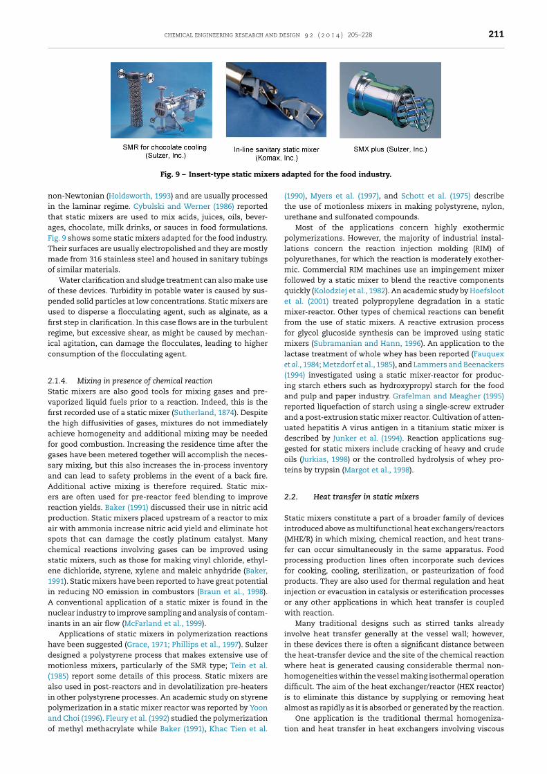
echnique, offering a broader view on the course of mixing. Forxample, dilution-type experiments can be complemented byeactive methods. Fig. 19 shows the flow patterns in a split-nd-recombine mixer obtained by using the dye water bluend those revealed by the iron rhodanide reaction. Comparinghe results helps point out technical artifacts and pinpoint theeal physical phenomena taking place.
.2. Quantitative techniques
sing these methods, the characteristic mixing time is linkedo segregation levels in a reactive flow or a flow containinghemical species whose concentrations are influenced by theixing qualities. The concentrations are measured by optical
echniques, and following the associated case-specific physi-
al phenomena, the mixing time is calculated using physicalodels.4.2.1. Monitoring species concentrationThe spatial or temporal in situ monitoring of species concen-tration is a quantitative method for measuring mixing and islargely used when evaluating the performance of stirred tanksand macro-scale static mixers using the coefficient of variance(Paul et al., 2004).
The temporal or spatial mean and variance can be cal-culated to give a measure of the segregation intensity andtherefore the “evenness” of concentration (Men et al., 2007).
One-dimensional profiles or two-dimensional maps ofspecies concentration, depending on the measurement tech-nique used are obtained to determine a striation thicknessdistribution, thus giving information about the scales ofsegregation. For one-dimensional concentration profiles, themeasurement is representative of the concentration averagedthrough the channel or device depth. It is pertinent only ifthe flow structure is two-dimensional and the concentrationsare constant throughout the channel depth. Both types ofinformation allow the characteristic fluid lamellae scale in thedevice to be identified, which in turn can be related to mixingtime.
The species concentration is typically detected using pho-tometric and fluorescence methods. Salmon et al. (2005) usedRaman spectroscopy for the analysis of reaction–diffusiondynamics. Confocal Raman imaging is a nonintrusive tech-nique that can give the local concentrations of chemicalspecies by scanning a sampling volume of a few microme-ters in size throughout the entire system. Raman spectroscopyis routinely used in chemical analysis and has recently beencoupled with microfluidics. Salmon et al. (2005) analyzed inter-diffusion of pure liquids by coupling Raman imaging andmicrofluidics on quantitative grounds. Raman spectra at agiven location in the microchannel were recorded using a con-focal Raman microscope. The samples were illuminated byradiation from an argon-ion laser. Backscattered light was col-lected by the objective, and a grating dispersed the Ramanspectrum onto a charge-coupled device. The local concentra-tions of the fluids could be probed from the intensities ofnonoverlapping Raman bands specific to each liquid. Concen-tration maps were then obtained using x–y microactuators todisplace the microchannel under the microscope objective.
For photometric, fluorescence, and Raman (using visiblelight) detection techniques, the device must be optically trans-parent. For infrared detection, the device must be transparentto infrared radiation wavelengths.
4.2.2. Competing parallel reactionsThis technique, namely the chemical probe, entailscompetitive-consecutive or competitive-parallel reactions,which are based on the chemical result of the local injectionof a reagent in stoichiometric deficit in the main flow. Theprinciple is to carry out two reactions in parallel that bothuse a common reactant, which they compete for. One ofthe reactions should be very fast (quasi-instantaneous) withcharacteristic time tr1, so that it proceeds only if mixing isideal (extremely rapid). The other reaction should be fast(but slower than the first) and takes place when there is anexcess of the common reactant, when mixing is slow andnon-ideal. The second reaction has characteristic time tr2
close to the mixing time tm. The local chemical reaction thusresults from a competition between mixing at microscalesand the reaction kinetics. Quantitative information can be
obtained on the yield of the secondary (slower) reaction.Consequently, mixing performance is characterized by the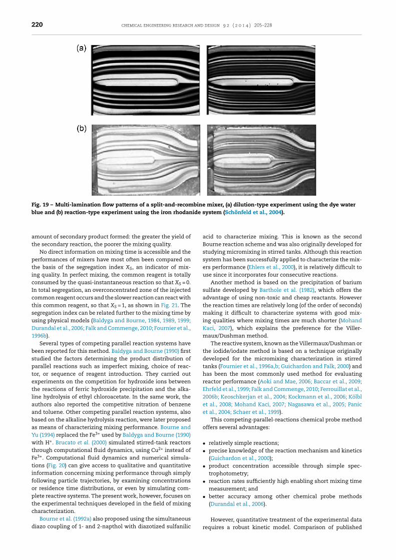
220 chemical engineering research and design 9 2 ( 2 0 1 4 ) 205–228
Fig. 19 – Multi-lamination flow patterns of a split-and-recombine mixer, (a) dilution-type experiment using the dye waterblue and (b) reaction-type experiment using the iron rhodanide system (Schönfeld et al., 2004).
amount of secondary product formed: the greater the yield ofthe secondary reaction, the poorer the mixing quality.
No direct information on mixing time is accessible and theperformances of mixers have most often been compared onthe basis of the segregation index XS, an indicator of mix-ing quality. In perfect mixing, the common reagent is totallyconsumed by the quasi-instantaneous reaction so that XS = 0.In total segregation, an overconcentrated zone of the injectedcommon reagent occurs and the slower reaction can react withthis common reagent, so that XS = 1, as shown in Fig. 21. Thesegregation index can be related further to the mixing time byusing physical models (Baldyga and Bourne, 1984, 1989, 1999;Durandal et al., 2006; Falk and Commenge, 2010; Fournier et al.,1996b).
Several types of competing parallel reaction systems havebeen reported for this method. Baldyga and Bourne (1990) firststudied the factors determining the product distribution ofparallel reactions such as imperfect mixing, choice of reac-tor, or sequence of reagent introduction. They carried outexperiments on the competition for hydroxide ions betweenthe reactions of ferric hydroxide precipitation and the alka-line hydrolysis of ethyl chloroacetate. In the same work, theauthors also reported the competitive nitration of benzeneand toluene. Other competing parallel reaction systems, alsobased on the alkaline hydrolysis reaction, were later proposedas means of characterizing mixing performance. Bourne andYu (1994) replaced the Fe3+ used by Baldyga and Bourne (1990)with H+. Brucato et al. (2000) simulated stirred-tank reactorsthrough computational fluid dynamics, using Cu2+ instead ofFe3+. Computational fluid dynamics and numerical simula-tions (Fig. 20) can give access to qualitative and quantitativeinformation concerning mixing performance through simplyfollowing particle trajectories, by examining concentrationsor residence time distributions, or even by simulating com-plete reactive systems. The present work, however, focuses onthe experimental techniques developed in the field of mixingcharacterization.
Bourne et al. (1992a) also proposed using the simultaneousdiazo coupling of 1- and 2-napthol with diazotized sulfanilic
acid to characterize mixing. This is known as the secondBourne reaction scheme and was also originally developed forstudying micromixing in stirred tanks. Although this reactionsystem has been successfully applied to characterize the mix-ers performance (Ehlers et al., 2000), it is relatively difficult touse since it incorporates four consecutive reactions.
Another method is based on the precipitation of bariumsulfate developed by Barthole et al. (1982), which offers theadvantage of using non-toxic and cheap reactants. Howeverthe reaction times are relatively long (of the order of seconds)making it difficult to characterize systems with good mix-ing qualities where mixing times are much shorter (MohandKaci, 2007), which explains the preference for the Viller-maux/Dushman method.
The reactive system, known as the Villermaux/Dushman orthe iodide/iodate method is based on a technique originallydeveloped for the micromixing characterization in stirredtanks (Fournier et al., 1996a,b; Guichardon and Falk, 2000) andhas been the most commonly used method for evaluatingreactor performance (Aoki and Mae, 2006; Baccar et al., 2009;Ehrfeld et al., 1999; Falk and Commenge, 2010; Ferrouillat et al.,2006b; Keoschkerjan et al., 2004; Kockmann et al., 2006; Kölblet al., 2008; Mohand Kaci, 2007; Nagasawa et al., 2005; Panicet al., 2004; Schaer et al., 1999).
This competing-parallel-reactions chemical probe methodoffers several advantages:
• relatively simple reactions;• precise knowledge of the reaction mechanism and kinetics
(Guichardon et al., 2000);• product concentration accessible through simple spec-
trophotometry;• reaction rates sufficiently high enabling short mixing time
measurement; and• better accuracy among other chemical probe methods
(Durandal et al., 2006).
However, quantitative treatment of the experimental datarequires a robust kinetic model. Comparison of published

chemical engineering research and design 9 2 ( 2 0 1 4 ) 205–228 221
Fig. 20 – Computational fluid dynamics (CFD) as a powerful tool for mixing analysis, (a) concentration contours in theChemineer WVM pre-distribution tab configuration and (b) turbulent streamlines in the Sulzer CompaX additive-dosingmixer.
crom
mictt(meifsctft
5
T(miDoohntp
Fig. 21 – Schematic diagram of the mi
odels shows differences due to the sensitivity of theodine-forming reaction to mixing conditions (ionic strength,oncentration, etc.). The ideal approach is to re-determinehe reaction kinetics using the specific parameters of the sys-em adopted employing modern techniques for fast reactionsBourne, 2008). Despite this fact, the Villermaux/Dushman
ethod for characterizing the extent of micromixing throughxamining the iodine yield gives qualitatively consistent andntelligible results. With special attention given to the uni-ormity of reactive system characteristics, this method isuitable for ranking different mixers or different operatingonditions (Bourne, 2008). Quantitative comparison of mixingimes measured in different reactor configurations using dif-erent methods remains a delicate procedure that must takehe above remarks into consideration.
. Iodide/iodate chemical probe method
his chemical probe method, developed by Fournier et al.1996a,b) to study partial segregation in stirred tanks, imple-
ents a system of parallel competing reactions producingodine. The coupling of the borate neutralization and theushman reaction in this system allows the measurementf mixing efficiency in reactors by monitoring the amountf iodine produced. As mentioned before, this techniqueas been extensively used in different types of reactors. Aovel adaptive procedure recently developed by the authors
o improve the reliability of the iodide/iodate method will beresented and discussed.
ixing process in the chemical probe.
5.1. Chemical system and mixing models
5.1.1. Iodide/iodate reaction systemIn this method, borate neutralization (Eq. (6)) is quasi-instantaneous with characteristic time tr1; the second, theDushman reaction (Eq. (7)) (Dushman, 1904) is slower and hascharacteristic time tr2 close to the mixing time tm. The bal-anced reactions can be modeled as follows:
Reaction 1 : H2BO3− + H+↔ H3BO3 tr1� tr2 (6)
Reaction 2 : 5I− + IO3− + 6H+↔ 3I2+ 3H2O tr2≈ ∼tm (7)
The iodine I2 further reacts with iodide ions I−, yielding I−3ions following the quasi-instantaneous equilibrium reaction:
Reaction3 : I− + I2KB←→I−3 (8)
The kinetics of the three reactions was established byGuichardon et al. (2000). The characteristic times of reactions(1) and (2) are:
tr1 =Min([H2BO−3 ]0; [H+]0)
(r1)t=0(9)
tr2 =Min((3/5)[I−]0; 3[IO−3 ]0; 1/2[H+]0)
(r2)t=0(10)

222 chemical engineering research and design 9 2 ( 2 0 1 4 ) 205–228
where the brackets denote the reagent concentration and r1
and r2 are the respective rates of reactions (1) and (2):
r1 = k1[H2BO−3 ][H+] (11)
r2 = k2[H+]2[I−]2[IO−3 ] (12)
where k1 and k2 are the reaction rate constants of reactions (1)and (2), respectively. Here k1 = 1011 L mol−1 s and k2 is a func-tion of ionic strength, � as defined by Guichardon et al. (2000):
For � < 0.166 M : log10(k2) = 9.28105 − 3.664√
�
For � > 0.166 M : log10(k2) = 8.383 − 1.5112√
� + 0.23689�
(13)
The principle of this method is to add, in stoichiometricdeficit, a small quantity of sulfuric acid H+ to an initial mix-ture of I−, IO−3 , and H2BO−3 . In perfect mixing, the injected H+
is totally consumed by the quasi-instantaneous reaction (1) inEq. (6) and hence there is no formation of iodine I2. When themixing process is not sufficiently fast to sustain reaction (1),the local overconcentration of H+ produces iodine I2 by reac-tion (2) (Eq. (7)), which reacts with iodide ions I− to yield I−3ions (Eq. (8)): it modifies the absorbance of the final solutionthat is detected by the spectrometer, used to deduce the con-centration of produced I−3 . Therefore, the selectivity in I2 is ameasure of molecular-scale segregation and indicates mixingquality.
The characteristic segregation index XS is defined by theexpression:
XS = Y
YST(14)
where Y is the ratio of the quantity of H+ transformed into I2
following the second reaction to the total quantity of injectedH+ and YST is the value of Y in the case of total segregation. XS
is given for open loop flows by Villermaux (1986) as:
XS =2([I2] + [I−3 ])
[H+]0
(Qp
QH++ 1
)([H2BO−3 ]
6[IO−3 ]0+ 1
)(15)
where Qp and QH+ are respectively the flow rate of the mainstream and the injected sulfuric acid.
The mass balance on iodine I2 atoms leads to the followingexpression (Fournier et al., 1996a,b):
[I2]2 −((
35
)[I−]0 −
85
[I−3 ])
[I2] + 35
[I−3 ]
5KB= 0 (16)
where KB is the equilibrium constant of reaction (3) (Eq. (8))which depends on the solution temperature:
log10KB = 555T+ 7355 − 2575 log10(T) (17)
At T = 298 K the equilibrium constant KB = 702 mol−1.
5.1.2. Adaptive procedureRecently, the conventional chemical probe procedure wasused to compare two curved 2 × 4 mm rectangular ducts withdifferent radii of curvature (Habchi et al., 2011). A first exper-
iment, with distributed wall injections and a given set ofspecies concentrations fixing a “high rate” for reaction (2),demonstrated that the selectivity did not vary with Reynoldsnumber. In fact, the channel walls are corrugated, and nearthe solid walls the flow is governed by the roughness size. Thechemical probe could not discriminate between the geome-tries when a wall injection is applied. A second experiment,with a slow (“low-rate”) reaction (2) and unique injection pointat the duct inlet, also did not show variation with Reynoldsnumber, because the measurement volume depends on theflow velocity. The Reynolds numbers were relatively low dueto the small size of the duct sides, so that the measure-ments are inevitably hindered by mesomixing effects. Thechallenge was thus to adapt the chemical method for charac-terizing global mixing by enlarging the measurement volumeso as to capture and take into account all the mixing scales.To meet this challenge, a new protocol was proposed thatinvolves pre-adjusting the measurement volume to the differ-ent Reynolds numbers by adapting the kinetics of reaction (2)to each Reynolds number, leading to more relevant results forthe segregation index XS. The second reaction time tr2 can beadjusted by varying the initial reagent concentrations; how-ever, as it is quite difficult to vary the initial concentrationsof I−, IO−3 , and H2BO−3 constituting the initial solution becausethey are linked by the pH, the choice was made to vary the H+
concentrations injected into the main flow. Accordingly, foreach Reynolds number, the second reaction time is calculatedin such a way as to obtain a constant measurement volumecomputed from the length over which reaction (2) takes place,Lr2 = Wtr2. Therefore, when the Reynolds number and the flowspeed increase, the second reaction time is decreased by thesame factor by increasing the H+ concentration. This methodreveals the relative mixing improvement when the Reynoldsnumber is increased, and allows comparing different reactorgeometries.
Finally, the measured segregation index is related to themixing time by the engulfment model (Baldyga and Bourne,1989) for turbulent regime and by the stretching efficiencymodel (Falk and Commenge, 2010) for laminar one.
5.2. Micromixing models
The segregation index XS provides qualitative informationon global mixing dependent on the chemical system. Therelated quantitative parameter is the intrinsic mixing time,tm independent of the reactive conditions, which can be iden-tified through mixing models devised on phenomenologicalgrounds.
5.2.1. Engulfment modelSeveral models exist for determining mixing time and turbu-lent energy dissipation rate. Baldyga and Bourne (1984, 1989)have developed a complex model, the engulfment model (E-model), based on the assumption of first-order-law growth ofthe incorporated reagent volume into spiral marbled struc-tures, shown in Fig. 22, that are later homogenized under thestretching effects until near-Batchelor scales, and then molec-ular diffusion.
The E-model is used for the turbulent flow regime. Thefirst of its steps is the growth of the volume Vi containing thespecies i:
dVi
dt= EVi (18)
where the engulfment rate E, the inverse of the mixing time,is related to the TKE dissipation rate, ε and the kinematic

chemical engineering research and design 9 2 ( 2 0 1 4 ) 205–228 223
Fig. 22 – Principle of the engulfment model.A
vB
E
ot
wef
brrdNtim(ffia
5Itotvcsca1wccoa
pu
dapted from Baldyga and Bourne (1999).
iscosity, � following the scale law analysis by Baldyga andourne (1989):
= 1tm= 0.05
(ε
�
)1/2(19)
Expressing Eq. (18) in terms of mass balance, the growthf the uniform mixing zone of concentration ci is given by theemporal differential equation:
dci
dt= E(〈ci〉 − ci) + Ri (20)
here 〈ci〉 refers to the mean concentration value of i in thenvironment when mixing is completed and Ri is the rate oformation of substance i by the chemical reaction.
To find the rate of variation of each species, Eq. (20) muste solved as a function of time for each species involved ineactions until the sulfuric acid concentration tends to zeroesulting in a system of nine nonlinear equations for theifferent reagents in the iodide/iodate reaction system. Theewton–Raphson iterative method is employed and computa-
ions are made with MATLAB software. The calibration curves obtained by the set of XS solutions found by sweeping the
ixing-time parameter, tm. From the experimental XS valueEq. (15)), the mixing time can be determined by the inverseunction XS = f(tm). The corresponding curve can be used tond the mixing time, tm when the segregation index value isvailable from experiments.
.2.2. Stretching efficiency modeln laminar shear flow, it is known that the characteris-ic dimension of the structure decreases in the directionrthogonal to the elongation. Diffusion and convection arehen competitive processes, but according to the shear ratealue, for large segregation scales, diffusion process is slowompared to convection and mixing is almost controlled bytretching. At fine segregation scales, diffusion becomes theontrolling step. This problem has been addressed by severaluthors (Baldyga and Bourne, 1983; Li et al., 2005; Ou and Ranz,983a,b) and reinvestigated by Baldyga and Bourne (1984),ho considered the total mixing time to be the simultaneous
ontribution of the diffusion time and the shear stretchingharacteristic time and proposed to calculate the mixing timef intertwined lamellae by considering the striation thicknessnd the shear rate in the reactor.
Based on this approach, the stretching efficiency model
roposed for laminar regimes, by Falk and Commenge (2010) issed to calculate the mixing time. Baldyga and Bourne (1984)suggest calculating the mixing time in laminar flow by thefollowing equation:
tm =arcsinh((0.76 �̇ı2
0)/Dm)
2 �̇(21)
where ı0 is the initial striation thickness, Dm the molecular dif-fusion of water and �̇ the “efficient” generalized shear rate formixing in the reactor. In this sense, �̇ is assumed to representthe rate of creation of intermaterial area:
�̇ = 1av
dav
dt(22)
where av is the intermaterial area per unit volume.However, determination of �̇ is not trivial and numerical
or analytical solutions are needed. Falk and Commenge (2010)estimate the mean power dissipation rate per unit mass offluid ε̄ and the “efficient” generalized shear rate for energydissipation �̇m in laminar flow from the Hagen–Poiseuille law.Hence, ε̄ and �̇m can be derived in terms of the channelhydraulic diameter Dh, the mean flow velocity W, and thekinematic viscosity of the fluid �:
ε̄ = 32�W2
D2h
(23)
�̇m =(
ε̄
2�
)1/2
(24)
The mean power dissipation rate per unit mass of fluidε̄ can also be calculated, for all flow regimes, from the netpressure drop over the entire reactor length P by:
ε̄ = QP
�V(25)
where Q is the volume flow rate of the main flow and V is thetotal fluid volume between the two pressure-drop measure-ment points.
The initial striation thickness ı0 depends in turn on theexperimental procedure and the injection mode. Under opti-mal conditions, the acid is injected in the direction of the mainflow with an equal velocity to avoid a jet impact with the flow.In this case, the initial striation thickness can be estimatedusing:
ı20
4W = Qinj (26)

224 chemical engineering research and design 9 2 ( 2 0 1 4 ) 205–228
where Qinj is the volume flow rate of the injected acid solution.Given the above conditions, the initial striation thickness thusequals the injection needle diameter d.
For the ideal case where the entire mean shear rate of theflow contributes to the mixing process, application of the rela-tion in Eq. (21) gives the following expression for the mixingtime:
tm = Dh
8Warcsinh
[3.04
(d
Dh
)2
Pe
](27)
where Pe = WDh/Dm is the Péclet number.In reality, however, several objections can be raised based
on flow phenomena. To calculate the mixing time, the initialconcentration field is considered to be constituted of inter-wined lamellae of the two streams. This state is not achieveddirectly after the injection point and needs additional time forfull development.
Also, the model assumes that the slabs constantly undergoconstant shearing rates. This is a crude assumption, sincethe lamellae do not always undergo constant deformationrate; they are stretched and rotated in usually complex three-dimensional flow fields. In addition, the orientation of thedeformation field plays an important role in the mixing pro-cess. A fluid lamella may go by in a state in which it isperpendicular to the stretching field, increasing its striationthickness and hence reducing the concentration gradient andconsequently the mixing rate.
These considerations lead to the conclusion that only partof the mechanical energy consumed is used for mixing. Falkand Commenge (2010) use the concept of mixing efficiency �
proposed by Ottino et al. (1979):
� = �̇
�̇m= �̇
(ε̄/2�)1/2(28)
Taking the above relation into consideration, the expres-sion of the mixing time introduced in Eq. (21) finally becomes:
tm = Dh
8W�arcsinh
[3.04
(d
Dh
)2
� Pe
](29)
Comparison of the experimental values of tm to those cal-culated using the model in Eq. (29) gives access to the mixingefficiency �.
6. Conclusions
This review reports on the static mixing process in industrialapplications—the mechanisms, the devices, the characteriza-tion methodologies—in an attempt to summarize the basicinformation needed to handle a mixing application on anindustrial scale.
The first part of the study surveys the available commer-cial models of static mixers and heat exchangers/reactors andtheir fields of application. All have the common characteristicsof safe operating conditions, compactness, good reaction con-trol, high yields and selectivities, energy savings, fewer unitoperations, and cheaper processing.
The emergence of computer-assisted design and compu-tational fluid dynamics facilitates the evolution of conceptualdesigns and the refinement of the principal configurations.
This process would have been much slower had it reliedmerely on physical experiments; in addition, experimentscannot provide the precise local measurements that areneeded to understand the effects of complex geometries.There is still, of course, substantial room for further improve-ment and new designs and principles. For example, someinnovative designs promote axial rather than radial mixingby approximating the residence time distribution of a contin-uous stirred-tank reactor (Nauman et al., 2002). Even the mostwidely studied geometries can still be further optimized. ForKenics-type helices, for example, the optimal angle of twist,the ratio of the element’s length to its diameter, the offsetangle between two consecutive elements, and the homogene-ity of the geometric parameters for all elements as opposedto sequential position-dependent variations are all decisivefactors for the overall performance that have yet to be deter-mined.
Fouling resistance, corrosion, maintenance, and cleaningoperations are at present problems in such devices. Academiaseems overly obsessed with theoretical gains in mixing andheat transfer, and the tools to address technical compli-cations in the implementation and production phases arestill immature and need extensive development. Moreover,laboratory-scale optimization processes are leading to newdesigns that prove more potent than the available models, yetindustrialization seems slow: sometimes it can take years forresearch prototypes to become available in the markets, if ever.Another issue is the scalability and extrapolation potentialfor each of the proposed configurations, especially those fea-turing a wide variety of geometric parameters and operatingconditions like the microstructured heat exchanger/reactors,where only few technologies have been applied to industrialsyntheses.
Even so, more robust and professional designs are neededand field trials must be conducted to evaluate the potentialin industrial environments. For instance, helical inserts arepromising in terms of heat transfer capacity, yet in most cases,studies have examined the insertion of elements in only a sin-gle channel; such studies in an entire heat exchanger/reactorcould be interesting. Conditions may vary widely betweena factory and a research facility. Currently, the trend is todevelop and commercialize generic models for a wide varietyof applications; such models exhibit satisfactory performance.The future need is for designs that are optimal, in some sense,for a particular application where they can operate with max-imum efficiency.
The second part of the review is devoted to the funda-mentals and measurement techniques for mixing. Severalapproaches have been proposed to understand the mixingmechanism, the most pertinent of which is the definition ofthree different mixing scales, macro-, meso-, and micromix-ing. The intrinsic parameters of the largest and smallest scaleshave been more or less unveiled, but the link between thetwo, namely the mesomixing scale, remains hard to conquer.At this scale, inertial-convective mixing depends on severalparameters and is sensitive to various conditions; its mas-tery requires further investigation using modern analyticalapproaches and measurement techniques.
Mixing characterization is of increasing importance inmodern applications for various reasons, the most basic ofwhich is to differentiate and classify the available devices soas to be able to choose the proper configuration for a spe-cific application. This report surveys existing experimentalmethods available for characterizing mixing and its outcomes,
some of which have been adopted from chemical engineer-ing, biology, or analytical chemistry. Information concerning
chemical engineering research and design 9 2 ( 2 0 1 4 ) 205–228 225
tltbmtImrsbwa
mDdmmwc
eewepnhapatuc
R
A
A
A
A
A
A
A
A
A
A
he main principles, the type of information obtained, and theimitations of each technique is provided, thus allowing iden-ification of mixing performance characteristics that cannote measured with existing techniques. Most of the experi-ental techniques employ optical methods, which require
ransparent devices or at least transparent viewing windows.n practical applications, however, transparent construction
aterials may not be well adapted to the harsh industrial envi-onment of the chemical and physical processes encountered,o that these characterization methods may not be applica-le. This shows the importance of coupling academic studiesith industrial issues, when possible, for the improvement
nd control of process performance.Quantitative characterization needs robust theoretical
odels to support and process the experimental findings.eveloping adaptive procedures and modernizing scientificatabases with state-of-the-art techniques is crucial to ensureaximum precision of the results delivered by classicalethodologies, as in the case of the chemical probe methodhose outcome strongly depends on the specific experimental
onditions and parameters adopted in each individual study.Static mixers and multifunctional heat exchang-
rs/reactors are currently at the center of active researchndeavors due to their promising capabilities in a worldhere energy efficiency is no longer a mere detail. Alarming
nvironmental degradation and resource depletion, accom-anied with continuing high-standard lifestyle requirements,ecessitate proper exploitation of available power to produceigh-quality commodities while minimizing compromisesnd damage to delicate ecosystems. It is hoped that theresent work will help guide the potential industrial orcademic user of static mixers in choosing a device andhe relevant mixing characterization method based on annderstanding of the associated mixing mechanisms in theontext of energy-efficient processing.
eferences
jakh, A., Kestoras, M.D., Toe, R., Peerhossaini, H., 1999. Influenceof forced perturbations in the stagnation region on Görtlerinstability. AIAA J. 37, 1572–1577.
lliet-Gaubert, M., Sardeing, R., Xuereb, C., Hobbes, P., Letellier,B., Swaels, P., 2006. CFD analysis of industrial multi-stagedstirred vessels. Chem. Eng. Proc. 45, 415–427.
nxionnaz, Z., Cabassud, M., Gourdon, C., Tochon, P., 2008. Heatexchanger/reactors (HEX reactors): concepts, technologies:state-of-the-art. Chem. Eng. Proc. 47, 2029–2050.
oki, N., Mae, K., 2006. Effects of channel geometry on mixingperformance of micromixers using collision of fluid segments.Chem. Eng. J. 118, 189–197.
ref, H., 1984. Stirring by chaotic advection. J. Fluid Mech. 143,1–21.
ubin, J., Naude, I., Bertrand, J., Xuereb, C., 2000. Blending ofNewtonian and Shear-Thinning fluids in a tank stirred with ahelical screw agitator. Chem. Eng. Res. Des. 78, 1105–1114.
ubin, J., Mavros, P., Fletcher, D.F., Bertrand, J., Xuereb, C., 2001.Effect of axial agitator configuration (up-pumping,down-pumping, reverse rotation) on flow patterns generatedin stirred vessels. Chem. Eng. Res. Des. 79, 845–856.
ubin, J., Fletcher, D.F., Xuereb, C., 2005. Design of micromixersusing CFD modeling. Chem. Eng. Sci. 60, 2503–2516.
ubin, J., Xuereb, C., 2006. Design of multiple impeller stirredtanks for the mixing of highly viscous fluids using CFD. Chem.Eng. Sci. 61, 2913–2920.
ubin, J., Kresta, S.M., Bertrand, J., Xuereb, C., Fletcher, D.F., 2006.Alternate operating methods for improving the performance
of continuous stirred tank reactors. Chem. Eng. Res. Des. 84,569–582.
Azer, N.Z., Lin, S.T., 1980. Augmentation of forced flow boilingheat transfer with Kenics motionless mixers. Ind. Eng. Chem.Proc. Des. Dev. 19, 246–250.
Baccar, N., Kieffer, R., Charcosset, C., 2009. Characterization ofmixing in a hollow fiber membrane contactor by theiodide–iodate method: Numerical simulations andexperiments. Chem. Eng. J. 148, 517–524.
Baker, J.R., 1991. Motionless mixers stir up new uses. Chem. Eng.Prog. 87, 32–38.
Bakker, M.J., 1949. Dispositif pour préparer du béton ou unematière analogue. French Patent, 959,155.
Baldyga, J., Bourne, J.R., 1983. Distribution of striation thicknessfrom impingement mixers in reaction injection molding.Polym. Eng. Sci. 23 (10), 556–559.
Baldyga, J., Bourne, J.R., 1984. A fluid mechanical approach toturbulent mixing and chemical reaction. Part II. Micro-mixingin the light of turbulence theory. Chem. Eng. Commun. 28,243–258.
Baldyga, J., Bourne, J.R., 1986. Transport phenomena andhydrodynamics of complex flows. In: Cheremisinoff, N.P. (Ed.),Encyclopedia of Fluid Mechanics, vol. 1. Gulf PublishingCompany, Houston, TX, p. 145.
Baldyga, J., Bourne, J.R., 1988. Simplification of micromixing inhomogeneous stirred tank reactors. Chem. Eng. Res. Des. 66,33.
Baldyga, J., 1989. Turbulent mixer model with application tohomogeneous instantaneous chemical reactions. Chem. Eng.Sci. 44, 1175–1182.
Baldyga, J., Bourne, J.R., 1989. Simplification of micro-mixingcalculations: I. Derivation and application of a new model.Chem. Eng. J. 42, 83–92.
Baldyga, J., Bourne, J.R., 1990. The effect of micromixing onparallel reactions. Chem. Eng. Sci. 45 (4), 907–916.
Baldyga, J., Bourne, J.R., 1992. Interactions between mixing onvarious scales in stirred tank reactors. Chem. Eng. Sci. 47,1839.
Baldyga, J., Bourne, J.R., Yang Yang, 1993. Influence of feed pipediameter on mesomixing in stirred tank reactors. Chem. Eng.Sci. 48, 3383–3390.
Baldyga, J., Bourne, J.R., Zimmermann, B., 1994. Investigation ofmixing in jet reactors using fast, competitive consecutivereactions. Chem. Eng. Sci. 49, 1937.
Baldyga, J., Pohorecki, R., 1995. Turbulent micro-mixing inchemical reactors – a review. Chem. Eng. J. 58, 183–195.
Baldyga, J., Bourne, J.R., Dubuis, B., Etchells, A.W., Gholap, R.V.,Zimmermann, B., 1995. Jet reactor scale-up for mixingcontrolled reactions. Chem. Eng. Res. Des. 73, 497.
Baldyga, J., Bourne, J.R., 1999. Turbulent Mixing and ChemicalReactions. Wiley, Chichester.
Barthole, J.P., David, R., Villermaux, J., 1982. A new chemicalmethod for the study of local micromixing conditions inindustrial stirred tanks. ACS Symp. Ser. 196,545–554.
Batchelor, G.K., 1953. The theory of Homogeneous Turbulence.Cambridge University Press, Cambridge, England.
Bayat, M., Rahmanipour, M.R., Taheri, M., Pashai, M., Sharifzadeh,S., 2012. A comparative study of two different configurationsfor exothermic-endothermic reactor. Chem. Eng. Proc. 52,63–73.
Bergles, A.E., 1995. Heat transfer enhancement – the maturing ofsecond generation heat transfer technology. Heat Transf. Eng.18, 573–579.
Bourne, J.R., Kut, O.M., Lenzner, J., 1992a. An improved reactionsystem to investigate micromixing in high-intensity mixers.Ind. Eng. Chem. Res. 31, 949–958.
Bourne, J.R., Lenzner, J., Petrozzi, S., 1992b. Micromixing in staticmixers: an experimental study. Ind. Eng. Chem. Res. 31,1216–1222.
Bourne, J.R., Yu, S., 1994. Investigation of micro-mixing in stirred
tank reactors using parallel reactions. Ind. Eng. Chem. Res. 33,41–55.
226 chemical engineering research and design 9 2 ( 2 0 1 4 ) 205–228
Bourne, J.R., 2008. Comments on the iodide/iodate method forcharacterising micromixing. Chem. Eng J. 140 (1–3), 638–641.
Branebjerg, J., Fabius, B., Gravesen, B., 1995. Application ofminiature analysers: from microfluidic components to (TAS).In: Van den Berg, A., Bergfeld, P. (Eds.), Micro Total AnalysisSystems. Kluwer, Dordrecht, pp. 141–151.
Braun, H., Horen, A., Scheniders, T., Vortmeyer, K., Pfost, H., 1998.Measurement of the mixing quality in premix combustors.Energy Convers. Manage. 39, 1991–1999.
Brucato, A., Ciofalo, M., Grisafi, F., Tocco, R., 2000. On thesimulation of stirred tank reactors via computational fluiddynamics. Chem. Eng. Sci. 55, 291–302.
Cabaret, F., Rivera, C., Fradette, L., Heniche, M., Tanguy, P.A., 2007.Hydrodynamics performance of a dual shaft mixer withviscous Newtonian liquids. Chem. Eng. Res. Des. 85, 583–590.
Carrière, P., 2006. Lyapunov spectrum determination from theFEM simulation of a chaotic advecting flow. Int. J. Num.Methods Fluids 50, 555–577.
Castelain, C., Mokrani, A., Legentilhomme, P., Peerhossaini, H.,1997. Residence time distribution in twisted pipe flows:helically coiled system and chaotic system. Exp. Fluids 22,359–368.
Chemineer, Inc., 1998. Kenics: static mixing technology. Bulletin,800 (commercial documentation).
Chemineer, Inc., 2004. Greerco Pipeline Mixer. Bulletin, 122(commercial documentation).
Chen, S.J., 1975. Static mixing of polymers. Chem. Eng. Prog. 71,80–83.
Cybulski, A., Werner, K., 1986. Static mixers-criteria forapplications and selection. Int Chem Eng. 26 (1), 171–180.
Durandal, C., Lemenand, T., Della Valle, D., Peerhossaini, H., 2006.A chemical probe for characterizing turbulent micro-mixing.ASME FEDSM 98146, 1091–1099.
Dushman, S., 1904. The rate of the reaction between iodic andhydriodic acids. J. Phys. Chem. 8, 453–482.
Ehlers, S., Elgeti, K., Menzel, T., Weissmeier, G., 2000. Mixing inthe offstream of a microchannel system. Chem. Eng. Proc. 39,291–298.
Ehrfeld, W., Golbig, K., Hessel, V., Lowe, H., Richter, T., 1999.Characterisation of mixing in micromixers by a test reaction:single mixing units and mixer arrays. Ind. Eng. Chem. Res. 38,1075–1082.
Falk, L., Commenge, J.M., 2010. Performance comparison ofmicro-mixers. Chem. Eng. Sci. 65, 405–411.
Fan, L.T., Lin, S.T., Azer, N.Z., 1978. Surface renewal model ofcondensation heat transfer in tubes with in-line static mixers.Int. J. Heat Mass Transf. 21, 849–854.
Fangary, Y.S., Barigou, M., Seville, J.P.K., Parker, D.J., 2000. Fluidtrajectories in a stirred vessel of non-newtonian liquid usingpositron emission particle tracking. Chem. Eng. Sci. 55,5969–5979.
Fauquex, P.F., Flaschel, E., Renken, A., 1984. Développement d’unréacteur enzymatique lit fluidisé à mélangeurs statiques:application à l’hydrolyse du lactose du petit-lait. Chimia 38,262–269.
Fentiman, N.J., St Hill, N., Lee, K.C., Paul, G.R., Yianneskis, M.,1998. A novel profiled blade impeller for homogenization ofmiscible liquids in stirred vessels. Chem. Eng. Res. Des. 76,835–842.
Ferrouillat, S., Tochon, P., Garnier, C., Peerhossaini, H., 2006a.Intensification of heat transfer and mixing in multifunctionalheat exchangers by artificially generated streamwise vorticity.Appl. Therm. Eng. 26, 1820–1829.
Ferrouillat, S., Tochon, P., Peerhossaini, H., 2006b. Micro-mixingenhancement by turbulence: application to multifunctionalheat exchangers. Chem. Eng. Proc. 45, 633–640.
Ferrouillat, S., Tochon, P., Della Valle, D., 2006c. Open loopthermal contrôle of exothermal chemical reactions inmultifunctional heat exchangers. Int. J. Heat Mass Transf.15–16 (49), 2479–2490.
Fiebig, M., 1995. Embedded vortices in internal flow: heat transfer
and pressure loss enhancement. Int. J. Heat Fluid Flow 16,376–388.Fleury, P.A., Meyer, T., Renken, A., 1992. Solution polymerizationof methyl-methacrylate at high conversion in a recycletubular reactor. Chem. Eng. Sci. 47, 2597–2602.
Fournier, M.C., Falk, L., Villermaux, J., 1996a. A new parallelcompeting reaction system for assessing micro-mixingefficiency - Experimental approach. Chem. Eng. Sci. 51,5053–5064.
Fournier, M.C., Falk, L., Villermaux, J., 1996b. A new parallelcompeting reaction system for assessing micro-mixingefficiency - Determination of micro-mixing time by a simplemixing model. Chem. Eng. Sci. 51, 5187–5192.
Ghanem, A., Habchi, C., Lemenand, T., Della Valle, D.,Peerhossaini, H., 2013a. Energy efficiency in process industry –high-efficiency vortex (HEV) multifunctional heat exchanger.Renew. Energy 56, 96–104.
Ghanem, A., Lemenand, T., Della Valle, D., Peerhossaini, H.,2013b. Transport phenomena in passively manipulatedchaotic flows: split-and-recombine reactors. ASMEFEDSM2013 16077, Nevada, USA, July 7–11.
Goldshmid, J., Samet, M., Wagner, M., 1986. Turbulent mixing athigh dilution ratio in a Sulzer–Koch static mixer. Ind. Eng.Chem. Proc. Des. Dev. 25, 108–116.
Gough, M.J., Rogers, J.V., 1987. Reduced fouling by enhanced heattransfer using wire matrix radial mixing elements. AIChESymp. Ser. 83, 16–21.
Grace, C.D., 1971. Static mixing and heat transfer. Chem. Process.Eng. July, 57–59.
Grafelman, D.D., Meagher, M.M., 1995. Liquefaction of starch by asingle screw extruder and post-extrusion static-mixer reactor.J. Food Eng. 24, 529–542.
Guichardon, P., Falk, L., 2000. Characterisation of micro-mixingefficiency by the iodide-iodate reaction system. Part I.Experimental procedure. Chem. Eng. Sci. 55, 4233–4243.
Guichardon, P., Falk, L., Villermaux, J., 2000. Characterisation ofmicro-mixing efficiency by the iodide-iodate reaction system.Part II: kinetic study. Chem. Eng. Sci 55, 4245–4253.
Habchi, C., Lemenand, T., Della Valle, D., Peerhossaini, H., 2009a.Liquid/liquid dispersion in a chaotic advection flow. Int. J.Multiphase Flow 35, 485–497.
Habchi, C., Ouarets, S., Lemenand, T., Della Valle, D., Bellettre, J.,Peerhossaini, H., 2009b. Influence of viscosity ratio on dropletsformation in a chaotic advection flow. Int. J. Chem. ReactorEng. 7, A50.
Habchi, C., Lemenand, T., Della Valle, D., Peerhossaini, H., 2010.Alternating mixing tabs in multifunctional heatexchanger-reactor. Chem. Eng. Proc. 49, 653–661.
Habchi, C., Della Valle, D., Lemenand, T., Anxionnaz, Z., Tochon,P., Cabassud, M., Gourdon, C., Peerhossaini, H., 2011. A newadaptive procedure for using chemical probes to characterizemixing. Chem. Eng. Sci. 6, 3540–3550.
Habchi, C., Russeil, S., Bougeard, D., Harion, J.-L., Lemenand, T.,Della Valle, D., Peerhossaini, H., 2012a. Enhancing heattransfer in vortex generator-type multifunctional heatexchangers. Appl. Therm. Eng. 38, 14–25.
Habchi, C., Russeil, S., Bougeard, D., Harion, J.-L., Lemenand, T.,Ghanem, A., Della Valle, D., Peerhossaini, H., 2012b.Partitioned solver for strongly coupled fluid–structureinteraction. Comput. Fluids 71, 306–319.
Hessel, V., Hardt, S., Lowe, H., Schonfeld, F., 2003. Laminar mixingin different interdigital micromixers: I. Experimentalcharacterization. AIChE J. 49 (3), 566–577.
Hinze, J.O., 1955. Fundamentals of the hydrodynamic mechanismof splitting in dispersion processes. AIChE J. 1, 289–295.
Hoefsloot, H.C.J., Fourcade, E., Van Vliet, G., Bunge, W., Mutsers,S.M.P., Iedema, P.D., 2001. The influence on the molecularweight distribution during controlled polymer degradation ina static mixer. Transf. IChemE. A, Chem. Eng. Res. Des. 79,921–926.
Holdsworth, S.D., 1993. Rheological models used for theprediction of the flow properties of food products: a literaturereview. Trans. IChemE 71, 139–179.
Ishikawa, T., Kamiya, T., 1994. Limits of Reynolds number foreffective use of heat transfer promoters. Twisted tape and

chemical engineering research and design 9 2 ( 2 0 1 4 ) 205–228 227
J
J
J
J
J
K
K
K
K
K
K
K
L
L
L
L
L
L
L
L
L
L
static mixer. Kagaku Kogaku Ronbunshu 20, 41–44 (inJapanese).
ohnson, T.J., Ross, D., Locascio, L.E., 2002. Rapid microfluidicmixing. Anal. Chem. 74 (1), 45–51.
ones, S.W., Thomas, O.M., Aref, H., 1989. Chaotic advectionby laminar flow in a twisted pipe. J. Fluid Mech. 209,335–357.
oshi, P., Nigam, K.D.P., Nauman, E.B., 1995. The Kenics staticmixer: new data and proposed correlations. Chem. Eng. J. 59,265–271.
unker, B.H., Seamans, T.C., Ramasubramanyan, K., Aunins, J.,Paul, E., Buckland, B.C., 1994. Cultivation of attenuatedhepatitis A virus antigen in a titanium static mixer reactor.Biotechnol. Bioeng. 44, 1315–1324.
urkias, E., 1998. Cracking method for materials, especially heavyoils, e.g. crude oil, waste oil, plant oils and such, forconversion into boilable materials such as diesel gasoline,etc., as well as a cracking apparatus for this process. FuelEnergy Abstr. 39, 15.
eoschkerjan, R., Richter, M., Boskovic, D., Schnürer, F., Lobbecke,S., 2004. Novel multifunctional microreaction unit forchemical engineering. Chem. Eng. J. 101, 469–475.
hac Tien, N., Streiff, F., Flaschel, E., Renken, A., 1990. Motionlessmixers for the design of multitubular polymerization reactors.Chem. Eng. Technol. 13, 214–220.
night, J.B., Vishwanath, A., Brody, J.P., Austin, R.H., 1998.Hydrodyanmic focusing on a silicon chip: mixing nanoliters inmicroseconds. Phys. Rev Lett. 80 (17), 3863–3866.
ockmann, N., Kiefer, T., Engler, M., Woias, P., 2006. Siliconmicrostructures for high throughput mixing devices.Microfluid. Nanofluid. 2, 327–335.
ölbl, A., Kraut, M., Schubert, K., 2008. The iodide iodate methodto characterize microstructured mixing devices. AIChE J. 54,639–645.
olodziej, P., Macosco, C.W., Ranz, W.E., 1982. The influence ofimpingement mixing on striation thickness distribution andproperties in fast polyurethane polymerization. Polym. Eng.Sci. 22, 388–392.
omori, S., Kanzaki, T., Murakami, Y., 1991. Simultaneousmeasurements of instantaneous concentrations of tworeacting species in a turbulent flow with a rapid reaction.Phys. Fluids A 3 (4), 507–510.
ammers, G., Beenackers, A.A.C.M., 1994. Heat transfer and thecontinuous production of hydroxypropyl starch in a staticmixer reactor. Chem. Eng. Sci. 49, 5097–5107.
e Guer, Y., Peerhossaini, H., 1991. Order breaking in Dean flow.Phys. Fluids A5 (3), 1029–1032.
emenand, T., Peerhossaini, H., 2002. A thermal model forprediction of the Nusselt number in a pipe with chaotic flow.App. Therm Eng. 22 (15), 1717–1730.
emenand, T., Della Valle, D., Zellouf, Y., Peerhossaini, H., 2003.Droplets formation in turbulent mixing of two immisciblefluids in a new type of static mixer. Int. J. Multiphase Flow 29,813–840.
emenand, T., Dupont, P., Della Valle, D., Peerhossaini, H., 2005.Turbulent mixing of two immiscible fluids. J. Fluids Eng Trans.ASME 127 (6), 1132–1139.
emenand, T., Durandal, C., Della Valle, D., Peerhossaini, H., 2010.Turbulent direct-contact heat transfer between twoimmiscible fluids. Int. J. Therm. Sci. 49, 1886–1898.
emenand, T., Dupont, P., Della Valle, D., Peerhossaini, H., 2013.Comparative efficiency of shear, elongation and turbulentdroplet breakup mechanisms: review and application. Chem.Eng. Res. Des., http://dx.doi.org/10.1016/j.cherd.2013.03.017.
es Consommateurs de Petrole, 1931. Dispositif pour le mélangede deux ou plusieurs fluides. French Patent, 735,033.
i, H., Ewoldt, R., Olsen, M.G., 2005. Turbulent and transitionalvelocity measurements in a rectangular microchannel usingmicroscopic particle image velocimetry. Exp. Therm Fluid Sci.29 (4), 435–446.
iu, R.H., Yang, J., Pindera, M.Z., Athavale, M., Grodzinski, P.,
2002. Bubble-induced acoustic micromixing. Lab Chip 2,151–157.Lobry, E., Theron, F., Gourdon, C., Le Sauze, N., Xuereb, C., Lasuye,T., 2011. Turbulent liquid–liquid dispersion in SMV staticmixer at high dispersed phase concentration. Chem. Eng. Sci.66, 5762–5774.
Lynn, R.S., 1958. Turbulator. US Patent 2,852,042, assigned to TheGarrett Corporation.
Margot, A., Flaschel, E., Renken, A., 1998. Development of acontinuously operated reactor. Proc. Biochem. 33, 125–131.
McFarland, A.R., Gupta, R., Anand, N.K., 1999. Suitability of airsampling locations downstream of bends and static mixingelements. Health Phys. 77, 703–712.
Men, Y., Hessel, V., Lob, P., Lowe, H., Werner, B., Baier, T., 2007.Determination of the segregation index to sense the mixingquality of pilot and production-scale microstructured mixers.Chem. Eng. Res. Des. 85 (A5), 605–611.
Mensinger, H., Richter, T., Hessel, V., Dopper, J., Ehrfeld, W., 1995.Microreactor with integrated static mixer and analysissystem. In: Van den Berg, A., Bergfeld, P. (Eds.), MicroTotalAnalysis Systems. Kluwer, Dordrecht, pp. 237–243.
Metzdorf, C., Fauquex, P.F., Flaschel, E., Renken, A., 1985.Engineering aspects of fluidized bed reactor operation appliedto lactase treatment of whole whey. Conserv. Recyc. 8,165–171.
Mohand Kaci, H., 2007. Caractérisation des capacités demicromélange des changeurs/réacteurs multifonctionnels parsonde chimique – application au HEV. Ph.D. Thesis, ÉcolePolytechnique, University of Nantes, France.
Mohand Kaci, H., Lemenand, T., Della Valle, D., Peerhossaini, H.,2009. Effects of embedded streamwise vorticity on turbulentmixing. Chem. Eng. Proc. 48, 1457–1474.
Mohand Kaci, H., Habchi, C., Lemenand, T., Della Valle, D.,Peerhossaini, H., 2010. Flow structure and heat transferinduced by embedded vorticity. Int. J. Heat Mass Transf. 53,3575–3584.
Mohr, W.D., Saxton, R.L., Jepson, C.H., 1957. Mixing inlaminar-flow systems. Ind. Eng. Chem. 49, 1855–1856.
Mokrani, A., Castelain, C., Peerhossaini, H., 1997. On the effects ofchaotic advection on heat transfer. Int. J. Heat Mass Transf. 40,3089–3104.
Momayez, L., Dupont, P., Peerhossaini, H., 2004. Some unexpectedeffects of wavelength and perturbation strength on heattransfer enhancement by Görtler instability. Int. J. Heat MassTransf. 17–18 (47), 3783–3795.
Momayez, L., Delacourt, G., Dupont, P., Lottin, O., Peerhossaini, H.,2009. Genetic algorithm based correlations for heat transfercalculations on concave surfaces. Appl. Therm. Eng. 17–18(29), 3476–3481.
Momayez, L., Delacourt, G., Dupont, P., Peerhossaini, H., 2010.Eddy heat transfer by secondary Görtler instability. J. FluidsEng. Trans. ASME 4 (32), 041201.
Mutabazi, I., Normand, C., Peerhossaini, H., Wesfreid, J.E., 1989.Oscillatory modes in the flow between two horizontalcorotating cylinderswith a partially filled gap. Phys. Rev. A 2(39), 763–771.
Muzzio, F.J., Meneveau, C., Swanson, P.D., Ottino, J.M., 1992.Scaling and multifractal properties of mixing in chaotic flows.Phys. Fluids A 4, 1439–1456.
Myers, K.J., Bakker, A., Ryan, D., 1997. Avoid agitation by selectingstatic mixers. Chem Eng. Prog. June, 28–38.
Nagasawa, H., Aoki, N., Mae, K., 2005. Design of a newmicromixer for instant mixing based on the collision of microsegments. Chem. Eng. Technol. 28, 324–330.
Nauman, E.B., Kothari, D., Nigam, K.D.P., 2002. Static mixers topromote axial mixing. Chem. Eng. Res. Des. 80, 1–5.
Oates, P.M., Harvey, C.F., 2006. A colorimetric reaction to quantifyfluid mixing. Exp. Fluids 41, 673–683.
Ottino, J.M., Ranz, W.E., Macosko, C.W., 1979. A lamellar model foranalysis of liquid-liquid mixing. Chem. Eng. Sci. 34, 877–890.
Ou, J.J., Ranz, W.E., 1983a. Mixing and chemical reactions: acontrast between fast and slow reactions. Chem. Eng. Sci. 38(7), 1005–1013.
Ou, J.J., Ranz, W.E., 1983b. Mixing and chemical reactions:chemical selectivities. Chem. Eng Sci. 38 (7), 1015–1019.

228 chemical engineering research and design 9 2 ( 2 0 1 4 ) 205–228
continuous filled tubular reactor. Polym. Eng. Sci. 36,
Panic, S., Loebbecke, S., Tuercke, T., Antes, J., Boskovic, D., 2004.Experimental approaches to a better understanding of mixingperformance of microfluidic devices. Chem. Eng. J. 101,409–419.
Paul, E.L., Atiemo-Obeng, V., Kresta, S.M. (Eds.), 2004. Handbookof Industrial Mixing. Wiley, Hoboken, NJ.
Peerhossaini, H., Wesfreid, J.E., 1988. On the inner structure ofGörtler rolls. Int. J. Heat Fluid Flow 9, 12–18.
Peerhossaini, H., Bahri, F., 1998. On the spectral distribution ofthe modes in nonlinear Görtler instability. Exp. Thermal FluidSci. 16, 195–208.
Peerhossaini, H., Castelain, C., Le Guer, Y., 1993. Heat exchangerdesign based on chaotic advection. Exp. Thermal Fluid Sci. 4(7), 333–344.
Phillips, Ch., Lauschke, G., Peerhossaini, H., 1997. Intensificationof batch chemical reactions by using integrated chemicalreactor-heat exchangers. Appl. Thermal Eng. 8–10 (17),809–824.
Pohorecki, R., Baldyga, J., 1983. New model of micromixing inchemical reactors: general development and application to atubular reactor. Ind. Eng. Chem. Fundam. 22 (4), 392–397.
Salmon, J.B., Ajdari, A., Tabeling, P., Servant, L., Talaga, D.,Joanicot, M., 2005. In situ Raman imaging of interdiffusion in amicrochannel. App. Phys. Lett. 86, 094106.
Schaer, E., Guichardon, P., Falk, L., Plasari, E., 1999. Determinationof local energy dissipation rates in impinging jets by achemical reaction method. Chem. Eng. J. 72, 125–138.
Schäfer, M., Höfken, M., Durst, F., 1997. Detailed LDVmeasurements for visualization of the flow field within astirred-tank reactor equipped with a Rushton turbine. Transf.IChemE 75, 729–736.
Schneider, G., Grosz-Roll, F., Germain, E., 1988. Mélange statiquede colle, de masses siliconées et de systèmesrésine/durcisseur. Rév. Gén Caout. Plast. 678, 91–92.
Schönfeld, F., Hessel, V., Hofmann, C., 2004. An optimizedsplit-and-recombine micromixer with uniform chaoticmixing. Lab Chip 4, 65–69.
Schott, N.R., Weinstein, B., LaBombard, D., 1975. Motionlessmixers. Chem. Eng. Prog. 71 (1), 54–58.
Shi, H., Wang, Y., Ge, W., Fang, B., Huggins, J.T., Huber, T.R., Zakin,J.L., 2011. Enhancing heat transfer of drag-reducing surfactantsolutions by an HEV. Adv. Mech. Eng.,http://dx.doi.org/10.1155/315943, ID 315943.
Sokolov, I.M., Blumen, A., 1991. Distribution of striationthicknesses in reacting lamellar systems. Phys. Rev. A 43,6545–6549.
Stankiewicz, A., Moulijn, J., 2000. Process Intensification:
transforming chemical engineering. Chem. Eng. Prog. 96,22–34.Stearns, R.F., 1953. Method and apparatus for continuous flowmixing. US Patent 2,645,463, assigned to Standard OilDevelopment Company.
Streiff, F.A., Mathys, P., Fischer, T.U., 1997. New fundamentals forliquid–liquid dispersion using static mixers. Réc. Prog. Gén.Proc. 11, 307–314.
Subramanian, K., Hann, M.A., 1996. Glycol glucosides processsynthesis by reactive extrusion with a static mixer aspostextruder. Cereal Chem. 73, 179–184.
Sutherland, W.S., 1874. Improvement in apparatus for preparinggaseous fuel. UK Patent 1784.
Tein, N.K., Flaschel, E., Renken, A., 1985. Bulk polymerizationof styrene in a static mixer. Chem. Eng. Commun. 36,251–267.
Thakur, R.K., Vial, C., Nigam, K.D.P., Nauman, E.B., Djelveh, G.,2003. Static mixers in the process industries – a review. Transf.IChemE 81, 787–826.
Toe, R., Ajakh, A., Peerhossaini, H., 2002. Heat transferenhancement by Görtler instability. Int. J. Heat Fluid Flow 23,194–204.
Tollar, J.E., 1966. Interfacial surface generator, US Patent3,239,197, assigned to The Dow Chemical Company.
Torré, J.P., Fletcher, D.F., Lasuye, T., Xuereb, C., 2007. Single andmultiphase CFD approaches for modelling partially baffledstirred vessels: Comparison of experimental data withnumerical predictions. Chem. Eng. Sci. 62, 6246–6262.
Torré, J.P., Fletcher, D.F., Lasuye, T., Xuereb, C., 2008. Anexperimental and CFD study of liquid jet injection into apartially baffled mixing vessel: a contribution to processsafety by improving the quenching of runaway reactions.Chem. Eng. Sci. 63, 924–942.
Veasey, T.M., 1968. Plate type fluid mixer, US Patent 3,382,534,assigned to Monsanto Company.
Villermaux, J., David, R., 1983. Recent advances in theunderstanding of micromixing phenomena in stirred reactors.Chem. Eng. Commun. 21, 105–122.
Villermaux, J., 1986. Micro-mixing phenomena in stirred reactors.In: Encyclopedia of Fluid Mechanics. Gulf PublishingCompany, Houston.
Wallace, J.M., 2009. Twenty years of experimental and directnumerical simulation access to the velocity gradient tensor:what have we learned about turbulence. Phys. Fluids 21,021301.1–021301.17.
Wheat, P.M., Posner, J.D., 2009. Quantifying mixing usingequilibrium reactions. Phys. Fluids 21, 037101.1–037101.12.
Yoon, W.J., Choi, K.Y., 1996. Polymerization of styrene in a
237–250.