Embed Size (px)
Citation preview
Statics
Chapter 5
Equilibrium of a Rigid Body
Eng. Iqbal Marie
Hibbeler, Engineering Mechanics: Statics,13e, Prentice Hall

5.1 Conditions for Rigid-Body Equilibrium
0M
0F
O
For equilibrium of a rigid body:
Moments (applied pure twists, and due to external forces) should
sum to zero about any point.
Equilibrium in Two Dimensions
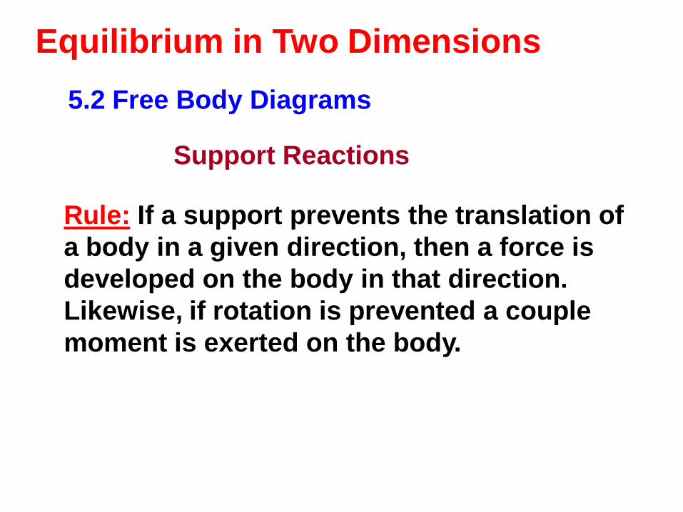
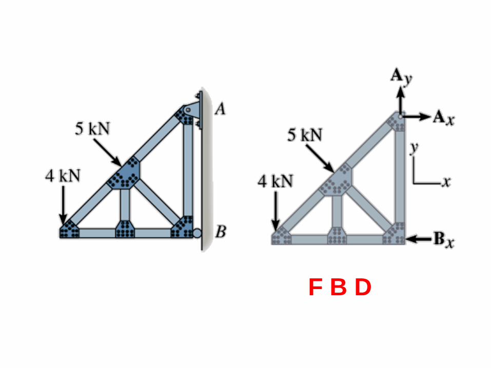
5.2 Free Body Diagrams
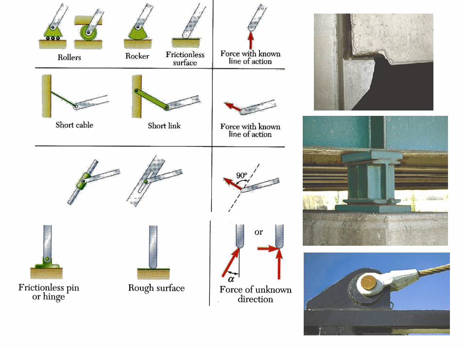
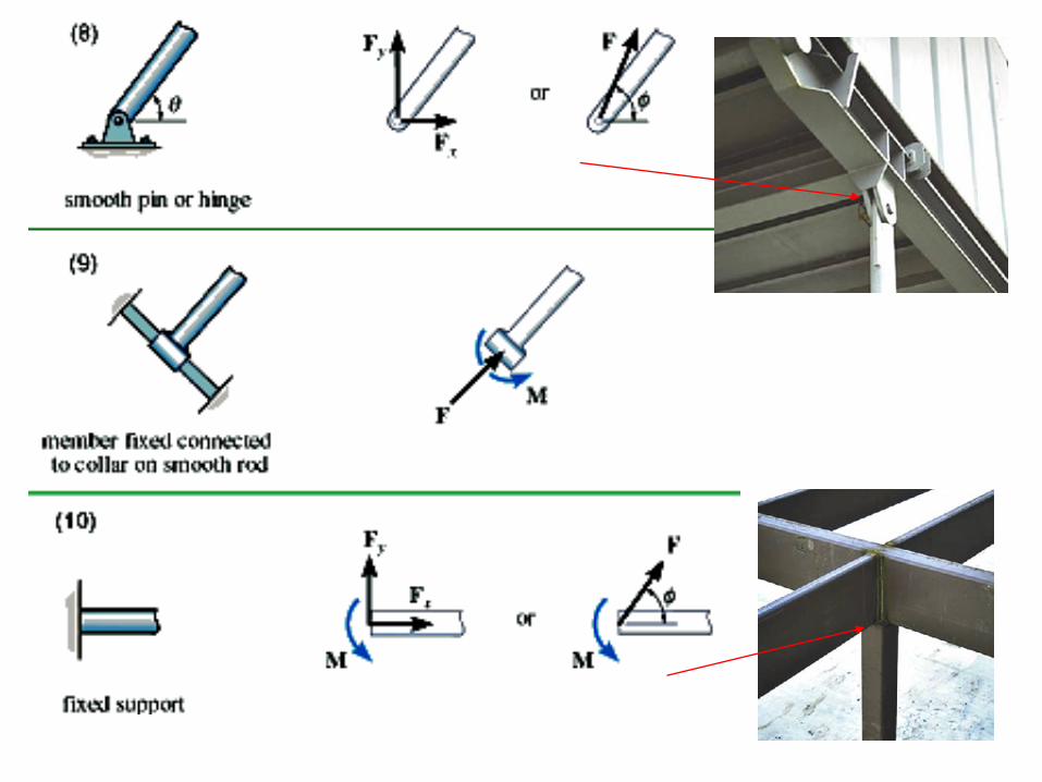
Support Reactions
Rule: If a support prevents the translation of
a body in a given direction, then a force is
developed on the body in that direction.
Likewise, if rotation is prevented a couple
moment is exerted on the body.


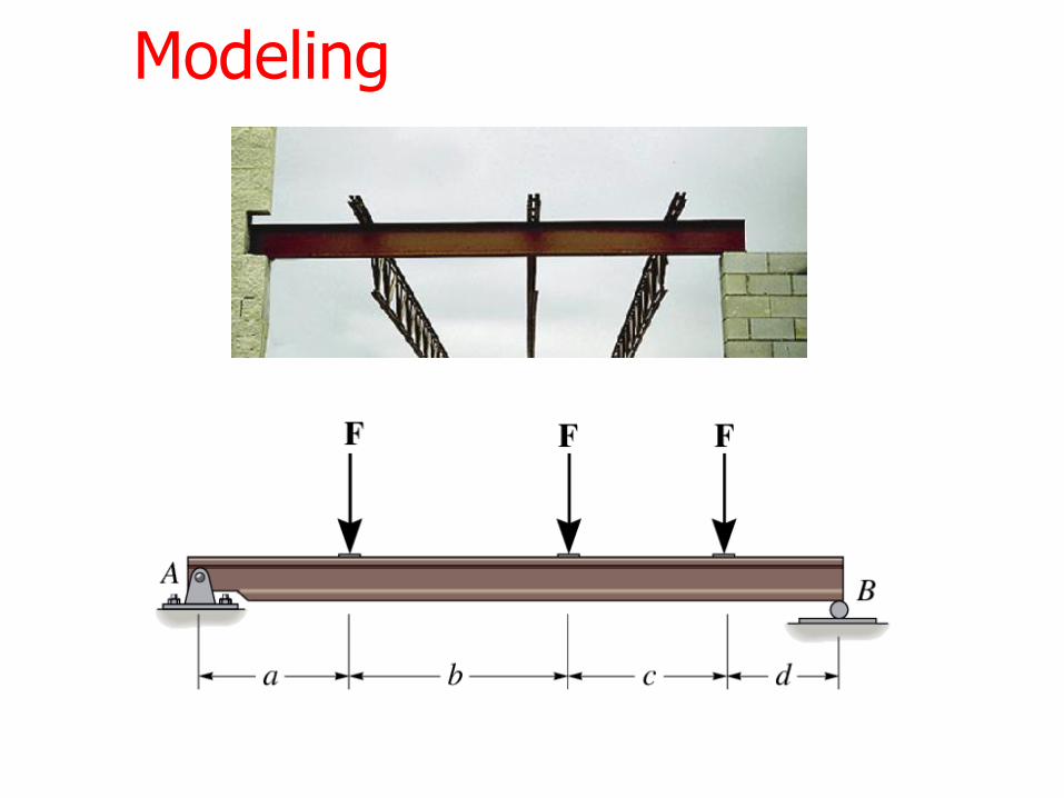
Modeling
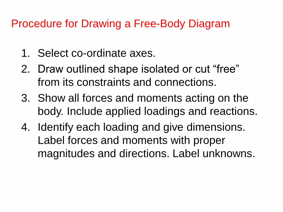
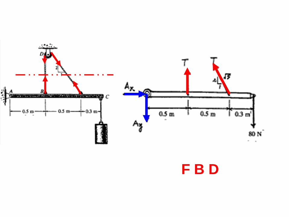
Procedure for Drawing a Free-Body Diagram
1. Select co-ordinate axes.
2. Draw outlined shape isolated or cut “free”
from its constraints and connections.
3. Show all forces and moments acting on the
body. Include applied loadings and reactions.
4. Identify each loading and give dimensions.
Label forces and moments with proper
magnitudes and directions. Label unknowns.
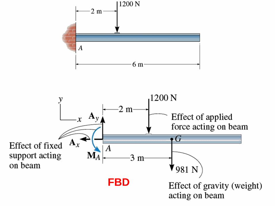
FBD

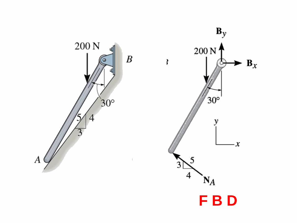
F B D

F B D

F B D
F B D
F B D
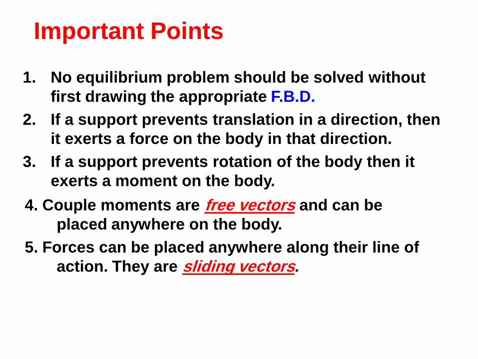
Important Points
1. No equilibrium problem should be solved without
first drawing the appropriate F.B.D.
2. If a support prevents translation in a direction, then
it exerts a force on the body in that direction.
3. If a support prevents rotation of the body then it
exerts a moment on the body.
4. Couple moments are free vectors and can be
placed anywhere on the body.
5. Forces can be placed anywhere along their line of
action. They are sliding vectors.

5.3 Equilibrium of a Rigid Body in Two
Dimensions
• Equations of equilibrium become
where A is any point in the plane of the structure.
• The 3 equations can be solved for no more than 3
unknowns.
• The 3 equations can not be augmented with additional
equations, but they can be replaced with:
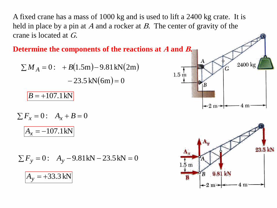
A fixed crane has a mass of 1000 kg and is used to lift a 2400 kg crate. It is
held in place by a pin at A and a rocker at B. The center of gravity of the
crane is located at G.
Determine the components of the reactions at A and B.
0m6kN5.23
m2kN81.9m5.1:0
BM A
kN1.107B
0:0 BAF xx
kN1.107xA
0kN5.23kN81.9:0 yy AF
kN 3.33yA


The frame supports part of the roof of a small building. The tension in the
cable is 150 kN.
Determine the reaction at the fixed end E.
0kN1505.7
5.4:0 xx EF
kN 0.90xE
0kN1505.7
6kN204:0 yy EF
kN 200yE
:0EM
0m5.4kN1505.7
6
m8.1kN20m6.3kN20
m4.5kN20m7.2kN20
EM
mkN0.180 EM
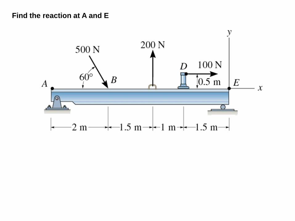
Find the reaction at A and E

Find the reactions

F2 F3
F1
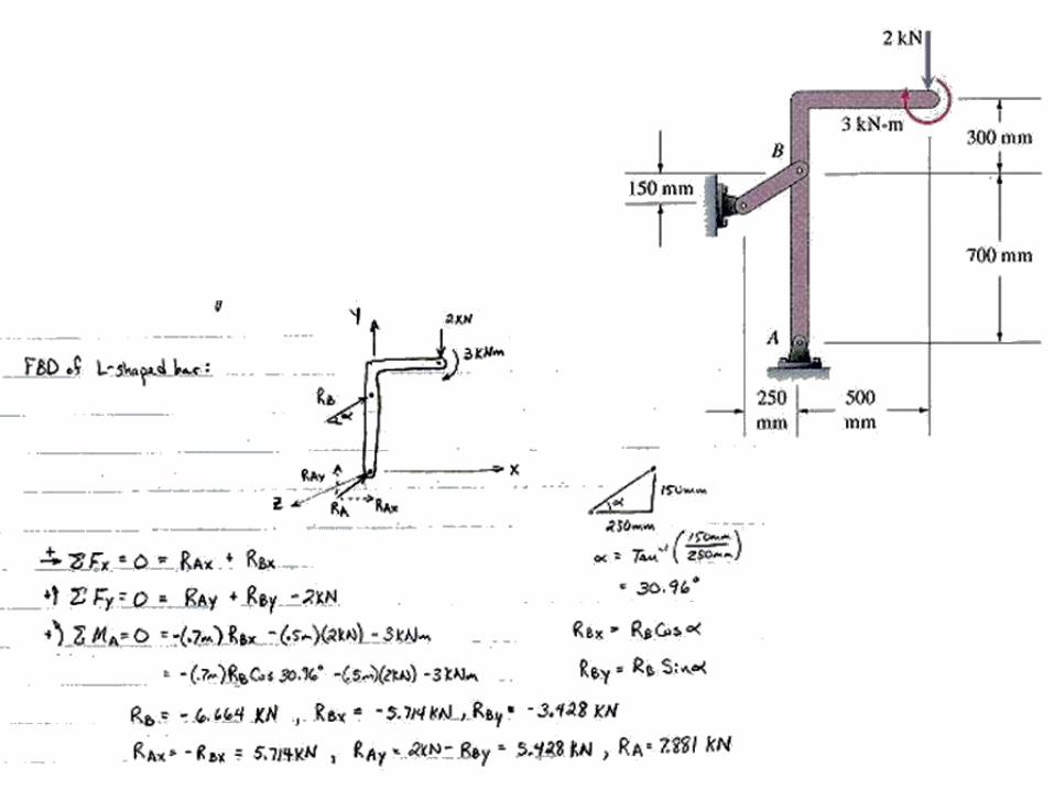
Find the Reactions
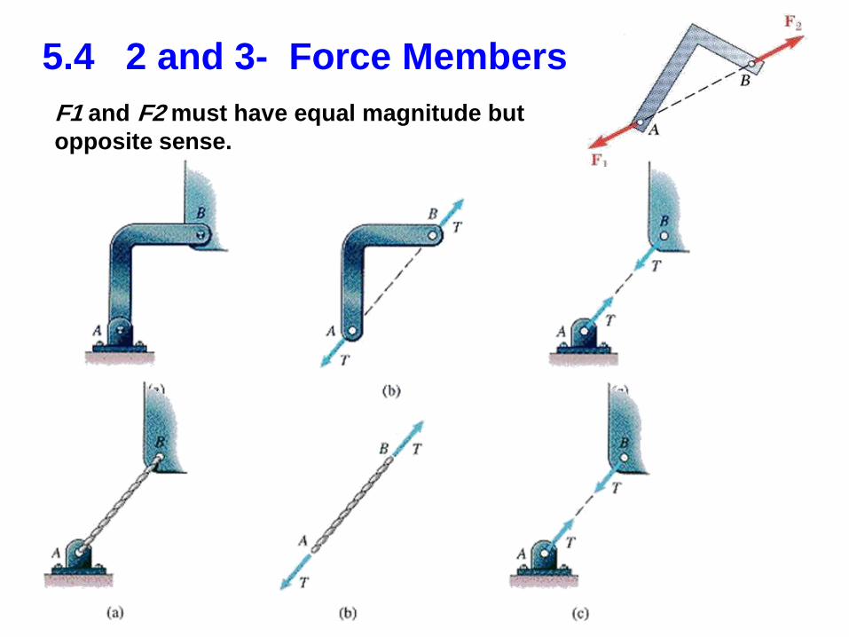
5.4 2 and 3- Force Members
F1 and F2 must have equal magnitude but
opposite sense.
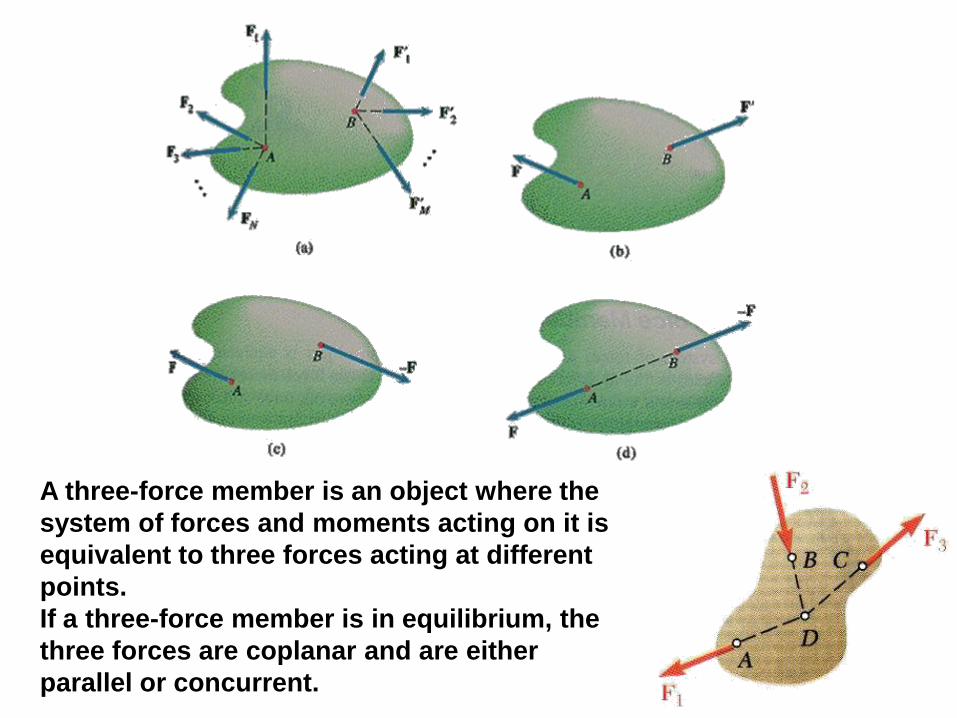
A three-force member is an object where the
system of forces and moments acting on it is
equivalent to three forces acting at different
points.
If a three-force member is in equilibrium, the
three forces are coplanar and are either
parallel or concurrent.
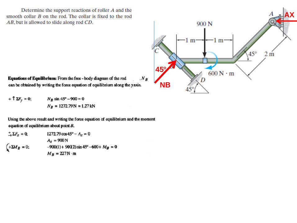
45
NB
AX
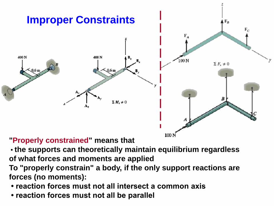
"Properly constrained" means that
• the supports can theoretically maintain equilibrium regardless
of what forces and moments are applied
To "properly constrain" a body, if the only support reactions are
forces (no moments):
• reaction forces must not all intersect a common axis
• reaction forces must not all be parallel
Improper Constraints

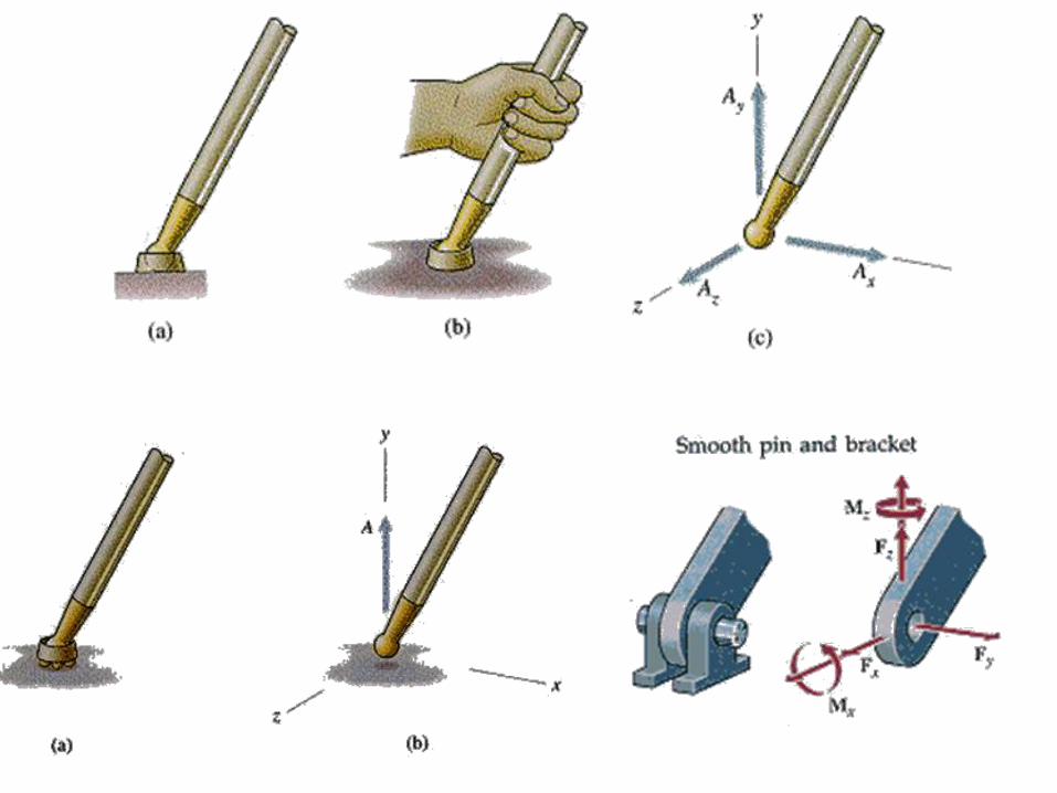
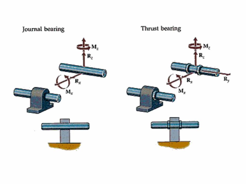
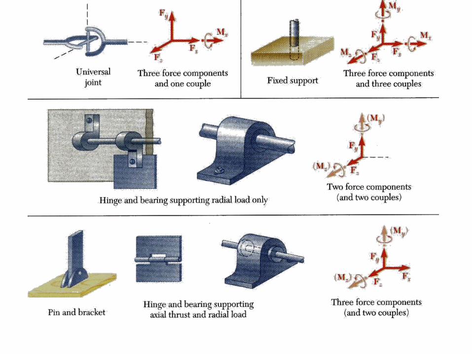
5.5 Equilibrium in 3D Reactions