Embed Size (px)
Citation preview
Spring 2018
Lecture 28
Exam Review
Statics - TAM 210 & TAM 211
AnnouncementsConcept Inventory: Ungraded assessment of course knowledge
Extra credit: Complete #1 or #2 for 0.5 out of 100 pt of final grade each, or both for 1.5 out of 100 pt of final grade
#2: Sign up at CBTF (4/2-4 M-Th) 50 min appointment, should take < 30 min
Upcoming deadlines:
Friday (3/30) Last lecture for TAM 210 students
Monday (4/2) PL HW 9/11 ME Tutorial due for TAM 211 students Lecture 29 for TAM 211 students
Discussion section for (4/3-4/4) Attendance taken for TAM 211, no worksheet TA/CA answer questions about course material TAM 210 students may attend
Written exam
Comprehensive from Lecture 1 through Lecture 27 (Chapters 1 -8)
Thursday 4/5, 7-9pm
TAM 210 students: 100 Material Science & Engineering Building (MSEB) Do not confuse this building with Mechanical Engineering Building (MEB)
TAM 211 students: 100 Noyes Lab
Bring i-Card and pencil
No calculators
Closed book, closed notes
Conflict exam & DRES accommodation exam: Prof. H-W is not taking anymore requests
Composition of exam:
A. (60 points) Short-answer using Scantron (must use pencil!)
B. (40 points) Written answers on exam paper (NO need for blue exam booklet)
C. Multiple variations of the exam
Course Overview
Description: In this course, we will cover fundamental concepts
that are used in every engineering discipline. We will begin with
forces, moments and move towards structural analyses of frames,
devices, and machines. By the end, you will be able to solve rigid
body mechanics problems that will inform the design of everything
from bridges to biomedical devices.
Big Idea: Clear knowledge of external forces (boundary
conditions) is required to determine what constraints are necessary
for the safe (static equilibrium) development and design of any
widget. Free body diagrams are an essential tool for understanding
the forces and moments on a body.
Resources:
PrairieLearn: All past HW questions can be reviewed and
reworked
Mastering Engineering: Extra practice and study material
available under Menu>"Study Area", then "Additional
Problems" under the menu of the new window
• Problems organized by book chapters
• Chose topic of interest from drop down menu near top
Chapter 1: General Principles
Chapter 2: Force Vectors
Chapter 3: Equilibrium of a particle
Chapter 4: Force System Resultants
Chapter 5: Equilibrium of Rigid Bodies
Chapter 6: Structural Analysis
Chapter 7: Internal Forces
Chapter 8: Friction
Chapter 1: General Principles
Chapter 1: General Principles Main goals and learning objectives
Introduce the basic ideas of Mechanics
Give a concise statement of Newton’s laws of motion and gravitation
Review the principles for applying the SI system of units
Examine standard procedures for performing numerical calculations
Outline a general guide for solving problems
General procedure for analysis
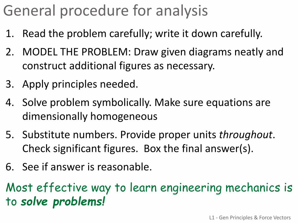
1. Read the problem carefully; write it down carefully.
2. MODEL THE PROBLEM: Draw given diagrams neatly and construct additional figures as necessary.
3. Apply principles needed.
4. Solve problem symbolically. Make sure equations are dimensionally homogeneous
5. Substitute numbers. Provide proper units throughout. Check significant figures. Box the final answer(s).
6. See if answer is reasonable.
Most effective way to learn engineering mechanics is to solve problems!
L1 - Gen Principles & Force Vectors
Chapter 2: Force Vectors
Chapter 2: Force vectorsMain goals and learning objectives
Define scalars, vectors and vector operations and use them to analyze forces acting on objects
Add forces and resolve them into components
Express force and position in Cartesian vector form
Determine a vector’s magnitude and direction
Introduce the unit vector and position vector
Introduce the dot product and use it to find the angle between two vectors or the projection of one vector onto another
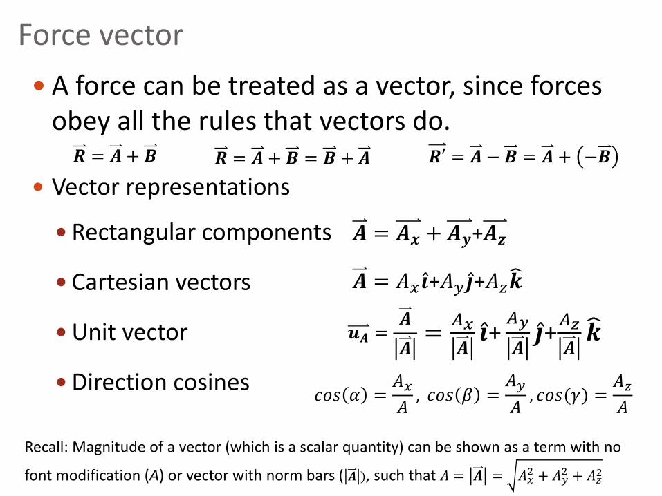
Force vector
A force can be treated as a vector, since forces obey all the rules that vectors do.
Vector representations
Rectangular components
Cartesian vectors
Unit vector
Direction cosines
𝑨 = 𝑨𝒙 + 𝑨𝒚+𝑨𝒛
𝑨 = 𝐴𝑥 Ƹ𝒊+𝐴𝑦 Ƹ𝒋+𝐴𝑧𝒌
𝒖𝑨 =𝑨
𝑨=
𝐴𝑥
𝑨Ƹ𝒊+𝐴𝑦
𝑨Ƹ𝒋+𝐴𝑧
𝑨𝒌
Recall: Magnitude of a vector (which is a scalar quantity) can be shown as a term with no
font modification (A) or vector with norm bars ( 𝑨 ), such that 𝐴 = 𝑨 = 𝐴𝑥2 + 𝐴𝑦
2 + 𝐴𝑧2
𝑐𝑜𝑠 𝛼 =𝐴𝑥𝐴, 𝑐𝑜𝑠 𝛽 =
𝐴𝑦
𝐴, 𝑐𝑜𝑠(𝛾) =
𝐴𝑧𝐴
𝑹 = 𝑨 + 𝑩 𝑹′ = 𝑨 − 𝑩 = 𝑨 + −𝑩𝑹 = 𝑨 + 𝑩 = 𝑩 + 𝑨
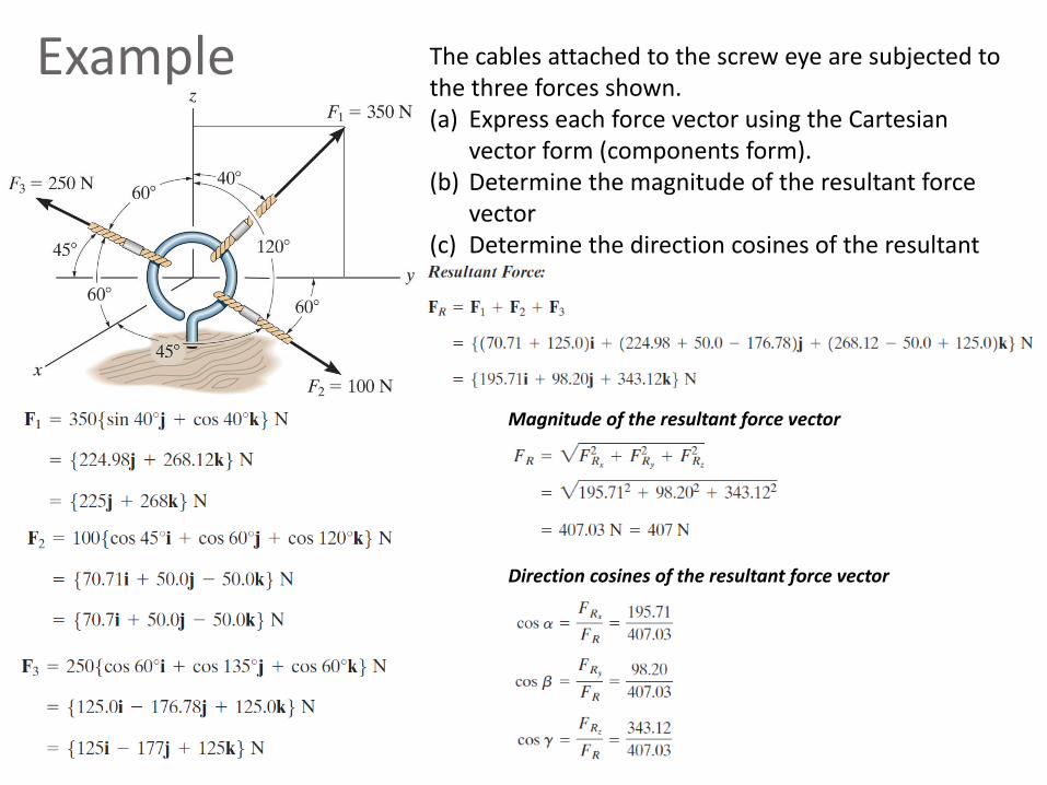
Example The cables attached to the screw eye are subjected to the three forces shown.(a) Express each force vector using the Cartesian
vector form (components form).(b) Determine the magnitude of the resultant force
vector(c) Determine the direction cosines of the resultant
force vector
Magnitude of the resultant force vector
Direction cosines of the resultant force vector
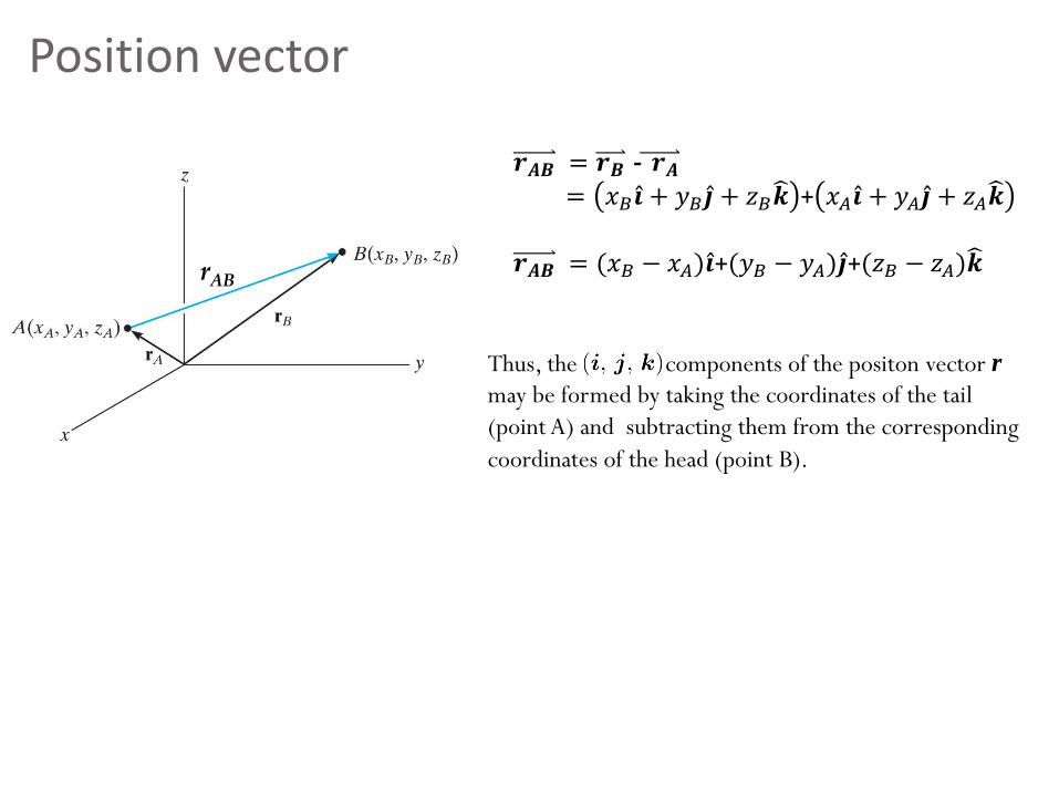
Position vector
Thus, the components of the positon vector r
may be formed by taking the coordinates of the tail
(point A) and subtracting them from the corresponding
coordinates of the head (point B).
rAB
𝒓𝑨𝑩 = 𝒓𝑩 - 𝒓𝑨= 𝑥𝐵 Ƹ𝒊 + 𝑦𝐵 Ƹ𝒋 + 𝑧𝐵𝒌 + 𝑥𝐴 Ƹ𝒊 + 𝑦𝐴 Ƹ𝒋 + 𝑧𝐴𝒌
𝒓𝑨𝑩 = (𝑥𝐵 − 𝑥𝐴) Ƹ𝒊+(𝑦𝐵 − 𝑦𝐴) Ƹ𝒋+(𝑧𝐵 − 𝑧𝐴)𝒌
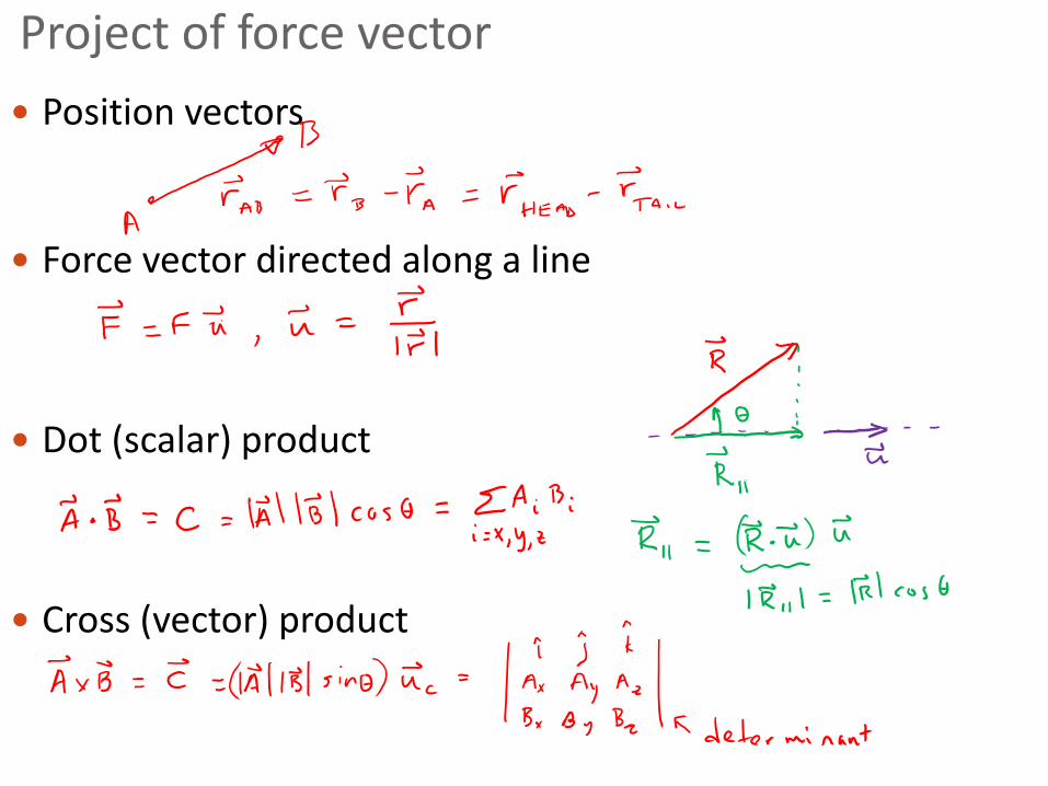
Project of force vector
Position vectors
Force vector directed along a line
Dot (scalar) product
Cross (vector) product
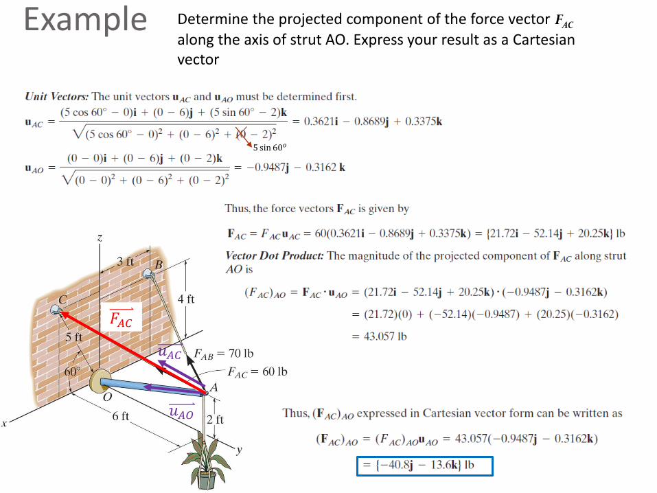
Example Determine the projected component of the force vector FAC
along the axis of strut AO. Express your result as a Cartesian vector
5 sin 60𝑜
𝑢𝐴𝐶
𝑢𝐴𝑂
𝐹𝐴𝐶
Chapter 3: Equilibrium of a particle
Goals and Objectives
• Practice following general procedure for analysis.
• Introduce the concept of a free-body diagram for an object modeled as a particle.
• Solve equilibrium problems using the equations of equilibrium.• 3D, 2D planar, idealizations (smooth surfaces, pulleys,
springs)
Free body diagramDrawing of a body, or part of a body, on which all forces acting on the body are shown.• Key to writing the equations of equilibrium.• Can draw for any object/subsystem of system. Pick the most
appropriate object. (Equal & opposite forces on interacting bodies.)
Draw Outlined Shape: image object free of its surroundings Sometimes may collapse large object into point mass
Establish x, y, z axes in any suitable orientation Show positive directions for translation and rotation
Show all forces acting on the object at points of application Label all known and unknown forces Sense (“direction”) of unknown force can be assumed. If
solution is negative, then the sense is reverse of that shown on FBD
Equations of equilibrium Use FBD to write equilibrium equations in x, y, z directions
Σ 𝑭𝒙 = 0, Σ 𝑭𝒚 = 0, and if 3D Σ 𝑭𝒛 = 0,
If # equations ≥ # unknown forces, statically determinate (can solve for unknowns)
If # equations < # unknown forces, indeterminate (can NOT solve for unknowns), need more equations
Get more equations from FBD of other bodies in the problem
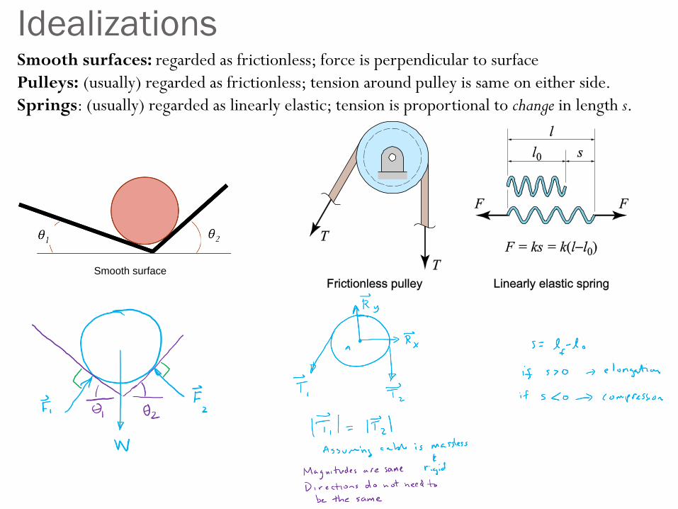
IdealizationsSmooth surfaces: regarded as frictionless; force is perpendicular to surface
Pulleys: (usually) regarded as frictionless; tension around pulley is same on either side.
Springs: (usually) regarded as linearly elastic; tension is proportional to change in length s.
Smooth surface
A
B
C
D
(1)
(2)
(3)
(4)(5)
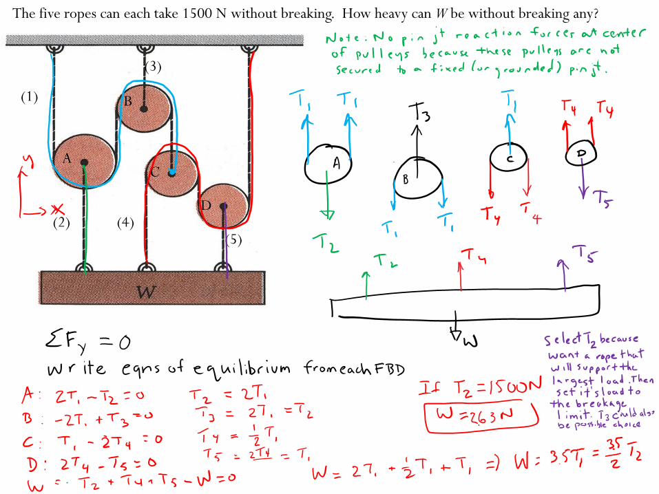
The five ropes can each take 1500 N without breaking. How heavy can W be without breaking any?
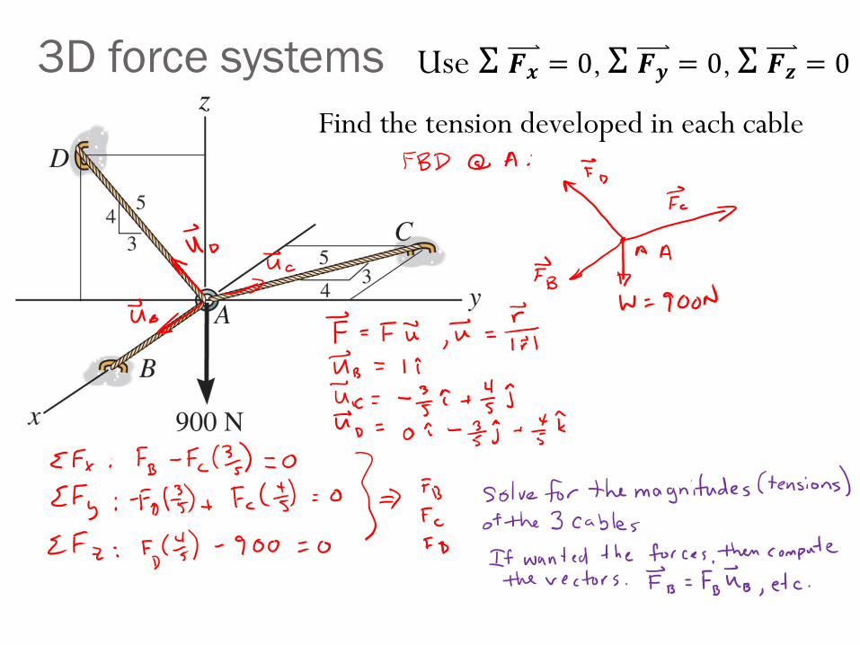
3D force systems
Find the tension developed in each cable
Use Σ 𝑭𝒙 = 0, Σ 𝑭𝒚 = 0, Σ 𝑭𝒛 = 0
Chapter 4: Force System Resultants
Goals and Objectives
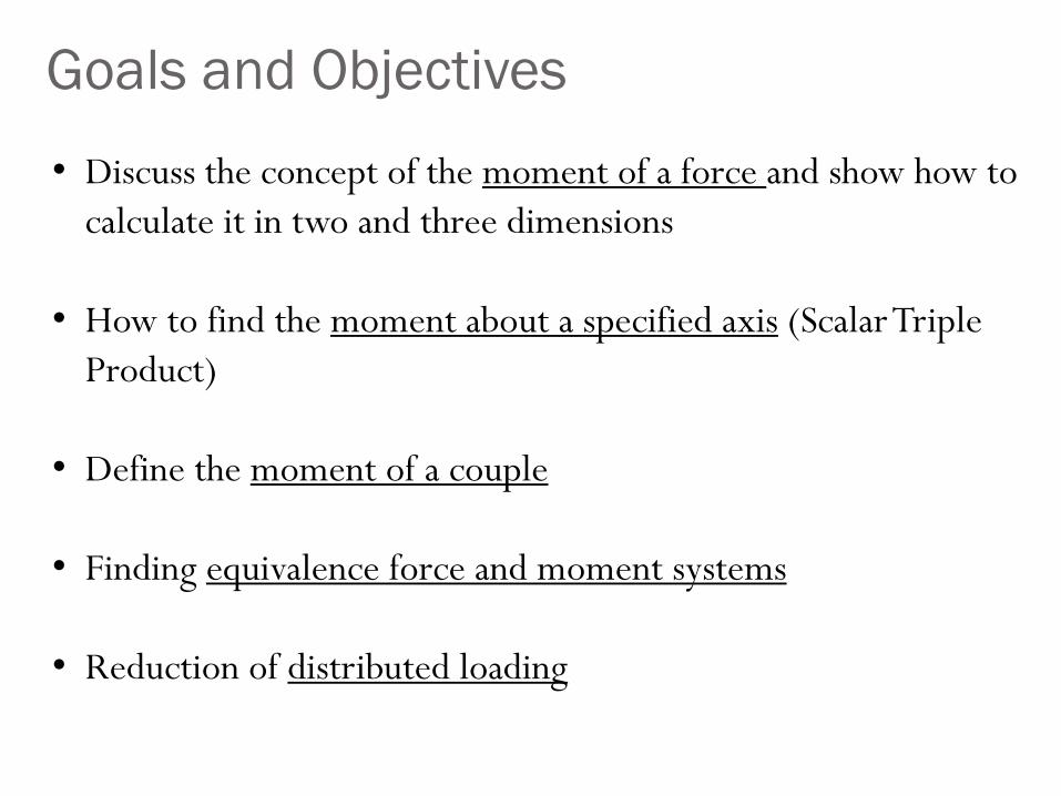
• Discuss the concept of the moment of a force and show how to
calculate it in two and three dimensions
• How to find the moment about a specified axis (Scalar Triple
Product)
• Define the moment of a couple
• Finding equivalence force and moment systems
• Reduction of distributed loading
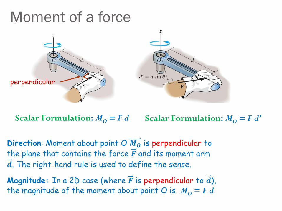
Moment of a force
perpendicular
Scalar Formulation: MO = F d Scalar Formulation: MO = F d’
Direction: Moment about point O 𝑴𝑶 is perpendicular to the plane that contains the force 𝑭 and its moment arm
𝒅. The right-hand rule is used to define the sense.
Magnitude: In a 2D case (where 𝑭 is perpendicular to 𝒅), the magnitude of the moment about point O is MO = F d

Moment of a force
Vector Formulation
Use cross product: 𝑴𝑂 = 𝒓 × 𝑭
Direction: Defined by right hand rule.
𝑴𝑂 = 𝒓 × 𝑭 =
Ƹ𝒊 Ƹ𝒋 𝒌𝑟𝑥 𝑟𝑦 𝑟𝑧𝐹𝑥 𝐹𝑦 𝐹𝑧
= 𝑟𝑦𝐹𝑧 − 𝑟𝑧𝐹𝑦 Ƹ𝒊 − 𝑟𝑥𝐹𝑧 − 𝑟𝑧𝐹𝑥 Ƹ𝒋 + 𝑟𝑥𝐹𝑦 − 𝑟𝑦𝐹𝑥 𝒌
Magnitude:
MO = 𝑴𝑂 = 𝒓 𝑭 𝑠𝑖𝑛𝜃 = 𝐹 𝑟𝑠𝑖𝑛𝜃 = 𝐹𝑑
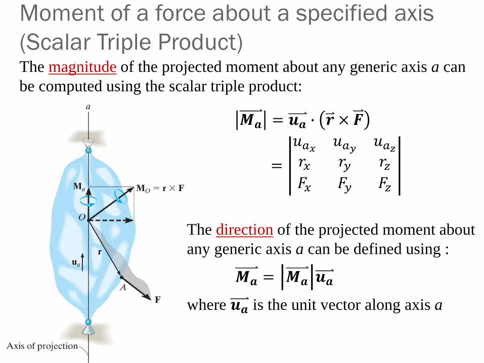
Moment of a force about a specified axis
(Scalar Triple Product)The magnitude of the projected moment about any generic axis a can
be computed using the scalar triple product:
𝑴𝒂 = 𝒖𝒂 ∙ 𝒓 × 𝑭
=
𝑢𝑎𝑥 𝑢𝑎𝑦 𝑢𝑎𝑧𝑟𝑥 𝑟𝑦 𝑟𝑧𝐹𝑥 𝐹𝑦 𝐹𝑧
The direction of the projected moment about
any generic axis a can be defined using :
𝑴𝒂 = 𝑴𝒂 𝒖𝒂
where 𝒖𝒂 is the unit vector along axis a
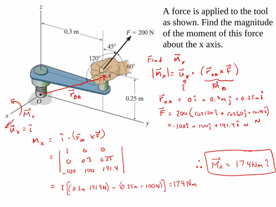
A force is applied to the tool
as shown. Find the magnitude
of the moment of this force
about the x axis.
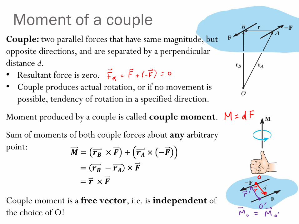
Moment of a coupleCouple: two parallel forces that have same magnitude, but
opposite directions, and are separated by a perpendicular
distance d.
• Resultant force is zero.
• Couple produces actual rotation, or if no movement is
possible, tendency of rotation in a specified direction.
Moment produced by a couple is called couple moment.
Sum of moments of both couple forces about any arbitrary
point:
Couple moment is a free vector, i.e. is independent of
the choice of O!
𝑴 = 𝒓𝑩 × 𝑭 + 𝒓𝑨 × −𝑭
= 𝒓𝑩 − 𝒓𝑨 × 𝑭
= 𝒓 × 𝑭
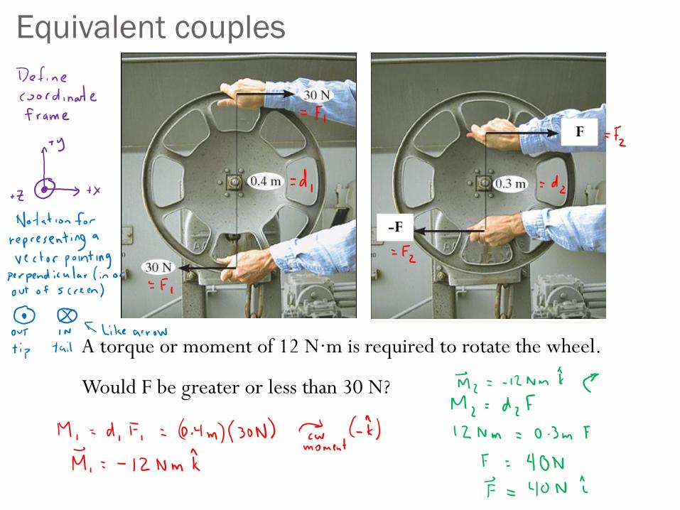
A torque or moment of 12 N·m is required to rotate the wheel.
Would F be greater or less than 30 N?
F
-F
Equivalent couples
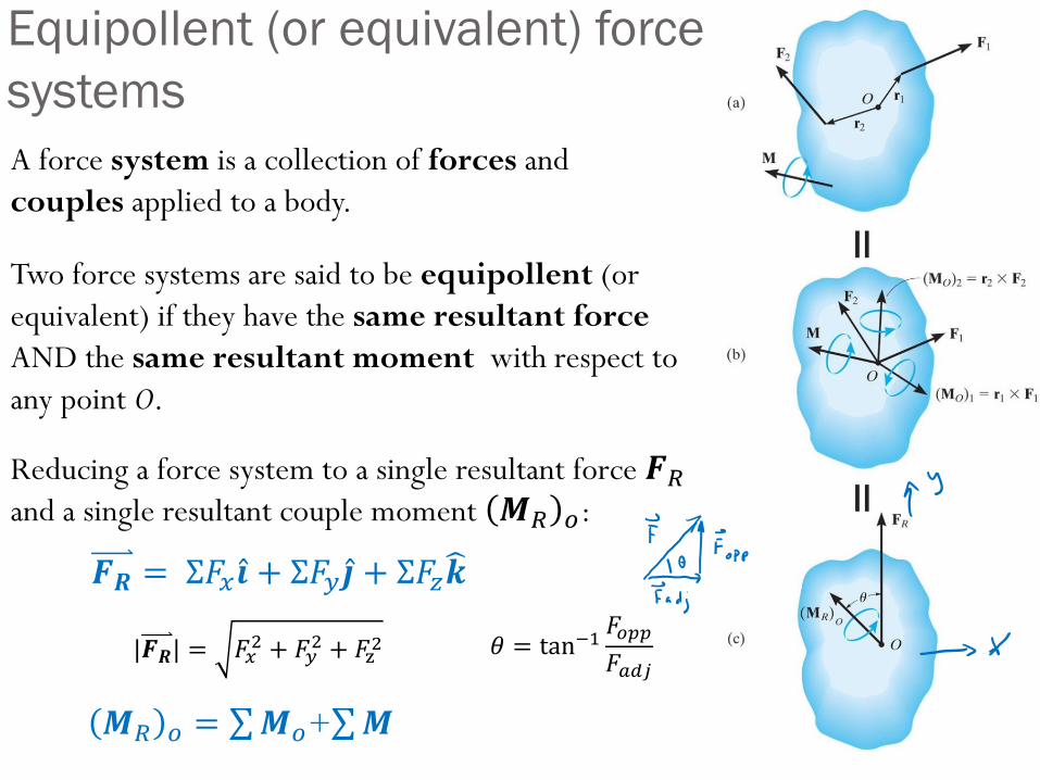
A force system is a collection of forces and
couples applied to a body.
Two force systems are said to be equipollent (or
equivalent) if they have the same resultant force
AND the same resultant moment with respect to
any point O.
Reducing a force system to a single resultant force 𝑭𝑅and a single resultant couple moment 𝑴𝑅 𝑜:
Equipollent (or equivalent) force
systems
𝑴𝑅 𝑜 = σ𝑴𝑜+σ𝑴
𝑭𝑹 = Σ𝐹𝑥 Ƹ𝒊 + Σ𝐹𝑦 Ƹ𝒋 + Σ𝐹𝑧𝒌
|𝑭𝑹| = 𝐹𝑥2 + 𝐹𝑦
2 + 𝐹z2 𝜃 = tan−1
𝐹𝑜𝑝𝑝
𝐹𝑎𝑑𝑗
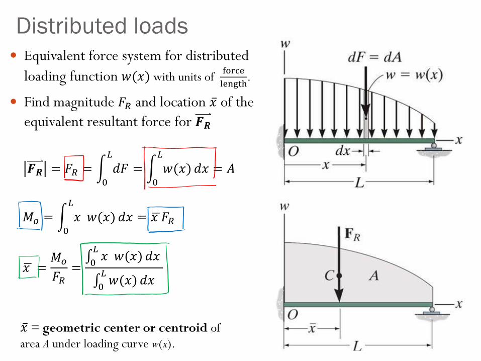
Equivalent force system for distributed
loading function 𝑤(𝑥) with units of force
length.
Find magnitude 𝐹𝑅 and location ҧ𝑥 of the
equivalent resultant force for 𝑭𝑹
Distributed loads
𝑭𝑹 = 𝐹𝑅 = න0
𝐿
𝑑𝐹 = න0
𝐿
𝑤(𝑥) 𝑑𝑥 = 𝐴
𝑀𝑜 = න0
𝐿
𝑥 𝑤(𝑥) 𝑑𝑥 = ഥ𝑥 𝐹𝑅
ഥ𝑥 =𝑀𝑜
𝐹𝑅=0𝐿𝑥 𝑤(𝑥) 𝑑𝑥
0𝐿𝑤(𝑥) 𝑑𝑥
ҧ𝑥 = geometric center or centroid of
area A under loading curve w(x).
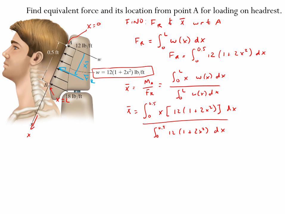
Find equivalent force and its location from point A for loading on headrest.
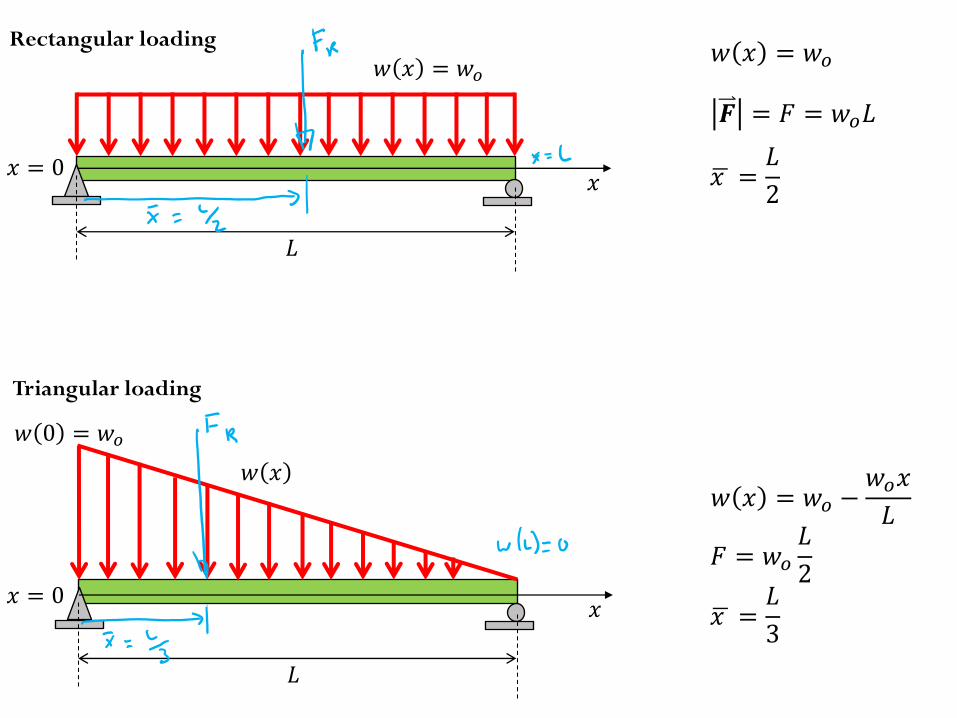
Rectangular loading
𝐿
𝑤 𝑥 = 𝑤𝑜
𝑥
𝐹 = 𝑤𝑜
𝐿
2
ഥ𝑥 =𝐿
3
𝑤 𝑥 = 𝑤𝑜 −𝑤𝑜𝑥
𝐿
𝑭 = 𝐹 = 𝑤𝑜𝐿
ഥ𝑥 =𝐿
2
𝑤 𝑥 = 𝑤𝑜
𝑥 = 0
Triangular loading
𝑤 𝑥
𝑤 0 = 𝑤𝑜
𝐿
𝑥𝑥 = 0
Focus on 2D problems
Sections 5.1-5.4, 5.7
TAM 211 students will cover 3D problems (sections 5.5-5.6) in week 13
Chapter 5: Equilibrium of Rigid
Bodies
Introduce the free-body diagram for a 2D rigid body
Develop the equations of equilibrium for a 2D rigid body
Solve 2D rigid body equilibrium problems using the equations
of equilibrium
Introduce concepts of
Support reactions
Two- and three-force members
Constraints and statical determinacy
Goals and Objectives
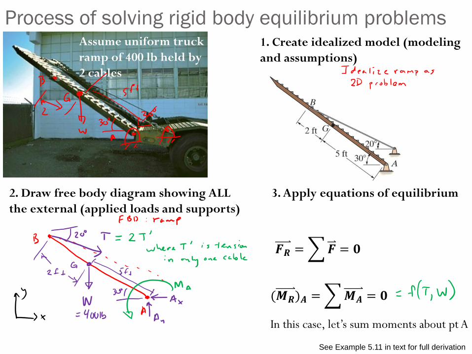
Process of solving rigid body equilibrium problems1. Create idealized model (modeling
and assumptions)
2. Draw free body diagram showing ALL
the external (applied loads and supports)
3. Apply equations of equilibrium
𝑭𝑹 =𝑭 = 𝟎
(𝑴𝑹)𝑨 =𝑴𝑨 = 𝟎
In this case, let’s sum moments about pt A
See Example 5.11 in text for full derivation
Assume uniform truck
ramp of 400 lb held by
2 cables
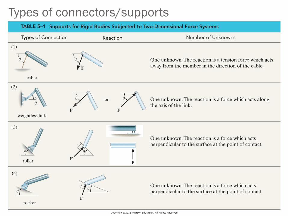
Types of connectors/supports
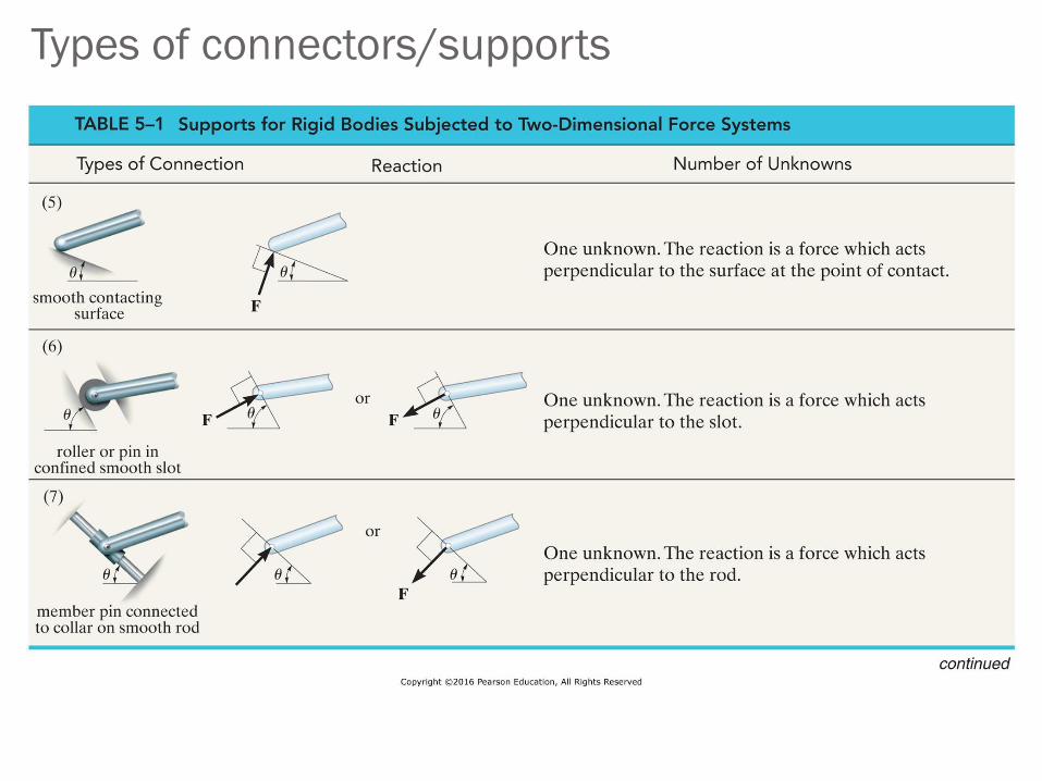
Types of connectors/supports
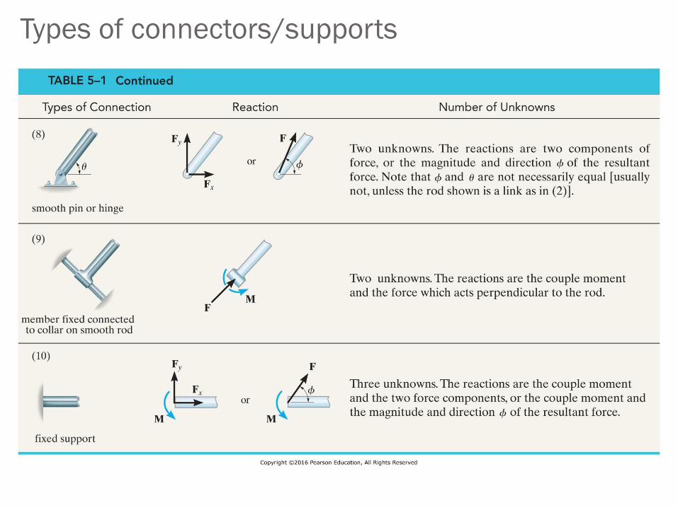
Types of connectors/supports
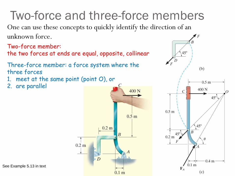
Two-force and three-force membersOne can use these concepts to quickly identify the direction of an
unknown force.
Two-force member: the two forces at ends are equal, opposite, collinear
Three-force member: a force system where the three forces 1. meet at the same point (point O), or2. are parallel
See Example 5.13 in text
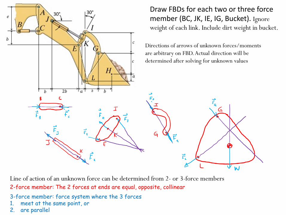
Draw FBDs for each two or three force member (BC, JK, IE, IG, Bucket). Ignore
weight of each link. Include dirt weight in bucket.
Directions of arrows of unknown forces/moments
are arbitrary on FBD. Actual direction will be
determined after solving for unknown values
Line of action of an unknown force can be determined from 2- or 3-force members
2-force member: The 2 forces at ends are equal, opposite, collinear
3-force member: force system where the 3 forces 1. meet at the same point, or2. are parallel
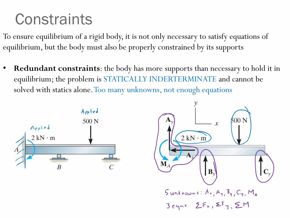
ConstraintsTo ensure equilibrium of a rigid body, it is not only necessary to satisfy equations of
equilibrium, but the body must also be properly constrained by its supports
• Redundant constraints: the body has more supports than necessary to hold it in
equilibrium; the problem is STATICALLY INDERTERMINATE and cannot be
solved with statics alone. Too many unknowns, not enough equations
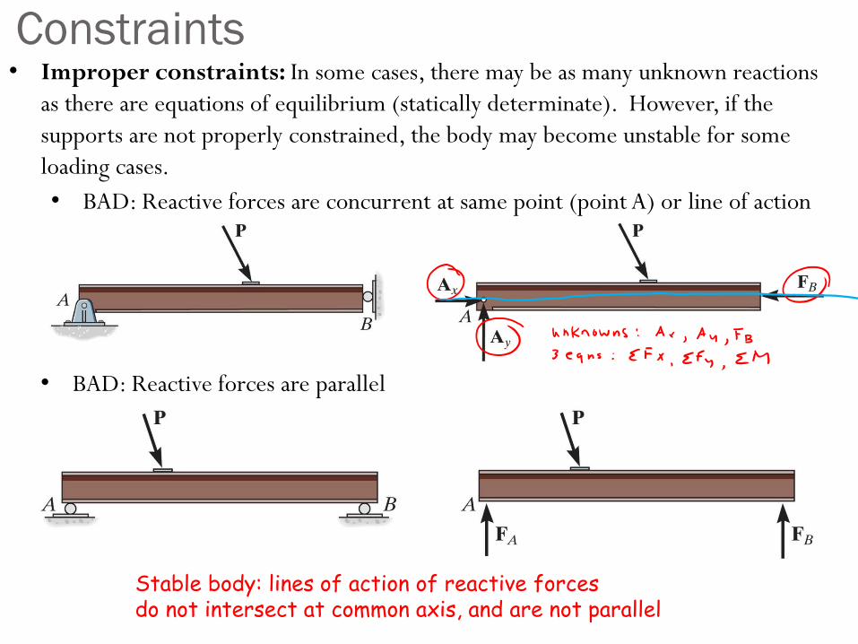
Constraints• Improper constraints: In some cases, there may be as many unknown reactions
as there are equations of equilibrium (statically determinate). However, if the
supports are not properly constrained, the body may become unstable for some
loading cases.
• BAD: Reactive forces are parallel
• BAD: Reactive forces are concurrent at same point (point A) or line of action
Stable body: lines of action of reactive forces do not intersect at common axis, and are not parallel
Chapter 6: Structural Analysis
Goals and Objectives• Determine the forces in members of a truss using the method of
joints
• Determine zero-force members
• Determine the forces in members of a truss using the method of
sections
• Determine the forces and moments in members of a frame or
machine
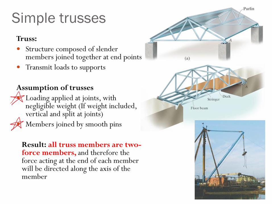
Truss:
Structure composed of slender members joined together at end points
Transmit loads to supports
Assumption of trusses
Loading applied at joints, with negligible weight (If weight included, vertical and split at joints)
Members joined by smooth pins
Result: all truss members are two-force members, and therefore the force acting at the end of each member will be directed along the axis of the member
Simple trusses
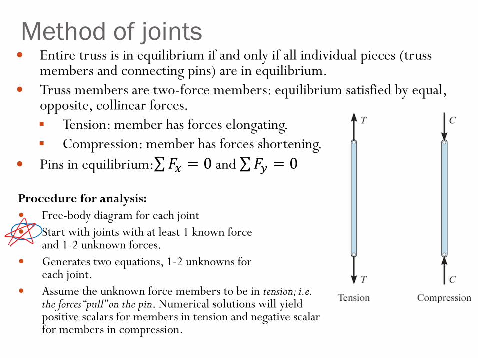
Method of joints Entire truss is in equilibrium if and only if all individual pieces (truss
members and connecting pins) are in equilibrium.
Truss members are two-force members: equilibrium satisfied by equal, opposite, collinear forces.
Tension: member has forces elongating.
Compression: member has forces shortening.
Pins in equilibrium:σ𝐹𝑥 = 0 and σ𝐹𝑦 = 0
Procedure for analysis:
Free-body diagram for each joint
Start with joints with at least 1 known forceand 1-2 unknown forces.
Generates two equations, 1-2 unknowns for each joint.
Assume the unknown force members to be in tension; i.e. the forces “pull” on the pin. Numerical solutions will yield positive scalars for members in tension and negative scalar for members in compression.
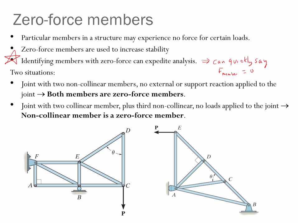
• Particular members in a structure may experience no force for certain loads.
• Zero-force members are used to increase stability
• Identifying members with zero-force can expedite analysis.
Two situations:
• Joint with two non-collinear members, no external or support reaction applied to the
joint Both members are zero-force members.
• Joint with two collinear member, plus third non-collinear, no loads applied to the joint
Non-collinear member is a zero-force member.
Zero-force members
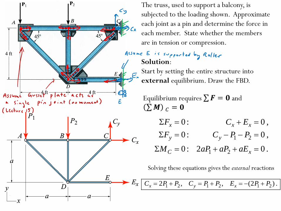
The truss, used to support a balcony, is
subjected to the loading shown. Approximate
each joint as a pin and determine the force in
each member. State whether the members
are in tension or compression.
Solution:
Start by setting the entire structure into
external equilibrium. Draw the FBD.
1 2
1 2
0 : 0 ,
0 : 0 ,
0 : 2 0 .
x x x
y y
C x
F C E
F C P P
M aP aP aE
1 2 1 2 1 22 , , (2 ) .x y xC P P C P P E P P
Solving these equations gives the external reactions
Equilibrium requires σ𝑭 = 𝟎 and σ𝑴 𝐶 = 𝟎
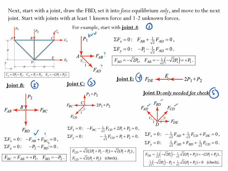
Next, start with a joint, draw the FBD, set it into force equilibrium only, and move to the next
joint. Start with joints with at least 1 known force and 1-2 unknown forces.
1
2
11 2
0 : 0 ,
0 : 0 .
x AB AD
y AD
F F F
F P F
11 1 12
2 , 2 .AD ABF P F P P
For example, start with joint A:
Joint B:
2
0 : 0 ,
0 : 0 .
x AB BC
y BD
F F F
F P F
1 2, .BC AB BDF F P F P
Joint C:
11 22
11 22
0 : 2 0 ,
0 : 0 .
x BC CD
y CD
F F F P P
F F P P
1 2 1 1 2
1 2
2(2 ) 2( ) ,
2( ) (check) .
CD
CD
F P P P P P
F P P
Joint D: only needed for check
Joint E:
1 1
2 2
1 1
2 2
0 : 0 ,
0 : 0 .
x AD CD DE
y AD BD CD
F F F F
F F F F
1 11 1 2 1 22 2
1 11 2 1 22 2
2 2( ) (2 ) ,
2 2( ) 0 (check) .
DEF P P P P P
P P P P
1 2 1 2 1 22 , , (2 ) .x y xC P P C P P E P P
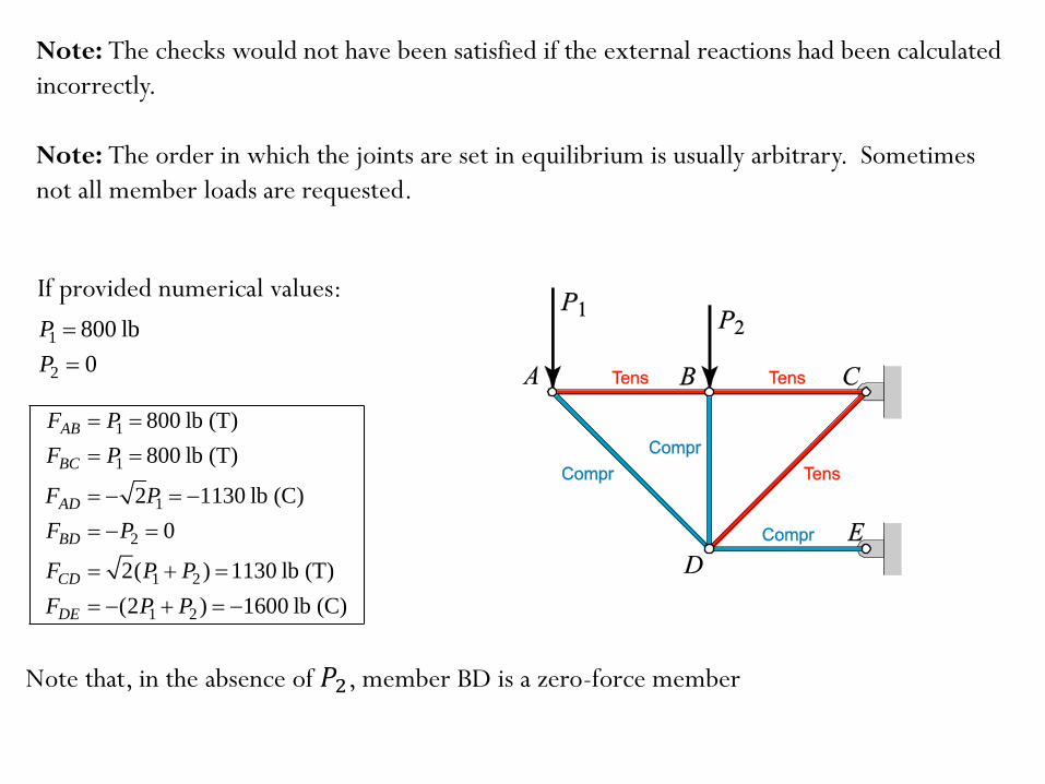
Note: The checks would not have been satisfied if the external reactions had been calculated
incorrectly.
Note: The order in which the joints are set in equilibrium is usually arbitrary. Sometimes
not all member loads are requested.
1 800 lbP
2 0P
1
1
1
2
1 2
1 2
800 lb (T)
800 lb (T)
2 1130 lb (C)
0
2( ) 1130 lb (T)
(2 ) 1600 lb (C)
AB
BC
AD
BD
CD
DE
F P
F P
F P
F P
F P P
F P P
Note that, in the absence of 𝑃2, member BD is a zero-force member
If provided numerical values:
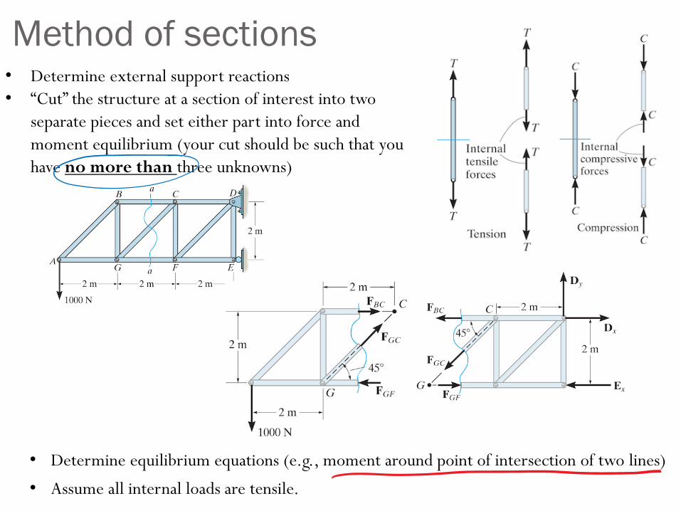
Method of sections• Determine external support reactions
• “Cut” the structure at a section of interest into two
separate pieces and set either part into force and
moment equilibrium (your cut should be such that you
have no more than three unknowns)
• Determine equilibrium equations (e.g., moment around point of intersection of two lines)
• Assume all internal loads are tensile.
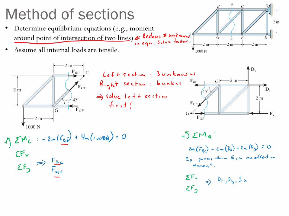
Method of sections• Determine equilibrium equations (e.g., moment
around point of intersection of two lines)
• Assume all internal loads are tensile.
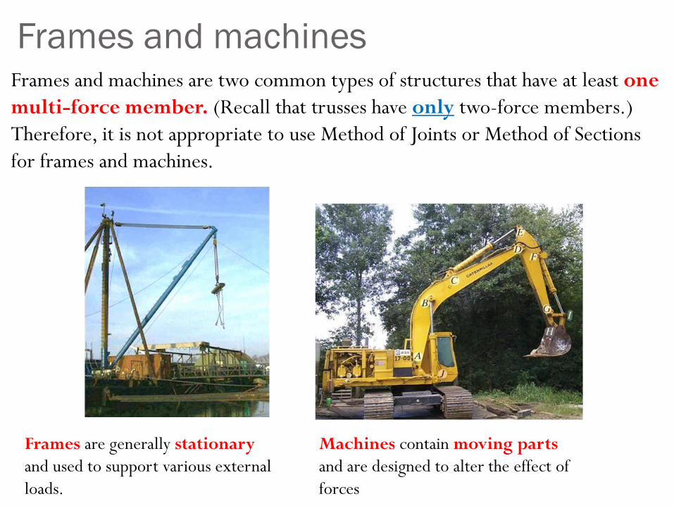
Frames and machinesFrames and machines are two common types of structures that have at least one
multi-force member. (Recall that trusses have only two-force members.)
Therefore, it is not appropriate to use Method of Joints or Method of Sections
for frames and machines.
Frames are generally stationary
and used to support various external
loads.
Machines contain moving parts
and are designed to alter the effect of
forces
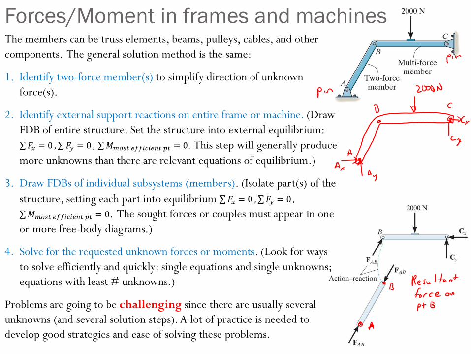
The members can be truss elements, beams, pulleys, cables, and other
components. The general solution method is the same:
1. Identify two-force member(s) to simplify direction of unknown
force(s).
2. Identify external support reactions on entire frame or machine. (Draw
FDB of entire structure. Set the structure into external equilibrium:
σ𝐹𝑥 = 0 ,σ𝐹𝑦 = 0 , σ𝑀𝑚𝑜𝑠𝑡 𝑒𝑓𝑓𝑖𝑐𝑖𝑒𝑛𝑡 𝑝𝑡 = 0. This step will generally produce
more unknowns than there are relevant equations of equilibrium.)
3. Draw FDBs of individual subsystems (members). (Isolate part(s) of the
structure, setting each part into equilibrium σ𝐹𝑥 = 0 ,σ𝐹𝑦 = 0 ,
σ𝑀𝑚𝑜𝑠𝑡 𝑒𝑓𝑓𝑖𝑐𝑖𝑒𝑛𝑡 𝑝𝑡 = 0. The sought forces or couples must appear in one
or more free-body diagrams.)
4. Solve for the requested unknown forces or moments. (Look for ways
to solve efficiently and quickly: single equations and single unknowns;
equations with least # unknowns.)
Problems are going to be challenging since there are usually several
unknowns (and several solution steps). A lot of practice is needed to
develop good strategies and ease of solving these problems.
Forces/Moment in frames and machines
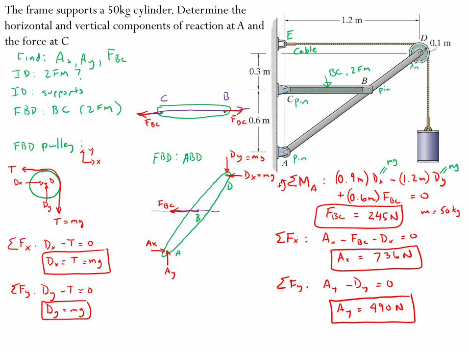
The frame supports a 50kg cylinder. Determine the
horizontal and vertical components of reaction at A and
the force at C
Chapter 7: Internal Forces
Goals and Objectives
• Determine the internal loadings in members using the method
of sections
• Generalize this procedure and formulate equations that
describe the internal shear force and bending moment
throughout a member
• Be able to construct or identify shear a force nd bending
moment diagrams for beams when distributed loads,
concentrated forces, and/or concentrated couple moments are
applied
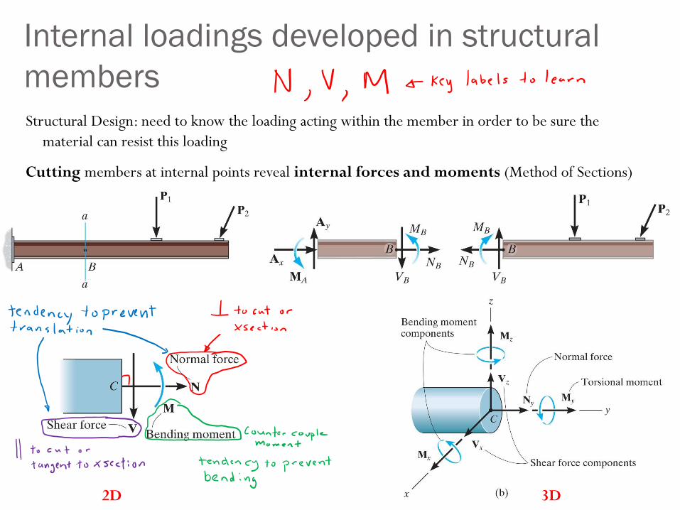
Internal loadings developed in structural
members
Structural Design: need to know the loading acting within the member in order to be sure the
material can resist this loading
Cutting members at internal points reveal internal forces and moments (Method of Sections)
2D 3D

Sign conventions:
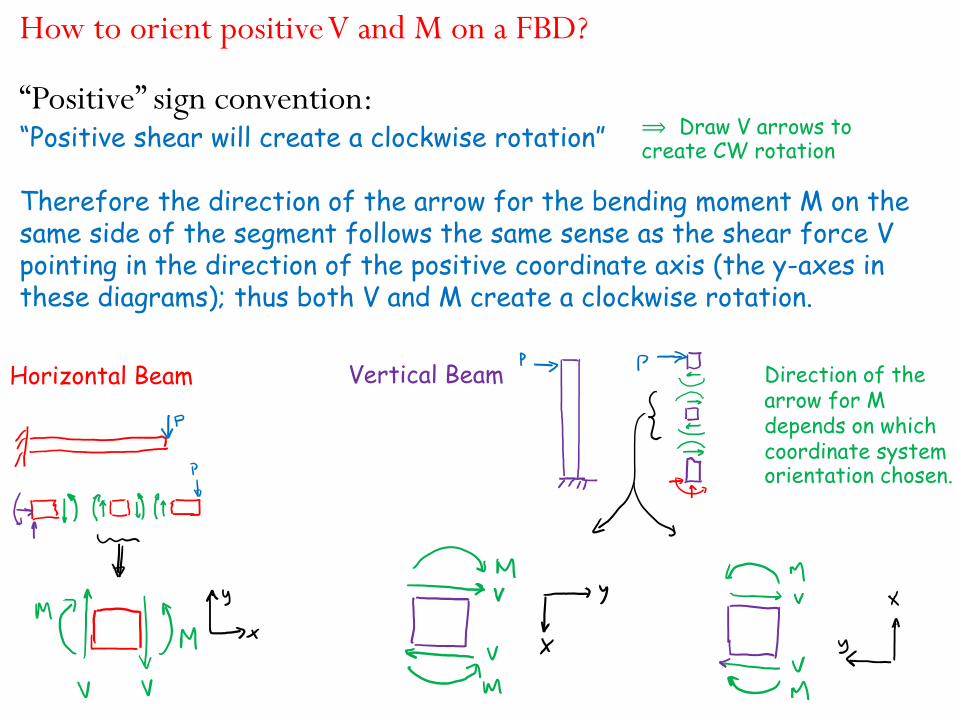
How to orient positive V and M on a FBD?
“Positive” sign convention:“Positive shear will create a clockwise rotation”
Therefore the direction of the arrow for the bending moment M on the same side of the segment follows the same sense as the shear force V pointing in the direction of the positive coordinate axis (the y-axes in these diagrams); thus both V and M create a clockwise rotation.
Direction of the arrow for M depends on which coordinate system orientation chosen.
Horizontal Beam Vertical Beam
⟹ Draw V arrows to create CW rotation
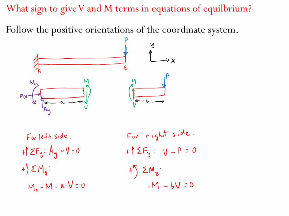
What sign to give V and M terms in equations of equilbrium?
Follow the positive orientations of the coordinate system.
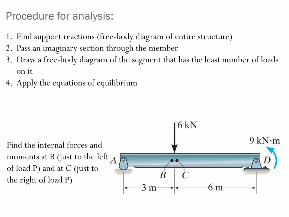
Procedure for analysis:
1. Find support reactions (free-body diagram of entire structure)
2. Pass an imaginary section through the member
3. Draw a free-body diagram of the segment that has the least number of loads
on it
4. Apply the equations of equilibrium
Find the internal forces and
moments at B (just to the left
of load P) and at C (just to
the right of load P)
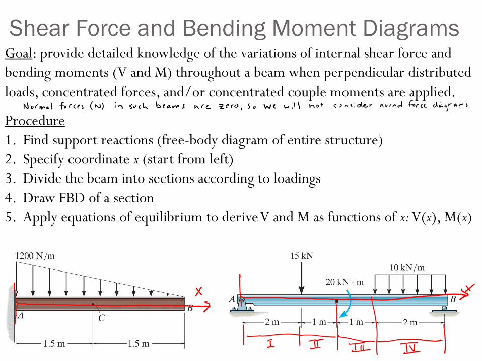
Shear Force and Bending Moment DiagramsGoal: provide detailed knowledge of the variations of internal shear force and
bending moments (V and M) throughout a beam when perpendicular distributed
loads, concentrated forces, and/or concentrated couple moments are applied.
Procedure
1. Find support reactions (free-body diagram of entire structure)
2. Specify coordinate x (start from left)
3. Divide the beam into sections according to loadings
4. Draw FBD of a section
5. Apply equations of equilibrium to derive V and M as functions of x: V(x), M(x)
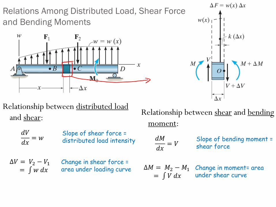
Relationship between distributed load
and shear:Relationship between shear and bending
moment:
Relations Among Distributed Load, Shear Force
and Bending Moments
Slope of shear force = distributed load intensity
Change in shear force = area under loading curve
𝑑𝑉
𝑑𝑥= 𝑤
Δ𝑉 = 𝑉2 − 𝑉1= 𝑤 𝑑𝑥
Slope of bending moment = shear force
Change in moment= area under shear curve
𝑑𝑀
𝑑𝑥= 𝑉
Δ𝑀 = 𝑀2 −𝑀1
= 𝑉 𝑑𝑥
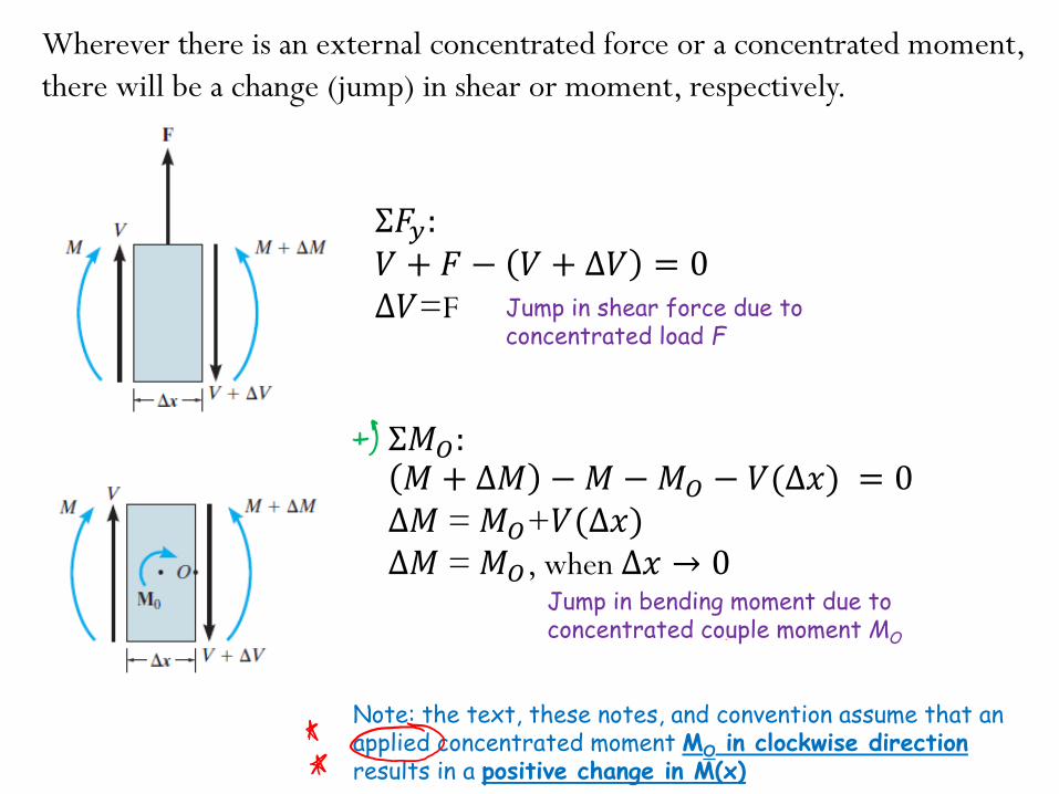
Wherever there is an external concentrated force or a concentrated moment,
there will be a change (jump) in shear or moment, respectively.
Σ𝐹𝑦:𝑉 + 𝐹 − 𝑉 + Δ𝑉 = 0Δ𝑉=F
Σ𝑀𝑂:𝑀 + Δ𝑀 −𝑀 −𝑀𝑂 − 𝑉(Δ𝑥) = 0Δ𝑀 = 𝑀𝑂+𝑉(Δ𝑥)Δ𝑀 = 𝑀𝑂, when ∆𝑥 → 0
Note: the text, these notes, and convention assume that an applied concentrated moment MO in clockwise direction results in a positive change in M(x)
Jump in shear force due to concentrated load F
Jump in bending moment due to concentrated couple moment MO
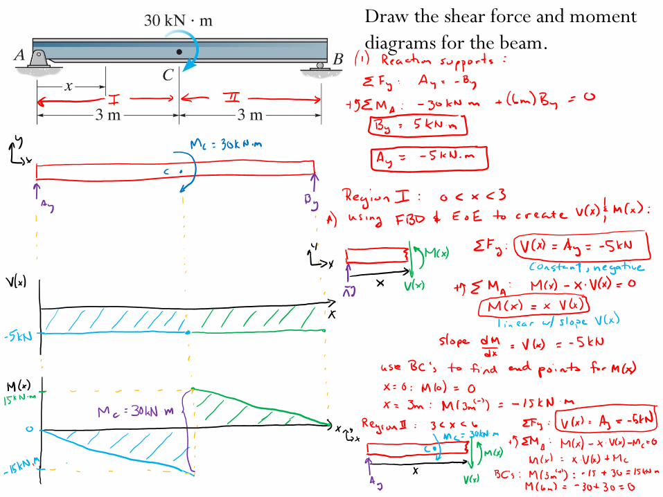
Draw the shear force and moment
diagrams for the beam.
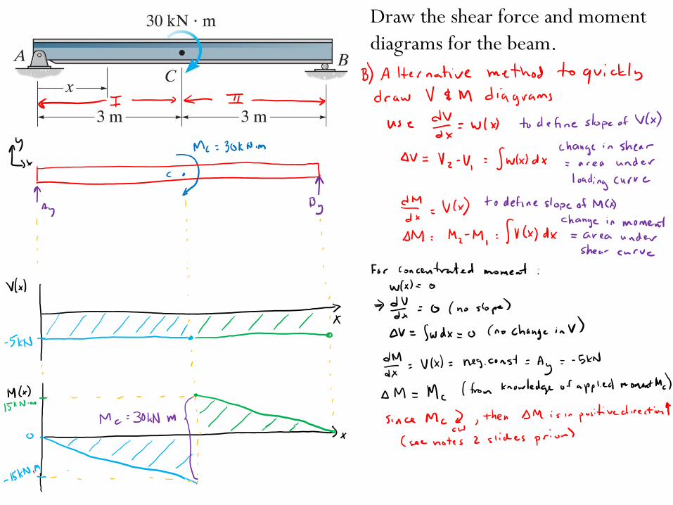
Draw the shear force and moment
diagrams for the beam.
Chapter 8: Friction
Goals and Objectives
• Sections 8.1-8.2
• Introduce the concept of dry friction
• Analyze the equilibrium of rigid bodies subjected to this force
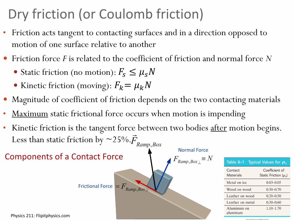
Dry friction (or Coulomb friction) • Friction acts tangent to contacting surfaces and in a direction opposed to
motion of one surface relative to another
Friction force F is related to the coefficient of friction and normal force N
Static friction (no motion): 𝐹𝑠 ≤ 𝜇𝑠𝑁
Kinetic friction (moving): 𝐹𝑘= 𝜇𝑘𝑁
Magnitude of coefficient of friction depends on the two contacting materials
• Maximum static frictional force occurs when motion is impending
• Kinetic friction is the tangent force between two bodies after motion begins.
Less than static friction by ~25%.
Physics 211: Flipitphysics.com
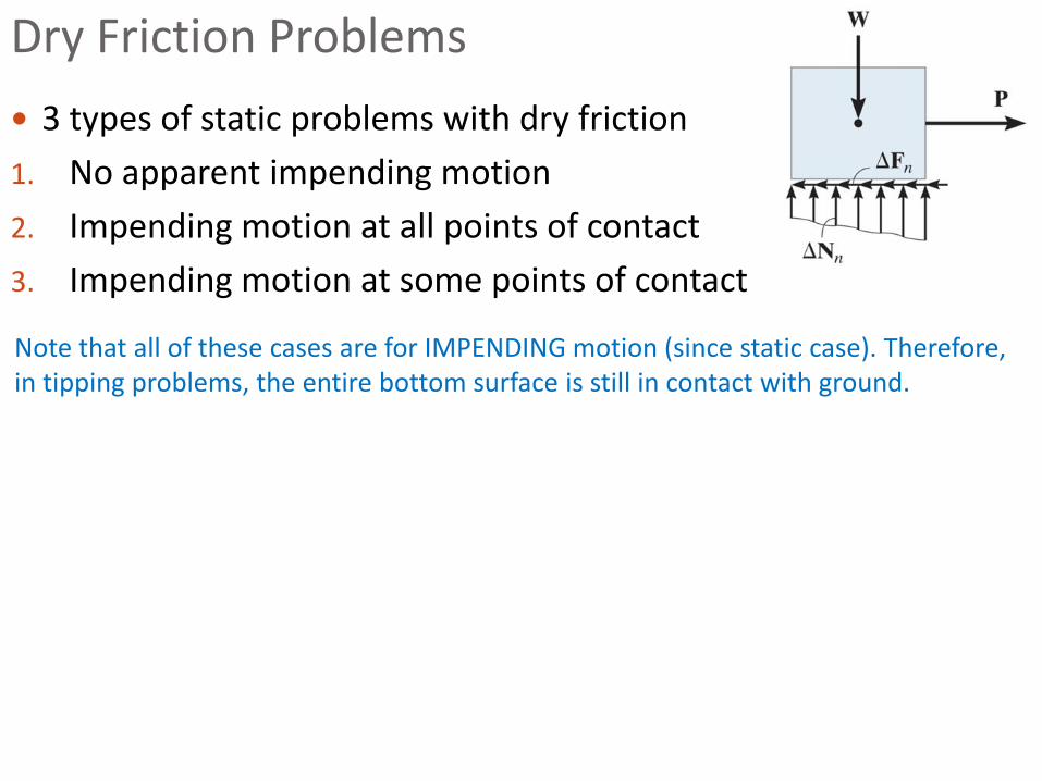
3 types of static problems with dry friction
1. No apparent impending motion
2. Impending motion at all points of contact
3. Impending motion at some points of contact
Dry Friction Problems
Note that all of these cases are for IMPENDING motion (since static case). Therefore, in tipping problems, the entire bottom surface is still in contact with ground.
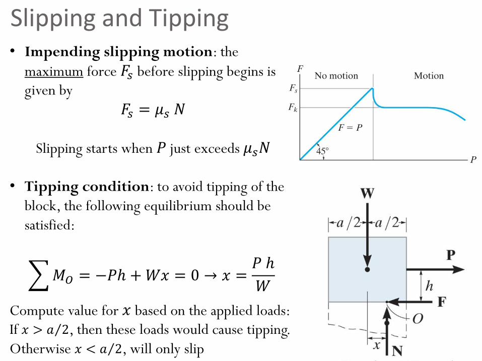
Slipping and Tipping• Impending slipping motion: the
maximum force 𝐹𝑠 before slipping begins is
given by
𝐹𝑠 = 𝜇𝑠 𝑁
Slipping starts when 𝑃 just exceeds 𝜇𝑠𝑁
• Tipping condition: to avoid tipping of the
block, the following equilibrium should be
satisfied:
𝑀𝑂 = −𝑃ℎ +𝑊𝑥 = 0 → 𝑥 =𝑃 ℎ
𝑊
Compute value for 𝑥 based on the applied loads:
If 𝑥 > Τ𝑎 2, then these loads would cause tipping.
Otherwise 𝑥 < Τ𝑎 2, will only slip
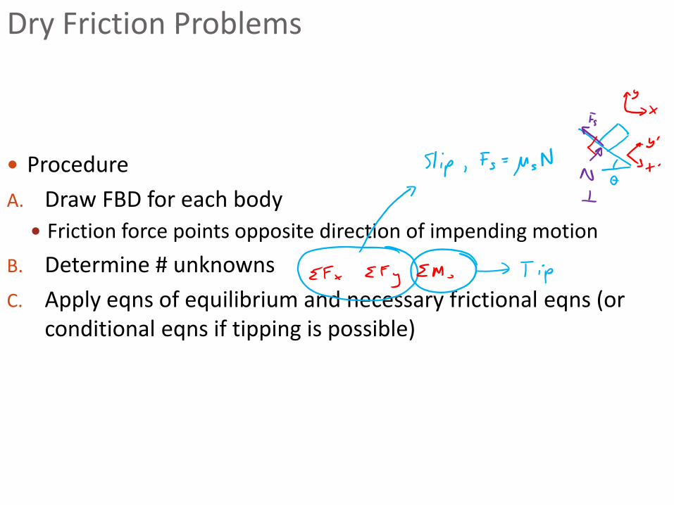
Procedure
A. Draw FBD for each body
Friction force points opposite direction of impending motion
B. Determine # unknowns
C. Apply eqns of equilibrium and necessary frictional eqns (or conditional eqns if tipping is possible)
Dry Friction Problems
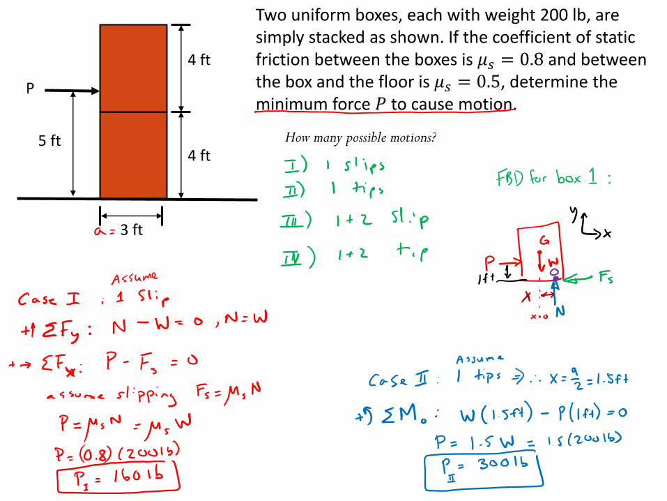
Two uniform boxes, each with weight 200 lb, are simply stacked as shown. If the coefficient of static friction between the boxes is 𝜇𝑠 = 0.8 and between the box and the floor is 𝜇𝑠 = 0.5, determine the minimum force 𝑃 to cause motion.
4 ft
4 ft
3 ft
P
5 ft How many possible motions?


![Cartridge Valves Technical Information Solenoid Valves …...CP502-3 SDC16-2 130 l/min [34 US gal/min] 210 bar [3000 psi] 10.25 CP503-3 SDC20-2 230 l/min [61 US gal/min] 210 bar [3000](https://img.pdfslide.net/doc/110x75/60af484c7b93c40be563b47b/cartridge-valves-technical-information-solenoid-valves-cp502-3-sdc16-2-130-lmin.jpg)