Embed Size (px)
Citation preview

Statics, Fourteenth EditionR.C. Hibbeler
Copyright ©2016 by Pearson Education, Inc.All rights reserved.
STATICS
FE Review
Statics, Fourteenth EditionR.C. Hibbeler
Copyright ©2016 by Pearson Education, Inc.All rights reserved.
1. Resultants of force systems
Statics, Fourteenth EditionR.C. Hibbeler
Copyright ©2016 by Pearson Education, Inc.All rights reserved.
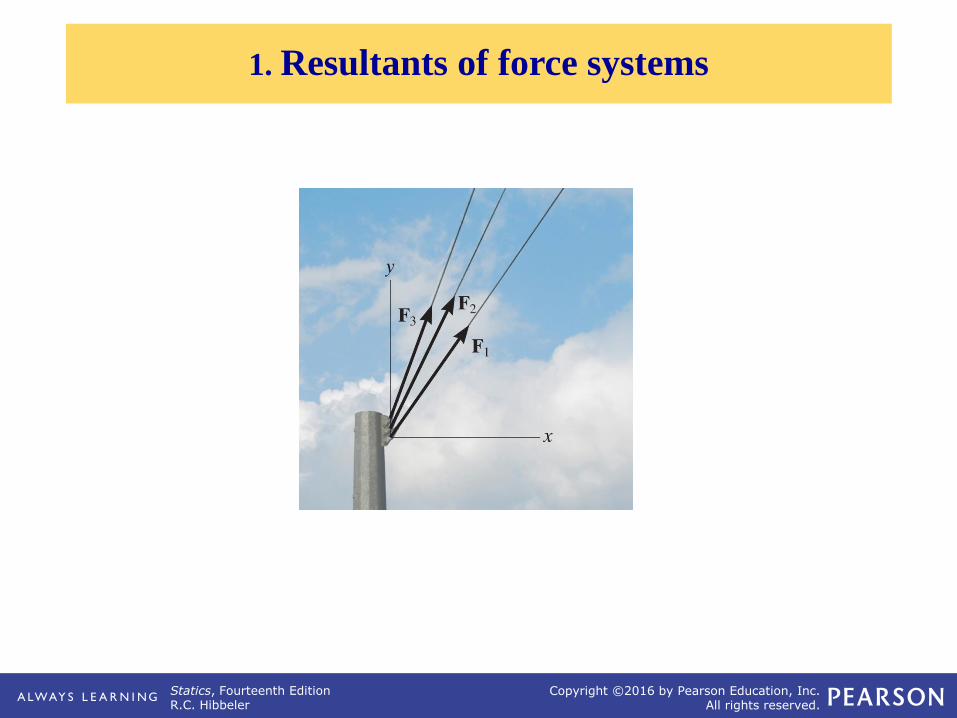
VECTOR OPERATIONS (Section 2.2)
Scalar Multiplication
and Division

Statics, Fourteenth EditionR.C. Hibbeler
Copyright ©2016 by Pearson Education, Inc.All rights reserved.
VECTOR ADDITION USING EITHER THEPARALLELOGRAM LAW OR TRIANGLE
Parallelogram Law:
Triangle method
(always ‘tip to tail’):
How do you subtract a vector?
How can you add more than two concurrent vectors graphically?

Statics, Fourteenth EditionR.C. Hibbeler
Copyright ©2016 by Pearson Education, Inc.All rights reserved.
“Resolution” of a vector is breaking up a vector into components.
It is kind of like using the parallelogram law in reverse.
RESOLUTION OF A VECTOR

Statics, Fourteenth EditionR.C. Hibbeler
Copyright ©2016 by Pearson Education, Inc.All rights reserved.
ADDITION OF A SYSTEM OF COPLANAR FORCES (Section 2.4)
• Each component of the vector is
shown as a magnitude and a
direction.
• The directions are based on the x and y axes. We use the
“unit vectors” i and j to designate the x and y-axes.
• We ‘resolve’ vectors into
components using the x and y-axis
coordinate system.
Statics, Fourteenth EditionR.C. Hibbeler
Copyright ©2016 by Pearson Education, Inc.All rights reserved.
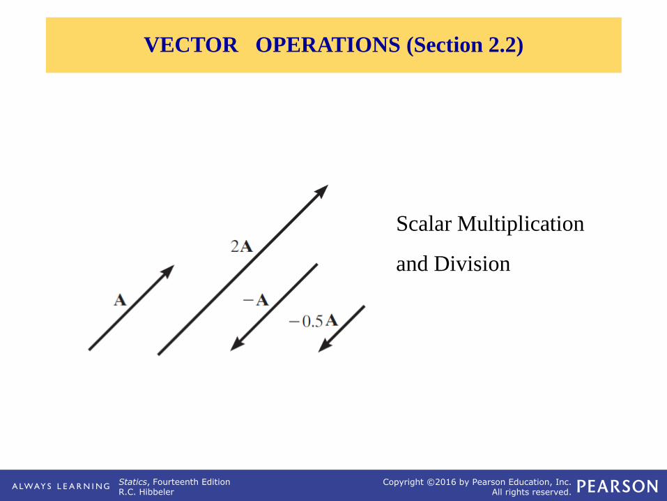
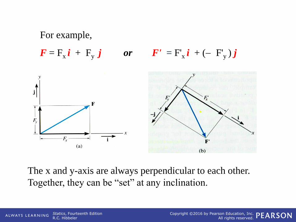
For example,
F = Fx i + Fy j or F' = F'x i + (− F'y ) j
The x and y-axis are always perpendicular to each other.
Together, they can be “set” at any inclination.

Statics, Fourteenth EditionR.C. Hibbeler
Copyright ©2016 by Pearson Education, Inc.All rights reserved.
• Step 2 is to add all the x-
components together, followed by
adding all the y-components
together. These two totals are the
x and y-components of the
resultant vector.
• Step 1 is to resolve each force
into its components.
ADDITION OF SEVERAL VECTORS
• Step 3 is to find the magnitude
and angle of the resultant
vector.

Statics, Fourteenth EditionR.C. Hibbeler
Copyright ©2016 by Pearson Education, Inc.All rights reserved.
Break the three vectors into components, then add them.
FR = F1 + F2 + F3
= F1x i + F1y j − F2x i + F2y j + F3x i − F3y j
= (F1x − F2x + F3x) i + (F1y + F2y − F3y) j
= (FRx) i + (FRy) j
An example of the process:
Statics, Fourteenth EditionR.C. Hibbeler
Copyright ©2016 by Pearson Education, Inc.All rights reserved.
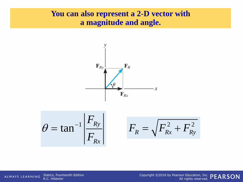
You can also represent a 2-D vector with a magnitude and angle.
1tanRy
Rx
F
F −=
2 2
R Rx RyF F F= +

Statics, Fourteenth EditionR.C. Hibbeler
Copyright ©2016 by Pearson Education, Inc.All rights reserved.
Plan:
a) Resolve the forces into their x-y components.
b) Add the respective components to get the resultant vector.
c) Find magnitude and angle from the resultant components.
EXAMPLE I
Given: Three concurrent forces
acting on a tent post.
Find: The magnitude and
angle of the resultant
force.

Statics, Fourteenth EditionR.C. Hibbeler
Copyright ©2016 by Pearson Education, Inc.All rights reserved.
EQUILIBRIUM OF A PARTICLE, THE FREE-BODY DIAGRAM

Statics, Fourteenth EditionR.C. Hibbeler
Copyright ©2016 by Pearson Education, Inc.All rights reserved.
For a spool of given
weight, how would you
find the forces in cables
AB and AC? If designing
a spreader bar like the one
being used here, you need
to know the forces to make
sure the rigging doesn’t
fail.
APPLICATIONS
Statics, Fourteenth EditionR.C. Hibbeler
Copyright ©2016 by Pearson Education, Inc.All rights reserved.
APPLICATIONS (continued)

Statics, Fourteenth EditionR.C. Hibbeler
Copyright ©2016 by Pearson Education, Inc.All rights reserved.
SIMPLE SPRINGS

Statics, Fourteenth EditionR.C. Hibbeler
Copyright ©2016 by Pearson Education, Inc.All rights reserved.
CABLES AND PULLEYS
T1
T2

Statics, Fourteenth EditionR.C. Hibbeler
Copyright ©2016 by Pearson Education, Inc.All rights reserved.
Given: The mass of lamp is 20 kg
and geometry is as shown.
Find: The force in each cable.
Plan:
GROUP PROBLEM SOLVING

Statics, Fourteenth EditionR.C. Hibbeler
Copyright ©2016 by Pearson Education, Inc.All rights reserved.
EQUIVALENT FORCE SYSTEMS
Statics, Fourteenth EditionR.C. Hibbeler
Copyright ©2016 by Pearson Education, Inc.All rights reserved.
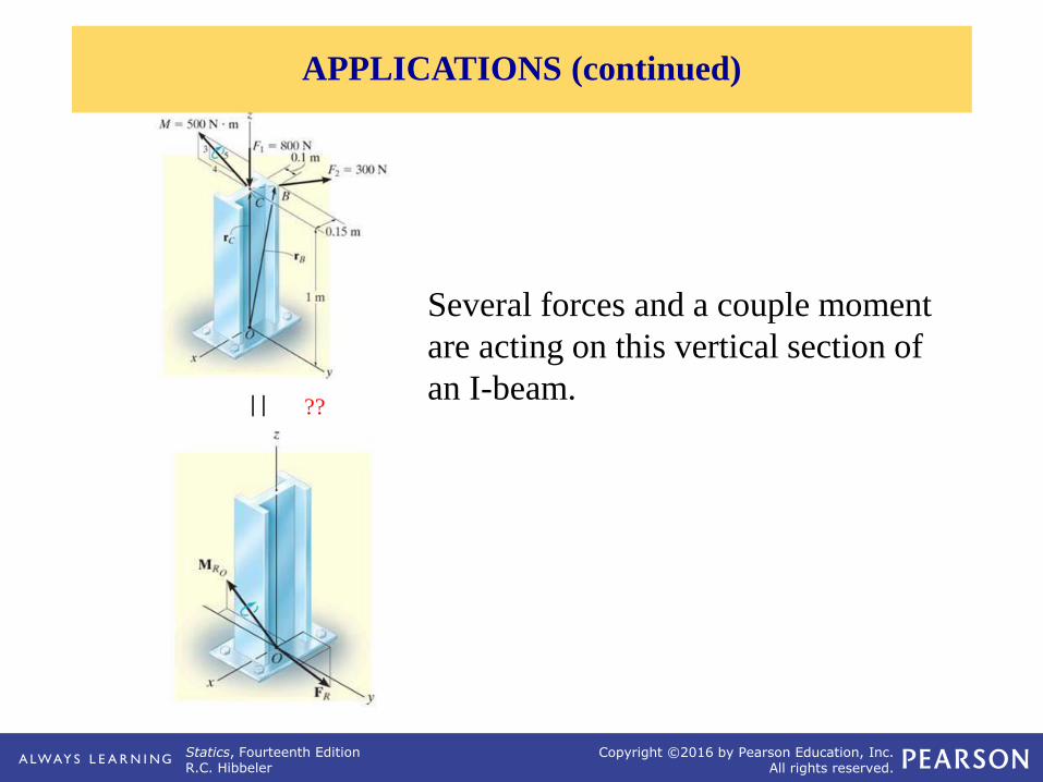
Several forces and a couple moment
are acting on this vertical section of
an I-beam.| | ??
APPLICATIONS (continued)

Statics, Fourteenth EditionR.C. Hibbeler
Copyright ©2016 by Pearson Education, Inc.All rights reserved.
SIMPLIFICATION OF FORCE AND COUPLE SYSTEM (Section 4.7)
Statics, Fourteenth EditionR.C. Hibbeler
Copyright ©2016 by Pearson Education, Inc.All rights reserved.
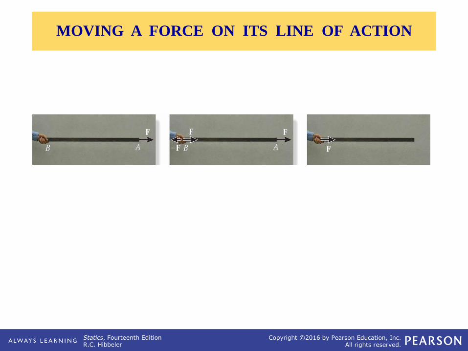
MOVING A FORCE ON ITS LINE OF ACTION

Statics, Fourteenth EditionR.C. Hibbeler
Copyright ©2016 by Pearson Education, Inc.All rights reserved.
B
MOVING A FORCE OFF OF ITS LINE OF ACTION

Statics, Fourteenth EditionR.C. Hibbeler
Copyright ©2016 by Pearson Education, Inc.All rights reserved.
SIMPLIFICATION OF A FORCE AND COUPLE SYSTEM

Statics, Fourteenth EditionR.C. Hibbeler
Copyright ©2016 by Pearson Education, Inc.All rights reserved.
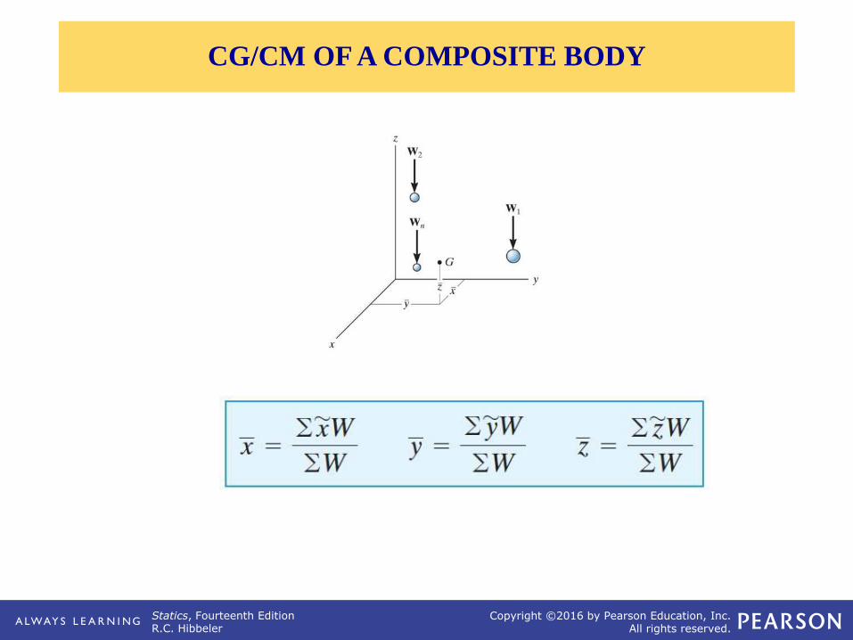
WR = W1 + W2
(MR)o = W1 d1 + W2 d2
SIMPLIFICATION OF A FORCE AND COUPLE SYSTEM (continued)

Statics, Fourteenth EditionR.C. Hibbeler
Copyright ©2016 by Pearson Education, Inc.All rights reserved.
Given: A 2-D force and couple
system as shown.
Find: The equivalent resultant
force and couple
moment acting at A.
Plan:
GROUP PROBLEM SOLVING I
Statics, Fourteenth EditionR.C. Hibbeler
Copyright ©2016 by Pearson Education, Inc.All rights reserved.
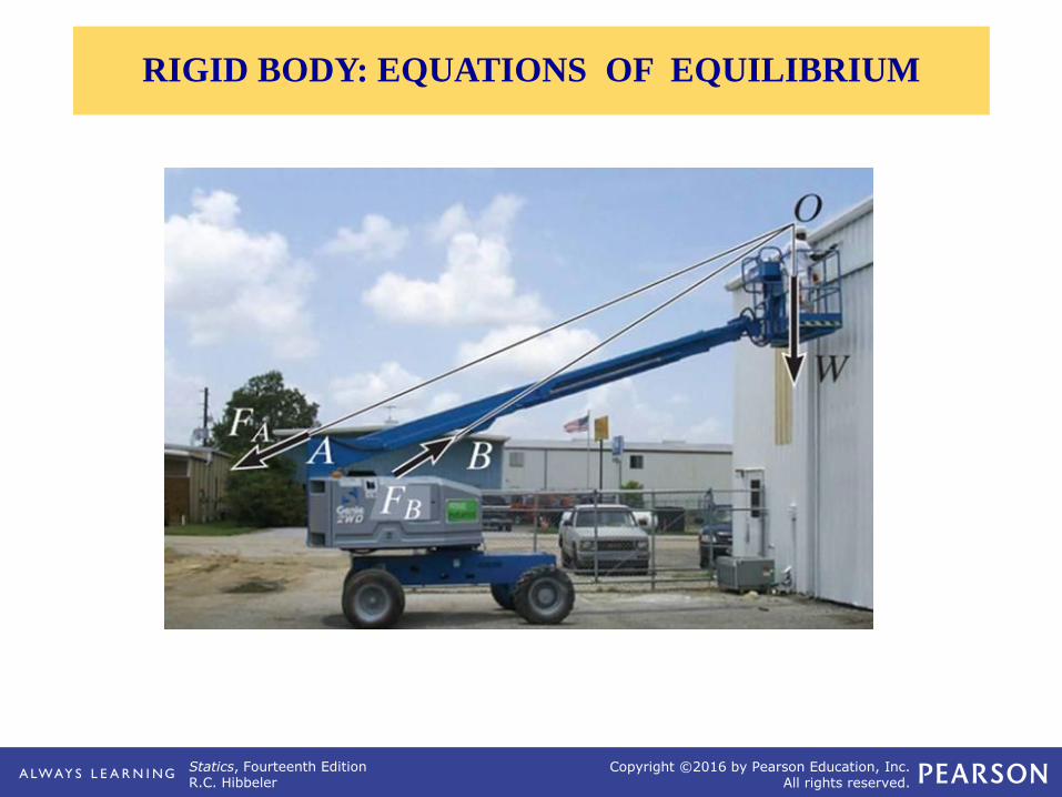
RIGID BODY: EQUATIONS OF EQUILIBRIUM
Statics, Fourteenth EditionR.C. Hibbeler
Copyright ©2016 by Pearson Education, Inc.All rights reserved.
A
APPLICATIONS

Statics, Fourteenth EditionR.C. Hibbeler
Copyright ©2016 by Pearson Education, Inc.All rights reserved.
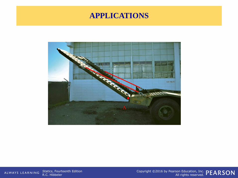
APPLICATIONS (continued)
Statics, Fourteenth EditionR.C. Hibbeler
Copyright ©2016 by Pearson Education, Inc.All rights reserved.
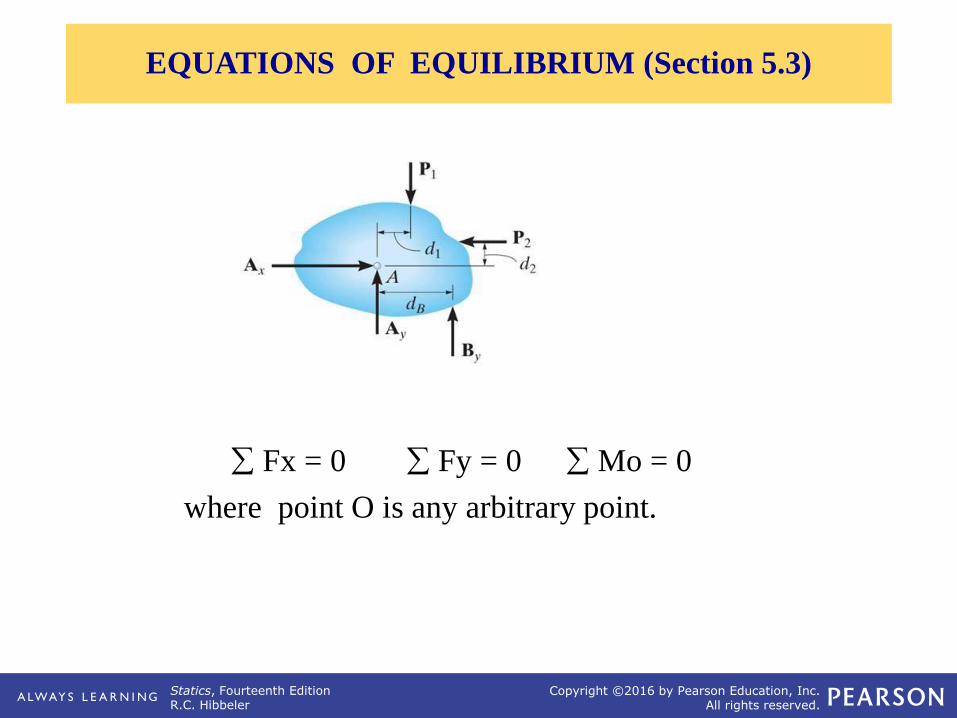
Fx = 0 Fy = 0 Mo = 0
where point O is any arbitrary point.
EQUATIONS OF EQUILIBRIUM (Section 5.3)
Statics, Fourteenth EditionR.C. Hibbeler
Copyright ©2016 by Pearson Education, Inc.All rights reserved.
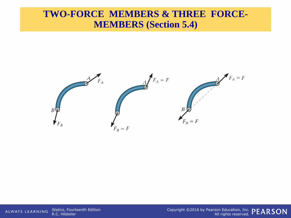
TWO-FORCE MEMBERS & THREE FORCE-MEMBERS (Section 5.4)

Statics, Fourteenth EditionR.C. Hibbeler
Copyright ©2016 by Pearson Education, Inc.All rights reserved.
EXAMPLES OF TWO-FORCE MEMBERS

Statics, Fourteenth EditionR.C. Hibbeler
Copyright ©2016 by Pearson Education, Inc.All rights reserved.
Given: The 4kN load at B of
the beam is supported
by pins at A and C.
Find: The support reactions
at A and C.
Plan:
EXAMPLE

Statics, Fourteenth EditionR.C. Hibbeler
Copyright ©2016 by Pearson Education, Inc.All rights reserved.
SIMPLE TRUSSES, THE METHOD OF JOINTS, & ZERO-FORCE MEMBERS

Statics, Fourteenth EditionR.C. Hibbeler
Copyright ©2016 by Pearson Education, Inc.All rights reserved.
A free-body diagram of Joint B
THE METHOD OF JOINTS (Section 6.2)
Statics, Fourteenth EditionR.C. Hibbeler
Copyright ©2016 by Pearson Education, Inc.All rights reserved.
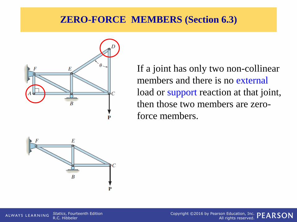
ZERO-FORCE MEMBERS (Section 6.3)
If a joint has only two non-collinear
members and there is no external
load or support reaction at that joint,
then those two members are zero-
force members.
Statics, Fourteenth EditionR.C. Hibbeler
Copyright ©2016 by Pearson Education, Inc.All rights reserved.
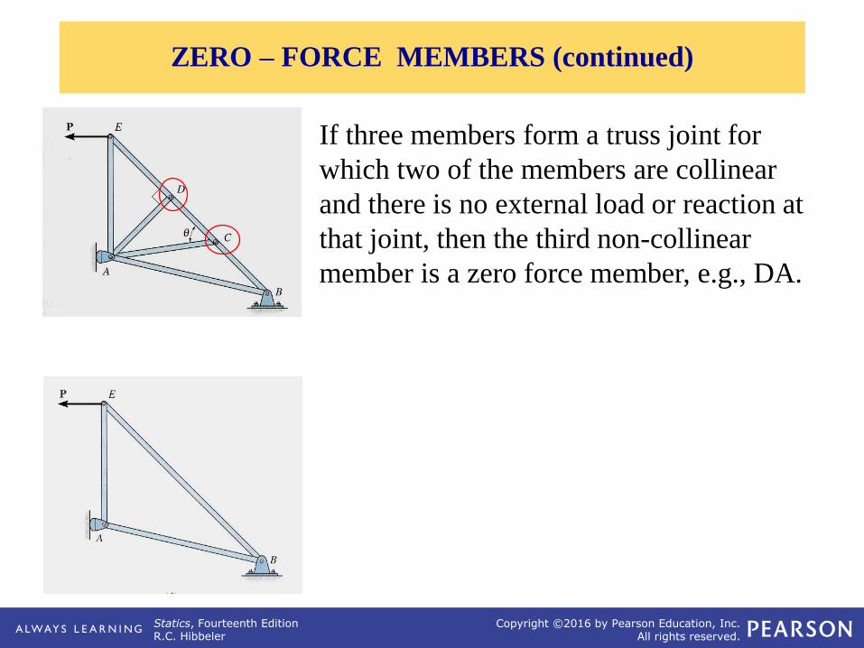
If three members form a truss joint for
which two of the members are collinear
and there is no external load or reaction at
that joint, then the third non-collinear
member is a zero force member, e.g., DA.
ZERO – FORCE MEMBERS (continued)

Statics, Fourteenth EditionR.C. Hibbeler
Copyright ©2016 by Pearson Education, Inc.All rights reserved.
Given: Loads as shown on the truss
Find: The forces in each member
of the truss.
Plan:
EXAMPLE

Statics, Fourteenth EditionR.C. Hibbeler
Copyright ©2016 by Pearson Education, Inc.All rights reserved.
THE METHOD OF SECTIONS

Statics, Fourteenth EditionR.C. Hibbeler
Copyright ©2016 by Pearson Education, Inc.All rights reserved.
APPLICATIONS
Statics, Fourteenth EditionR.C. Hibbeler
Copyright ©2016 by Pearson Education, Inc.All rights reserved.
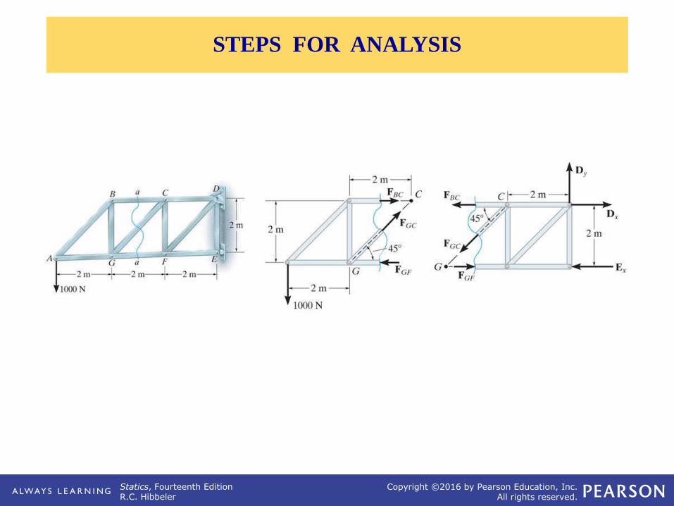
STEPS FOR ANALYSIS

Statics, Fourteenth EditionR.C. Hibbeler
Copyright ©2016 by Pearson Education, Inc.All rights reserved.
Given: Loads as shown on the
truss.
Find: The force in members
KJ, KD, and CD.
Plan:
EXAMPLE
Statics, Fourteenth EditionR.C. Hibbeler
Copyright ©2016 by Pearson Education, Inc.All rights reserved.
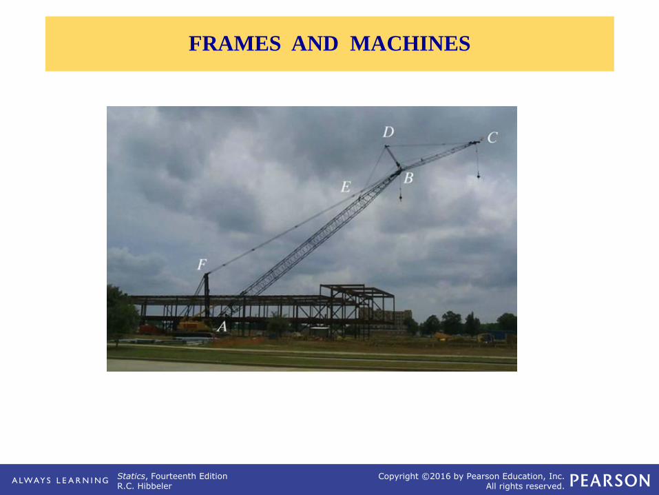
FRAMES AND MACHINES

Statics, Fourteenth EditionR.C. Hibbeler
Copyright ©2016 by Pearson Education, Inc.All rights reserved.
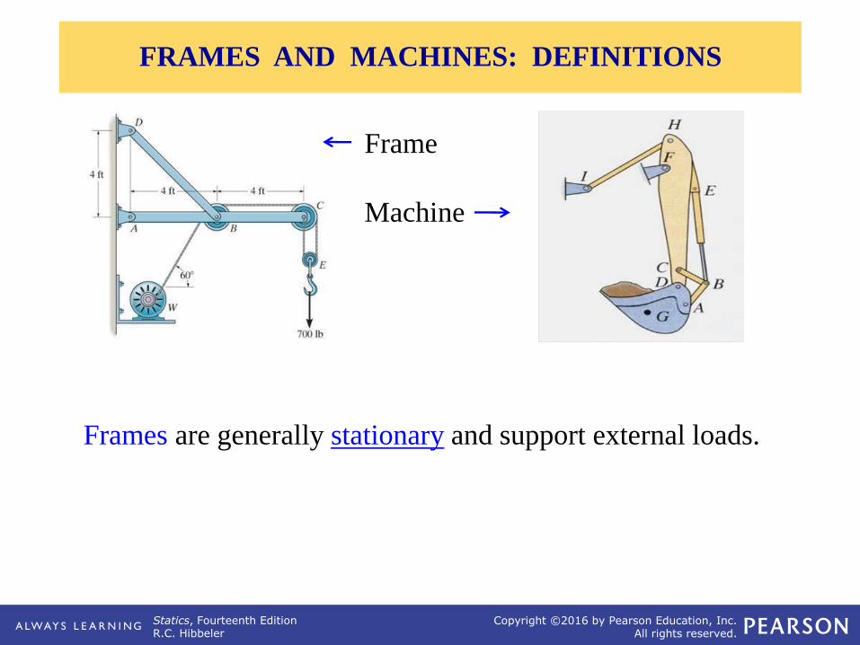
“Machines,” like those above, are used in a variety of
applications. How are they different from trusses and frames?
APPLICATIONS
Statics, Fourteenth EditionR.C. Hibbeler
Copyright ©2016 by Pearson Education, Inc.All rights reserved.
Frames are generally stationary and support external loads.
Frame
Machine
FRAMES AND MACHINES: DEFINITIONS

Statics, Fourteenth EditionR.C. Hibbeler
Copyright ©2016 by Pearson Education, Inc.All rights reserved.
FAB
STEPS FOR ANALYZING A FRAME OR MACHINE
Statics, Fourteenth EditionR.C. Hibbeler
Copyright ©2016 by Pearson Education, Inc.All rights reserved.
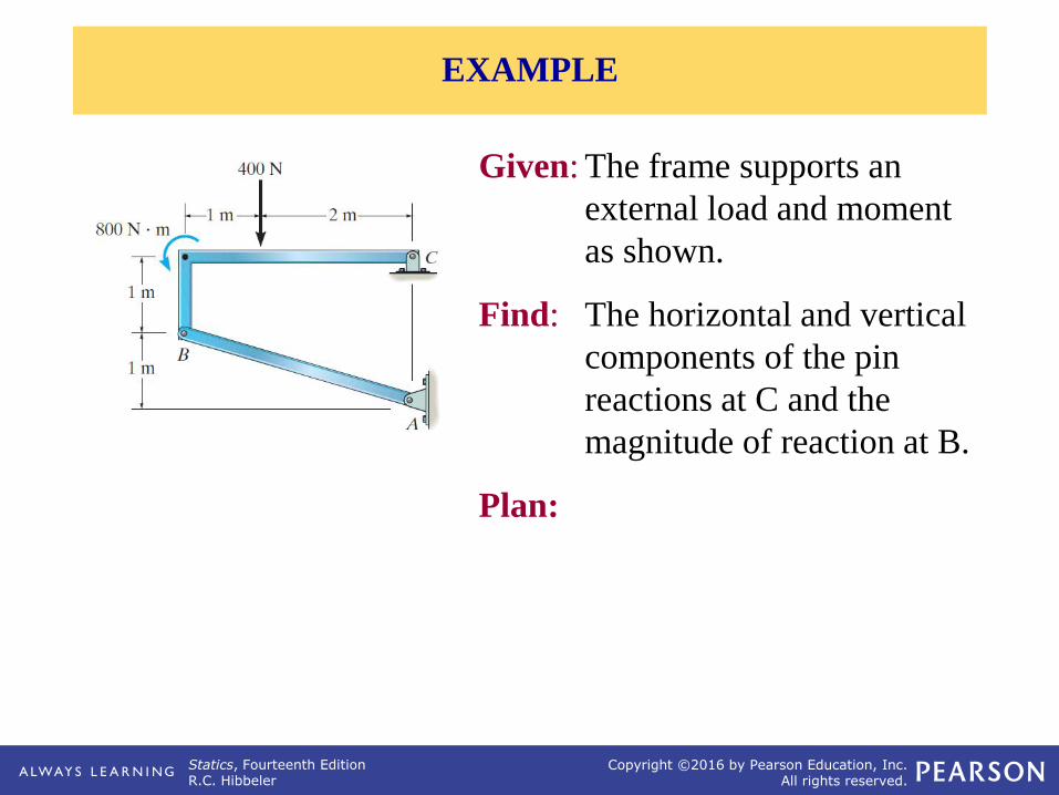
EXAMPLE
Given: The frame supports an
external load and moment
as shown.
Find: The horizontal and vertical
components of the pin
reactions at C and the
magnitude of reaction at B.
Plan:

Statics, Fourteenth EditionR.C. Hibbeler
Copyright ©2016 by Pearson Education, Inc.All rights reserved.
CHARACTERISTICS OF DRY FRICTION

Statics, Fourteenth EditionR.C. Hibbeler
Copyright ©2016 by Pearson Education, Inc.All rights reserved.
In designing a brake system for a
bicycle, car, or any other vehicle, it is
important to understand the frictional
forces involved.
APPLICATIONS

Statics, Fourteenth EditionR.C. Hibbeler
Copyright ©2016 by Pearson Education, Inc.All rights reserved.
The rope is used to tow the
refrigerator.
In order to move the refrigerator, is
it best to pull up as shown, pull
horizontally, or pull downwards on
the rope?
APPLICATIONS (continued)

Statics, Fourteenth EditionR.C. Hibbeler
Copyright ©2016 by Pearson Education, Inc.All rights reserved.
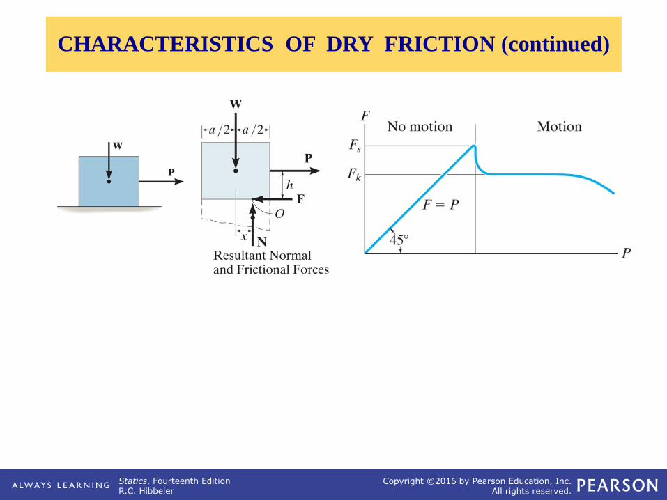
Friction is defined as a force of resistance
acting on a body which prevents or resists the
slipping of a body relative to a second body.
Experiments show that frictional forces act
tangent (parallel) to the contacting surface in
a direction opposing the relative motion or
tendency for motion.
For the body shown in the figure to be in
equilibrium, the following must be true:
F = P, N = W, and W*x = P*h.
CHARACTERISTICS OF DRY FRICTION (Section 8.1)
Statics, Fourteenth EditionR.C. Hibbeler
Copyright ©2016 by Pearson Education, Inc.All rights reserved.
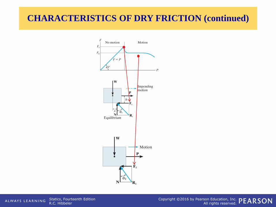
CHARACTERISTICS OF DRY FRICTION (continued)
Statics, Fourteenth EditionR.C. Hibbeler
Copyright ©2016 by Pearson Education, Inc.All rights reserved.
CHARACTERISTICS OF DRY FRICTION (continued)

Statics, Fourteenth EditionR.C. Hibbeler
Copyright ©2016 by Pearson Education, Inc.All rights reserved.
For a given W and h of the box,
how can we determine if the block
will slide or tip first? In this case,
we have four unknowns (F, N, x,
and P) and only the three E-of-E.
IMPENDING TIPPING versus SLIPPING

Statics, Fourteenth EditionR.C. Hibbeler
Copyright ©2016 by Pearson Education, Inc.All rights reserved.
Assume: Slipping occurs
Known: F = s N
Solve: x, P, and N
Check: 0 x b/2
Or
Assume: Tipping occurs
Known: x = b/2
Solve: P, N, and F
Check: F s N
IMPENDING TIPPING versus SLIPPING (continued)
Statics, Fourteenth EditionR.C. Hibbeler
Copyright ©2016 by Pearson Education, Inc.All rights reserved.
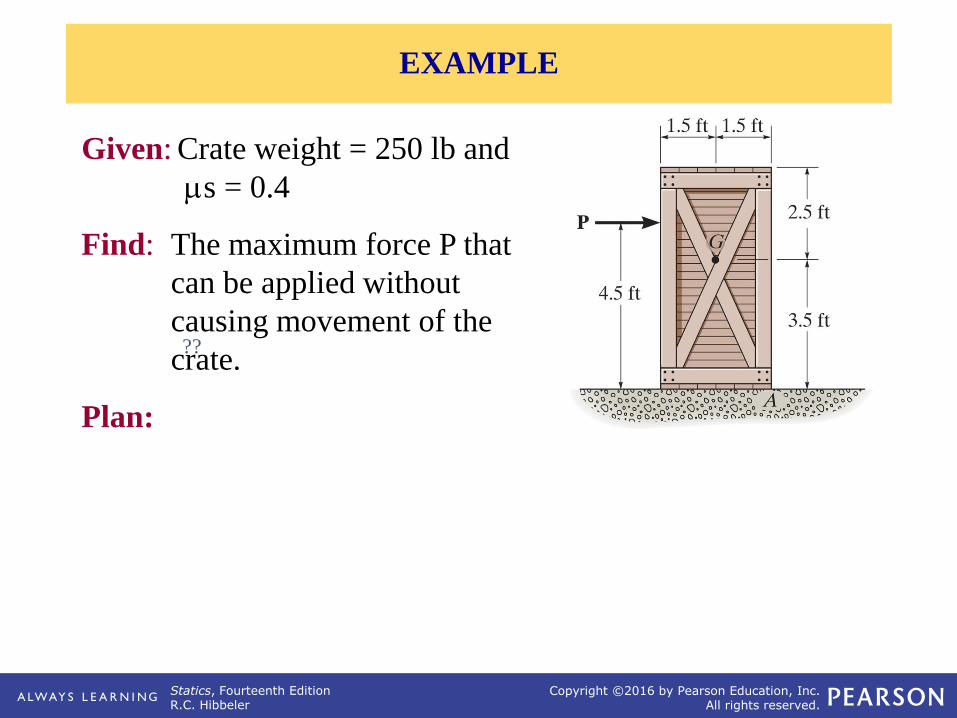
Given: Crate weight = 250 lb and
s = 0.4
Find: The maximum force P that
can be applied without
causing movement of the
crate.
Plan:
??
EXAMPLE
Statics, Fourteenth EditionR.C. Hibbeler
Copyright ©2016 by Pearson Education, Inc.All rights reserved.
x
1.5 ft 1.5 ft
250 lb
0
F
FBD of the crate
P
N
3.5 ft
4.5 ft
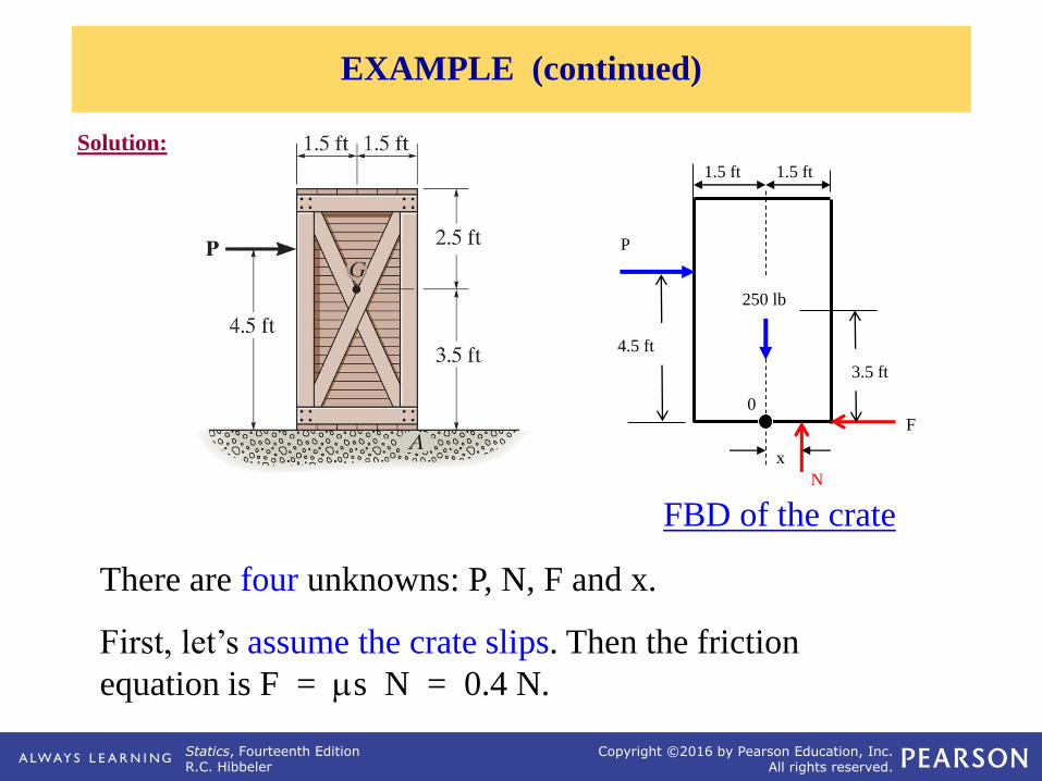
There are four unknowns: P, N, F and x.
First, let’s assume the crate slips. Then the friction
equation is F = s N = 0.4 N.
Solution:
EXAMPLE (continued)
Statics, Fourteenth EditionR.C. Hibbeler
Copyright ©2016 by Pearson Education, Inc.All rights reserved.
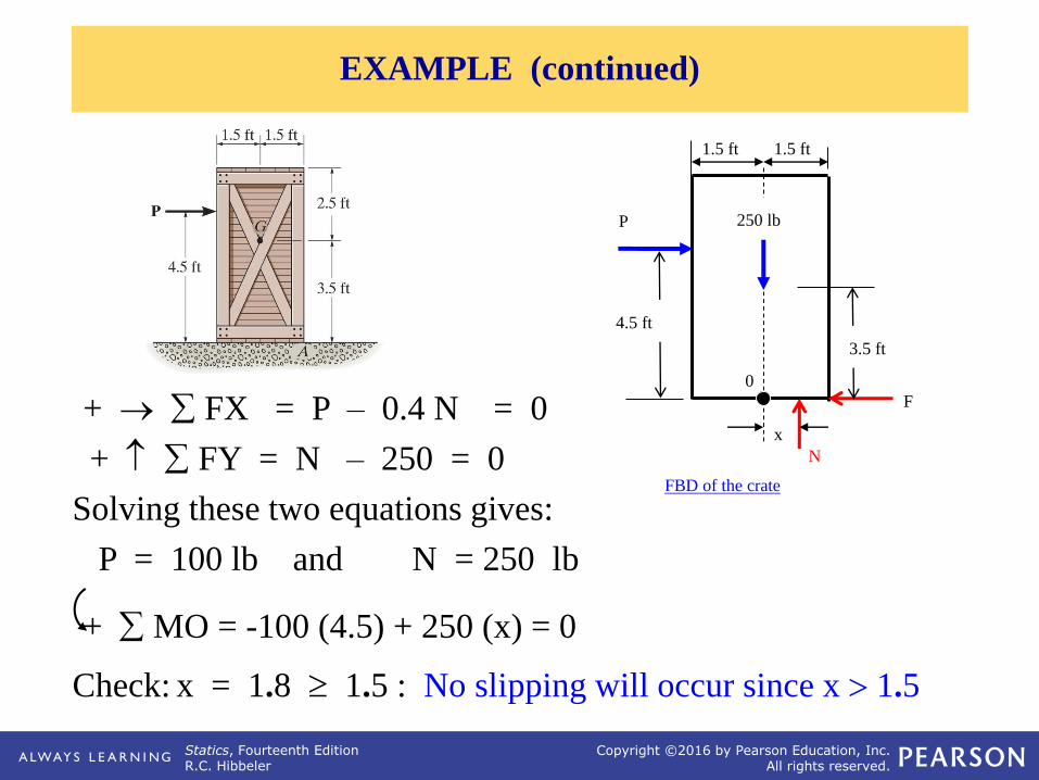
+ → FX = P – 0.4 N = 0
+ FY = N – 250 = 0
Solving these two equations gives:
P = 100 lb and N = 250 lb
+ MO = -100 (4.5) + 250 (x) = 0
Check: x = 1.8 1.5 : No slipping will occur since x 1.5
EXAMPLE (continued)
x
1.5 ft 1.5 ft
250 lb
0
F
FBD of the crate
P
N
3.5 ft
4.5 ft
Statics, Fourteenth EditionR.C. Hibbeler
Copyright ©2016 by Pearson Education, Inc.All rights reserved.
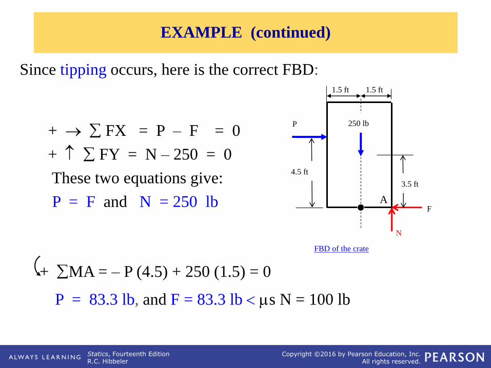
+ → FX = P – F = 0
+ FY = N – 250 = 0
These two equations give:
P = F and N = 250 lb
+ MA = – P (4.5) + 250 (1.5) = 0
P = 83.3 lb, and F = 83.3 lb s N = 100 lb
Since tipping occurs, here is the correct FBD:
EXAMPLE (continued)
1.5 ft 1.5 ft
250 lb
AF
FBD of the crate
P
N
3.5 ft
4.5 ft
Statics, Fourteenth EditionR.C. Hibbeler
Copyright ©2016 by Pearson Education, Inc.All rights reserved.
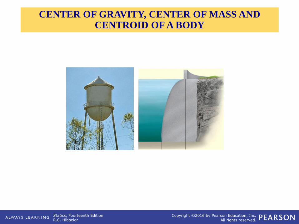
CENTER OF GRAVITY, CENTER OF MASS AND CENTROID OF A BODY

Statics, Fourteenth EditionR.C. Hibbeler
Copyright ©2016 by Pearson Education, Inc.All rights reserved.
APPLICATIONS

Statics, Fourteenth EditionR.C. Hibbeler
Copyright ©2016 by Pearson Education, Inc.All rights reserved.
One concern about a sport utility vehicle (SUV) is that it might tip
over when taking a sharp turn.
APPLICATIONS (continued)
Statics, Fourteenth EditionR.C. Hibbeler
Copyright ©2016 by Pearson Education, Inc.All rights reserved.
APPLICATIONS (continued)

Statics, Fourteenth EditionR.C. Hibbeler
Copyright ©2016 by Pearson Education, Inc.All rights reserved.
CONCEPT OF CENTER OF GRAVITY (CG)

Statics, Fourteenth EditionR.C. Hibbeler
Copyright ©2016 by Pearson Education, Inc.All rights reserved.
CM & CENTROID OF A BODY

Statics, Fourteenth EditionR.C. Hibbeler
Copyright ©2016 by Pearson Education, Inc.All rights reserved.
CONCEPT OF CENTROID

Statics, Fourteenth EditionR.C. Hibbeler
Copyright ©2016 by Pearson Education, Inc.All rights reserved.
Given: The area as shown.
Find: The centroid location (x , y)
Plan: Follow the steps.
EXAMPLE I
Statics, Fourteenth EditionR.C. Hibbeler
Copyright ©2016 by Pearson Education, Inc.All rights reserved.
CG/CM OF A COMPOSITE BODY
Statics, Fourteenth EditionR.C. Hibbeler
Copyright ©2016 by Pearson Education, Inc.All rights reserved.
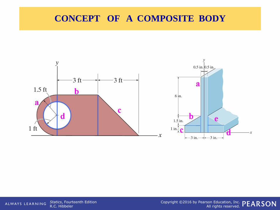
CONCEPT OF A COMPOSITE BODY
Statics, Fourteenth EditionR.C. Hibbeler
Copyright ©2016 by Pearson Education, Inc.All rights reserved.
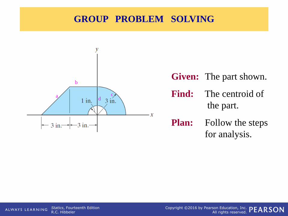
Given: The part shown.
Find: The centroid of
the part.
Plan: Follow the steps
for analysis.
GROUP PROBLEM SOLVING
a
b
cd

Statics, Fourteenth EditionR.C. Hibbeler
Copyright ©2016 by Pearson Education, Inc.All rights reserved.
DEFINITION OF MOMENTS OF INERTIA FOR AREAS, RADIUS OF GYRATION OF AN AREA

Statics, Fourteenth EditionR.C. Hibbeler
Copyright ©2016 by Pearson Education, Inc.All rights reserved.
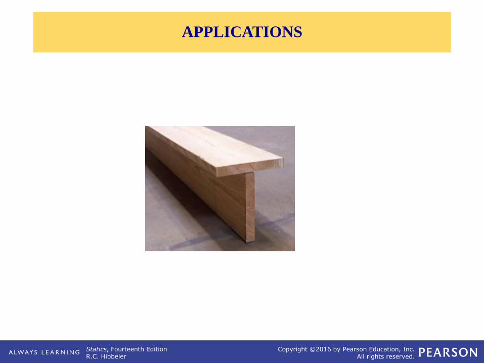
Many structural members like beams and columns have cross
sectional shapes like an I, H, C, etc..
APPLICATIONS

Statics, Fourteenth EditionR.C. Hibbeler
Copyright ©2016 by Pearson Education, Inc.All rights reserved.
1cm
10cm
10cm1cm x
3cm
10cm 3cm
R S
P
(C)(B)(A)
DEFINITION OF MOMENTS OF INERTIA FOR AREAS

Statics, Fourteenth EditionR.C. Hibbeler
Copyright ©2016 by Pearson Education, Inc.All rights reserved.
For the differential area dA, shown in the
figure:
d Ix = y2 dA ,
d Iy = x2 dA , and,
d JO = r2 dA , where JO is the
polar moment of inertia about the pole O or z
axis.
DEFINITION OF MOMENTS OF INERTIA FOR AREAS

Statics, Fourteenth EditionR.C. Hibbeler
Copyright ©2016 by Pearson Education, Inc.All rights reserved.
For simplicity, the area element used has
a differential size in only one direction
(dx or dy). This results in a single
integration and is usually simpler than
doing a double integration with two
differentials, i.e., dx·dy.
MoI FOR AN AREA BY INTEGRATION

Statics, Fourteenth EditionR.C. Hibbeler
Copyright ©2016 by Pearson Education, Inc.All rights reserved.
Given: The shaded area shown in the
figure.
Find: The MoI of the area about the
x- and y-axes.
Plan: Follow the steps given earlier.
EXAMPLE
•
(x,y)

Statics, Fourteenth EditionR.C. Hibbeler
Copyright ©2016 by Pearson Education, Inc.All rights reserved.
PARALLEL-AXIS THEOREM, RADIUS OF GYRATION & MOMENT OF INERTIA FOR COMPOSITE AREAS
Statics, Fourteenth EditionR.C. Hibbeler
Copyright ©2016 by Pearson Education, Inc.All rights reserved.
APPLICATIONS

Statics, Fourteenth EditionR.C. Hibbeler
Copyright ©2016 by Pearson Education, Inc.All rights reserved.
APPLICATIONS (continued)

Statics, Fourteenth EditionR.C. Hibbeler
Copyright ©2016 by Pearson Education, Inc.All rights reserved.
Consider an area with centroid C. The x' and y' axes pass through C. The MoI about the x-axis,
which is parallel to, and distance dy from the x ' axis, is found by using the parallel-axis theorem.
This theorem relates the moment of inertia (MoI) of an
area about an axis passing through the area’s centroid to
the MoI of the area about a corresponding parallel axis.
This theorem has many practical applications, especially
when working with composite areas.
PARALLEL-AXIS THEOREM FOR AN AREA (Section 10.2)

Statics, Fourteenth EditionR.C. Hibbeler
Copyright ©2016 by Pearson Education, Inc.All rights reserved.
PARALLEL-AXIS THEOREM (continued)
Statics, Fourteenth EditionR.C. Hibbeler
Copyright ©2016 by Pearson Education, Inc.All rights reserved.
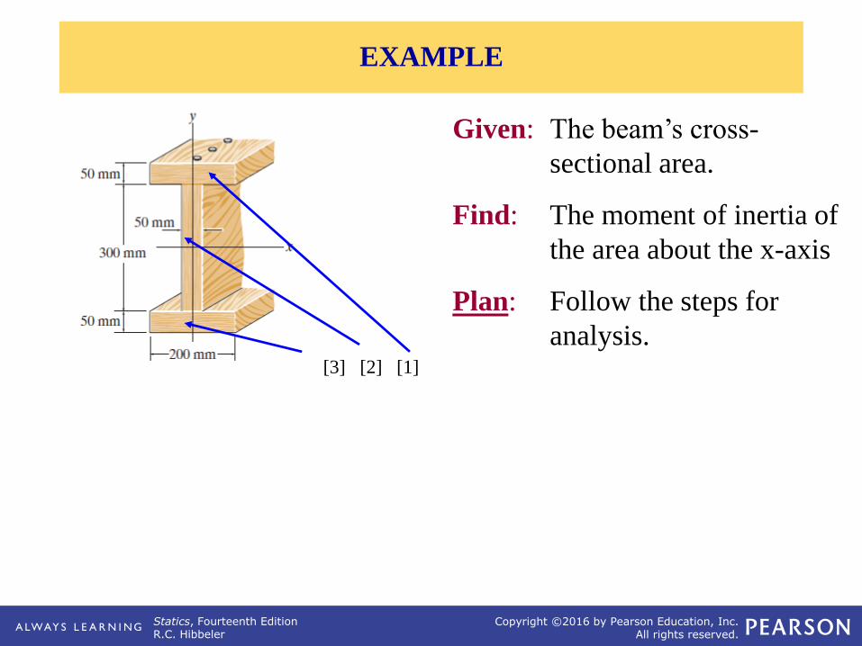
Given: The beam’s cross-
sectional area.
Find: The moment of inertia of
the area about the x-axis
Plan: Follow the steps for
analysis.[3] [2] [1]
EXAMPLE