Embed Size (px)
Citation preview
Statistical Atlas Based Extrapolation of CT Data
Gouthami Chintalapania, Ryan Murphyb, Robert S. Armigerc, Jyri Lepist’od,Yoshito Otakea,Nobuhiko Suganoe, Russell H. Taylora and Mehran Armandc
aDepartment of Computer Science, Johns Hopkins University, Baltimore, USA;bDepartment of Biomedical Engineering, Johns Hopkins University, Baltimore, USA;
c Johns Hopkins University Applied Physics Laboratory, Laurel, USA;dPjhlajalinna Hospital, Tampere, Finland;
e Department of Orthopedic Surgery, Osaka University Graduate School of Medicine, Japan;
ABSTRACT
We present a framework to estimate the missing anatomical details from a partial CT scan with the helpof statistical shape models. The motivating application is periacetabular osteotomy (PAO), a technique fortreating developmental hip dysplasia, an abnormal condition of the hip socket that, if untreated, may lead toosteoarthritis. The common goals of PAO are to reduce pain, joint subluxation and improve contact pressuredistribution by increasing the coverage of the femoral head by the hip socket. While current diagnosis andplanning is based on radiological measurements, because of significant structural variations in dysplastic hips,a computer-assisted geometrical and biomechanical planning based on CT data is desirable to help the surgeonachieve optimal joint realignments. Most of the patients undergoing PAO are young females, hence it is usuallydesirable to minimize the radiation dose by scanning only the joint portion of the hip anatomy. These partialscans, however, do not provide enough information for biomechanical analysis due to missing iliac region. Astatistical shape model of full pelvis anatomy is constructed from a database of CT scans. The partial volume isfirst aligned with the statistical atlas using an iterative affine registration, followed by a deformable registrationstep and the missing information is inferred from the atlas. The atlas inferences are further enhanced by theuse of X-ray images of the patient, which are very common in an osteotomy procedure. The proposed method isvalidated with a leave-one-out analysis method. Osteotomy cuts are simulated and the effect of atlas predictedmodels on the actual procedure is evaluated.
Keywords: atlases, registration, hip dysplasia, CT
1. INTRODUCTION
Developmental hip dysplasia (DDH) or hip dysplasia is a deformation of the hip joint in which the hip socket isshallow leading to instability. Patients exhibiting DDH have an abnormal characterization of the hip joint withrespect to the femoral head, which can cause considerable pain. This condition is more common in young adultsand can progress to osteoarthritis if left untreated. Diagnosis for this condition relies on AP radiographs, butprecise planning can be enhanced by obtaining computed tomography (CT) data around the hip joint.1,2
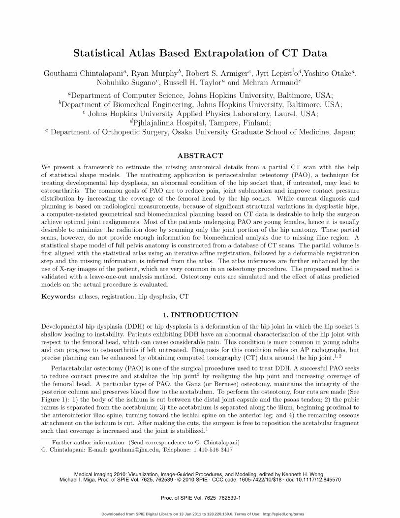
Periacetabular osteotomy (PAO) is one of the surgical procedures used to treat DDH. A successful PAO seeksto reduce contact pressure and stabilize the hip joint3 by realigning the hip joint and increasing coverage ofthe femoral head. A particular type of PAO, the Ganz (or Bernese) osteotomy, maintains the integrity of theposterior column and preserves blood flow to the acetabulum. To perform the osteotomy, four cuts are made (SeeFigure 1): 1) the body of the ischium is cut between the distal joint capsule and the psoas tendon; 2) the pubicramus is separated from the acetabulum; 3) the acetabulum is separated along the ilium, beginning proximal tothe anteroinferior iliac spine, turning toward the ischial spine on the anterior leg; and 4) the remaining osseousattachment on the ischium is cut. After making the cuts, the surgeon is free to reposition the acetabular fragmentsuch that coverage is increased and the joint is stabilized.1
Further author information: (Send correspondence to G. Chintalapani)G. Chintalapani: E-mail: [email protected], Telephone: 1 410 516 3417
Medical Imaging 2010: Visualization, Image-Guided Procedures, and Modeling, edited by Kenneth H. Wong, Michael I. Miga, Proc. of SPIE Vol. 7625, 762539 · © 2010 SPIE · CCC code: 1605-7422/10/$18 · doi: 10.1117/12.845570
Proc. of SPIE Vol. 7625 762539-1
Downloaded from SPIE Digital Library on 13 Jan 2011 to 128.220.160.6. Terms of Use: http://spiedl.org/terms
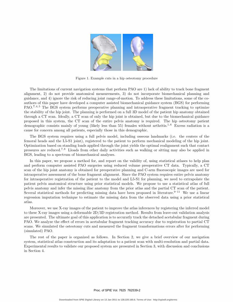
Figure 1. Example cuts in a hip osteotomy procedure
The limitations of current navigation systems that perform PAO are 1) lack of ability to track bone fragmentalignment, 2) do not provide anatomical measurements, 3) do not incorporate biomechanical planning andguidance, and 4) ignore the risk of reducing joint range-of-motion. To address these limitations, some of the co-authors of this paper have developed a computer assisted biomechanical guidance system (BGS) for performingPAO.?, 4, 5 The BGS system performs preoperative planning and intraoperative fragment tracking to optimizethe stability of the hip joint. The planning is performed on a full 3D model of the patient hip anatomy obtainedthrough a CT scan. Ideally, a CT scan of only the hip joint is obtained, but due to the biomechanical guidanceproposed in this system, the CT scan of the entire pelvis anatomy is required. The hip osteotomy patientdemographic consists mainly of young (likely less than 55) females without arthritis.1,6 Excess radiation is acause for concern among all patients, especially those in this demographic.
The BGS system requires using a full pelvis model, including osseous landmarks (i.e. the centers of thefemoral heads and the L5-S1 joint), registered to the patient to perform mechanical modeling of the hip joint.Optimization based on standing loads applied through the joint yields the optimal realignment such that contactpressures are reduced.7,8 Lloads from other daily activities such as walking or sitting may also be applied inBGS, leading to a spectrum of biomechanical analyses.
In this paper, we propose a method for, and report on the validity of, using statistical atlases to help planand perform computer assisted PAO surgeries using reduced volume preoperative CT data. Typically, a CTscan of the hip joint anatomy is obtained for preoperative planning and C-arm fluoroscopic images are used forintraoperative assessment of the bone fragment alignment. Since the PAO system requires entire pelvis anatomyfor intraoperative registration of the patient to the model and L5-S1 for planning, we need to extrapolate thepatient pelvis anatomical structure using prior statistical models. We propose to use a statistical atlas of fullpelvis anatomy and infer the missing iliac anatomy from the prior atlas and the partial CT scan of the patient.Several statistical methods for predicting missing data have been proposed in literature.9–11 We use a linearregression imputation technique to estimate the missing data from the observed data using a prior statisticalatlas.
Moreover, we use X-ray images of the patient to improve the atlas inferences by registering the inferred modelto these X-ray images using a deformable 2D/3D registration method. Results from leave-out validation analysisare presented. The ultimate goal of this application is to accuratly track the detached acetabular fragment duringPAO. We analyze the effect of errors in acetabular fragment tracking accuracy due to registration to partial CTscans. We simulated the osteotomy cuts and measured the fragment transformations errors after for performing(simulated) PAO.
The rest of the paper is organized as follows. In Section 2, we give a brief overview of our navigationsystem, statistical atlas construction and its adaptation to a patient scan with multi-resolution and partial data.Experimental results to validate our proposed system are presented in Section 3, with discussion and conclusionsin Section 4.
Proc. of SPIE Vol. 7625 762539-2
Downloaded from SPIE Digital Library on 13 Jan 2011 to 128.220.160.6. Terms of Use: http://spiedl.org/terms
2. METHODS AND MATERIALS
In this section, we outline the statistical model construction, model adaptation to a new instance, and shapeinference from partial data.
2.1 Periacetabular Osteotomy
The BGS system can be beneficial because it tracks the acetabular fragment and performs biomechanical analysispre- and intraoperatively.?,4, 5 The system requires an accurate intraoperative model-to-patient registration toaccurately track the acetabular fragment through realignment. If the model-to-patient registration is inaccurate,errors in computing biomechanics and measuring the acetabular realignment occur, hampering the usefulness ofBGS; thus, a full pelvic CT scan is performed preoperatively so a more accurate registration can be establishedand biomechanics can be computed. As shown in Figure 2, the BGS system uses an optical tracker to track thetools used during PAO and acquire points on the patient.
Initially, the surgeon digitizes a smattering of points from the ilium and the iliac crest on the operative side.These points are then registered to the model using an Unscented Kalman Filter (UKF) technique, which hasbeen shown to be more robust than traditional Iterative Closest Point (ICP) algorithms.12 Before and after thefragment reorientation, a set of four points are digitized on the acetabular fragment defining the transformationof the fragment in the patient frame. Using the UKF registration, the fragment transformation is redefined in themodel frame and the fragment reorientation has been successfully tracked. Acquiring the fragment transformationin the model frame is crucial to the BGS system so the biomechanics can be accurately computed.
Optical Tracker
Patient Contact
Pressures
BGS
Model to Patient
Registration
Joint contact-pressure
after fragment realignment
Figure 2. Various Components of Computer Assisted Periacetabular Osteotomy5
2.2 Statistical Atlas Construction
A statistical atlas of pelvis anatomy is constructed using the process described by Chintalapani et al.13 In general,the atlas construction process can be divided into three main steps: 1) model representation and construction, 2)model correspondences, and 3) statistical analysis.14 Our model representation consists of a tetrahedral mesh toparameterize anatomical shape and Bernstein polynomials to approximate CT intensities.15,16 Given a trainingdata sets obtained from CT scans of patients, we select a template CT and manually segment and mesh it to
Proc. of SPIE Vol. 7625 762539-3
Downloaded from SPIE Digital Library on 13 Jan 2011 to 128.220.160.6. Terms of Use: http://spiedl.org/terms
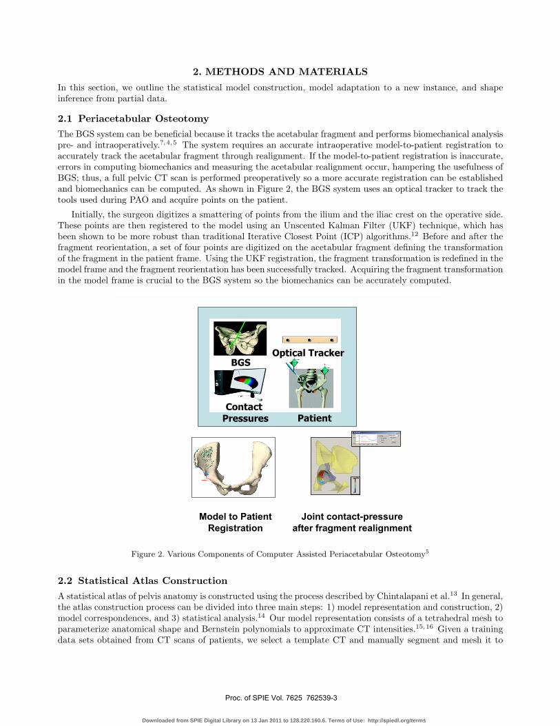
create a template mesh. To establish point correspondences across the training data sets, we use a grayscaledeformable registration method.17 All the data sets in the training sample are registered deformably to thetemplate CT and the resulting deformation field is applied to the template mesh to create mesh instances forthe training data. The vertices of these mesh instances define the point distribution model (PDM) for shapeproperties. Principal component analysis on this PDM results in a shape atlas consisting of an average shaperepresentation and the shape variations in the form of eigenmodes. This shape model is further refined by usingan iterative bootstrapping technique described in.13 Using this method, the atlas is iteratively registered to thetraining CT data sets and updated after each iteration resulting in stable shape variations. Although our atlascan incorporate both the shape and intensity properties, only the surface model of a patient anatomy is usedfor BGS procedure. The rest of the paper, therefore, uses shape statistical models only. Hence, we trim thetetrahedral meshes to extract surface mesh instances of each of the training CT data set.
A surface mesh instance is defined as a set of 3D points in space that define the shape of the anatomical regionof interest, si = [x1, y1, z1;x2, y2, z2; ...xn, yn, zn]. These mesh instances are aligned using procrustes alignmentprocedure to exclude any translation, rotation and scale from the inherent shape variations and vectorized suchthat �si = [x1, y1, z1, x2, y2....zn]. Given a set of such vectorized shape instances, S = {�s1, �s2, ... �sN}, . The averageshape, S can be computed as
S =1N
N∑i=1
�si; (1)
and the covariance matrix, C is
C =1
N − 1{ΔS}{ΔS}T ; ΔS = {�s1 − S, �s2 − S, ..., �sN − S} (2)
The principal components can be obtained by taking SVD decomposition of C,
C = UDV T (3)
where U = {�U1, �U2, ..., �UN−1} are the orthogonal shape modes and D = diag(d1, d2, ..., dN−1) are the singularvalues. The eigenvalues are given as E = {e1 = d2
1, e2 = d22, ..., eN−1 = d2
N−1}Given this low-dimensional parameterization of shape space, we can write any given shape instance as a linear
combination of the orthogonal modes.�s = S + λ ∗ U ; (4)
(a)
(b)
(c)
(d)
(e)
(f)
(g)
Figure 3. DRRs of mean shape and first three principal modes. (a) mean shape (S); (b)-(c) Mode 1(S ± 3e1S1); (d)-(e)
Mode 2 (S ± 3e2S2; (f)-(g) Mode 3 (S ± 3e3S
3)
Proc. of SPIE Vol. 7625 762539-4
Downloaded from SPIE Digital Library on 13 Jan 2011 to 128.220.160.6. Terms of Use: http://spiedl.org/terms
SJ
SI
Observed
Missing
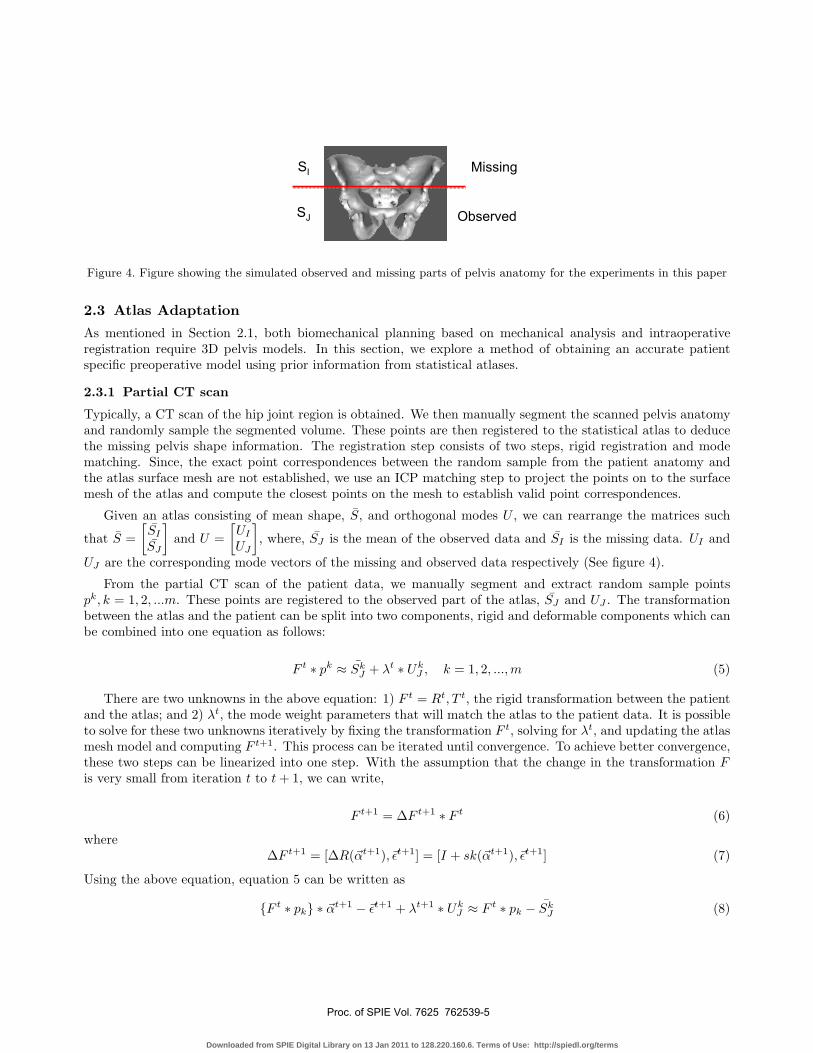
Figure 4. Figure showing the simulated observed and missing parts of pelvis anatomy for the experiments in this paper
2.3 Atlas Adaptation
As mentioned in Section 2.1, both biomechanical planning based on mechanical analysis and intraoperativeregistration require 3D pelvis models. In this section, we explore a method of obtaining an accurate patientspecific preoperative model using prior information from statistical atlases.
2.3.1 Partial CT scan
Typically, a CT scan of the hip joint region is obtained. We then manually segment the scanned pelvis anatomyand randomly sample the segmented volume. These points are then registered to the statistical atlas to deducethe missing pelvis shape information. The registration step consists of two steps, rigid registration and modematching. Since, the exact point correspondences between the random sample from the patient anatomy andthe atlas surface mesh are not established, we use an ICP matching step to project the points on to the surfacemesh of the atlas and compute the closest points on the mesh to establish valid point correspondences.
Given an atlas consisting of mean shape, S, and orthogonal modes U , we can rearrange the matrices such
that S =[SI
SJ
]and U =
[UI
UJ
], where, SJ is the mean of the observed data and SI is the missing data. UI and
UJ are the corresponding mode vectors of the missing and observed data respectively (See figure 4).
From the partial CT scan of the patient data, we manually segment and extract random sample pointspk, k = 1, 2, ...m. These points are registered to the observed part of the atlas, SJ and UJ . The transformationbetween the atlas and the patient can be split into two components, rigid and deformable components which canbe combined into one equation as follows:
F t ∗ pk ≈ SkJ + λt ∗ Uk
J , k = 1, 2, ...,m (5)
There are two unknowns in the above equation: 1) F t = Rt, T t, the rigid transformation between the patientand the atlas; and 2) λt, the mode weight parameters that will match the atlas to the patient data. It is possibleto solve for these two unknowns iteratively by fixing the transformation F t, solving for λt, and updating the atlasmesh model and computing F t+1. This process can be iterated until convergence. To achieve better convergence,these two steps can be linearized into one step. With the assumption that the change in the transformation Fis very small from iteration t to t + 1, we can write,
F t+1 = ΔF t+1 ∗ F t (6)
whereΔF t+1 = [ΔR(�αt+1),�εt+1] = [I + sk(�αt+1),�εt+1] (7)
Using the above equation, equation 5 can be written as
{F t ∗ pk} ∗ �αt+1 − �εt+1 + λt+1 ∗ UkJ ≈ F t ∗ pk − Sk
J (8)
Proc. of SPIE Vol. 7625 762539-5
Downloaded from SPIE Digital Library on 13 Jan 2011 to 128.220.160.6. Terms of Use: http://spiedl.org/terms
We can form a system of linear equations for each k and solve it for �αt+1, �εt+1, λt+1. Having computed theoptimal λ, we can now estimate the missing region as follows.
Sest =
⎡⎣ Sest
I
SestJ
⎤⎦ =
⎡⎣ SI
SJ
⎤⎦ + λ
⎡⎣ UI
UJ
⎤⎦ (9)
The extrapolated patient model Sest consists of errors in both the observed and the missing data parts. Sincewe already have exact information for the observed part from the CT, we replace the predicted observed part
with the true data such that, Sest =[
SestI
StrueJ
]. We then use only the missing/predicted part of the anatomy
for optimization.
2.3.2 X-ray Guidance
Since hip dysplasia is an abnormality of the joint region only, the rest of the pelvis anatomy may or may not beabnormal. Hence, the inferences from the statistical atlas might be error prone and some information about themissing iliac region might be helpful in predicting more accurate estimates. Fluoroscopy is very commonly usedin osteotomy procedures for qualitative analysis. We propose to use intra-operative 2D X-ray images and fusethem with the 3D predicted model. We use an image based 2D/3D registration method described in.18
1. Input: X-ray images/DRRs Ii, where i is the image number/view angle, camera pose parameters (intrinsic andextrinsic) Pi, mean shape S0 and shape modes UI , mean density C0
2. Register the input images to the shape model, rigidly and deformably to estimate the pose and shape parametersrespectively. The output consists of a pose F (R, T, S) and mode weight parameters Φ such that
F, Φ = argmax(F,Φ)
X
i
MI`Ii, DRR
`F.
`SI + ΦUI
´´´(10)
3. Transform the shape model and create DRRs of the registered shape model with mean density and density modes.
Sest =
»Sest
I
StrueJ
–=
»F ∗ `
SI + ΦUI
´
StrueJ
–(11)
3. EXPERIMENTS, RESULTS AND DISCUSSION
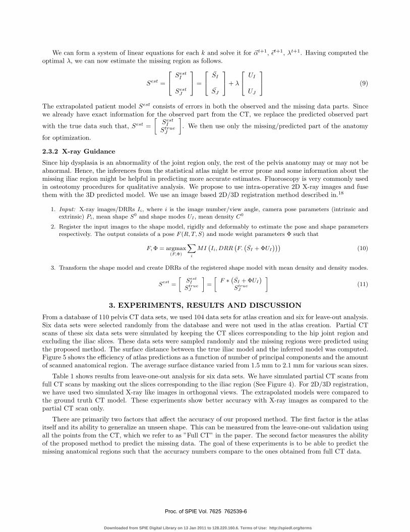
From a database of 110 pelvis CT data sets, we used 104 data sets for atlas creation and six for leave-out analysis.Six data sets were selected randomly from the database and were not used in the atlas creation. Partial CTscans of these six data sets were simulated by keeping the CT slices corresponding to the hip joint region andexcluding the iliac slices. These data sets were sampled randomly and the missing regions were predicted usingthe proposed method. The surface distance between the true iliac model and the inferred model was computed.Figure 5 shows the efficiency of atlas predictions as a function of number of principal components and the amountof scanned anatomical region. The average surface distance varied from 1.5 mm to 2.1 mm for various scan sizes.
Table 1 shows results from leave-one-out analysis for six data sets. We have simulated partial CT scans fromfull CT scans by masking out the slices corresponding to the iliac region (See Figure 4). For 2D/3D registration,we have used two simulated X-ray like images in orthogonal views. The extrapolated models were compared tothe ground truth CT model. These experiments show better accuracy with X-ray images as compared to thepartial CT scan only.
There are primarily two factors that affect the accuracy of our proposed method. The first factor is the atlasitself and its ability to generalize an unseen shape. This can be measured from the leave-one-out validation usingall the points from the CT, which we refer to as ”Full CT” in the paper. The second factor measures the abilityof the proposed method to predict the missing data. The goal of these experiments is to be able to predict themissing anatomical regions such that the accuracy numbers compare to the ones obtained from full CT data.
Proc. of SPIE Vol. 7625 762539-6
Downloaded from SPIE Digital Library on 13 Jan 2011 to 128.220.160.6. Terms of Use: http://spiedl.org/terms
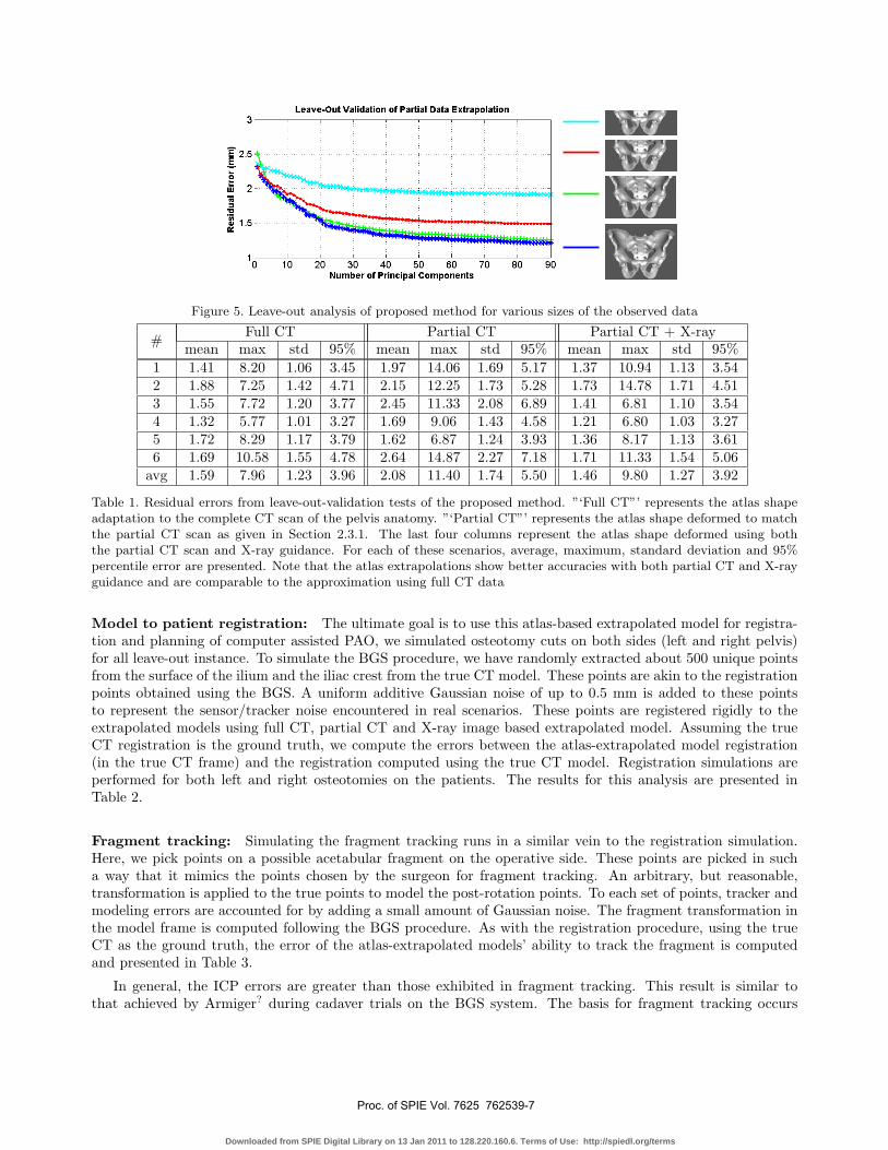
Figure 5. Leave-out analysis of proposed method for various sizes of the observed data
# Full CT Partial CT Partial CT + X-raymean max std 95% mean max std 95% mean max std 95%
1 1.41 8.20 1.06 3.45 1.97 14.06 1.69 5.17 1.37 10.94 1.13 3.542 1.88 7.25 1.42 4.71 2.15 12.25 1.73 5.28 1.73 14.78 1.71 4.513 1.55 7.72 1.20 3.77 2.45 11.33 2.08 6.89 1.41 6.81 1.10 3.544 1.32 5.77 1.01 3.27 1.69 9.06 1.43 4.58 1.21 6.80 1.03 3.275 1.72 8.29 1.17 3.79 1.62 6.87 1.24 3.93 1.36 8.17 1.13 3.616 1.69 10.58 1.55 4.78 2.64 14.87 2.27 7.18 1.71 11.33 1.54 5.06
avg 1.59 7.96 1.23 3.96 2.08 11.40 1.74 5.50 1.46 9.80 1.27 3.92
Table 1. Residual errors from leave-out-validation tests of the proposed method. ”‘Full CT”’ represents the atlas shapeadaptation to the complete CT scan of the pelvis anatomy. ”‘Partial CT”’ represents the atlas shape deformed to matchthe partial CT scan as given in Section 2.3.1. The last four columns represent the atlas shape deformed using boththe partial CT scan and X-ray guidance. For each of these scenarios, average, maximum, standard deviation and 95%percentile error are presented. Note that the atlas extrapolations show better accuracies with both partial CT and X-rayguidance and are comparable to the approximation using full CT data
Model to patient registration: The ultimate goal is to use this atlas-based extrapolated model for registra-tion and planning of computer assisted PAO, we simulated osteotomy cuts on both sides (left and right pelvis)for all leave-out instance. To simulate the BGS procedure, we have randomly extracted about 500 unique pointsfrom the surface of the ilium and the iliac crest from the true CT model. These points are akin to the registrationpoints obtained using the BGS. A uniform additive Gaussian noise of up to 0.5 mm is added to these pointsto represent the sensor/tracker noise encountered in real scenarios. These points are registered rigidly to theextrapolated models using full CT, partial CT and X-ray image based extrapolated model. Assuming the trueCT registration is the ground truth, we compute the errors between the atlas-extrapolated model registration(in the true CT frame) and the registration computed using the true CT model. Registration simulations areperformed for both left and right osteotomies on the patients. The results for this analysis are presented inTable 2.
Fragment tracking: Simulating the fragment tracking runs in a similar vein to the registration simulation.Here, we pick points on a possible acetabular fragment on the operative side. These points are picked in sucha way that it mimics the points chosen by the surgeon for fragment tracking. An arbitrary, but reasonable,transformation is applied to the true points to model the post-rotation points. To each set of points, tracker andmodeling errors are accounted for by adding a small amount of Gaussian noise. The fragment transformation inthe model frame is computed following the BGS procedure. As with the registration procedure, using the trueCT as the ground truth, the error of the atlas-extrapolated models’ ability to track the fragment is computedand presented in Table 3.
In general, the ICP errors are greater than those exhibited in fragment tracking. This result is similar tothat achieved by Armiger? during cadaver trials on the BGS system. The basis for fragment tracking occurs
Proc. of SPIE Vol. 7625 762539-7
Downloaded from SPIE Digital Library on 13 Jan 2011 to 128.220.160.6. Terms of Use: http://spiedl.org/terms
Partial CT
Full CT
Partial CT +
X-ray Images
0mm
3mm
6mm
Figure 6. Distribution of surface registration errors between the atlas and full CT, partial CT and partial CT combinedwith X-ray images
# Full CT Partial CT Partial CT + X-rayrot trans mean max rot trans mean max rot trans mean max(◦) (mm) (mm) (mm) (◦) (mm) (mm) (mm) (◦) (mm) (mm) (mm)
1 2.63 1.03 1.68 5.86 4.23 2.17 2.05 7.55 2.56 2.73 1.65 5.862 1.29 0.97 1.42 5.56 2.62 3.39 1.77 7.15 2.18 3.90 1.85 8.263 1.66 3.58 1.46 5.94 8.37 6.27 1.87 6.41 3.06 3.92 1.50 5.874 0.87 0.91 1.21 4.16 2.00 2.32 1.64 5.96 1.42 2.64 1.46 6.355 1.27 1.09 0.95 3.68 4.96 5.87 1.61 5.47 2.20 1.87 1.22 4.536 1.64 1.97 1.58 6.93 4.32 4.12 1.84 8.75 1.46 2.74 1.44 6.17
avg 1.56 1.59 1.38 5.35 4.41 4.02 1.79 6.88 2.14 2.96 1.52 6.16
Table 2. Model to patient ICP registration errors
in the patient (tracker) frame, which means there is no associated model error; whereas the model-to-patientregistration errors include both model and tracker noise. Although the fragment transformation is subsequentlytransformed from patient space into model space, the errors in the model-to-patient registration will not beexacerbated.
4. CONCLUSIONS
In this paper, we have explored the application of statistical atlases in peri-acetabular osteotomy procedures. Theprior atlas of full pelvis anatomy is fused with the preoperative CT scan of the hip joint and the intra-operativeX-ray images to predict the missing pelvis anatomy. Simulation results show that the accuracy of the atlasextrapolated model is comparable to the full CT model, and has improved when X-ray images are used. Theaverage surface distance between the extrapolated model and the true CT is 1.46 mm. We have also simulatedosteotomy procedures on the leave-out datasets and studied the implications of the extrapolated models withrespect to the patient to CT registration and fragment tracking. An average fragment tracking error of 0.37◦ inrotation and 2.63 mm in translation is reported.
Proc. of SPIE Vol. 7625 762539-8
Downloaded from SPIE Digital Library on 13 Jan 2011 to 128.220.160.6. Terms of Use: http://spiedl.org/terms
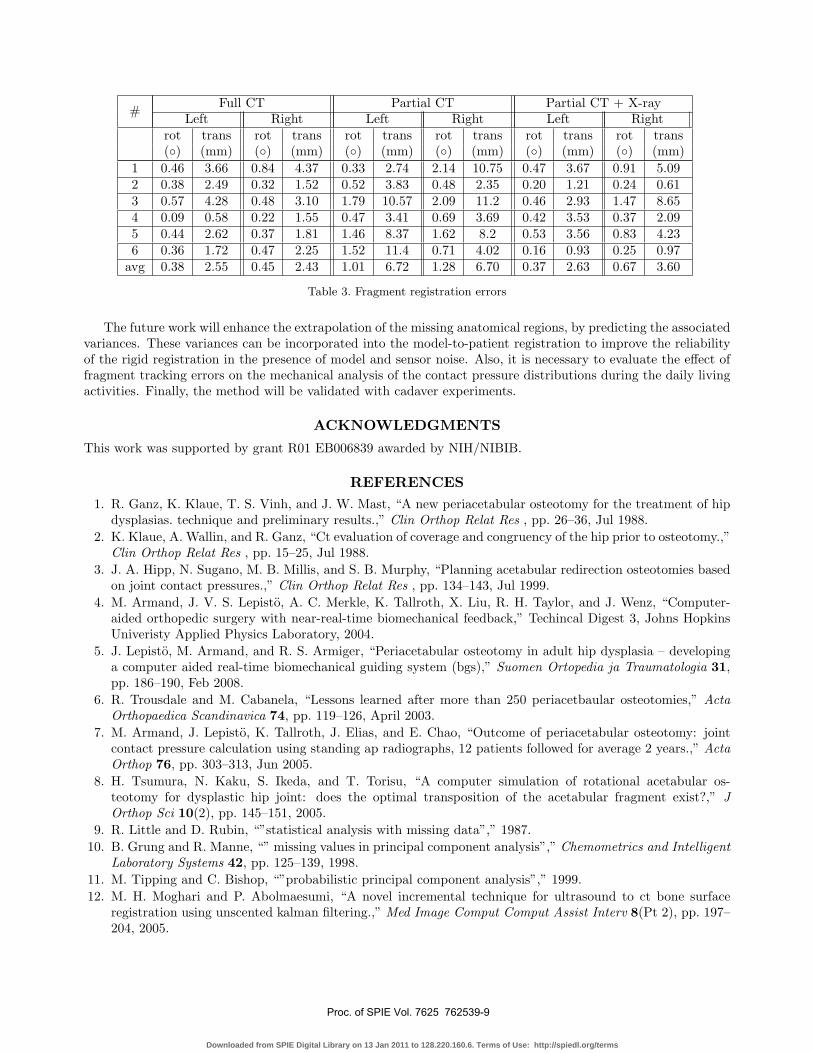
# Full CT Partial CT Partial CT + X-rayLeft Right Left Right Left Right
rot trans rot trans rot trans rot trans rot trans rot trans(◦) (mm) (◦) (mm) (◦) (mm) (◦) (mm) (◦) (mm) (◦) (mm)
1 0.46 3.66 0.84 4.37 0.33 2.74 2.14 10.75 0.47 3.67 0.91 5.092 0.38 2.49 0.32 1.52 0.52 3.83 0.48 2.35 0.20 1.21 0.24 0.613 0.57 4.28 0.48 3.10 1.79 10.57 2.09 11.2 0.46 2.93 1.47 8.654 0.09 0.58 0.22 1.55 0.47 3.41 0.69 3.69 0.42 3.53 0.37 2.095 0.44 2.62 0.37 1.81 1.46 8.37 1.62 8.2 0.53 3.56 0.83 4.236 0.36 1.72 0.47 2.25 1.52 11.4 0.71 4.02 0.16 0.93 0.25 0.97
avg 0.38 2.55 0.45 2.43 1.01 6.72 1.28 6.70 0.37 2.63 0.67 3.60
Table 3. Fragment registration errors
The future work will enhance the extrapolation of the missing anatomical regions, by predicting the associatedvariances. These variances can be incorporated into the model-to-patient registration to improve the reliabilityof the rigid registration in the presence of model and sensor noise. Also, it is necessary to evaluate the effect offragment tracking errors on the mechanical analysis of the contact pressure distributions during the daily livingactivities. Finally, the method will be validated with cadaver experiments.
ACKNOWLEDGMENTS
This work was supported by grant R01 EB006839 awarded by NIH/NIBIB.
REFERENCES1. R. Ganz, K. Klaue, T. S. Vinh, and J. W. Mast, “A new periacetabular osteotomy for the treatment of hip
dysplasias. technique and preliminary results.,” Clin Orthop Relat Res , pp. 26–36, Jul 1988.2. K. Klaue, A. Wallin, and R. Ganz, “Ct evaluation of coverage and congruency of the hip prior to osteotomy.,”
Clin Orthop Relat Res , pp. 15–25, Jul 1988.3. J. A. Hipp, N. Sugano, M. B. Millis, and S. B. Murphy, “Planning acetabular redirection osteotomies based
on joint contact pressures.,” Clin Orthop Relat Res , pp. 134–143, Jul 1999.4. M. Armand, J. V. S. Lepisto, A. C. Merkle, K. Tallroth, X. Liu, R. H. Taylor, and J. Wenz, “Computer-
aided orthopedic surgery with near-real-time biomechanical feedback,” Techincal Digest 3, Johns HopkinsUniveristy Applied Physics Laboratory, 2004.
5. J. Lepisto, M. Armand, and R. S. Armiger, “Periacetabular osteotomy in adult hip dysplasia – developinga computer aided real-time biomechanical guiding system (bgs),” Suomen Ortopedia ja Traumatologia 31,pp. 186–190, Feb 2008.
6. R. Trousdale and M. Cabanela, “Lessons learned after more than 250 periacetbaular osteotomies,” ActaOrthopaedica Scandinavica 74, pp. 119–126, April 2003.
7. M. Armand, J. Lepisto, K. Tallroth, J. Elias, and E. Chao, “Outcome of periacetabular osteotomy: jointcontact pressure calculation using standing ap radiographs, 12 patients followed for average 2 years.,” ActaOrthop 76, pp. 303–313, Jun 2005.
8. H. Tsumura, N. Kaku, S. Ikeda, and T. Torisu, “A computer simulation of rotational acetabular os-teotomy for dysplastic hip joint: does the optimal transposition of the acetabular fragment exist?,” JOrthop Sci 10(2), pp. 145–151, 2005.
9. R. Little and D. Rubin, “”statistical analysis with missing data”,” 1987.10. B. Grung and R. Manne, “” missing values in principal component analysis”,” Chemometrics and Intelligent
Laboratory Systems 42, pp. 125–139, 1998.11. M. Tipping and C. Bishop, “”probabilistic principal component analysis”,” 1999.12. M. H. Moghari and P. Abolmaesumi, “A novel incremental technique for ultrasound to ct bone surface
registration using unscented kalman filtering.,” Med Image Comput Comput Assist Interv 8(Pt 2), pp. 197–204, 2005.
Proc. of SPIE Vol. 7625 762539-9
Downloaded from SPIE Digital Library on 13 Jan 2011 to 128.220.160.6. Terms of Use: http://spiedl.org/terms

13. G. Chintalapani, L. Ellingsen, O. Sadowsky, J. Prince, and R. Taylor, “Statistical atlases of bone anatomy:Construction, iterative improvement and validation,” in MICCAI, 4791/2007, pp. 499–506, 2007.
14. T. Cootes, C. Taylor, D. Cooper, and J. Graham, “” active shape models - their training and application”,”Computer Vision Image Understanding 61(1), pp. 38–59, 1995.
15. J. Yao, A Statistical Bone Density Atlas and Deformable Medical Image Registration. PhD thesis, The JohnsHopkins University, 2002.
16. O. Sadowsky, Image Registration and Hybrid Volume Reconstruction of Bone Anatomy Using a StatisticalShape Atlas. PhD thesis, The Johns Hopkins University, 2008.
17. L. Ellingsen and J. Prince, “Deformable registration of ct pelvis images using mjolnir,” in IEEE 7th NordicSignal Processing Symposium (NORSIG), 2006.
18. O. Sadowsky, G. Chintalapani, and R. Taylor, “Deformable 2d-3d registration of the pelvis with a limitedfield of view, using shape statistics,” in MICCAI, 4791/2007, pp. 519–526, 2007.
Proc. of SPIE Vol. 7625 762539-10
Downloaded from SPIE Digital Library on 13 Jan 2011 to 128.220.160.6. Terms of Use: http://spiedl.org/terms


![GlossaryOfJobDescriptions RHT 2013[1]](https://img.pdfslide.net/doc/110x75/577cc6bf1a28aba7119f0de2/glossaryofjobdescriptions-rht-20131.jpg)