Embed Size (px)
Citation preview

Status on SuperB effort
Frascati, March 16, 2006
P. Raimondi

Outline
• Basic Concepts (March-Sept,2005)• Parameters and layout optimization based on a
High-Disrupted regime (Nov, 2005)• Parameters and layout optimization for a
Minimal-Disrupted regime (Jan, 2005)• Layout for a Ring Collider with Linear Collider
Parameters• Conclusions (4 slides)• Action items
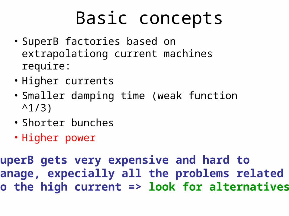
Basic concepts• SuperB factories based on extrapolationg
current machines require:
• Higher currents
• Smaller damping time (weak function ^1/3)
• Shorter bunches
• Higher power
SuperB gets very expensive and hard tomanage, expecially all the problems relatedto the high current => look for alternatives

• Basic Idea comes from the ATF2-FF experiment
In the proposed experiment it seems possible to acheive spot sizes at the focal point of about 2um*20nm at very low energy (1 GeV), out from the damping ring
• Rescaling at about 10GeV/CM we should get sizes of about 1m*10nm =>
• Is it worth to explore the potentiality of a Collider based on a scheme similar to the Linear Collider one
Idea presented at the Hawaii workshop on Super-B factory on March-2005
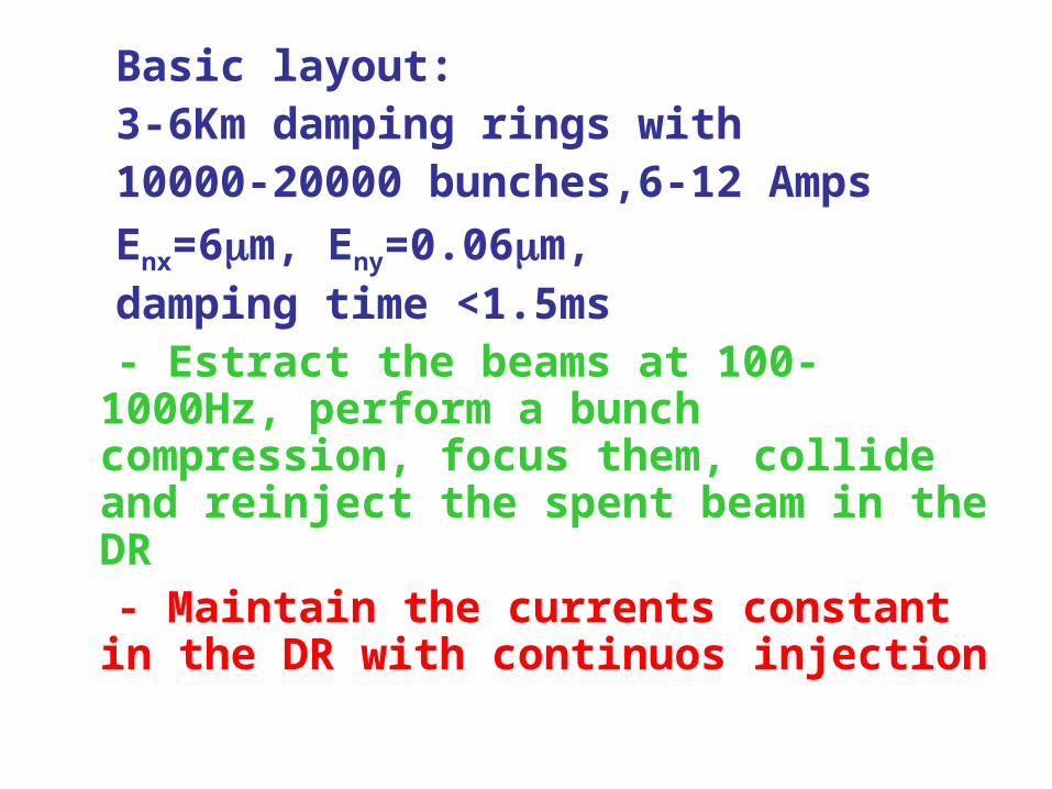
Basic layout: 3-6Km damping rings with 10000-20000 bunches,6-12 Amps Enx=6m, Eny=0.06m, damping time <1.5ms - Estract the beams at 100-
1000Hz, perform a bunch compression, focus them, collide and reinject the spent beam in the DR
- Maintain the currents constant in the DR with continuos injection

LinearB scheme
IPLER Bunch compressor and FF
HER Bunch compressor and FF
LERHER
Overall rings lenght about 6Km,Collision frequency about 120Hz*10000bunch_trains=1.200MHzBunch train stays in the rings for 8.3msec, then is extracted, compressed and focused. After the collision is reinjected in its ring
LER injection Her injection

Scaling laws to optimize the IP parameters
• Disruption:
• Luminosity
• Energy spread:
yx
NL
2
yx
zN
D
zx
E
N
2
2
Decrease z + decrease NIncrease spotsize
Increase NDecrease spotsize
Increase z + decrease NIncrease spotsize
Contraddicting requests!

Luminosity• The luminosity for a linear collider is:
L=Hd Np P / 4 E x y
Hd : disruption enhancement P : average beam power
• For a storage ring is:
L=K(1+r) y EI / y
I : beam current
y : vertical tune shift

• Instead of being a limitation, Beam-Beam interaction might help to increase the luminosity, we should find a suitable parameters set:
stable collisions, reasonable outgoing emittances and energy
spread• Almost linear relation between damping time and
luminosity• Average current through the detector 10-100
times smaller than in the rings (10-100 mAmps)• Rings, althought with a parameter set very
similar to the LC ones, have still to handle a lot more current and more radiation from increased damping
• A lot of the limitations of both kind of colliders are gone. Worth to explore the concept at least with very preliminary calculations and simulations

A lot of homework done in collaboration at SLAC and at the LNF for a few months =>
Leading to a workshop held on Nov,11-12 2005 in Frascati to investigate and optimize the scheme and the feasibility of the different subsystems

0.00
200.00
400.00
600.00
800.00
1000.00
1200.00
1400.00
1600.00
0.8
1
1.2
1.4
1.6
1.8
2
2.2
2.4
5000 10000 15000 20000 25000 30000 35000
Dy
LER
Dy
HER HD
Dy
HD
# bunches
15.7
Npart
(x1010
)
7.9 5.2 4 3.1
Luminosity & E vs N. of bunches at fixed total current = 7.2 A (6.2 Km ring)
5.0 1035
1.0 1036
1.5 1036
2.0 1036
2.5 1036
3.0 1036
0
20
40
60
80
100
120
5000 10000 15000 20000 25000 30000 35000
Lg
LD
cm E
# bunches
15.7
Npart
(x1010
)
7.9 5.2 4 3.1
Energy spread
Working point
D
Study by M. Biagini

Horizontal Collision Vertical collision
Effective horizontal size during collision about 10 times smaller, vertical size 10 times larger
Simulation by D.SchulteFirst attempt

Horizontal phase after the collision
Vertical phase after the collision
IP Parameters set considered at the workshop causedlarge increase of the emittance due to the collision:
Exout/Exin=12 Eyout/Etin=300 M. Biagini studies

Reference geometry• 4x7GeV• 10000 bunches at 1011 = 10A• 476 MHz at 0.63 m spacing• Two damping rings per ring at full energy
– 3000 m damping ring at 3.7 msec damping– 3000 m damping ring at 4.6 msec damping time
• 120 Hz collisions for 8.3 msec cycle time• Assume two damping times between collisions
sum 8.3 msec• 4GeV: 20 MeV/turn, Pwall =400 MW• 7 GeV: 35 MeV per turn, Pwall=700 MW• Total power = 1100 MW

How to reduce the power(1st attempt)
• Use SC linacs to recover energy• Use lower energy damping rings to reduce
synchrotron radiation• No electron damping ring• Make electrons fresh every cycle
– Damping time means time to radiate all energy– Why not make a fresh beam if storage time is
greater than 1 damping time
J. Seeman proposal

Linear Super B schemes with accelerationand energy recovery
e- Gun2GeVe+ DR IP
5GeV e+ SC Linac
e- Dump7GeV e+
4 GeV e-
4GeV e- SC Linac
2 GeV e+ injection
2 GeV Linac1.5 GeV Linac 1.5 GeV Linac
Linac
Damping Rings2 GeV
Linac
e+ Gun e- Gun

Power budget with this schemes
• 4 x 7 GeV• 10000 bunches at 1011 = 6A(e+)/12A(e-)• Damping ring RFfreq= 500 MHz at 0.6 m spacing• SC linac for 5 GeV e- with low emittance photo-gun• 5.5GeV SC linac, frequency = 1300 MHz • Damping ring for 2 GeV positrons with wigglers
– 3000 m damping ring at 3.7 msec damping– 3000 m damping ring at 4.6 msec damping time
• 120 Hz collisions for 8.3 msec cycle time• Assume two damping times between collisions sum 8.3 msec• Recycle energy for both beams in SC linac structures• 2GeV ring: 10 MeV/turn, Pwall =100 MW• Accelerate 1011 particles to 5 GeV (e+) and also 4 GeV (e-)• Without energy recovery, beam generation power = 211 MW• Assume energy recovery is 99% efficient, needed power = 2 MW• Cyrogenic power (1W/MeV) Pwall = 5 kW*1000=5MW• Total power = 110 MW
J. Seeman study

Progress in design optimization after the 1° SuperB workshop
Between December-2005 and March-2006 a lot of studies have been made in order to understand what are the sources of the blow-ups in the collision and how to minimize then.
Power requirements could be greatly reduced if collision is less disruptive
Search for a trade off between luminosity delivered in one collision and power spent for each collision
Search for the simplest and more economic solution

x=10m y=10nm z=250um
x=33mm y=1mm
x=3.3*10-9 y=10-13
Lnorm=Ld/log(y_out/y_in)=2.27 at Npart=2.5*1010
Introduced the luminosity merit function: Lnorm=L/log(ey_out/ey_in) => Luminosity per energy cost
Luminosity vs bunch charge for a given set of IP parameters
Outgoing/incoming emittances ratiovs bunch charge for a given set of IP parameters
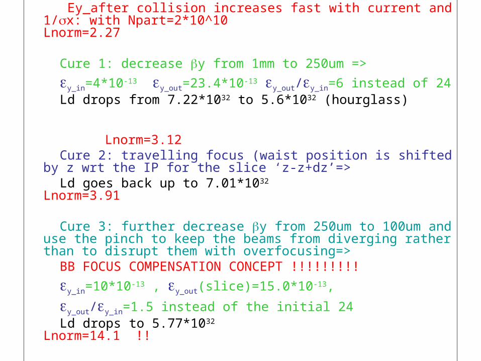
Ey_after collision increases fast with current and 1/x: with Npart=2*10^10 Lnorm=2.27
Cure 1: decrease y from 1mm to 250um =>
y_in=4*10-13 y_out=23.4*10-13 y_out/y_in=6 instead of 24 Ld drops from 7.22*1032 to 5.6*1032 (hourglass) Lnorm=3.12 Cure 2: travelling focus (waist position is shifted by z wrt
the IP for the slice ‘z-z+dz’=> Ld goes back up to 7.01*1032 Lnorm=3.91
Cure 3: further decrease y from 250um to 100um and use the pinch to keep the beams from diverging rather than to disrupt them with overfocusing=>
BB FOCUS COMPENSATION CONCEPT !!!!!!!!!
y_in=10*10-13 , y_out(slice)=15.0*10-13,
y_out/y_in=1.5 instead of the initial 24 Ld drops to 5.77*1032 Lnorm=14.1 !!

With travel focus
Without travel focus
Horizontal collisions in a round beam case

3 planes slice emittances after the collision (round case), each color is a different slice (red head of the bunch, black tail)
Without Travel Focus
y_out/y_in=3
With Travel Focus
y_out/y_in=1.1

• BB focusing compensation works almost linearly increasing the beam charge and vertical size by the same amount (flat case):
x=10um y=10nm z=250um
x=10mm y=0.1mm
x=10*10-9 y=10*10-13
Npart=2.5*1010
Ld=5.77*1032
y_out/y_in=1.5
x=10um y=20nm z=250um
x=10mm y=0.1mm
x=10*10-9 y=40*10-13
Npart=5.0*1010
Ld=11.5*1032
y_out/y_in=1.5

• BB focusing compensation is a function only of the product x*y and not the aspect ratio, this can be chosen to optimize the emittance ratio
• Needs z as small as possible and x large to reduce energy spread from beamsstralung
• Horizontal size does not change during the collision, could be dominated by dispersion to make the ‘luminosity energy spread’ very small (monochromator)
x=5.4um y=36nm z=200um
x=10mm y=0.08mm
x=3*10-9 y=17*10-12 0.6% coupling
Npart=6.0*1010
Ld=1.75*1033 e_beamsstralung=2MeV
y_out/y_in=1.5
600Hz*10000bunches => I+=4amps in the Damping Ring
L=1036

• Round beams compressed, with collisions every 50 turns, BB-compensation on
• Flat beams compressed with collisions every 50 turns, BB-compensation on (1)
• Flat beams compressed colliding in the rings, BB-compensation on (2)
• Flat beams uncompressed colliding in the rings, Crab-Focusing on (3)
Analized Configurations, in the “Small Disruption Regime”

Round Flat (1) Flat (2) Flat (3)Sigx* m 0.9 30 (1 betatron) 30 (1 betatron) 2.67Etax mm 0.0 +-1.5 +-1.5 0.0Sigy nm 900 12.6 12.6 12.6Betx mm 0.55 2.5 2.5 17.8Bety mm 0.55 0.080 0.080 0.080Sigz_IP mm 0.8 0.100 0.100 4.0Sige_IP 1.0e-3 2.0e-2 2.0e-2 1.0e-3Sige_Lum 0.7e-3 1.0e-3 1.0e-3 0.7e-3Emix nm
1.5 0.4 0.4 0.4
Emiy nm
1.5 0.002 0.002 0.002
Emiz m 0.8 2.0 2.0 4.0Cross_angle mrad Optional Optional 2*25 2*25Sigz_DR mm 0.8 4.0 4.0 4.0Sige_DR 1.0e-3 0.5e-3 0.5e-3 1.0e-3Np 10e10 7.0 7.0 1.0 2.0Nbunches 10000 10000 5000 5000DR_length km 6.0 6.0 3.0 3.0Damping_time msec 10 10 10 10Nturns_betwe_coll 50 50 1 1Collision freq MHz 10.0 10.0 500 500Lsingleturn 1e36 1.3 1.3 1.2 0.8
Lmultiturn 1e36 0.9 0.9 1.0 1.2

Round case in multi-turn regime with Np=7*1010, Nbunches=10000 (6Km ring) BB compensation with travel focus in both planes
z=0.8mm
e=5MeV e/e=10-3
z=0.8um Stored time between collision=1msec=50turns
Lmultiturn=0.9*1036 Lsingleturn=1.3*1036
Unfortunately the longitudinal emittance required is smaller than what the ring can get, the monochromator does not work because the phases mix during the collision, so the energy correlation whases out E.Paoloni studies

Flat case in multi-turn regime with Np=7*1010
Nbunches=10000 (6Km ring)
Travel focus in vertical plane only
x=1.5mm (opposite sign for the two beams), x*=30m
z=100m z=4mm in DR
e=100MeV e/e=2*10-2 e/e=5*10-4 in DR
e_Luminosity=7MeV
x=0.4nm x_norm=4m
y=0.002nm y_norm=20pm
z=2.0m Stored time between collision=1msec=50turns
Lmultiturn=1.0*1036 (Lsingleturn=1.2*1036) FF with large energy spread tricky

Multiturn Simulation for flat case6Km ring,Np= 7*1010,10000 bunchescoll_freq=1Khz*10000 Lmultiturn=1036

Compressor
Compressor Decompressor
DeCompressor
IP
OptionalAccelerationand deceleration
OptionalAccelerationand deceleration
FF FF
ILC ring with ILC FFILC compressorColliding every 50 turnAcceleration optionalCrossing angle optional
Now the acceleration is not needed anymore in order to reduce the power
Simplified layout in the Small Disruption Regime

In summary, the small disruption regime requires:
small sigmaz (=> large sigmae from compressor)
big sigmax
small sigmay (for luminosity) and betay
BB-compensation by traveling focus
all the requirements do fit togheter with the monocromator
it simultaneneously enlarge sigmax and decrease the
luminosity energy spread
moreover since the natural horizontal emittance is small,
the emittance ratio of about 0.5% ensure the small sigmay

• Equilibrium Emittance Vertical blowup about 60%• Blowup as function of beam currents almost linear• Blowup as function of damping time goes like Tau1/3
• Reducing the bunch charge by a factor 6 (1010), equilibrium blowup decreases to 10%
• Reducing the damping by a factor 50 (collision every turn) equilibrium blowup increases by a factor 4 (501/3)
• Final Blowup in this case is about 40%• Geometric Luminosity decreases by a factor 36 due to
less charge and increases by a factor 50 for increased collision rate
• With the same parameters but colliding in the ring (bunch compressor and FF in the ring), we get:
L=1036 with Npart=1010 and L=4*1036 with N=2*1010
Scaling the parametrs to an every-turn colliding machine

Flat case Collisions in Ring Compressed Bunches
Nbunches=5000 (3Km ring)
BB compensation with travel focus in vertical plane
e=100MeV e/e=2*10-2 e_Luminosity=10MeV
x=0.4nm x_norm=4m
y=0.002nm y_norm=20pm
z=2.0m
Stored time between collision=10sec=0.001Tau=1turn
Lmultiturn=1.0*1036 (Lsingleturn=1.2*1036) with Npart=1010
Lmultiturn=3.8*1036 with Npart=2*1010
FF with large energy spread tricky
Bunch compressor in the ring tricky

Multiturn simulations for Flat,Compressed beamsCollisions in the Ring3Km Ring,Npart= 2*1010,5000 bunchesColl_freq=100Khz*5000Lmultiturn=3.8*1036

Compressor Compressor
Decompressor Decompressor
IPFF FF
ILC ring with ILC FFILC Compressor, 0.4GeV S-Band or 1GeV L-BandCrossing angle optional
Simplified layout in the Small Disruption Regime Collisions every Turn

Do we need to compress the bunches?
Sz Sz Sx
SzSx Sx
All cases have the same luminosity(2) has longer bunch, longitudinal sovrapposition happens in the same area as in (1)(3) has longer bunch and smaller x
At any given time (2) and (3) have the same overlapping region
1) Standardshort bunches
2) Crab crossing with no crossing angle
3) Crossing angle
Overlapping region
Overlapping region
Overlapping region

Colliding every turn very promising but requires a bunch compressors and a decompressor in the ring (about 400MeV S-band)
In principle not needed to compress the beams if we collide with a crossing angle such as:
z*xcross=24m (same projected horizontal size)
x/xcross=100m (same effective longitudinal interaction region)
y=12.6nm, y=80um like in the compressed case These parameters gives the same geometric luminosity like the
compressed case:
If z=4mm we need:
x_cross=6mrad, x=0.6um However now beam-beam worsened because the beams
see each other also at non-minimum betay locations
Scaling the parameters for an every-turn colliding machine, with Uncompressed Bunches

With large crossing angle X and Z quanties are swapped Very important!!!
Sz
Sx
z
x
Sx/
Sz*
e-e+

Easy way to decrease the ‘Long Range Beam Beam’ is to increase the crossing angle by a factor 4 at a direct luminosity cost of a factor 4:
xcrossing_angle=2*24mrad
x=2.4m
This still gives a luminosity of 1.2*1036 with N=2*1010 if the vertical blowup were none
Unfortunately the blowup is still large and the vertical equilibrium emittance is about 60 times larger, with the equilibrium luminosity around 1.2*1035

Second way to decrease the ‘Long Range Beam Beam’ is to apply the travel focus idea, but now has to be applied in the transverse plane since x and z are swapped.
Vertical waist position in z is a function of x: Zy_waist(x)=x/Crabbed waist All components of the beam collide at a
minimum y => the ‘hour glass’ is reduced, the geometric luminosity is higher the bb effects are greatly reduced

Vertical waist has to be a function of x:
Z=0 for particles at –x (- x/2 at low current)
Z= x/ for particles at + x (x/2 at low current)
2Sz
2Sx
z
x
2Sx/
2Sz*
e-e+

Crabbed waist: - All components of the beam collide at a
minimum betay
- The ‘hour glass’ is reduced and the geometric luminosity is higher
- The bb effect in the section were the beams do overlap is reduced
- The bb effect in the sections were the beams do not overlap is greatly reduced
From tracking, the blowup at the equilibrium goes down to just a factor 2!!!, with a luminosity of about 0.8*1036
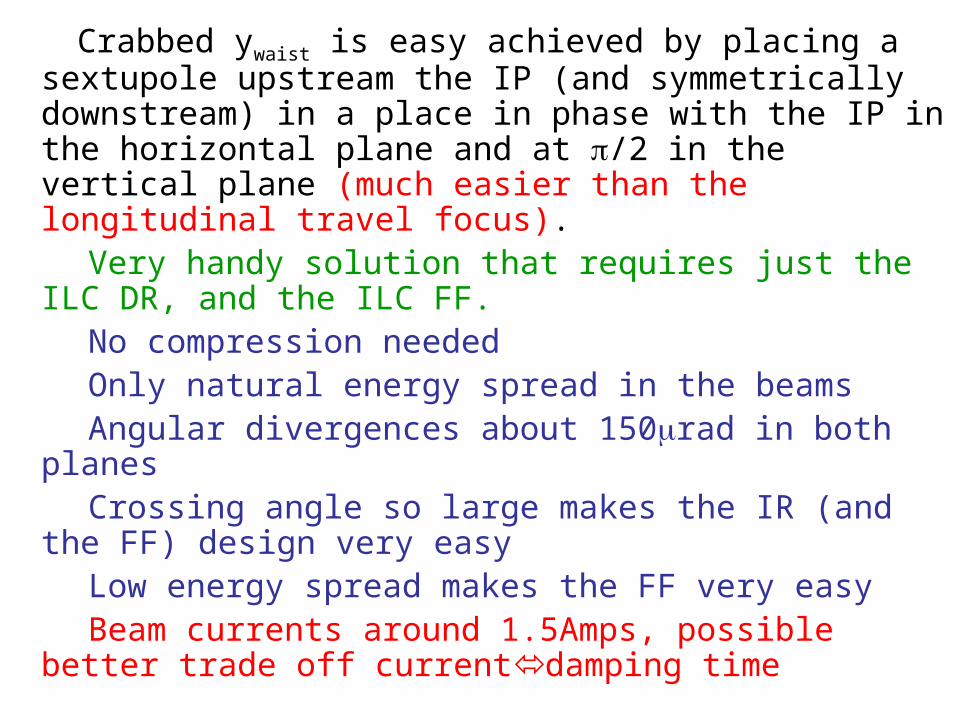
Crabbed ywaist is easy achieved by placing a sextupole upstream the IP (and symmetrically downstream) in a place in phase with the IP in the horizontal plane and at /2 in the vertical plane (much easier than the longitudinal travel focus).
Very handy solution that requires just the ILC DR, and the ILC FF.
No compression needed Only natural energy spread in the beams Angular divergences about 150rad in both planes Crossing angle so large makes the IR (and the FF)
design very easy Low energy spread makes the FF very easy Beam currents around 1.5Amps, possible better trade
off currentdamping time

Collisions with uncompressed beamsCrossing angle = 2*25mradRelative Emittance growth per collision about 1.5*10-3
(Eafter_collision/Ebefore_collision=1.0015)
Horizontal Plane Vertical Plane
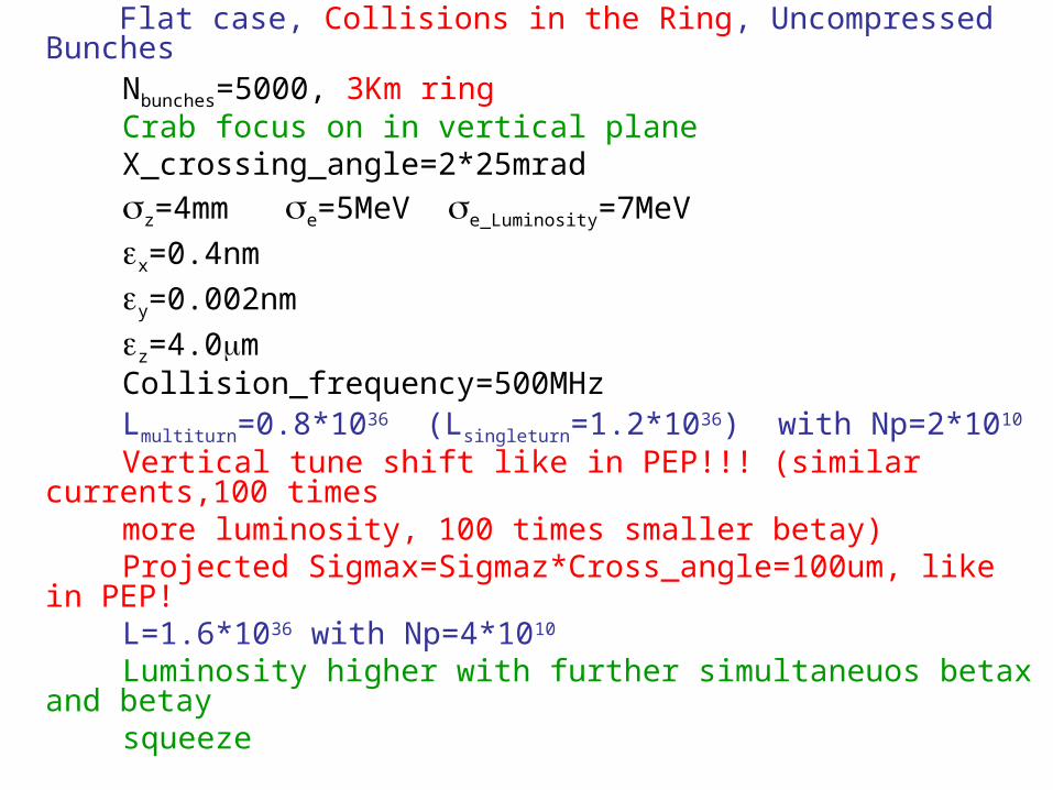
Flat case, Collisions in the Ring, Uncompressed Bunches Nbunches=5000, 3Km ring Crab focus on in vertical plane X_crossing_angle=2*25mrad
z=4mm e=5MeV e_Luminosity=7MeV
x=0.4nm
y=0.002nm
z=4.0m Collision_frequency=500MHz Lmultiturn=0.8*1036 (Lsingleturn=1.2*1036) with Np=2*1010
Vertical tune shift like in PEP!!! (similar currents,100 times more luminosity, 100 times smaller betay) Projected Sigmax=Sigmaz*Cross_angle=100um, like in PEP! L=1.6*1036 with Np=4*1010 Luminosity higher with further simultaneuos betax and betay squeeze

Multiturn simulations for uncompressed beams3Km ring, 5000 bunchesColl_freq=100Khz*5000, Lmultiturn=0.8*1036
Bunch_charge=2*1010 e=4mm, Xcrossing=2*25mrad
y0=2pm x0=400pm
IPFF FF
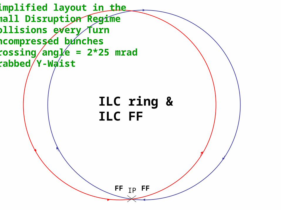
ILC ring & ILC FF
Simplified layout in the Small Disruption Regime Collisions every TurnUncompressed bunchesCrossing angle = 2*25 mradCrabbed Y-Waist

Conclusions (1):Found 2 workable parameters setsFirst set requires: - ILC damping ring, - ILC bunch compressor, - ILC Final Focus - Energy acceleration by ILC SC-cavities is not a must
anymore but for sure a factor 2 in energy gain gives us a factor 2 smaller energy spread (and a factor 2 down in beam cooling power in the ring)
- Same parameters set but with increased collision rate and reduced beam current gives more and more luminosity, with an optimal at collision rates every turn.
- Possible path is to build the machine with the capability to collide with beam-extraction every 50 turns, and then while at low bunch charge, we will have the option of increasing the bunch charge OR the collision rate up to every turn…

Conclusions (2):
Second set requires:
- ILC damping ring,
- ILC Final Focus in the ring
- Crossing angle of about 25mrad
- No compressor
- No energy acceleration

Solution with ILC DR + ILC FF seems extremely promising.
- Requires virtually no R&D- Uses all the work done for ILC- Ring and FF layouts virtually done, 3km circunference rings- 100% Synergy with ILC - IR extremely simplified- Beam stay clear about 20sigmas supposing 1cm radius beam pipe- Beam Currents around 1.5Amps- Background should be better than PEP and KEKB- Possibly to operate at the tau with L=10^35- To be studied the possibility to run down to the phi- Total cost about half of the ILC e+ DRs (2 e+ 6km rings in ILC)- Power around 40MW, still to be further optimized (goal 25MW)- Possible to reuse PEP RF system, power supplies, Vacuum pumps,
etc., further reducing the overall cost- Needs the standard injector system, probably a C-band 7GeV linac
like in KEKB upgrade (already designed) (around 100ME)
Conclusions (3)

Conclusions (4)
• Possible fall back on the existing factories
• The crabbed waist seems to be beneficial also for the current factories
• Potential to simultaneously boost the performances of the existing machines and do SuperB R&D

Action items (to be extended)
- Freeze one or two parameter sets - Define a layout - Assign working groups for the different subsystems - Define the sinergy with ILC, R&D, lattice designs, etc… - Evaluate the possibility to reuse Pep hardware. - Make a cost and power consuption estimate and
optimization - Make a time schedule - Define the international collaborations