Embed Size (px)
Citation preview

Status Report – SEALER-UK (LeadCold)
Sweden/UK DATE (2019/12/11) This reactor design is a new concept with a projected earliest commercial
deployment time of 2030.
INTRODUCTION
Development Milestones
2019 Concept design completed
2020 Engineering design complete
2021 Start of licensing procedure for demonstration unit
2024 Start of construction of demonstration unit
2026 Demonstration unit in operation
2027 Start construction of reactor factory
2030 Commercial operation of first multi-unit site
Design organization or vendor company (e-mail contact): LeadCold ([email protected])
Links to designer/vendor homepage: www.leadcold.com
Detailed Design Description: N/A
Most Recent Licensing Application Support Document: N/A
Indicate which booklet(s): [ ] Large WCR [ X ] SMR [ X ] FR
SEALER-UK is a 55 MWe lead-cooled reactor using 12 percent enriched uranium nitride
fuel. The purpose of the design is to produce base-load power on the UK grid. The reactor is
designed to permit automated manufacture in a factory, with an intended lead-time from
order to operation of 24 months. In a reference configuration of four units, a SEALER-UK
power plant may produce 220 MW of electricity at an estimated cost of £50/MWh. A single
fuel load will last 22.5 full power years, corresponding to 25 calendar years of operation.
The integrity of steel surfaces exposed to liquid lead is ensured by use of alumina forming
steels developed by LeadCold Engineers, containing 3-6 wt% aluminium. These steels are
applied either as weld overlay, as a surface alloy, or as bulk material, depending on the
radiation damage dose tolerance and mechanical strength required for a particular
component.
Passive safety of the reactor is ensured by removal of decay heat from the core by natural
convection of the lead coolant. Transport of the decay heat from the primary system is
accomplished by dip-coolers, or ultimately by radiation from the primary vessel to a
reservoir of water surrounding the guard vessel. In the event of a core disruptive accident,
volatile fission products are retained in the lead coolant and no evacuation of persons
residing at the site boundary will be required.
.

CAD representation of SEALER-UK

Table 1: ARIS Category Fields (see also Spreadsheet “Categories”) for Booklet
ARIS Category Input Select from
Current/Intended Purpose Commercial -
Electric
Commercial – Electric/Non-electric,
Prototype/FOAK, Demonstration,
Experimental
Main Intended Application
(once commercial)
Baseload Baseload, Dispatchable, Off-
grid/Remote, Mobile/Propulsion,
Non-electric (specify)
Reference Location Below-Ground On Coast, Inland, Below-Ground,
Floating-Fixed, Marine-Mobile,
Submerged-Fixed (Other-specify)
Reference Site Design
(reactor units per site)
Multiple Unit (4
units)
Single Unit, Dual Unit, Multiple Unit
(# units)
Reactor Core Size (1 core) Small (140 MWth) Small (<1000 MWth),
Medium (1000-3000 MWth),
Large (>3000 MWth)
Reactor Type LFR PWR, BWR, HWR, SCWR, GCR,
GFR, SFR, LFR, MSR, ADS
Core Coolant Pb H2O, D2O, He, CO2, Na, Pb, PbBi,
Molten Salts, (Other-specify)
Neutron Moderator None H2O, D2O, Graphite, None, (Other-
specify)
NSSS Layout Pool-type Loop-type (# loops), Direct-cycle,
Semi-integral, Integral, Pool-type
Primary Circulation
Forced (10 pumps) Forced (# pumps), Natural
Thermodynamic Cycle
Rankine Rankine, Brayton, Combined-Cycle
(direct/indirect)
Secondary Side Fluid H2O H2O, He, CO2, Na, Pb, PbBi, Molten
Salts, (Other-specify)
Fuel Form Fuel Bundle Fuel Assembly/Bundle, Coated
Sphere, Plate, Prismatic, Contained
Liquid, Liquid Fuel/Coolant
Fuel Lattice Shape Hexagonal Square, Hexagonal, Triangular,
Cylindrical, Spherical, Other, n/a
Rods/Pins per Fuel
Assembly/Bundle
271 #, n/a
Fuel Material Type Nitride Oxide, Nitride, Carbide, Metal,
Molten Salt, (Other-specify)
Design Status Conceptual Conceptual, Detailed,
Final (with secure suppliers)
Licensing Status N/A DCR, GDR, PSAR, FSAR, Design
Licensed (in Country), Under
Construction (# units), In Operation
(# units)

Table 2: ARIS Parameter Fields (see also Spreadsheet “Data”) for Booklet
ARIS Parameter Value Units or Examples
Plant Infrastructure
Design Life
25
years
Lifetime Capacity Factor
96%
%, defined as Lifetime MWe-yrs
delivered / (MWe capacity * Design
Life), incl. outages
Major Planned Outages 14 days every 12
months (prev. maint)
# days every # months (specify purpose,
including refuelling)
Operation / Maintenance
Human Resources
60 staff in operation
per unit
# Staff in Operation / Maintenance Crew
during Normal Operation
Reference Site Design
4 units
n Units/Modules
Capacity to Electric Grid
4 x 55 MWe
MWe (net to grid)
Non-electric Capacity N/A
e.g. MWth heat at x ºC, m3/day
desalinated water, kg/day hydrogen, etc.
In-House Plant Consumption
2-3 MWe
MWe
Plant Footprint
80 x 60 m2
m2 (rectangular building envelope)
Site Footprint
150 x 200 m2
m2 (fenced area)
Emergency Planning Zone
1 km
km (radius)
Releases during Normal
Operation N/A
TBq/yr (Noble Gases / Tritium Gas /
Liquids)
Load Following Range
and Speed
N/A x – 100%,
% per minute
Seismic Design (SSE)
N/A
g (Safe-Shutdown Earthquake)
NSSS Operating Pressure
(primary/secondary) 0.1 MPa/16.5 MPa
MPa(abs), i.e. MPa(g)+0.1, at
core/secondary outlets
Primary Coolant Inventory
(incl. pressurizer) 700 000
kg
Nominal Coolant Flow Rate
(primary/secondary) 7400 kg/s / 76 kg/s
kg/s
Core Inlet / Outlet Coolant
Temperature 420ºC /550ºC
ºC / ºC
Available Temperature as
Process Heat Source
ºC
NSSS Largest Component Guard Vessel
e.g. RPV (empty), SG, Core Module
(empty/fuelled), etc.
- dimensions 6.0 m / 4.8 m /
50000 kg
m (length) / m (diameter) / kg (transport
weight)
Reactor Vessel Material SS316L with weld
overlay
e.g. SS304, SS316, SA508, 800H,
Hastelloy N
Steam Generator Design Spiral tube stack
e.g. Vertical/Horizontal, U-Tube/
Straight/Helical, cross/counter flow

ARIS Parameter Value Units or Examples
Secondary Coolant Inventory
kg
Pressurizer Design
e.g. separate vessel, integral, steam or gas
pressurized, etc.
Pressurizer Volume
/
m3 / m3 (total / liquid)
Containment Type and Total
Volume /
Dry (single/double), Dry/Wet Well,
Inerted, etc. / m3
Spent Fuel Pool Capacity and
Total Volume N/A
years of full-power operation / m3
Fuel/Core
Single Core Thermal Power
140 MWth
MWth
Refuelling Cycle
None
months or “continuous”
Fuel Material
UN
e.g. UO2, MOX, UF4, UCO
Enrichment (avg./max.)
11.8%/11.8%
%
Average Neutron Energy
eV
Fuel Cladding Material
15-15Ti
e.g. Zr-4, SS, TRISO, E-110, none
Number of Fuel “Units”
85 SA
specify as Assembly, Bundle, Plate,
Sphere, or n/a
Weight of one Fuel Unit
220 kg
kg
Total Fissile Loading (initial) 2300 kg U-235
(nitride)
kg fissile material (specify isotopic and
chemical composition)
% of fuel outside core during
normal operation N/A
applicable to online refuelling and molten
salt reactors
Fraction of fresh-fuel fissile
material used up at discharge 6%
%
Core Discharge Burnup
60 MWd/kg U
MWd/kgHM (heavy metal, eg U, Pu, Th)
Pin Burnup (max.)
120 MWd/kg U
MWd/kgHM
Breeding Ratio 1.0
Fraction of fissile material bred in-situ
over one fuel cycle or at equilibrium core
Reprocessing
None
e.g. None, Batch, Continuous (FP
polishing/actinide removal), etc.
Main Reactivity Control Rods
e.g. Rods, Boron Solution, Fuel Load,
Temperature, Flow Rate, Reflectors
Solid Burnable Absorber
N/A
e.g. Gd2O3,
Core Volume (active)
4.0 m3
m3 (used to calculate power density)
Fast Neutron Flux at Core
Pressure Boundary N/A
N/m2-s
Max. Fast Neutron Flux
4.5 x 10¹⁴ n/m2/s
N/m2-s

ARIS Parameter Value Units or Examples
Safety Systems
Number of Safety Trains Active / Passive
% capacity of each train to fulfil safety
function
- reactor shutdown
0/1 -/100%
- core injection
1/0 100%/
- decay heat removal
1/1 100%/100%
- containment isolation and
cooling N/A /
- emergency AC supply
(e.g. diesels) None /
DC Power Capacity
(e.g. batteries) 72 h
hours
Events in which Immediate
Operator Action is required None
e.g. any internal/external initiating
events, none
Limiting (shortest) Subsequent
Operator Action Time Indefinite
hours (that are assumed when following
EOPs)
Severe Accident Core
Provisions Pb coolant
e.g. no core melt, IVMR, Core Catcher,
Core Dump Tank, MCCI
Core Damage Frequency
(CDF) N/A
x / reactor-year (based on reference site
and location)
Severe Accident Containment
Provisions Pb coolant filter
e.g. H2 ignitors, PARs, filtered venting,
etc.
Large Release Frequency
(LRF) N/A
x / reactor-year (based on reference site
and location)
Overall Build Project Costs Estimate or Range
(excluding Licensing, based on the Reference Design Site and Location)
Construction Time
(nth of a kind) 24 months
months from first concrete to criticality
Design, Project Mgmt. and
Procurement Effort
person-years (PY) [DP&P]
Construction and
Commissioning Effort
PY [C&C]
Material and Equipment
Overnight Capital Cost
Million US$(2015) [M&E],
if built in USA
Cost Breakdown %[C&C] / %[M&E]
- Site Development before first
concrete /
(e.g. 25 / 10 )
( 30 / 40 )
( 20 / 25 )
( 20 / 10 )
( 5 / 15 )
( -----------)
(to add up to 100 / 100)
- Nuclear Island (NSSS)
/
- Conventional Island (Turbine
and Cooling) /
- Balance of Plant (BOP)
/
- Commissioning and First
Fuel Loading /
Factory / On-Site
split in [C&C] effort /
% / % of total [C&C] effort in PY
(e.g. 60 / 40 )

1. Plant Layout, Site Environment and Grid Integration
SUMMARY FOR BOOKLET
1.1. Site Requirements during Construction
Figure 1.1 shows the layout of a 4x55MWe SEALER-UK plant, with its reactor units located
under ground and where two units share a control room. The foot-print of the site is 150 x 200
m, and that of each reactor building 25 x 25 m.
Figure 1.1: Conceptual layout of a 4x55 MWe SEALER-UK plant with its reactor units
located underground.
1.2. Site Considerations during Operation
o Not provided
1.3. Grid Integration
o Not provided
In the 4x55MWe SEALER-UK plant, all reactor units are located underground and two
units share a common control room. The foot-print of the site is 150 x 200 m, and that of
each reactor building 25 x 25 m.
2. Technical NSSS/Power Conversion System Design
SUMMARY FOR BOOKLET
2.1. Primary Circuit
Figure 2.1 shows a CAD representation of the primary system of SEALER-UK, including the
location of fuel assemblies, pumps and steam generators.
Figure 2.1: CAD representation of the primary system of SEALER-UK
Figure 2.2 shows the principles for decay heat removal by means of dip-coolers and a guard
vessel immersed into an emergency cooling water pool.

Figure 2.2: General layout of the Decay Heat Removal systems of SEALER-UK.
2.2. Reactor Core and Fuel
The reactor core consists of 85 fuel assemblies, six control assemblies, six shut-down
assemblies and 72 reflector assemblies. A core map is displayed in Figure 2.3.
Figure 2.3: Core map for SEALER-UK.
Fuel assembly Reflector
assembly
Control
assemblyShutdown
assembly

Dimensioning and characteristics of fuel rods and fuel assemblies is provided in the table
below.
Item Value
Fuel pellet composition UN 235U enrichment 11.8% 15N enrichment 99.5%
Pellet porosity 10.0%
Pellet density 12.9 g/cm3
Pellet diameter 8.12 mm
Fuel column active height 1305 mm
Lower SS316 end cap height 25 mm
Lower B4C shield height 100 mm
Lower ZrN reflector height 100 mm
Upper ZrN reflector height 10 mm
Upper gas plenum height 500 mm
Upper SS316 end cap height 20 mm
Fuel cladding material 15-15Ti
Fuel cladding surface alloy Fe-10Cr-6Al-RE
Fuel cladding inner/outer diameter 8.56/9.60 mm
Fuel rod pitch 11.3 mm
Hex-can material Fe-10Cr-4Al-RE
Hex-can inner/outer flat-to-flat 188.5/194.5 mm
Hex-can pitch 198.5 mm
The fuel burn-up is limited by the peak damage dose (160 dpa) to the fuel cladding. This
results in a peak peak/average burn/up of 110/60 GWd/ton respectively.
12% enriched UF6 may be provided by TENEX or possibly in the future by URENCO.
LeadCold intends to set up a factory for synthesis of UN powder using ammonolysis of UF6.
High density uranium nitride fuel pellets will be manufactured using spark plasma sintering.
2.3.Fuel Handling
No fuel handling is foreseen during the operational life of the plant.
2.4.Reactor Protection
The reactivity swing of the SEALER-UK core is estimated at 540 pcm during 22.5 full power
years (60 GWd/t average burn-up), where peak reactivity occurs at middle-of-life. This value
includes reactivity decrements due to axial swelling of the fuel. The reactivity swing is
compensated for by insertion and consequent withdrawal of six natural B4C control-rod
assemblies.
Passive reactor shut-down is achieved by insertion of six shut-down assemblies containing
CerMet composite W-(W,Re)10B2 pellets, having a density higher than lead. The reactivity
worth of these assemblies exceed 1000 pcm.
The fission gas plenum of the control rods is dimensioned so that the fuel rod cladding shall
not undergo creep rupture failure during any transient where the cladding temperature
remains below 973 K, taking into account full fission gas release into the plenum.

Volatile fission products are retained in the coolant by formation of lead iodide and Pb-Cs
Zintl compounds. The retention factor is calculated to be in excess of 99.99% at a primary
system coolant temperature of 973 K.
2.5. Secondary Side
A simplified description of the secondary side is provided in Figure 2.4. The super-heated
steam from the steam generators is expanded through the turbine, producing mechanical
energy, which is converted to electrical energy by a generator. The generator is connected to
the utility grid via a step-up transformer. Turbine exhaust is condensed in the condenser, and
the waste heat is rejected to the environment by the condenser cooling system. Several turbine
extractions are used for feedwater pre-heating to optimise the efficiency of the cycle. Further
efficiency improvements can be obtained by considering turbines supporting re-heat. In such
approach, the temperature of the exhaust steam from the high pressure sections of the turbine
is increased by re-heating, before the steam is supplied to the low pressure sections.
The condensate is pumped from the condenser through the purification system and the low
pressure pre-heaters to the feed-water tank. The low pressure pre-heaters utilise extraction
steam from the turbine. The feed-water tank acts as the on-line feed-water storage, pre-heater
and deaerator. The feed-water tank is heated by extraction steam from the turbine and the
drains from the high pressure pre-heaters. High pressure feed-water pumps take the feed-
water from the feed-water tank and supply it back to the steam generators through a
combination of high pressure pre-heaters. The high pressure pre-heaters utilise extraction
steam from the turbine, except for the last pre-heater which utilises live steam from the steam
line. Live steam is required to provide the desired feed-water temperature control.
Figure 2.4: Drawing of power conversion system
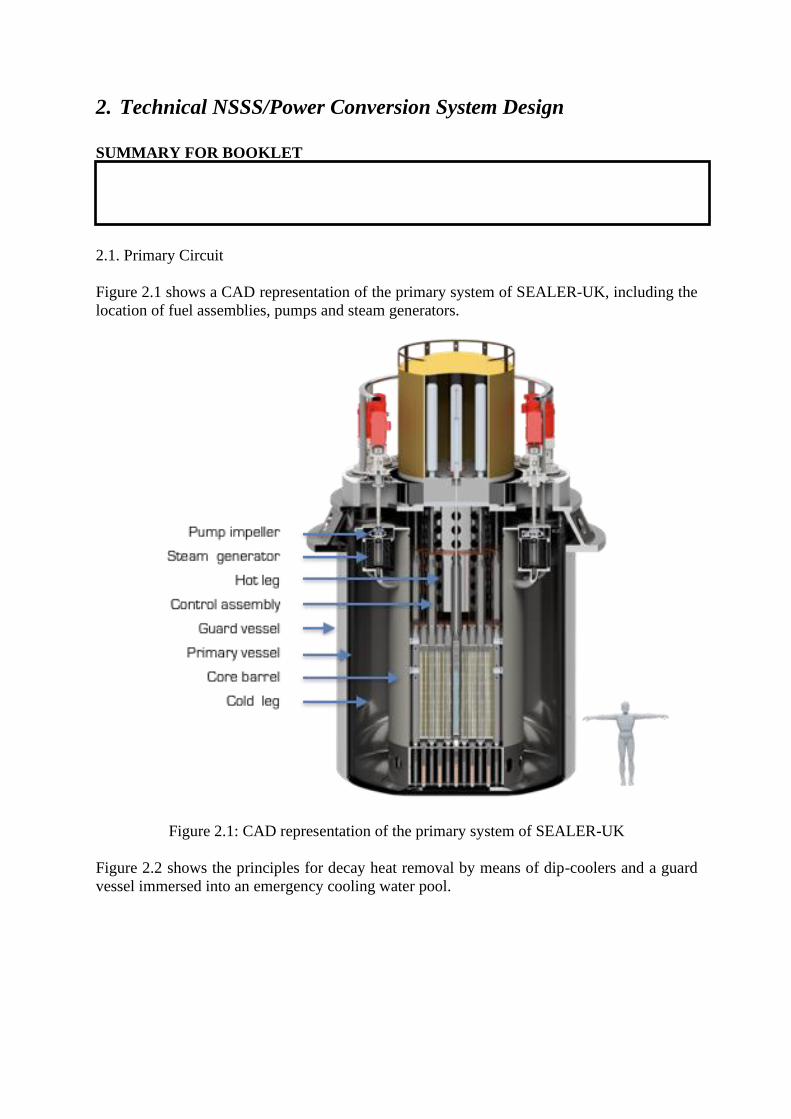
The main parameters of the power conversion system are summarized in the table below
together with the assumptions applied in the calculations.
Item Value
Steam generator power 14 MW
No of steam generators 10
Steam pressure at steam generator outlet 15 MPa
Steam temperature at steam generator outlet 530 C
Feed water temperature at steam generator inlet 335 C
Total steam mass flow rate 76 kg/s
Condenser temperature 30 C
Feed water tank pressure 8 bar
Turbine thermal power 60 MW
Generator output 58 MW
Cycle conversion efficiency > 40%

3. Technology Maturity/Readiness
SUMMARY FOR BOOKLET
3.1. Deployed Reactors
o N/A
3.2. Reactors under Licensing Review
o N/A
3.3. Reactors in the Design Stage
o In 2019, the SEALER-UK design is at TRL 3-4.
o Component testing and qualification has to be done for pumps and steam generators.
Irradiation tests of alumina forming steels and spark plasma sintered UN fuel is to be
conducted. An integral test of an electrically heated scale model is foreseen, bringing
the design to TRL 7.
o The design is simplified by eliminating fuel reloading equipment, spent fuel storage
pools, and emergency diesel power generators, as well as avoiding safety
classification of the secondary system. A unique feature is the use of alumina forming
steels for corrosion and erosion protection.
o The design and construction of the SEALER-UK reactor will comply with the ISO-
19443 nuclear standard.
o Preventive maintenance is foreseen to include an annual replacement of pump/steam
generator packages
o Main completed and remaining R&D and licensing stages and their duration
o The design authority of SEALER-UK is LeadCold. Supporting R&D has been carried
out by KTH, NRG, CRA, SUPSI, Manchester University, McMaster University and
engineering studies were conducted by Safetech, Inprotec, Promation Nuclear and
TSP Engineering.
o The SEALER-UK reactor could be licensed for construction and operation in the UK
within four years after submission of a license application.
In 2019, the SEALER-UK design is at TRL 3-4.
Component testing and qualification has to be done for pumps and steam generators.
Irradiation tests of alumina forming steels and spark plasma sintered UN fuel is to be
conducted. An integral test of an electrically heated scale model is foreseen, bringing the
design to TRL 7.

4. Safety Concept
SUMMARY FOR BOOKLET
4.1. Safety Philosophy and Implementation
o SEALER-UK is designed to manage beyond design basis accidents (initiated by
simultaneous failure of two reliable safety systems) with consequences that are less
than for conventional design basis accidents. Hence, BDBA events are treated as
DBAs in the safety analysis of LeadCold.
o Defence in-depth is provided by a series of barriers to release of fission products,
which include the uranium nitride fuel pellet, ensuring a low temperature and minimal
release of volatiles during transients, the fuel cladding, being protected from corrosion
attack by an alumina forming alloy, the lead coolant, providing chemical retention
capability up to high temperatures, the primary vessel operating under low pressure
conditions and finally a steel confinement.
o The safety classified systems operate by means of passive mechanisms, such as
insertion by gravity of shut-down rod elements containing high density tungsten
composites, insertion by gravity of water into dip-coolers providing natural
convection of the primary lead coolant, and radiation of decay heat from the primary
vessel to a guard vessel immersed into an emergency cooling water pool. The design
intent is to achieve indefinite grace time for operator intervention, with the exception
of battery power for post accident radiological monitoring.
SEALER-UK is designed to manage beyond design basis accidents (initiated by
simultaneous failure of two reliable safety systems) with consequences that are less than
for conventional design basis accidents. Hence, BDBA events are treated as DBAs in the
safety analysis of LeadCold.
Defence in-depth is provided by a series of barriers to release of fission products, which
include the uranium nitride fuel pellet, ensuring a low temperature and minimal release
of volatiles during transients, the fuel cladding, being protected from corrosion attack by
an alumina forming alloy, the lead coolant, providing chemical retention capability up to
high temperatures, the primary vessel operating under low pressure conditions and
finally a steel confinement.
The safety classified systems operate by means of passive mechanisms, such as insertion
by gravity of shut-down rod elements containing high density tungsten composites,
insertion by gravity of water into dip-coolers providing natural convection of the
primary lead coolant, and radiation of decay heat from the primary vessel to a guard
vessel immersed into an emergency cooling water pool. The design intent is to achieve
indefinite grace time for operator intervention, with the exception of battery power for
post accident radiological monitoring.
In the case of postulated fuel cladding damage, the lead coolant inventory is calculated
to retain a least 99.99% of the iodine realeased from fuel pellets, which is sufficient to
ensure meeting the radiation protection goals of the design.
Aircraft impact is mitigated by underground location of the plant.

o Radiation damage is mitigated by keeping operational temperatures above 420
degrees C, thus avoiding liquid metal embrittlement, and the peak damage dose to the
fuel cladding below permissible limits.
o The radiation protection goal is to limit the dose to persons residing outside of the site
boundary to a level ensuring that no relocation nor evacuation will be necessary.
4.2. Transient/Accident Behaviour
o SEALER-UK is designed to manage beyond design basis accidents (initiated by
simultaneous failure of two reliable safety systems) with consequences that are less
than for conventional design basis accidents. Hence, BDBA events are treated as
DBAs in the safety analysis of LeadCold. Hence, unprotected loss of flow (ULOF),
un-protected loss of heat sink (ULOHS), un-protected transient over-power (UTOP),
station blackout (SBO) and un-protected blockage (UBA) are considered as limiting
cases for DBA analysis. Loss of coolant is considered to be excluded by design.
o The safety systems that are designed to manage the above set of limiting transients are
dip-coolers, activated by opening of a valve to a water tank located above the primary
system, and an emergency cooling water pool, into which the guard vessel is
immersed. Heat transfer to the guard vessel from the primary vessel is actuated in a
completely passive manner when the temperature of the primary system increases
above the operational regime.
o The behaviour under ULOF, ULOHS and UTOP accidents has been assessed using
SAS4A-SASSYS-1 and LeadCold’s in-house code BELLA. Preliminary findings
indicate that margins to failure of cladding and vessel barrirers are maintained during
the entire course of the transient.
o In the case of postulated fuel cladding damage, the lead coolant inventory is
calculated to retain a least 99.99% of the iodine realeased from fuel pellets, which is
sufficient to ensure meeting the radiation protection goals of the design.
o Aircraft impact is mitigated by underground location of the plant. Analysis of seismic,
fire and flooding events remain to be conducted, which is also the case for a
probabilistic safety analysis.

5. Fuel and Fuel Cycle
SUMMARY FOR BOOKLET (optional)
5.1. Fuel Cycle Options
o SEALER-UK operates on a once-through fuel cycle. The spent fuel will be left in the
primary reactor vessel, which once the lead coolant is frozen, will serve as a final
disposal package.
o In case a recycling option for used uranium nitride fuel will become available and cost
competitive with respect to enrichment of natural uranium, the spent fuel of SEALER-
UK may be reprocessed and enriched uranium, plutonium and possibly minor
actinides may be recovered and refabricated into nuclear fuel for future SEALER
plants that are designed to operate on such fuel.
5.2. Resource Use Optimization
o Not provided
5.3. Unique Fuel/Fuel Cycle Design Features (if any)
SEALER-UK operates on a once-through fuel cycle. The spent fuel will be left in the
primary reactor vessel, which once the lead coolant is frozen, will serve as a final disposal
package.

6. Safeguards and Physical Security
SUMMARY FOR BOOKLET (optional)
6.1. Safeguards
o The inventory of the fuel inside the sealed core barrel may be assessed using
measurements of reactivity and neutron activity of irradiated fuel.
6.2. Security
o The SEALER-UK reactor units are located underground, mitigating the impact of
airplane crashes and delaying access to vital areas. The core barrel will be sealed,
considerably delaying any access to the fuel assemblies.
6.3. Unique Safeguards and/or Security Features (if any)
The SEALER-UK reactor units are located underground, mitigating the impact of airplane
crashes and delaying access to vital areas. The core barrel will be sealed, considerably
delaying any access to the fuel assemblies.

7. Project Delivery and Economics
SUMMARY FOR BOOKLET (optional)
7.1. Project Preparation and Negotiation
Not provided
7.2. Construction and Commissioning
o The overnight capital cost of a 4x55 MWe SEALER-UK plant is estimated at GBP
400 million.
o This figure is based on the assumption that the primary system is manufactured in a
factory where automated procedures are applied. The time from ordering of the plant
to operation is planned to be 24 months.
o
7.3. Operation and Maintenance
o The lifetime LCOE for a 4x55 MWe SEALER-UK plant is estimated at GBP
50/MWh, assuming an interest rate of 6%.
o This rate assumes a design life of 25 years, and a capacity factor of 90%. The former
is limited by radiation damage dose to the fuel cladding (there is no fuel reload
foreseen during the life of the reactor. The latter is arrived at by allocation of an
annual maintenance and quality inspection period of 35 days.
o The O&M cost is estimated to be GBP 17/MWh, including fees for spent fuel, waste
management and decommissioning.
o An equivalent fuel cost of GBP 12/MWh is estimated. The single fuel load is paid for
up-front and may alternatively be included in the capital cost of the plant at an
expense of GBP 170 million for a 4x55 MWe plant.
o No storage costs for fuel during operation are foreseen, as all fuel is located in the
primary vessel.
o Plant decommissioning costs are included in the spent fuel and decommissioning fee,
which is part of the O&M cost of GBP 17/MWh.
The overnight capital cost of a 4x55 MWe SEALER-UK plant is estimated at GBP 400
million.
This figure is based on the assumption that the primary system is manufactured in a factory
where automated procedures are applied. The time from ordering of the plant to operation is
planned to be 24 months. The lifetime LCOE for a 4x55 MWe SEALER-UK plant is
estimated at GBP 50/MWh, assuming an interest rate of 6%.