Embed Size (px)
Citation preview

Status Report – ThorCon (Thorcon US, Inc.) USA/Indonesia 2020/06/22
This reactor design is a new concept with a projected earliest deployment time of 2025.
INTRODUCTION
Development Milestones
2015 Concept design completed
2019 Pre-licensing vendor design review in Indonesia
2019 Basic engineering design complete
2021 Start construction of Pre-fission Test Platform
2022 Testing of the Pre-fission Test Platform
2023 Construction of the demonstration power plant
2024 Begin testing of the demonstration power plant
2025 Complete testing of the demonstration power plant; obtain design certification
2026 Begin commercial construction of multiple power plants
2028 Start of commercial operation of multiple power plants
Design organization or vendor company: ThorCon US, Inc., Stevenson WA, USA
Detailed Design Description: http://ThorConPower.com/design
Most Recent Licensing Application Support Document:
• Preliminary Safety Analysis Report (PSAR), due in 2020
Indicate which booklet(s): [ ] Large WCR [ X ] SMR [ ] FR
ThorCon is a molten salt fission reactor. Unlike all current nuclear reactors, the fuel is in
liquid form, which can be moved around with a pump and passively drained. This 500 MWe
fission power plant is built in a hull by a shipyard, towed to a shallow water site, and
ballasted to the seabed.
ThorCon is a straightforward scale-up of the successful Molten Salt Reactor Experiment
(MSRE) at the Oak Ridge National Laboratory, United States. A full-scale 500 MWe
ThorCon prototype can be tested within four years, that is, by 2025. After proving the plant
safely handles multiple potential failures and hazards, commercial production can begin.
A ThorCon plant requires less of the planet’s resources than a coal plant. Assuming efficient,
evidence-based regulation, ThorCon can produce clean, reliable, CO2-free electricity at
US$0.03/kWh — cheaper than coal. The complete ThorCon plant is manufactured in 150 to
500 ton blocks in a shipyard, assembled, then towed to the deployment site. This produces
order of magnitude improvements in productivity, quality control, and build time. A single
large reactor yard can turn out twenty gigawatts of ThorCon power plants per year.

Fig 1: ThorCon 500 MWe power plant
Fig 2: Two 557 MWth power modules modules

Table 1: ARIS Category Fields (see also Spreadsheet “Categories”) for Booklet
ARIS Category Input Select from
Current/Intended Purpose Commercial –
Electric,
Prototype/FOAK
Commercial – Electric/Non-electric,
Prototype/FOAK, Demonstration,
Experimental
Main Intended Application
(once commercial)
Baseload and
Dispatchable
Baseload, Dispatchable, Off-
grid/Remote, Mobile/Propulsion,
Non-electric (specify)
Reference Location On Coast On Coast, Inland, Below-Ground,
Floating-Fixed, Marine-Mobile,
Submerged-Fixed (Other-specify)
Reference Site Design
(reactor units per site)
Dual Unit Single Unit, Dual Unit, Multiple Unit
(# units)
Reactor Core Size (1 core) Small
(2 x 557 MWth)
Small (<1000 MWth),
Medium (1000-3000 MWth),
Large (>3000 MWth)
Reactor Type MSR PWR, BWR, HWR, SCWR, GCR,
GFR, SFR, LFR, MSR, ADS
Core Coolant Molten Salts H2O, D2O, He, CO2, Na, Pb, PbBi,
Molten Salts, (Other-specify)
Neutron Moderator Graphite H2O, D2O, Graphite, None, (Other-
specify)
NSSS Layout Loop-type (4
sequential loops)
Loop-type (# loops), Direct-cycle,
Semi-integral, Integral, Pool-type
Primary Circulation
Forced (4 pumps),
1 per loop
Forced (# pumps), Natural
Thermodynamic Cycle
Rankine Rankine, Brayton, Combined-Cycle
(direct/indirect)
Secondary Side Fluid Molten Salts H2O, He, CO2, Na, Pb, PbBi, Molten
Salts, (Other-specify)
Fuel Form Liquid
Fuel/Coolant
Fuel Assembly/Bundle, Coated
Sphere, Plate, Prismatic, Contained
Liquid, Liquid Fuel/Coolant
Fuel Lattice Shape n/a Square, Hexagonal, Triangular,
Cylindrical, Spherical, Other, n/a
Rods/Pins per Fuel
Assembly/Bundle
n/a #, n/a
Fuel Material Type Molten Salt Oxide, Nitride, Carbide, Metal,
Molten Salt, (Other-specify)
Design Status Detailed Conceptual, Detailed,
Final (with secure suppliers)
Licensing Status PSAR due 2020 DCR, GDR, PSAR, FSAR, Design
Licensed (in Country), Under
Construction (# units), In Operation
(# units)

Table 2: ARIS Parameter Fields (see also Spreadsheet “Data”) for Booklet
ARIS Parameter Value Units or Examples
Plant Infrastructure
Design Life
Plant: 80, Can: 4
years
Lifetime Capacity Factor
90
%, defined as Lifetime MWe-yrs
delivered / (MWe capacity * Design
Life), incl. outages
Major Planned Outages 30 days every 48
months (Can swap)
# days every # months (specify purpose,
including refuelling)
Operation / Maintenance
Human Resources 179/30
# Staff in Operation / Maintenance Crew
during Normal Operation
Reference Site Design
2 Modules
n Units/Modules
Capacity to Electric Grid
500
MWe (net to grid)
Non-electric Capacity n/a
e.g. MWth heat at x ºC, m3/day
desalinated water, kg/day hydrogen, etc.
In-House Plant Consumption
15
MWe
Plant Footprint
67x174
m2 (rectangular building envelope)
Site Footprint
500 x 500
m2 (fenced area)
Emergency Planning Zone
0.5
km (radius)
Releases during Normal
Operation to be determined
TBq/yr (Noble Gases / Tritium Gas /
Liquids)
Load Following Range
and Speed
40 – 100
5 to 10
x – 100%,
% per minute
Seismic Design (SSE)
1.0 (under review)
g (Safe-Shutdown Earthquake)
NSSS Operating Pressure
(primary/secondary) 25.5/3.8
MPa(abs), i.e. MPa(g)+0.1, at
core/secondary outlets
Primary Coolant Inventory
(incl. pressurizer) 45,000
kg
Nominal Coolant Flow Rate
(primary/secondary) 2934/2000
kg/s
Core Inlet / Outlet Coolant
Temperature 565/704
ºC / ºC
Available Temperature as
Process Heat Source n/a
ºC
NSSS Largest Component Can
e.g. RPV (empty), SG, Core Module
(empty/fuelled), etc.
- dimensions 10.3/7.8/343,000
m (length) / m (diameter) / kg (transport
weight)
Reactor Vessel Material SS316
e.g. SS304, SS316, SA508, 800H,
Hastelloy N
Steam Generator Design Vertical
e.g. Vertical/Horizontal, U-Tube/
Straight/Helical, cross/counter flow

ARIS Parameter Value Units or Examples
Secondary Coolant Inventory
30,000
kg
Pressurizer Design n/a
e.g. separate vessel, integral, steam or gas
pressurized, etc.
Pressurizer Volume
n/a
m3 / m3 (total / liquid)
Containment Type and Total
Volume
1st 625 m3 inerted
2nd 944 m3 inerted Dry (single/double), Dry/Wet Well,
Inerted, etc. / m3
Spent Fuel Pool Capacity and
Total Volume 139/700
years of full-power operation / m3
Fuel/Core
Single Core Thermal Power
557
MWth
Refuelling Cycle
48
months or “continuous”
Fuel Material
UF4, ThF4
e.g. UO2, MOX, UF4, UCO
Enrichment (avg./max.)
~5.0/19.7
%
Average Neutron Energy
eV
Fuel Cladding Material
n/a
e.g. Zr-4, SS, TRISO, E-110, none
Number of Fuel “Units”
1
specify as Assembly, Bundle, Plate,
Sphere, or n/a
Weight of one Fuel Unit
343,000 Can + 43,000 fuelsalt
kg
Total Fissile Loading (initial) 630 kg U235 as
19.7% enriched UF4 kg fissile material (specify isotopic and
chemical composition)
% of fuel outside core during
normal operation >50%
applicable to online refuelling and molten
salt reactors
Fraction of fresh-fuel fissile
material used up at discharge 50%
%
Core Discharge Burnup
509 MWd/kgU
MWd/kgHM (heavy metal, eg U, Pu, Th)
Pin Burnup (max.)
n/a
MWd/kgHM
Breeding Ratio 0.25 from U238 0.25 from Th232
Fraction of fissile material bred in-situ
over one fuel cycle or at equilibrium core
Reprocessing
None
e.g. None, Batch, Continuous (FP
polishing/actinide removal), etc.
Main Reactivity Control Temperature, via
flow rate e.g. Rods, Boron Solution, Fuel Load,
Temperature, Flow Rate, Reflectors
Solid Burnable Absorber
None
e.g. Gd2O3,
Core Volume (active)
8.4 m3 fuelsalt,
100 m3 Ttotal m3 (used to calculate power density)
Fast Neutron Flux at Core
Pressure Boundary TBD
N/m2-s
Max. Fast Neutron Flux
TBD
N/m2-s

ARIS Parameter Value Units or Examples
Safety Systems
Number of Safety Trains Active 0 / Passive 2 @ 100%
% capacity of each train to fulfil safety
function
- reactor shutdown
0 / 3 / 100%
- core injection
none /
- decay heat removal
0 / 3 / 100%
- containment isolation and
cooling
3 levels/
3 systems /
- emergency AC supply
(e.g. diesels)
not important to
safety /
DC Power Capacity
(e.g. batteries)
not important to
safety hours
Events in which Immediate
Operator Action is required none
e.g. any internal/external initiating
events, none
Limiting (shortest) Subsequent
Operator Action Time ~3000
hours (that are assumed when following
EOPs)
Severe Accident Core
Provisions
Fuel salt drain tank
plus core catcher e.g. no core melt, IVMR, Core Catcher,
Core Dump Tank, MCCI
Core Damage Frequency
(CDF) n/a
x / reactor-year (based on reference site
and location)
Severe Accident Containment
Provisions n/a
e.g. H2 ignitors, PARs, filtered venting,
etc.
Large Release Frequency
(LRF)
LRF=0; Cs, Sr, I
remain in fuel salt x / reactor-year (based on reference site
and location)
Overall Build Project Costs Estimate or Range
(excluding Licensing, based on the Reference Design Site and Location)
Construction Time
(nth of a kind) 24 months
months from first concrete to criticality
Design, Project Mgmt. and
Procurement Effort
FOAK costs
~100 person-years person-years (PY) [DP&P]
Construction and
Commissioning Effort included below
PY [C&C]
Material and Equipment
Overnight Capital Cost
US$1,000
million/GWe, built
in shipyard
Million US$(2015) [M&E],
if built in USA
Cost Breakdown %[C&C] / %[M&E]
- Site Development before first
concrete included above
(e.g. 25 / 10 )
( 30 / 40 )
( 20 / 25 )
( 20 / 10 )
( 5 / 15 )
( -----------)
(to add up to 100 / 100)
- Nuclear Island (NSSS)
included above
- Conventional Island (Turbine
and Cooling) included above
- Balance of Plant (BOP)
/included above
- Commissioning and First
Fuel Loading
US$350 million for
8 GW-years Factory / On-Site
split in [C&C] effort 90/10
% / % of total [C&C] effort in PY
(e.g. 60 / 40 )

1. Plant Layout, Site Environment and Grid Integration
SUMMARY FOR BOOKLET
1.1. Site Requirements during Construction
The construction site for the ThorCon hull is a shipyard. The deployment site should be in
shallow water near the ocean shore or up a river or other navigable water body. Depth should
be 5-10 meters. Each ThorCon power plant is a hull 174 m long by 66 m wide, 33 meters
high. The ThorCon hull will be towed from the shipyard construction site then floated into
position and ballasted down to a prepared, sandy seabed. The ballast in the hull walls is sand,
water, or concrete. Breakwaters will be built to protect against large waves or errant ships. A
cooling water pipe will be constructed to bring in suitable cooling water from perhaps a
kilometer distant. The plant must be accessible to an ocean-going CanShip that exchanges
fuelsalt casks and reactor Cans. A connection to one electric transmission line must be
provided.
A ThorCon power plant is built into a hull by a shipyard, then towed by sea to a nearshore
location and ballasted securely to the seafloor. The sea provides for transport of the complete
power plant, the provisioning of fuel and reactor Cans, and water for steam condenser
cooling. The plant achieves a net power/thermal efficiency of 46.4% with 30°C cooling
water, compared to about 33% for a standard light water reactor, reducing capital costs and
cutting cooling water needs by 60%.
ThorCon does not rely on electric power from the grid for startup or any electricity for safety.
The plant can load-follow, handle disconnects, self-start, and also help blackstart a powerless
grid. Regular maintenance will occur at 4-year intervals, when a CanShip visits to exchange
fuel casks and Cans.
Fig 3: 2 x 500 MWe ThorCon power plants with Can and fuelsalt service ship

The land adjacent to the deployment site should be prepared with perimeter fencing, security
gates, local power, roads, and employee parking; the plant site should include the area within
approximately 500 meters of the plant.
If the site is in shallow seawater kilometers from land, undersea transmission cables may be
installed (AC or DC), and provision made for employees to be ferried to and from the site. At
distances exceeding 50-80 km, HVDC may be the most economic option.
1.2. Site Considerations during Operation
The plant steam condensers will be cooled by seawater or lake water or river water. The plant
achieves a net-power/thermal efficiency of 46.4% with 30°C cooling water, improving with
colder water. Fresh water needs are provided by plant desalination systems. A staff of 209
employees will operate the plant.
Regular maintenance will occur at 4-year intervals, when a CanShip visits to exchange fuel
casks and Cans. Specially trained crews will arrive to oversee exchanges and service the steam
turbine generator.
At end of life used fuelsalt is placed in fuelsalt casks. The casks and Cans are removed by a
CanShip. The complete hull can be de-ballasted, re-floated, and towed away.
1.3. Grid Integration
ThorCon power plants will be constructed to meet local grid transmission needs, such as 500
MWe 345 kV 3-phase delta 50 Hz. A connection to one electric transmission line must be
provided. A 250 MWe plant is available at a slightly higher cost per MWe of capacity. The
plant can increase or decrease generated power by 5-10% per minute. There is no xenon-block
delay in power level restoration. On disconnect of grid transmission line or other loss of load
the plant can continue in warm standby island mode, generating in-house power with the sentry
turbine generator, ready to resupply power to the grid quickly. The plant also has the capability
to blackstart itself and help blackstart a powerless grid.

2. Technical NSSS/Power Conversion System Design
SUMMARY FOR BOOKLET
2.1. Primary Circuit
A ThorCon plant is divided into two 250 MWe power modules or PMODs. Each module
contains two replaceable reactors in sealed Cans. The Cans sit in silos. At any one time, just
one of the Cans of each module is producing power. The other Can is in cooldown mode. Every
four years the Can that has been cooling is removed and replaced with a new Can. The used
fuelsalt is transferred to the new Can, and the Can that has been operating goes into cool down
mode.
The primary loop is in a sealed Can. Fuelsalt flows through the primary loop containing the
reactor Pot, the primary loop pump (PLP), and the primary heat exchanger (PHX). The
graphite moderator in the Pot contains channels through which fuelsalt flows up. Fuelsalt
enters/leaves the Pot at 565/704°C. Pot pressure is 3 bar gage, about the same as a garden
hose. The thermal energy output per Can is 557 MWth. The Can is a cylinder 11.6 m high
and 7.3 m in diameter, weighing about 400 tons. The Can has only one major moving part,
the primary loop pump.
ThorCon employs four flow loops for converting nuclear heat to electric power, 1) the
primary loop inside the Can, 2) the secondary salt loop, 3) a solar salt loop, and 4) a
supercritical steam loop. ThorCon is a high temperature reactor with thermal efficiency of
46.4% compared to about 33% for a standard light water reactor, reducing capital costs and
cutting cooling water needs by 60%.
The ThorCon steam loop is a standard, single reheat, super-critical steam cycle, nearly off
the shelf technology.
Fig 4: Cutaway view of two 557 MWth power modules

2.2. Reactor Core and Fuel
The Can contains the reactor, called the Pot, a primary
loop heat exchanger (PHX), and a primary loop pump
(PLP), which is a centrifugal pump. The pump takes
liquid fuelsalt — a mixture of sodium, beryllium,
uranium and thorium fluorides — from the Pot at 704C,
and pushes the fuelsalt over to the PHX at a rate of
just under 3000 kg/s. Flowing down through the PHX,
the fuelsalt transfers heat to a secondary salt, and is
cooled to 565C in the process. The fuelsalt then flows
to the bottom of the Pot, and rises through the reactor
core, which is mostly filled with a moderator made of
graphite blocks. This graphite slows the neutrons, which
fission some U-235 fuel, convert some U-238 to Pu-239
fuel, and convert some Th-232 to U-233 fuel. Fission
energy heats the fuelsalt to 704C as it rises through the
Pot. The Can has only one major moving part, the
primary loop pump.
Neutron irradiation of U-238 produces Pu-239 fissile fuel and other Pu isotopes. These
plutonium isotopes are trifluorides which remain in the molten salt solution, but the solubility
Fig 5: Pot in Can with drain tank in cold-wall silo
Can thermal output 557 MWth Can electrical ouput 258 MWe Plant efficiency 46.4% NaF-BeF2-ThF4-UF4 fuelsalt 76/12/10.2/1.8 mol pct Vapor pressure @704C ≤3 Pa Fuelsalt flow 2934 kg/s Pot inlet temp 565C Pot outlet temp 704C Loop transit time 14.6 s Pot outlet press 2.9 bara Can diameter 8.775 m Can height 10.735 m Pot diameter 7.200 m Pot height 4.575 m Can weight (no salt) 343 tons Fuelsalt weight 43 tons Fast alpha-K -2/-3 pcm/K Slow alpha-K -5/-7 pcm/K
Table 2: Reactor Can specs
is limited. After four years’ initial use in a Can the fuelsalt may be re-used for a second four
years. As the trifluorides build up and approach saturation, the fuelsalt eight-year useful life
ends. It is then stored in the vault in the hull.
Xe-135 is a fission product that absorbs neutrons so they can not fission uranium, reducing
power plant efficiency. ThorCon removes much of the Xe. The off-gas processing system uses
helium sweep gas to entrain Xe and Kr gasses, passing them slowly through the off-gas cooling
tanks within the Can where most of the Xe-135 decays to Cs-135 that is trapped there. The He,
Xe, and Kr gas mixture then flows from the Can through two hold-up tanks and a charcoal
delay line in the secondary heat exchanger cell. The gas flow continues to a cryogenic gas
processing system to separate the gasses, storing stable Xe and radioactive Kr-85 in gas bottles
and returning He for reuse as a sweep gas.
The Can life is limited by the graphite moderator in the Pot. Due to neutron irradiation the
graphite first shrinks, then swells. When it returns to its initial size its four-year useful life ends.
The fuelsalt must be removed and the Can removed and sent to the Can recycling facility.
2.3. Fuel Handling
ThorCon fuel is dissolved in molten salt. Fuelsalt is normally circulated through the primary
loop with the PLP. Fuelsalt is removed from the Pot through the freeze valves to the Fuelsalt
Drain Tank (FDT) by gravity. The FDT is composed of 32 high-temperature tolerant cylinders
cooled by heat radiation to the cold-wall. Fuelsalt is moved between tanks using pumps
powered by pulsating inert cover gas pressure.
2.4. Reactor Protection
Directly below the Can is the Fuelsalt Drain Tank (FDT), shown in light green in Fig 5. At the
bottom of the Pot are four freeze valves shown in gray. Each freeze valve is an insulated low
point in the drain line from the Pot. During normal operations each valve is cooled by a flow
of helium which freezes the fuelsalt in the valve creating a plug. The helium flow is controlled
by a thermal switch which opens passively if the temperature at the top of the loop exceeds
750C. When the helium flow stops, the plug thaws and the fuelsalt drains to the FDT, so this
drain is totally passive. Fission cannot take place in the drain tank since it has no moderator.
A critically important feature of ThorCon is the silo cooling wall or cold-wall. The cold-wall
is made up of two concentric steel cylinders, shown in blue in Fig 5. The annulus between these
two cylinders is filled with water. The top of this annulus is connected to a condenser in the
decay heat pond located at the forward end of the hull. The Can, in red in Fig 5, is cooled by
thermal radiation to the cold-wall. This heat converts a portion of the water in the wall annulus
to steam. This steam/water mixture rises by natural circulation to the condenser. The outlet of
the condenser is connected to the flooded basement where the Can silos are located. Openings
in the bottom of the outer cold-wall allow the basement water into the bottom of the cold-wall
annulus.
In this process, some of the water in the pond is evaporated and replaced by the desalination
plant. Cooling towers keep the pond close to wet bulb temperature.

Fig 6: Cold-wall fed by surrounding water; backup basement water beneath secondary heat exchanger and steam generator.
Fig 7: ThorCon’s four loops; feed heaters not shown.

The cold-wall also cools the Fuelsalt Drain Tank (FDT). The drain tank is divided into a circle
of 32 cylinders. This arrangement provides sufficient radiating area to keep the peak FDT
temperature after a drain within the limits of the tank material. This cooling process is totally
passive, requiring no operator intervention nor motive power.
1. The cold-wall keeps the Can interior below 350C during normal operation and keeps the Can
and FDT from over-heating after a drain. The fact that the cold-wall is always operating is an
important safety feature. If a problem develops in the cooling wall loop, it is expected to be
detected before a serious event occurs.
2. Inert gas in the annulus between the cold-wall and Can captures tritium that may permeate
the Can or FDT. A getter system removes the tritium from the inert gas.
3. The cold-wall cools more rapidly as the Can/FDT tank heats up, but more slowly as the
Can/drain tank cool down, which is the desired behavior to handle emergencies.
4. The cold-wall inner shell and the Can form two barriers between the fuelsalt and the cold-
wall water, even if the primary loop is breached.
5. The cold-wall passively performs these functions without any penetrations into the Can or
the fuelsalt drain tank.
2.5. Secondary Side
Power conversion
ThorCon employs four loops for converting nuclear heat to electric power:
1. The primary loop inside the Can
2. The secondary salt loop
3. A solar salt loop
4. A supercritical steam loop
Salts piped through heat exchangers converts Pot heat to steam. The secondary salt is a mixture
of sodium and beryllium fluoride containing no uranium or thorium. Hot secondary salt,
depicted in green in Fig 8, is pumped out of the top of the PHX to a Secondary Heat Exchanger
(SHX) where it transfers its heat to a mixture of sodium and potassium nitrate commonly called
solar salt from its use as an energy storage medium in solar plants. The solar salt, shown in
pink, in turn transfers its heat to a supercritical steam loop, shown in red and orange. The solar
salt loop captures any tritium that has made it to the secondary loop, and ensures that a rupture
in the steam generator does not release harmful chemicals. Such a postulated rupture harmlessly
vents to the Steam Generating Cell via a standpipe.
ThorCon is a high temperature reactor, with a thermal efficiency of 46.4% allowing the plant
to use the same supercritical steam cycle as a modern coal plant.
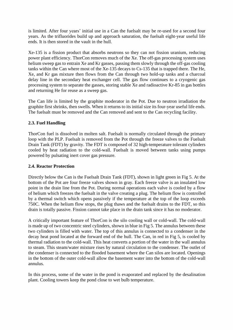
Turbine-generator system
The ThorCon steam loop is a standard, single reheat, super-critical steam cycle, essentially the
same as that currently used by coal power plants with the boiler replaced by a pollution-free
steam generator. The turbine generator and auxiliaries required to implement this power
conversion loop are not only existing technology but nearly off the shelf. Thanks to the solar
salt loop, no special high pressure feedwater preheater is required. The turbine is fitted with
100% cascade by-pass. A loss of load does not require a trip of the reactor.
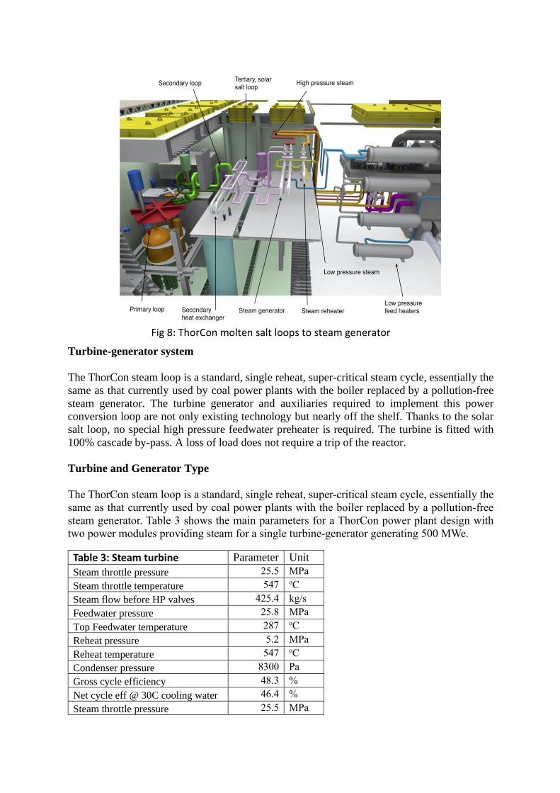
Turbine and Generator Type
The ThorCon steam loop is a standard, single reheat, super-critical steam cycle, essentially the
same as that currently used by coal power plants with the boiler replaced by a pollution-free
steam generator. Table 3 shows the main parameters for a ThorCon power plant design with
two power modules providing steam for a single turbine-generator generating 500 MWe.
Table 3: Steam turbine Parameter Unit
Steam throttle pressure 25.5 MPa
Steam throttle temperature 547 oC
Steam flow before HP valves 425.4 kg/s
Feedwater pressure 25.8 MPa
Top Feedwater temperature 287 oC
Reheat pressure 5.2 MPa
Reheat temperature 547 oC
Condenser pressure 8300 Pa
Gross cycle efficiency 48.3 %
Net cycle eff @ 30C cooling water 46.4 %
Steam throttle pressure 25.5 MPa
Fig 8: ThorCon molten salt loops to steam generator

2.6.Containment/Confinement
ThorCon has the following three gas-tight barriers between the fuelsalt and the environment:
1. The first barrier is the Can and drain tank. The Can contains the reactor Pot, the primary
loop, and the primary heat exchanger; these normally hold the circulating radioactive
fuelsalt. The fuelsalt can drain to the drain tank connected to the Can.
2. The second barrier is the silo cold-wall, in which the Can and drain tank are suspended.
3. The third barrier is the hull.
The radiation-shielded working deck above the power modules is accessible by the crew in
normal operations. Shielding not shown in Fig 11 includes a borated water neutron shield tank.
Fig 9: Steam turbine-generator layout

Recap of ThorCon’s Implementation of Control/Cool/Contain
Control
ThorCon combines a negative fuelsalt temperature coefficient of reactivity with a massive
margin between the operating temperature of 700C and the fuelsalt’s boiling temperature
(1430C). In any event that raises the temperature of the salt much above operating level,
ThorCon will passively shut itself down. There is no need for any operator intervention.
Fig 10: Two of the three radiation barriers
Fig 11: Third barrier is the hull.

Cool
1. In the event of a loss of heat sink or any upset that raises the primary loop temperature above
750C, the freeze valves will automatically open due to the increased temperature and the
fuelsalt will drain to the Fuelsalt Drain Tank, where the cold-wall will passively handle the
decay heat. There are no valves that must be realigned by either system or operator control.
There is no need for any operator intervention at any time.
2. Primary heat removal is the normal heat transport path. If that is unavailable (for example in
a station blackout) then the Pond provides 145 days of evaporative cooling, after which air
cooling of the pond condenser will extend the grace period to be infinite. In the event the
condenser to cold-wall cooling loop is also unavailable then the basement water will provide
cooling for 269 days. The steam produced in the basement water will be quenched in the hull
ballast tanks. Even if this steam were contaminated with radioactive material, which would
require a breach of both the Can and the cold-wall, there will be no release of radioactive
material to the environment. There is no need for any operator intervention for the draining to
the FDT and fuelsalt cooling.
Contain
ThorCon has three gas tight barriers between the fuelsalt and the atmosphere. The outer barrier
is a 3 m thick steel and concrete sandwich. This double sided structure can withstand a
perpendicular strike from a large commercial aircraft.
The ThorCon reactor operates at near-ambient pressure. In the event of a primary loop rupture,
there is almost no dispersal energy and no phase change. The spilled fuel merely flows to the
drain tank where it is passively cooled.
The most troublesome fission products, including I-131, Sr-90, and Cs-137, are chemically
bound to the salt. They will end up in the drain tank as well. Even if all three barriers are
somehow breached, almost all these salt seekers will not disperse. In effect, ThorCon has a
forth barrier to dispersion.
2.7. Electrical, I&C and Human Interface
Safety related electrical systems
ThorCon has no safety related electrical systems because the reactor does not depend on electric
power for safety. The plant supplies its own house power, so a grid interruption does not cause
a significant deviation from normal plant control systems. The plant passively shuts down on
its own if all power is removed from all circuits including all batteries and generators instantly
failing.
The main turbine generator provides 21 to 26 kV three-phase power. A 25,000 amp circuit
breaker connects to three single phase transformers that raise the voltage to 420 kV. Gas
insulated switchgear connects the power to overhead, air-insulated lines connecting to the
power grid.
A 15 MVA 3 phase auxiliary transformer steps 21-26 kV power down to 6 kV used by the main
in-house loads. The auxiliary transformer can be fed either from the main turbogenerator or
from the grid for startup. The 6 kV bus can also be fed by the sentry turbine generator, powered
by steam from the cold reheat line or from the auxiliary boiler during startup. Transformers
step the 6 kV voltage down to 480 volts used by smaller motors and the salt heaters such as for
the FDT. The blackstart diesels generate 480 volts.
Instrumentation and Control (I&C)
The ThorCon I&C system is not important to safety. No events related to this system can lead
to a release of radioactive materials to the environment. ThorCon safety depends only on
inherent physical principles and materials properties.
A key feature is that the connections between safety-important sensors and safety-important
actuators are direct and cannot be subverted by operators. There are no safety systems that can
be disabled by a misguided operator. I&C signals will be multiplexed and transmitted optically
to the control room via fibers.
Safety actuation is by cutting power. In a failure of power supply or wiring or sensor, cooling
of the freeze valves stops, the salt plug melts, and fuelsalt flows from the Pot to the drain tank.
Continuous power is required to avoid shutting down. If battery electric power is available,
draining is faster using electric heating of the freeze valves. This avoids creep shortening Can
economic life, but radioactivity is contained with or without power.
Important sensors are replicated and hard-wired; voting circuitry prevents inadvertent actuation
if one sensor goes bad. This reduces economic damage frequency and severity due to failing
sensors. Even if all thermoswitches and sensors simultaneously fail and erroneous voting
somehow fails to initiate a drain, the subsequent fuelsalt overheating will cause the primary
loop piping to fail and the fuelsalt will fall to the drain tank with zero release of radioactive
materials to the environment. Even such an unlikely event is an economic damage scenario
rather than a radioactive release scenario.
Control room layout
Neither the control room nor the plant operators are important to safety. The control room
operators control generated power and other generation-related parameters.
The interface between the control system and the operators will use standard computer
software, displays, keyboards, and touch pads. However, the human interface is not important
to safety.
ThorCon control room is about 7 m x 8 m. There are just three consoles and four big displays:
1. A process diagram of the fission island.
2. A process diagram of the steam loop.
3. A process diagram of the electrical system.
4. A main time series display showing trend lines of user selectable plant parameters
over a user-selectable time period.

The centerpiece of the control room is the main time series display because humans are good
at extracting information from patterns.
ThorCon safety systems are operator-independent, passive, depending on intrinsic physical
materials properties, not supplemental engineered control systems. Operators cannot override
designed-in safety systems. There are no operator actions that might lead to a release of
radioactive materials.
Also in the control room are the SCRAM switch and DRAIN switch. SCRAM releases the
shutdown rods into the reactor to stop the nuclear chain reaction. DRAIN interrupts the cold
helium supply that keeps the freeze-valve fuelsalt plugs frozen, so that fuelsalt flows from the
reactor Pot through the freeze valves to the FDT.
For backup reassurance, the operator will have access to two large red stop buttons. The
SCRAM button will physically interrupt electricity flow through the clutches that hold the
shutdown rods up. Gravity will insert the gadolinium rods into channels in the graphite core.
Any one shutdown rod has enough neutron-absorbing worth to stop the nuclear chain reaction.
The DRAIN button will physically interrupt the electricity to the cold helium supply that pumps
and refrigerates helium that keeps the fuelsalt plugs frozen in the freeze valves beneath the Pot.
As the plugs melt the fuelsalt drains from the Pot to the drain tank, ending the possibility of
criticality. If power is available this process is hastened with resistive heating of the freeze
valves.
2.8. Unique Technical Design Features (if any)
1. ThorCon will be constructed in a shipyard, then towed to the customer site.
2. The emergency planning zone will be the plant boundary.
3. The power conversion technology uses competitively sourced “off-the-shelf” supercritical
steam turbine generators.
Fig 12: Control room plan

3. Technology Maturity/Readiness
SUMMARY FOR BOOKLET
3.1. Deployed Reactors
ORNL did deploy and operate an 8 MWth molten salt reactor in the 1960s. The first deployed
ThorCon reactor will likely be the prototype to be tested in 2026 in Indonesia.
3.2. Reactors under Licensing Review
Preliminary design reviews of the ThorCon plant are underway with Bapeten, Indonesia’s
nuclear regulator.
3.3. Reactors in the Design Stage
The US Oak Ridge National Laboratory built and operated a molten salt reactor from 1966 to
1969, fuelled by U-235 and later U-233 fuel. This knowledge was carefully documented in
many reports. The MSRE was a successful experiment, producing the knowledge base that
informs the ThorCon design.
The basic design of the entire ThorCon power plant is done. The design is being detailed and
improved using information from supply chain vendors and nuclear engineers. A pre-fission
test plant will be constructed and used to confirm expected plant response to varying molten
salt flows, temperatures, pressures, and simulated perturbations and failures. These experiences
will lead to design revisions and improvements. Further fabrication design work will be done
by the engineering/procurement/construction shipyard.
The first deployed reactor will likely be the prototype under test in 2026 in Indonesia.
Preliminary reviews are underway with Bapeten, Indonesia’s nuclear regulator.
The US Oak Ridge National Laboratory built and operated a molten salt reactor from 1966
to 1969. This knowledge was carefully documented in scores of reports. The MSRE was an
extremely successful experiment, producing the knowledge base that informs the ThorCon
design.
The basic design of the ThorCon power plant is complete. It is being revised and improved
using information from supply chain vendors and nuclear engineers. A pre-fission test plant
will be constructed and used to confirm expected plant response to varying molten salt flows,
temperatures, pressures, and simulated perturbations and failures.
Potential suppliers have reviewed specs and provided cost estimates.

Potential suppliers of systems and components, including those identified in Fig 13, have
reviewed confidential design specifications. These industrial vendors have provided technical
advice and cost estimates, confirming the manufacturability and economics of ThorCon power
plants.
Fig 13: Key components with identified potential suppliers

4. Safety Concept
SUMMARY FOR BOOKLET
4.1. Safety Philosophy and Implementation
ThorCon safety philosophy is totally passive, totally unavoidable shutdown and cooling, not
requiring any operator intervention. ThorCon combines a strong negative fuelsalt temperature
coefficient with a large margin between the operating temperature of 700C and the fuelsalt’s
boiling temperature (1430C). As the reactor temperature rises, ThorCon’s power output drops.
This is an intrinsic, immutable property of the physics of the ThorCon reactor. Any event that
raises the temperature 50C above normal will initiate a shutdown and drain. ThorCon will shut
itself down.
If the high temperature of the fuel persists, a thermoswitch interrupts cooling of the freeze
valves, which will thaw and drain the fuel from the primary loop to the drain tank, where the
silo cold-wall will passively handle the decay heat. There is no need for any operator
intervention at any time. Nor are there any valves that must be realigned by either system or
operator control.
The Can and drain tank radiate heat to the silo cold-wall made of two concentric steel cylinders.
Water turning to steam in the annulus between them flows up by convection to a condenser
heat exchanger in the open decay heat pond, which transfers heat to the atmosphere. The
condensed cold-wall water cycles back to the basement surrounding the silo cold-wall. Primary
heat removal is the normal heat transport path. If that is unavailable (for example in a station
blackout) then the Pond provides 145 days of evaporative cooling, after which air cooling of
ThorCon is walkaway safe, with totally passive, totally unavoidable shutdown and cooling.
ThorCon combines a negative temperature coefficient of fuelsalt reactivity with a massive
margin between the operating temperature of 700C and the fuelsalt’s boiling temperature
(1430C). As the reactor temperature rises, power output drops. In any event that raises the
temperature of the salt much above operating level, ThorCon will shut itself down by
temperature-reduced reactivity.
If high temperature persists, the freeze valves will thaw and drain the fuel from the primary
loop to the drain tank, where the silo cold-wall will passively remove the decay heat. There
is no need for any operator intervention. There are no valves that must be realigned by
system or operator control.
ThorCon has three gas-tight barriers between the fuelsalt and the environment. The hull,
which is a double barrier, is one. The Can silo and the Can itself are the other two gas-tight
structures. All these must be breached to allow a release to the environment.
Severe transient events, such as sudden loss of electric power with simultaneous failure of
all shutdown rods, have been modeled, leading only to temporary temperature excursions up
to 1000C, within the capabilities of the steel reactor Pot and fuelsalt drain tank.
ThorCon is designed to resist earthquakes up to 1.0 g and 200 m/sec aircraft impacts.

the pond condenser will extend the grace period to be infinite. In the event the condenser to
cold-wall cooling loop is also unavailable then the basement water will provide cooling for 269
days.
The cold-wall also cools the Fuelsalt Drain Tank (FDT). The drain tank is divided into a circle
of cylinders to provide sufficient radiating area to keep the peak tank temperature after a drain
within the limits of the drain tank material. This cooling process is totally passive, requiring no
operator intervention nor any outside power. The fact that the cold-wall is always operating is
an important safety feature. There are no valves to turn on. If a problem develops in the cold-
wall loop, temperature sensors will detect the problem before it evolves into a serious event.
Overheat-detecting thermoswitches interrupt current to shutdown rod clutches, allowing them
to fall, stopping fission. Other overheat thermoswitches interrupt current to the cold helium
circulator that keeps the freeze plugs frozen, letting them melt, leading to a drain. Additional
sensors and electronic systems can also initiate actions to trip the reactor and remove decay
heat, but they are supplemental, designed to improve economic performance of the plant.
For backup reassurance, the operator will have access to two large red stop buttons. The
SCRAM button will physically interrupt electricity flow through the clutches that hold the
shutdown rods up. Gravity will insert the gadolinium rods into channels in the graphite core.
Any one shutdown rod has enough neutron-absorbing worth to stop the nuclear chain reaction.
The DRAIN button will physically interrupt the electricity to the cold helium supply that pumps
and refrigerates helium that keeps the fuelsalt plugs frozen in the freeze valves beneath the Pot.
As the plugs melt, the fuelsalt drains from the Pot to the drain tank, ending the possibility of
criticality. If power is available this process is hastened with resistive heating of the freeze
valves.
Resistance to release of radioactive materials. ThorCon has three gas tight barriers between
the fuelsalt and the environment. Fig 14 is a sectional view of the hull in way of the fission
island. The structure is similar to the cargo hold section of a large tanker with a 3 meter wide
Fig 14: Hull section showing cold-wall silos containing Cans

double bottom and double sides. In addition, a 3m deep double roof is provided in way of the
fission island. The double sides and roof are filled with sand or concrete. This is an extremely
strong structure. It will not be penetrated by a Boeing 777 aircraft’s heavy engine in a
perpendicular impact at 400 knots. The hull, which is a double barrier, is only one of three gas
tight barriers between the fuel salt and the environment. The Can silo is a gas tight structure;
and the Can itself is a gas tight structure. All these must be breached to allow a release.
Even if they were, there is no internal dispersal mechanism. The ThorCon reactor operates at
near-ambient pressure. In the event of a primary loop rupture, there is little pressure energy and
no phase change. The spilled fuelsalt merely flows to the drain tank where it is passively cooled.
Moreover, the most environmentally troublesome fission products, including iodine-131,
strontium-90 and cesium-137, are chemically bound to the salt. They will end up in the drain
tank as well.
Electric systems independence. ThorCon electrical systems are not important to safety. No
failures of the AC electric grid, the main turbine-generator, the sentry turbine-generator,
transformers, DC power systems, batteries, nor diesel generators will lead to a release of
radioactive materials to the environment. Loss of electric power will drop the shutdown rods,
stopping fission. Loss of power will also stop helium cooling of the fuelsalt freeze valves,
initiating a drain to the FDT, stopping fission. Decay heat is passively removed from the Can
and the FDT by the cold-wall system.
Passive safety systems levels.
ThorCon passive safety is based on intrinsic physical changes in solids, liquids, and gasses.
Passivity means no human actions nor motive power need be implemented. Temperature
induced material expansions or contractions and fluids flowing by gravity or natural convection
implement passive safety. IAEA classifies the degree of passive safety of components from
category A to D depending on what features the system does not make use of.
1. no moving working fluid
2. no moving mechanical part
3. no signal inputs of 'intelligence'
4. no external power input or forces
categorizing systems as level
A (1+2+3+4)
B (2+3+4)
C (3+4)
D (4 only)
Fuelsalt - level A passive safety system. ThorCon uses inherent safety to ensure that no
fission-generated runaway heating occurs. The thermal coefficient of fuelsalt reactivity is
negative, so the fission chain reaction stops if the temperature rises to 800C.
Cold-wall - level B passive safety system. The cold-wall absorbs heat radiated by the Can and
the drain tank. The cold-wall is cooled by dual natural water circulation systems that transport
heat to heat exchangers at the bottom of the cooling pond, which is open to the atmosphere, the
ultimate heat sink. There are no pumps or valves in the water circuits. The water is always
circulating, even in normal operation. If the Can or drain tank radiate more heat, the water
circulates faster due to natural convection. This functionality requires no valve change nor
operator actions. The operator can do nothing to disable the cooling.

Freeze valves - level B passive safety system. Four frozen fuelsalt plugs in the piping below
the Pot are each kept frozen by pumping cold helium though an annulus surrounding piping
from the primary loop to the fuelsalt drain tank. If the fuelsalt rises to 750C a thermoswitch
opens, directly cutting power to the helium pump. In 10-12 minutes the fuelsalt plug will melt
and fuelsalt will drain out of the Pot to the drain tank in 10-12 minutes. As the level of fuelsalt
drops in the Pot containing moderating graphite the fission chain reaction stops.
Shutdown rods - level B passive safety system. If the fuelsalt rises to 750C a thermoswitch
opens, directly cutting power to the clutches keeping three gadolinium shutdown rods from
falling into their channels in the Pot. Any one shutdown rod can stop the fission chain reaction.
Basement water - level C passive safety system. Should the cooling pond run dry due to
evaporation or structural failure, the water flow through the cold-wall will not be cooled, steam
pressure in the power module will rise, bursting a blow-out diaphragm enabling basement water
to quench steam, thus cooling the Can. No operator action is required. The only part involved
is the bursting diaphragm. Alternatively, the cooling pond could be refilled with water using
the firefighting water drench system of the ThorCon plant or fireboats.
Radiation protection goals. ThorCon will comply with the radiation protection exposure
levels and radioactive material release limits established by the host nation. Certainly the
common limits of 20 mSv/year for workers and 1 mSv/year for the general public are met.
4.2. Transient/Accident Behaviour
The transient and accident behavior of ThorCon has been modeled using modern computational
hydrodynamics software by independent experts. In a postulated accident similar to that at
Fukushima, earthquake sensors initiate a fuelsalt drain and shutdown rods drop, stopping
fission and power to the grid. [For ThorCon the sentry turbine-generator powers can supply
internal plant power using decay heat or the auxiliary boiler, maintaining the primary cooling
path function.]
At Fukushima the subsequent tsunami then cut all electric power and thus decay heat removal
via the primary cooling path. In the ThorCon case, if all electric power is subsequently lost, the
primary cooling path ceases to remove decay heat, but the thawing freeze valves initiate a drain
of fuelsalt to the fuelsalt drain tank. The fuelsalt in the FDT reaches a maximum temperature
of 750C. The plant is undamaged.
Instant station blackout. An example of a more severe scenario is instant station blackout.
Loss of power causes shutdown rods to drop and initiates a fuelsalt drain, stopping the fission
chain reaction. As fuelsalt continues to increase temperature before the drain is completed, the
fuelsalt in the primary circuit is cooled by natural circulation through the primary heat
exchanger even though the primary loop pump is not powered. The reactor reaches a safe state
when the shutdown rods drop. The fuelsalt in the passively cooled FDT reaches a maximum
temperature of 850C.
Unprotected instant station blackout. The worst case simulated is an instant station blackout
with simultaneous failure of all shutdown rods to drop. The primary cooling path is lost due to
the loss of power. Fuelsalt drain is initiated by the loss of power, but fission continues until the
fuelsalt gets hot enough that fission stops — about 80 seconds. As the fuelsalt temperature

rises, the reactor shuts down due to the negative reactivity feedback of the fuelsalt. However
decay heat continues. Passive natural cooling through the primary heat exchanger provides
initial cooling. Within 9 minutes enough fuelsalt drains to the FDT to stop fission, and the
reactor is in a safe state with fuelsalt passively cooled by radiation from the large surface area
of the FDT. The maximum temperature excursion is to 1000C, with only 0.5% of the creep life
of the drain tanks used up.
Severe accidents. Historical severe accident such as at Chernobyl, Fukushima, or Three Mile
Island are DBEs (design basis events) with ThorCon. A severe, beyond design basis accident
(BDBA) is very unlikely, but some provisions are in place in the design.
If all three radiation barriers (the Can/FDT, Silo cold-wall, hull) are somehow breached to allow
a release, there is no pressure or phase-change dispersal mechanism. Moreover, the most
troublesome fission products, including iodine-131, strontium-90 and cesium-137, are
dissolved in the fuelsalt, which is not easily volatilized.
Should the FDT itself fail, the fuelsalt spills into a dish-shaped fuelsalt catcher under the FDT.
The fuelsalt catcher is cooled by water under it. This cooling water flows into the silo cold-wall
and up through the passive, naturally circulating cold-wall/condenser/pond system.
Seismic event. ThorCon is designed to be towed through stormy seas creating forces causing
acceleration up to 1.0 g, and it will withstand 1.0 g in operation. The hull is firmly settled onto
sand underneath by filling the hull ballast tanks with water, and sand ballast near the fission
island. In the seabed sand seismic waves are shear limited to accelerations up to 0.6 g.
Preliminary estimates indicate that the sand/hull interface slip limits hull acceleration to 0.3 g.
Within the hull the Can is isolated from the hull motion by elastomeric bearings and dashpots.
Fig 15: Instant loss of electric power, with simultaneous failure of shutdown rods.

Airplane strike. An airplane has relatively low mass density except for its turbine engines
which are the potential kinetic energy hazard. The effect of an 8 ton aircraft engine striking the
3 m sand-filled sandwich hull wall at 200 m/sec was simulated using finite element analysis.
The maximum penetration was 200 mm with max inner wall deflection of 300 mm. There was
no effect on the silo surrounding the cold-wall, nor the cold-wall itself, nor the Can, nor the
primary loop containing radioactive fuelsalt.
Fuelsalt breeches. Even if breaches exposed fuelsalt to the environment, there is no dispersal
mechanism. The ThorCon reactor operates at near-ambient pressure.
Fig 16: Earthquake acceleration transmitted to hull.
Fig 17: Seismic isolation of Can from hull

5. Fuel and Fuel Cycle
SUMMARY FOR BOOKLET (optional)
5.1. Fuel Cycle Options
ThorCon is a thorium converter. The initial fuel charge is largely thorium. During the eight-
year fuel cycle, a portion of the fertile thorium is converted to fissile U-233 which then becomes
part of the fuel. Each ThorCon plant will require 5.3 kg of 19.7% enriched uranium and 9.0 kg
of thorium per day, on average.
Even on a once-through basis, a ThorCon plant is uranium efficient. Averaged over 8 years, it
annually requires 1,930 kg of 19.7% enriched uranium derived from 72,500 kg of natural mined
uranium. This equates to 145 tonnes of natural uranium per full power GW-year compared to
about 250 tonnes for a standard light water reactor (LWR).
After 8 years, ThorCon will have been fed 3 tonnes of fissile U-235 fuel, but its “spent” fuel
will still contain 1 tonne of fissile fuels U-233 (408 kg) and U-235 (624 kg). ThorCon’s net
consumption of fissile uranium is less than half that of a LWR, due to higher thermal efficiency,
removal of Xe-135, and U-233 production from thorium.
ThorCon can operate on a variety of fissile fuels. The most cost-effective fissile fuel is LEU19
(uranium enriched to 19.7% U-235), for both startup and makeup fuels. Another option is to
use LEU05 for startup and LEU19 for makeup. Adding makeup fuel displaces valuable fuelsalt
from the primary loop, ultimately to the drain tank, so LEU19 is preferred for makeup fuel
because the higher fissile density means less fuelsalt is displaced. It is possible to operate
ThorCon using LEU05 for both.
ThorCon’s once-through fuel cycle flows are the black numbers in Fig 18. Since ThorCon’s
spent fuelsalt after 8 years contains uranium 8.6% enriched in U235 and U233, simply storing
it is uneconomic. The green numbers illustrate how in the future the uranium in the spent fuel
can be separated by fluoride volatility, a process used every day in uranium enrichment, and
then re-enriched back to 19.7%. This re-enrichment takes only 4.5 SWU per kg of product and
reduces ThorCon’s requirement for mined uranium by about one-third.
ThorCon is a thorium converter. Each ThorCon plant will require 5.3 kg of 19.7% enriched
uranium and 9.0 kg of thorium per day, on average. During the 8-year fuel cycle, a portion
of the fertile thorium is converted to fissile U-233 which then becomes part of the fuel.
Averaged over 8 years, ThorCon consumes 1,930 kg of 19.7% enriched uranium derived
from 72,500 kg of natural mined uranium. This equates to 145 tonnes of natural uranium per
full power GW-year.
ThorCon can operate on a variety of fissile fuels, such as LEU05, LEU19, or plutonium. The
terminology LEUnn means uranium enriched to nn% U-235.

ThorCon can also be used to consume stranded stocks of plutonium; see
http://thorconpower.com/docs/wgpu20161104.pdf
Excess reactivity. Because makeup fuel is added daily as needed, there is little excess reactivity
in the fuelsalt in the reactor fuelsalt. The reactor power level is controlled by the power
extracted by the primary heat exchanger and the downstream heat transport path.
After a long shutdown with fuelsalt in the drain tank, decay of protactinium-233 to uranium-
233 will increase reactivity, which can be reduced by adding more thorium when the reactor is
restarted.
Spent fuel
Spent fuelsalt is stored for the plant lifetime in the vault, a 5 meter section at the end of the hull.
Spent fuelsalt tanks are cooled by passive, natural air convection.
ThorCon fuel is in liquid form, simplifying fuel handling. Molten salt is moved by gravity or
pumped. Transfers from the Can to the FDT are by gravity. Tanks that permit the salt to cool
and freeze are equipped with electric heaters to melt the salt in preparation for pumping.
Transfers from the FDT, vault tanks, holding tank, makeup tanks, and transfer casks use molten
salt pumps that operate by pulsing the pressure of noble cover gasses.
Because the fuel is liquid not solid, there is no need for failed fuel detection. ThorCon is
working with Argonne National Laboratory (ANL), USA, to explore the viability of the sensor
ANL developed to determine the amounts of key elements in the operating reactor fuelsalt.
Fig 18: Annual 500 MWe ThorCon fuel cycle flows in tonnes averaged over 8 years

Fig 19 shows the dry casks for the decommissioned Connecticut Yankee boiling water reactor
which generated 450 MWe of power for 28 years. Generating this much energy with ThorCon
would not even fill two of 12 tanks in the 5m long vault inside the hull.
A typical 1 GWe coal plant produces roughly 300,000 tons of solid waste annually — over
100,000 times more solid waste per kWh than ThorCon.
5.2.Resource Use Optimization
ThorCon’s net consumption of fissile uranium is about half that of a LWR, due to higher
thermal efficiency, removal of Xe-135, and U-233 production from thorium. This equates to
145 tonnes of natural uranium per full power GW-year compared to about 250 tonnes for a
normal LWR.
5.3. Unique Fuel/Fuel Cycle Design Features (if any)
1. ThorCon uses liquid fuel consisting of thorium and uranium fluorides dissolved in molten
salt.
2. ThorCon derives about 25% of its generated energy from thorium.
3. ThorCon removes the noble gas fission product Xe-135 during operation, decreasing neutron
absorption, increasing fuel efficiency, and enabling rapid restart and load following.
4. ThorCon can operate with a variety of fissile uranium enrichments.
Fig 19: All the waste from a 450 MWe nuclear reactor for 28 years. If coal plant ash for the same energy was placed on this pad, it would be a column 2000 m high.

6. Safeguards and Physical Security
SUMMARY FOR BOOKLET (optional)
6.1. Safeguards
Uranium to, from, or within a ThorCon plant is always LEU. Fissile U-233 is generated by Th-
232 neutron absorption. The resulting mixture of fissile U-235 and generated U-233 is always
at less than the equivalent enrichment of 20% U-235.
Fissile plutonium-239 generated from U-238 neutron absorption is diluted into many tons of
thorium, making plutonium separation extremely difficult. Separating plutonium would require
an expensive Thorex plant, but none exist. As with an LWR, after a few months of operating
with new LEU fuel, the generated Pu-239 becomes contaminated with Pu-238, Pu-240, and
other isotopes that make it unattractive for a potential bomb maker.
All transfers of fissile and fertile fuels are to be measured, observed, documented, and
controlled. To fuel the plant the 500 ton deck hatch is opened using the deck crane. Radiation
barriers, including the borated water neutron shield radtank, are removed to access the fuel
transport cask silo in the power module.
The startup fuelsalt (UF4 and ThF4 in NaFBeF2) is delivered to the ThorCon plant by CanShip
in an IAEA-sealed fuelsalt transfer cask. The deck crane lowers the fuel cask into the hull power
module. Makeup fuelsalt (UF4 in NaFBeF2) is similarly delivered by fuelsalt transfer cask, as
is makeup thorium (ThF4 in NaFBeF2).
After delivery and installation of the Can, the radiation barriers and the borated water neutron
shield radtank are installed. The IAEA reporting sensors placed below the radtank are activated.
The deck hatch is replaced. Any attempt to access the fuel, makeup fuel, or spent fuel will
trigger alarms that are sent to IAEA. There is no legitimate reason to open the radtank on short
notice. Any attempt to do so without ample prior notification to IAEA would be clear sign of
illegitimate activity.
After fission begins, that power module containing all fissile and fertile fuel is not accessible
to people because of intense radiation, so the irradiated fuelsalt within the sealed Can is
certainly inaccessible.
Uranium to, from, or within a ThorCon plant is always LEU. The mixture of fissile U-235
and generated U-233 is always at less than the equivalent enrichment of 20% U-235. Fissile
plutonium-239 generated from U-238 neutron absorption is diluted into many tons of
thorium, making plutonium separation extremely difficult.
Transfers of fissile and fertile material to and from the plant will be controlled, measured,
and assayed.
Because operators are unable to undertake actions that might lead to a release of radioactive
materials, neither can malevolent insiders.

In operation, makeup fuelsalt additions force some irradiated fuelsalt into the drain tank,
similarly inaccessible within the power module. After 4 full-power years of operation, the
veteran irradiated fuelsalt is pumped to a waiting fresh Can within the power module.
After 8 full-power years of operation the fuelsalt is spent, and it is transferred to a fuel cask in
the vault module, where it can be stored indefinitely with passive airflow cooling. The spent
fuel may be later transferred to a special fuelsalt transfer cask and removed by crane through a
deck hatch to a CanShip.
Transfers of fuelsalt or Cans to or from the ThorCon power plant will be conducted by specially
trained crews and observed by trusted, independent overseers. Transferred fuelsalt amounts
will be monitored by weight, radioactivity, and assays.
A stream of operational information from the power plant will be continuously sent to IAEA,
the national regulator, the plant operating company, and to the ThorCon company.
6.2.Security
Security is important to maintaining a reliable source of electric power to the grid, and to protect
the economic value of the power plant for its owners. Plant security requirements are similar
to that of any nuclear power generation station, only permitting authorized personnel into the
plant. Double-door interlock chambers not only isolate the plant air from the atmosphere, they
serve as man-traps as credentials are checked.
ThorCon’s passive safety systems do not require operator actions, so well-intentioned operators
cannot take actions that might lead to a release of radioactive material. A malevolent insider
cannot initiate a release, but might be able to shut down the plant and cause economic damage,
perhaps requiring a Can to be replaced early. An assault team that successfully invades the
plant is as restricted as are the trained operators.
The plant’s powerful deck seawater deluge pumps can be used to help repel potential invaders.
A military force might scale the 20 m high deck, SCUBA dive into the cooling pond and
somehow disable the heat exchanging condenser at the bottom, interrupting the cold-wall
cooling that removes decay heat. The store of basement water will then provide cooling of
decay heat.
Should a trained military force seize control of the plant and attempt to remove fuelsalt casks
or Cans with fuelsalt they would require the use of the 500-ton capacity deck cranes, which
could be disabled by the national military force with traditional explosive projectiles.
6.3. Unique Safeguards and/or Security Features (if any)
1. Intrinsic safety against operator or invader malevolent actions.
2. Low security costs.
3. Dilution of plutonium by nearly inseparable thorium.

7. Project Delivery and Economics
SUMMARY FOR BOOKLET (optional)
7.1. Project Preparation and Negotiation
A ThorCon affiliate company is anticipated to be the owner/operator, selling electric power to
the grid. Negotiating a firm power purchase agreement is essential to securing funding.
ThorCon steam condensers are cooled by once-through water flows. Marine engineers must
design breakwaters, navigation channels, and cooling water intake pipes and discharge flows.
Site selection and environmental permits must be completed before construction begins.
Benefits for IAEA Member States include:
• Developing nation GDP growth of approximately US$32 billion/year for each 1 GWe
of electric power.
• Compliance with promises to reduce CO2 emissions.
• Rapid, plug and play acquisition of power plants.
• Inexpensive 24x7 electricity, cheaper than from burning coal.
7.2. Construction and Commissioning
For the Nth of a kind ThorCon 500 MWe power plant, the expected time from firm contracts
and permits to grid supply is two years. Site preparation can take place as the power plant is
built in a shipyard. Capital costs are expected to be US$1.0 to 1.2 per watt..
7.3. Operation and Maintenance
LCOE. The lifetime levelized cost of electricity generated by Nth of a kind power plant is
estimated to be US$0.03/kWh, exclusive of any taxes, permits, or fees the government might
impose. This LCOE includes reserves for spent fuel storage, Can recycling or disposal, and
ultimate decommissioning. The plant owner may sell electricity above the LCOE, as the market
permits.
A ThorCon affiliate company is anticipated to be the owner/operator, selling electric power
to the grid. Negotiating a firm power purchase agreement is essential to securing funding.
Marine engineers must design breakwaters, navigation channels, and cooling water intake
pipes and discharge flows. Site selection and environmental permits must be completed
before construction begins.
For the Nth of a kind ThorCon 500 MWe power plant, the expected time from firm
contracts and permits to grid supply is two years. Site preparation can take place as the
power plant is built in a shipyard. Capital costs are expected to be US$1.0 to 1.2 per watt.
LCOE is expected to be US$0.03/kWh, including reserves for spent fuel storage, Can
recycling or disposal, and ultimate decommissioning.

Capacity factor. The capacity factor is estimated to be at least 90%. Cans will be replaced on
a 4-year cycle. Fuelsalt will be replaced on an 8-year cycle. Steam-turbine/generator
maintenance will be performed on a 4-year cycle. The prototype plant in Indonesia will have a
smaller capacity factor because of its use for testing.
Fuel costs. ThorCon is superior to coal on fuel cost. An extreme lower bound on coal fuel cost
is US$0.02 per kWh. ThorCon’s fuel cost is less than US$0.006 per kWh, at US$90/kg U3O8.
ThorCon can accept a ten-fold increase in pre-2020 uranium costs and still be cheaper than
coal. Fig 18 shows why fuel costs are expected to drop by a third when re-enrichment of spent
fuel is permitted. Thorium costs will be relatively insignificant.
Decommissioning. Plant lifetime is expected to be 80 years. The reactor Cans themselves are
changed out every 4 years. After a normal 4-year cooldown period, Cans will be removed from
the hull to a Canship to be taken to a Can recycling facility for normal processing. Used fuelsalt
in the vault tanks will be transferred to fuelsalt transfer casks and taken by CanShip for
processing for re-enrichment or dry cask storage.
The hold-up tanks contain no radioactive materials because once the off-gas leaves the Can,
the daughter products of the gases are not radioactive. So the only radioactive materials are
tritium and Kr-85. The Kr and Xe gas bottles will be removed and sold.
The ballast will be removed from the hull, which will be re-floated and then towed to a shipyard
to be scrapped.
Future design changes. Because Cans are swapped in and out on 4-year cycles, improved
reactor designs can be put into service easily. Other molten salts such as FLiBe might be used
if more economic. With lessons of experience, improvements in fuelsalt flow management
within the graphite channels may be improved and Can lifetime extended. Fissile plutonium
fuel might be accommodated, possibly requiring changes in the control system software. In the
distant future, fast reactors may be designed to fit into a Can and swapped into the plant, thus
expanding available fuel supply to meet demands of the 22nd century.