Embed Size (px)
Citation preview
Hydr
aulic
Ac
cess
orie
sE
Index E2
Fluid Level / Temperature Indicators E4
Tank Filler Breathers E12
Giant Air Breathers E28
Desiccant Air Breathers E30
Suction Line Accessories E34 Return Line Accessories E36
Pipe, Tube and Hose Cleaning E38
STAUFF guarantees prompt service, even for special constructions according to customer`s specifications or based on STAUFF developments, such as the range of extra-compact equipment that has particularly been designed for applications in which space is limited.
Please do not hesitate to contact STAUFF for further details.
www.stauff.com
The STAUFF Hydraulic Accessories programme has been carefully designed to offer a constantly growing range of sophisticated components suited to the demands of designing and building tanks, reservoirs, power packs and gear boxes in most industrial and mobile hydraulic applications.
Whether you require visual or visual/electrical fluid level and temperature indicators, tank filler breathers made of plastic or metal, or air breathers to protect your reservoir from contamination and moisture: STAUFF Hydraulic Accessories will provide you with the product you need! The programme is rounded off by suction strainers and diffusors that are positioned within the reservoir and connected directly to the suction and return lines.
´´
EHydraulic Accessories
Hydr
aulic
Ac
cess
orie
sE
STAUFF ONE - Hydraulic Accessories - English.indd 1 23.11.2013 12:32:43
Index
E2 www.stauff.com
Fluid Level / Temperature Indicators
Level Gauge SNA E4
Level Gauge (Special Options)
SNA/SNK E5
Level Gauge SNK E6
Level Gauge (Compact Design)
SNKK E7
Thermo Switchfor use with Level Gauge
TS-SNA/SNK E8
Dial Thermometer with Probe for use with Level Gauge
T1 / T2 E8
Temperature Sensorfor use with Level Gauge
TS-SNA/SNK-PT100 E9
Temperature Sensorwith Direct Installation Set
TS-SNA/SNK-PT100-T E9
Display / Evaluation Unitfor use with Temperature Sensor
TS-SNA/SNK-PT100-D E10
Signal Convertorfor use with Temperature Sensor
TS-SNA/SNK-PT100-C E10
Anti-Drain Valvefor use with Level Gauge
SDV-SNA/SNK E11
Please Note
Spin-On Filters C122
Pressure Gauge SPG D6
Level-Temperature Switch SLTS D59
Flow IndicatorSDMSDMKR
D82
Throttle and Flow Control Valve(In-Line Mounting)
DVDRV
F80
Throttle and Flow Control Valve(Manifold Mounting)
DVPDRVP
F82
Throttle and Flow Control Valve(Cartridge Assembly)
DVE F84
Check Valve RV F86
Gauge Isolator Valve(Single Station)
SWS-S1 F90
Gauge Isolator Valve(Multi Station)
SWS-M F90
In the past, the Hydraulic Accessories section of our product catalogue included a lot more products than this edition does. These products are still available at STAUFF and part of this product catalogue, but have been moved to other sections in order to summarise similar and/or related products and simplify working with this catalogue. Thank you very much for your understanding.
D Diagtronics
F Valves
C Filtration Technology
STAUFF ONE - Hydraulic Accessories - English.indd 2 23.11.2013 12:32:57
Hydr
aulic
Ac
cess
orie
sE
Index
www.stauff.com E3
Tank Filler Breathers
Plastic Filler Breather(Screw-In Version)
SPB 1SPB 2SPB 3
E12
Plastic Filler Breather(Flange Version)
SPB 4SPB 5
E13
Accessories / Options (Dipsticks / Baskets / Pressurisation)Pressure Drop Flow Curves
E14
Plastic Filler Breather (Compact Design; Screw-In Version)
SPBN E16
Plastic Filler Breather (Compact Design; Bayonet Version)
SPBN E16
Accessories / Options (Dipsticks / Baskets / Pressurisation)Pressure Drop Flow Curves
E17
Metal Filler Breather(Screw-In Version)
SMBT-47 E18
Metal Filler Breather(Bayonet Version)
SMBB-47 E19
Metal Filler Breather(Screw-In Version)
SMBT-80 E20
Metal Filler Breather(Bayonet Version)
SMBB-80 E21
Metal Breather(Push-On Version)
SMBP-80 E22
Lockable Metal Filler Breather(Clamping, Threaded and Push-On Version)
SMBL E23
Side Mount Bracket (Polyamide)for use with Filler Breather
ASMB-1 E24
Side Mount Bracket (Aluminium)for use with Filler Breather
ASMB-2 E24
Extended Bayonet Flangefor use with Filler Breather
EBF-1 E25
Extended Bayonet Flangefor use with Filler Breather
EBF-2 E25
Weld Riserfor use with Filler Breather
WR E25
Plastic Filler Breather(Screw-In Version)
SES-1 E26
Plastic Filler Breather(Welded Version)
SES-2 E26
Giant Air Breathers
Giant Air Breather SGB E28
Breather Adaptor TBA E29
Desiccant Air Breathers
Desiccant Air Breather SDB E30
Desiccant Air Breather(Economy Version)
SVDB E31
Desiccant Air Breatherwith Check Valves
SDB-CV E32
Adaptor Platefor use with Desiccant Air Breather
AP E33
Visual Contamination Indicatorfor use with Adaptor Plate
FM E33
Oil Demisterfor use with Desiccant Air Breather
TBA-OD E33
Suction Line Accessories
Suction Strainer (Polyamide End Cap)
SUS E34
Suction Strainer (Aluminium End Cap)
SUS E35
Return Line Accessories
Diffuser SRV E36
Return Line Bushing SRF E37
STAUFF Clean
Pipe, Tube and Hose Cleaning System E38
Launchers / Launcher Kits E38
Nozzles / Nozzle Sets E38
Projectiles E39
STAUFF ONE - Hydraulic Accessories - English.indd 3 23.11.2013 12:33:10
Fluid Level / Temperature Indicators
E4 www.stauff.com
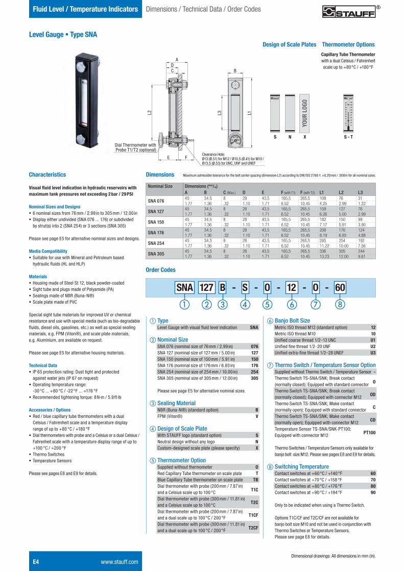
Level Gauge § Type SNA
Characteristics
Visual fluid level indication in hydraulic reservoirs with maximum tank pressures not exceeding 2 bar / 29 PSI
Nominal Sizes and Designs § 6 nominal sizes from 76 mm / 2.99 in to 305 mm / 12.00 in § Display either undivided (SNA 076 ... 176) or subdivided by strut(s) into 2 (SNA 254) or 3 sections (SNA 305)
Please see page E5 for alternative nominal sizes and designs.
Media Compatibility § Suitable for use with Mineral and Petroleum based hydraulic fluids (HL and HLP)
Materials § Housing made of Steel St 12, black powder-coated § Sight tube and plugs made of Polyamide (PA) § Sealings made of NBR (Buna-N®) § Scale plate made of PVC
Special sight tube materials for improved UV or chemical resistance and use with special media (such as bio-degradable fluids, diesel oils, gasolines, etc.) as well as special sealing materials, e.g. FPM (Viton®), and scale plate materials, e.g. Aluminium, are available on request.
Please see page E5 for alternative housing materials.
Technical Data § IP 65 protection rating: Dust tight and protected against water jets (IP 67 on request)
§ Operating temperature range: -30 °C ... +80 °C / -22 °F ... +176 °F
§ Recommended tightening torque: 8 N·m / 5.9 ft·lb
Accessories / Options § Red / blue capillary tube thermometers with a dual Celsius / Fahrenheit scale and a temperature display range of up to +80 °C / +180 °F
§ Dial thermometers with probe and a Celsius or a dual Celsius / Fahrenheit scale with a temperature display range of up to +100 °C / +200 °F
§ Thermo Switches § Temperature Sensors
Please see pages E8 and E9 for details.
100
806040
20
0
B
L3 L1L2
ADC
E F
Dial Thermometer with Probe T1/T2 (optional)
20
40
60
80
100
120
140
160
180
F-10
0
10
20
30
40
50
60
70
80
C
Design of Scale Plates
S X S - T
Thermometer Options
N
Dimensions
Nominal Size Dimensions (mm/in)A B C (Max.) D E F (with T1) F (with T2) L1 L2 L3
SNA 076 45 34,5 8 28 43,5 165,5 265,5 108 76 311.77 1.36 .32 1.10 1.71 6.52 10.45 4.25 2.99 1.22
SNA 127 45 34,5 8 28 43,5 165,5 265,5 159 127 761.77 1.36 .32 1.10 1.71 6.52 10.45 6.26 5.00 2.99
SNA 150 45 34,5 8 28 43,5 165,5 265,5 182 150 991.77 1.36 .32 1.10 1.71 6.52 10.45 7.17 5.91 3.90
SNA 176 45 34,5 8 28 43,5 165,5 265,5 208 176 1241.77 1.36 .32 1.10 1.71 6.52 10.45 8.19 6.93 4.88
SNA 254 45 34,5 8 28 43,5 165,5 265,5 285 254 1921.77 1.36 .32 1.10 1.71 6.52 10.45 11.22 10.00 7.56
SNA 305 45 34,5 8 28 43,5 165,5 265,5 336 305 2441.77 1.36 .32 1.10 1.71 6.52 10.45 13.23 12.00 9.61
Capillary Tube Thermometer with a dual Celsius / Fahrenheit scale up to +80 °C / +180 °F
SNA 127 B - S - O - 12 - O - 60
a Type Level Gauge with visual fluid level indication SNA
b Nominal Size SNA 076 (nominal size of 76 mm / 2.99 in) 076 SNA 127 (nominal size of 127 mm / 5.00 in) 127 SNA 150 (nominal size of 150 mm / 5.91 in) 150 SNA 176 (nominal size of 176 mm / 6.93 in) 176 SNA 254 (nominal size of 254 mm / 10.00 in) 254 SNA 305 (nominal size of 305 mm / 12.00 in) 305
Please see page E5 for alternative nominal sizes.
c Sealing Material NBR (Buna-N®) (standard option) B FPM (Viton®) V
d Design of Scale Plate With STAUFF logo (standard option) S Neutral design without any logo N Custom-designed scale plate (please specify) X
e Thermometer Option Supplied without thermometer O Red Capillary Tube thermometer on scale plate T Blue Capillary Tube thermometer on scale plate TB Dial thermometer with probe (200 mm / 7.87 in) and a Celsius scale up to 100 °C T1C
Dial thermometer with probe (300 mm / 11.81 in) and a Celsius scale up to 100 °C T2C
Dial thermometer with probe (200 mm / 7.87 in) and a dual scale up to 100 °C / 200 °F T1CF
Dial thermometer with probe (300 mm / 11.81 in) and a dual scale up to 100 °C / 200 °F T2CF
f Banjo Bolt Size Metric ISO thread M12 (standard option) 12 Metric ISO thread M10 10 Unified coarse thread 1/2–13 UNC U1 Unified fine thread 1/2–20 UNF U2 Unified extra-fine thread 1/2–28 UNEF U3
g Thermo Switch / Temperature Sensor Option Supplied without Thermo Switch / Temperature Sensor - Thermo Switch TS-SNA/SNK; Break contact (normally closed); Equipped with standard connector O
Thermo Switch TS-SNA/SNK; Break contact (normally closed); Equipped with connector M12 OD
Thermo Switch TS-SNA/SNK; Make contact (normally open); Equipped with standard connector C
Thermo Switch TS-SNA/SNK; Make contact (normally open); Equipped with connector M12 CD
Temperature Sensor TS-SNA/SNK-PT100; Equipped with connector M12 PT100
Thermo Switches / Temperature Sensors only available for banjo bolt size M12. Please see pages E8 and E9 for details.
h Switching Temperature Contact switches at +60 °C / +140 °F 60 Contact switches at +70 °C / +158 °F 70 Contact switches at +80 °C / +176 °F 80 Contact switches at +90 °C / +194 °F 90
Only to be indicated when using a Thermo Switch.
Options T1C/CF and T2C/CF are not available for banjo bolt size M10 and not be used in conjunction with Thermo Switches or Temperature Sensors. Please see page E8 for details.
Order Codes
Maximum admissible tolerance for the bolt center spacing (dimension L2) according to DIN ISO 2768-f: ±0,20 mm / .008 in for all nominal sizes.
Dimensional drawings: All dimensions in mm (in).
Dimensions / Technical Data / Order Codes
YOUR
LOG
O
Clearance Hole: Ø13 (Ø.51) for M12 / Ø10,5 (Ø.41) for M10 / Ø13,5 (Ø.53) for UNC, UNF and UNEF
STAUFF ONE - Hydraulic Accessories - English.indd 4 23.11.2013 12:33:12
Hydr
aulic
Ac
cess
orie
sE
Also available:
Level Gauges § Type SNK in Special Lengths
Visual / electrical fluid level indication in hydraulic reservoirs with level gauges up to a maximum nominal size of 950 mm / 37.4 in.
Please do not hesitate to contact STAUFF for further details.
Fluid Level / Temperature IndicatorsSpecial Options: Characteristics / Inquiry Checklist
www.stauff.com E5
Level Gauge (Special Options) § Type SNA/SNK
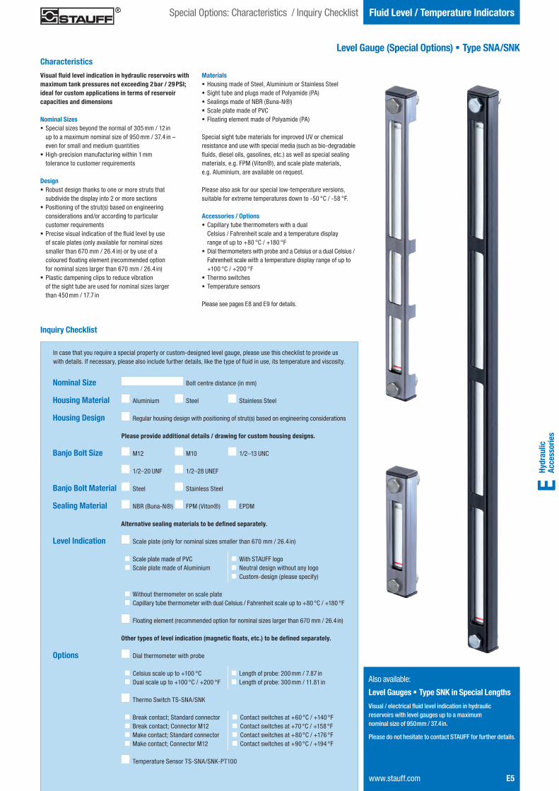
Visual fluid level indication in hydraulic reservoirs with maximum tank pressures not exceeding 2 bar / 29 PSI; ideal for custom applications in terms of reservoir capacities and dimensions
Nominal Sizes § Special sizes beyond the normal of 305 mm / 12 in up to a maximum nominal size of 950 mm / 37.4 in – even for small and medium quantities
§ High-precision manufacturing within 1 mm tolerance to customer requirements
Design § Robust design thanks to one or more struts that subdivide the display into 2 or more sections
§ Positioning of the strut(s) based on engineering considerations and/or according to particular customer requirements
§ Precise visual indication of the fluid level by use of scale plates (only available for nominal sizes smaller than 670 mm / 26.4 in) or by use of a coloured floating element (recommended option for nominal sizes larger than 670 mm / 26.4 in)
§ Plastic dampening clips to reduce vibration of the sight tube are used for nominal sizes larger than 450 mm / 17.7 in
Materials § Housing made of Steel, Aluminium or Stainless Steel § Sight tube and plugs made of Polyamide (PA) § Sealings made of NBR (Buna-N®) § Scale plate made of PVC § Floating element made of Polyamide (PA)
Special sight tube materials for improved UV or chemical resistance and use with special media (such as bio-degradable fluids, diesel oils, gasolines, etc.) as well as special sealing materials, e.g. FPM (Viton®), and scale plate materials, e.g. Aluminium, are available on request.
Please also ask for our special low-temperature versions, suitable for extreme temperatures down to -50 °C / -58 °F.
Accessories / Options § Capillary tube thermometers with a dual Celsius / Fahrenheit scale and a temperature display range of up to +80 °C / +180 °F
§ Dial thermometers with probe and a Celsius or a dual Celsius / Fahrenheit scale with a temperature display range of up to +100 °C / +200 °F
§ Thermo switches § Temperature sensors
Please see pages E8 and E9 for details.
Characteristics
Inquiry Checklist
Nominal Size
Housing Material
Housing Design
Banjo Bolt Size
Banjo Bolt Material
Sealing Material
Level Indication
Options
Aluminium Steel Stainless Steel
Steel Stainless Steel
Bolt centre distance (in mm)
NBR (Buna-N®) FPM (Viton®) EPDM
M12 M10 1/2–13 UNC
1/2–20 UNF 1/2–28 UNEF
Scale plate made of PVC
Floating element (recommended option for nominal sizes larger than 670 mm / 26.4 in)
Scale plate (only for nominal sizes smaller than 670 mm / 26.4 in)
Alternative sealing materials to be defined separately.
Other types of level indication (magnetic floats, etc.) to be defined separately.
Scale plate made of Aluminium
Regular housing design with positioning of strut(s) based on engineering considerations
Please provide additional details / drawing for custom housing designs.
Without thermometer on scale plateCapillary tube thermometer with dual Celsius / Fahrenheit scale up to +80 °C / +180 °F
Length of probe: 200 mm / 7.87 in
Dial thermometer with probe
Length of probe: 300 mm / 11.81 inCelsius scale up to +100 °CDual scale up to +100 °C / +200 °F
Thermo Switch TS-SNA/SNK
Break contact; Standard connectorBreak contact; Connector M12Make contact; Standard connectorMake contact; Connector M12
Contact switches at +60 °C / +140 °FContact switches at +70 °C / +158 °FContact switches at +80 °C / +176 °FContact switches at +90 °C / +194 °F
Temperature Sensor TS-SNA/SNK-PT100
In case that you require a special property or custom-designed level gauge, please use this checklist to provide us with details. If necessary, please also include further details, like the type of fluid in use, its temperature and viscosity.
With STAUFF logoNeutral design without any logoCustom-design (please specify)
STAUFF ONE - Hydraulic Accessories - English.indd 5 23.11.2013 12:33:15
Fluid Level / Temperature Indicators
E6 www.stauff.com
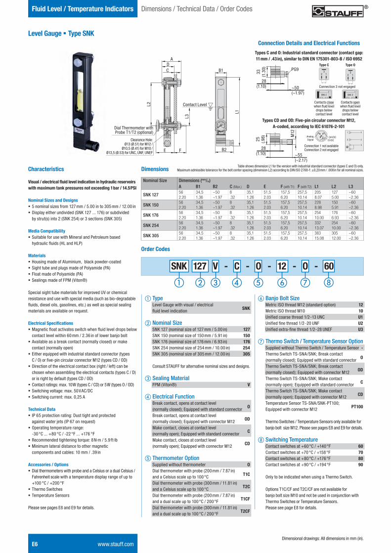
Level Gauge § Type SNK
Characteristics
Visual / electrical fluid level indication in hydraulic reservoirs with maximum tank pressures not exceeding 1 bar / 14.5 PSI
Nominal Sizes and Designs § 5 nominal sizes from 127 mm / 5.00 in to 305 mm / 12.00 in § Display either undivided (SNK 127 ... 176) or subdivided by strut(s) into 2 (SNK 254) or 3 sections (SNK 305)
Media Compatibility § Suitable for use with Mineral and Petroleum based hydraulic fluids (HL and HLP)
Materials § Housing made of Aluminium, black powder-coated § Sight tube and plugs made of Polyamide (PA) § Float made of Polyamide (PA) § Sealings made of FPM (Viton®)
Special sight tube materials for improved UV or chemical resistance and use with special media (such as bio-degradable fluids, diesel oils, gasolines, etc.) as well as special sealing materials are available on request.
Electrical Specifications § Magnetic float activates switch when fluid level drops below contact level within 60 mm / 2.36 in of lower banjo bolt
§ Available as a break contact (normally closed) or make contact (normally open)
§ Either equipped with industrial standard connector (types C / O) or five-pin circular connector M12 (types CD / OD)
§ Direction of the electrical contact box (right / left) can be chosen when assembling the electrical contacts (types C / D) or is right by default (types CD / OD)
§ Contact ratings: max. 10 W (types C / CD) or 5 W (types O / OD) § Switching voltage: max. 50 V AC/DC § Switching current: max. 0,25 A
Technical Data § IP 65 protection rating: Dust tight and protected against water jets (IP 67 on request)
§ Operating temperature range: -30 °C ... +80 °C / -22 °F ... +176 °F
§ Recommended tightening torque: 8 N·m / 5.9 ft·lb § Minimum lateral distance to other magnetic components and cables: 10 mm / .39 in
Accessories / Options § Dial thermometers with probe and a Celsius or a dual Celsius / Fahrenheit scale with a temperature display range of up to +100 °C / +200 °F
§ Thermo Switches § Temperature Sensors
Please see pages E8 and E9 for details.
Dimensions
Nominal Size Dimensions (mm/in)A B1 B2 C (Max.) D E F (with T1) F (with T2) L1 L2 L3
SNK 127 56 34,5 ~50 8 35,1 51,5 157,5 257,5 205 127 ~602.20 1.36 ~1.97 .32 1.26 2.03 6.20 10.14 8.07 5.00 ~2.36
SNK 150 56 34,5 ~50 8 35,1 51,5 157,5 257,5 228 150 ~602.20 1.36 ~1.97 .32 1.26 2.03 6.20 10.14 8.98 5.91 ~2.36
SNK 176 56 34,5 ~50 8 35,1 51,5 157,5 257,5 254 176 ~602.20 1.36 ~1.97 .32 1.26 2.03 6.20 10.14 10.00 6.93 ~2.36
SNK 254 56 34,5 ~50 8 35,1 51,5 157,5 257,5 332 254 ~602.20 1.36 ~1.97 .32 1.26 2.03 6.20 10.14 13.07 10.00 ~2.36
SNK 305 56 34,5 ~50 8 35,1 51,5 157,5 257,5 383 305 ~602.20 1.36 ~1.97 .32 1.26 2.03 6.20 10.14 15.08 12.00 ~2.36
Connection Details and Electrical Functions
Types C and O: Industrial standard connector (contact gap: 11 mm / .43 in), similar to DIN EN 175301-803-B / ISO 6952
Types CD and OD: Five-pin circular connector M12, A-coded, according to IEC 61076-2-101
SNK-C SNK-O
Type C Type O
Contacts close when fluid level
drops below contact level
Contacts open when fluid level
drops below contact level
A
B1
L2
L1
DC
E F
Dial Thermometer with Probe T1/T2 (optional)
B2
L3
Contact Level
13
2 13
2
Table shows dimension L1 for the version with industrial standard connector (types C and O) only. Maximum admissible tolerance for the bolt center spacing (dimension L2) according to DIN ISO 2768-f: ±0,20 mm / .008 in for all nominal sizes.
PG9
Connection 3 not engaged~50(~1.97)
28(1.10)
33(1
.30)
M12
28(1.10) ~55
(~2.17)
25 (.98) Analog
Signal24 V DC
0 V DC
Connection 1 not available Connection 2 not engaged
SNK 127 V - C - O - 12 - O - 60
f Banjo Bolt Size Metric ISO thread M12 (standard option) 12 Metric ISO thread M10 10 Unified coarse thread 1/2–13 UNC U1 Unified fine thread 1/2–20 UNF U2 Unified extra-fine thread 1/2–28 UNEF U3
g Thermo Switch / Temperature Sensor Option Supplied without Thermo Switch / Temperature Sensor - Thermo Switch TS-SNA/SNK; Break contact (normally closed); Equipped with standard connector O
Thermo Switch TS-SNA/SNK; Break contact (normally closed); Equipped with connector M12 OD
Thermo Switch TS-SNA/SNK; Make contact (normally open); Equipped with standard connector C
Thermo Switch TS-SNA/SNK; Make contact (normally open); Equipped with connector M12 CD
Temperature Sensor TS-SNA/SNK-PT100; Equipped with connector M12 PT100
Thermo Switches / Temperature Sensors only available for banjo bolt size M12. Please see pages E8 and E9 for details.
h Switching Temperature Contact switches at +60 °C / +140 °F 60 Contact switches at +70 °C / +158 °F 70 Contact switches at +80 °C / +176 °F 80 Contact switches at +90 °C / +194 °F 90
Only to be indicated when using a Thermo Switch.
Options T1C/CF and T2C/CF are not available for banjo bolt size M10 and not be used in conjunction with Thermo Switches or Temperature Sensors. Please see page E8 for details.
Order Codes
a Type Level Gauge with visual / electrical fluid level indication SNK
b Nominal Size SNK 127 (nominal size of 127 mm / 5.00 in) 127 SNK 150 (nominal size of 150 mm / 5.91 in) 150 SNK 176 (nominal size of 176 mm / 6.93 in) 176 SNK 254 (nominal size of 254 mm / 10.00 in) 254 SNK 305 (nominal size of 305 mm / 12.00 in) 305
Consult STAUFF for alternative nominal sizes and designs.
c Sealing Material FPM (Viton®) V
d Electrical Function Break contact, opens at contact level (normally closed); Equipped with standard connector O
Break contact, opens at contact level (normally closed); Equipped with connector M12 OD
Make contact, closes at contact level (normally open); Equipped with standard connector C
Make contact, closes at contact level (normally open); Equipped with connector M12 CD
e Thermometer Option Supplied without thermometer O Dial thermometer with probe (200 mm / 7.87 in) and a Celsius scale up to 100 °C T1C
Dial thermometer with probe (300 mm / 11.81 in) and a Celsius scale up to 100 °C T2C
Dial thermometer with probe (200 mm / 7.87 in) and a dual scale up to 100 °C / 200 °F T1CF
Dial thermometer with probe (300 mm / 11.81 in) and a dual scale up to 100 °C / 200 °F T2CF
Dimensional drawings: All dimensions in mm (in).
Dimensions / Technical Data / Order Codes
Clearance Hole: Ø13 (Ø.51) for M12 /
Ø10,5 (Ø.41) for M10 / Ø13,5 (Ø.53) for UNC, UNF, UNEF
STAUFF ONE - Hydraulic Accessories - English.indd 6 23.11.2013 12:33:21
Hydr
aulic
Ac
cess
orie
sE
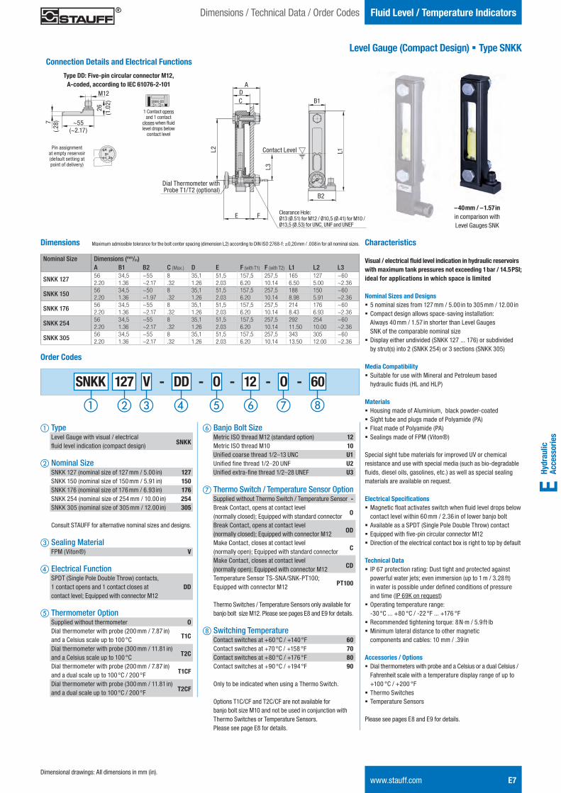
Level Gauge (Compact Design) § Type SNKK
Fluid Level / Temperature Indicators
www.stauff.com E7
Characteristics
Visual / electrical fl uid level indication in hydraulic reservoirs with maximum tank pressures not exceeding 1 bar / 14.5 PSI; ideal for applications in which space is limited
Nominal Sizes and Designs § 5 nominal sizes from 127 mm / 5.00 in to 305 mm / 12.00 in § Compact design allows space-saving installation: Always 40 mm / 1.57 in shorter than Level Gauges SNK of the comparable nominal size
§ Display either undivided (SNKK 127 ... 176) or subdividedby strut(s) into 2 (SNKK 254) or 3 sections (SNKK 305)
Media Compatibility§ Suitable for use with Mineral and Petroleum based
hydraulic fl uids (HL and HLP)
Materials § Housing made of Aluminium, black powder-coated § Sight tube and plugs made of Polyamide (PA) § Float made of Polyamide (PA) § Sealings made of FPM (Viton®)
Special sight tube materials for improved UV or chemical resistance and use with special media (such as bio-degradable fl uids, diesel oils, gasolines, etc.) as well as special sealing materials are available on request.
Electrical Specifi cations § Magnetic fl oat activates switch when fl uid level drops below contact level within 60 mm / 2.36 in of lower banjo bolt
§ Available as a SPDT (Single Pole Double Throw) contact § Equipped with fi ve-pin circular connector M12 § Direction of the electrical contact box is right to top by default
Technical Data § IP 67 protection rating: Dust tight and protected againstpowerful water jets; even immersion (up to 1 m / 3.28 ft) in water is possible under defi ned conditions of pressure and time (IP 69K on request)
§ Operating temperature range: -30 °C ... +80 °C / -22 °F ... +176 °F
§ Recommended tightening torque: 8 N·m / 5.9 ft·lb § Minimum lateral distance to other magnetic components and cables: 10 mm / .39 in
Accessories / Options § Dial thermometers with probe and a Celsius or a dual Celsius / Fahrenheit scale with a temperature display range of up to +100 °C / +200 °F
§ Thermo Switches § Temperature Sensors
Please see pages E8 and E9 for details.
Dimensions
Nominal Size Dimensions (mm/in)A B1 B2 C (Max.) D E F (with T1) F (with T2) L1 L2 L3
SNKK 127 56 34,5 ~55 8 35,1 51,5 157,5 257,5 165 127 ~602.20 1.36 ~2.17 .32 1.26 2.03 6.20 10.14 6.50 5.00 ~2.36
SNKK 150 56 34,5 ~50 8 35,1 51,5 157,5 257,5 188 150 ~602.20 1.36 ~1.97 .32 1.26 2.03 6.20 10.14 8.98 5.91 ~2.36
SNKK 176 56 34,5 ~55 8 35,1 51,5 157,5 257,5 214 176 ~602.20 1.36 ~2.17 .32 1.26 2.03 6.20 10.14 8.43 6.93 ~2.36
SNKK 254 56 34,5 ~55 8 35,1 51,5 157,5 257,5 292 254 ~602.20 1.36 ~2.17 .32 1.26 2.03 6.20 10.14 11.50 10.00 ~2.36
SNKK 305 56 34,5 ~55 8 35,1 51,5 157,5 257,5 343 305 ~602.20 1.36 ~2.17 .32 1.26 2.03 6.20 10.14 13.50 12.00 ~2.36
SNKK 127 V - DD - O - 12 - O - 60
f Banjo Bolt Size Metric ISO thread M12 (standard option) 12 Metric ISO thread M10 10 Unifi ed coarse thread 1/2–13 UNC U1 Unifi ed fi ne thread 1/2–20 UNF U2 Unifi ed extra-fi ne thread 1/2–28 UNEF U3
g Thermo Switch / Temperature Sensor Option Supplied without Thermo Switch / Temperature Sensor - Break Contact, opens at contact level (normally closed); Equipped with standard connector O
Break Contact, opens at contact level (normally closed); Equipped with connector M12 OD
Make Contact, closes at contact level (normally open); Equipped with standard connector C
Make Contact, closes at contact level (normally open); Equipped with connector M12 CD
Temperature Sensor TS-SNA/SNK-PT100; Equipped with connector M12 PT100
Thermo Switches / Temperature Sensors only available for banjo bolt size M12. Please see pages E8 and E9 for details.
h Switching Temperature Contact switches at +60 °C / +140 °F 60 Contact switches at +70 °C / +158 °F 70 Contact switches at +80 °C / +176 °F 80 Contact switches at +90 °C / +194 °F 90
Only to be indicated when using a Thermo Switch.
Options T1C/CF and T2C/CF are not available for banjo bolt size M10 and not be used in conjunction with Thermo Switches or Temperature Sensors. Please see page E8 for details.
Order Codes
a Type Level Gauge with visual / electrical fl uid level indication (compact design) SNKK
b Nominal Size SNKK 127 (nominal size of 127 mm / 5.00 in) 127 SNKK 150 (nominal size of 150 mm / 5.91 in) 150 SNKK 176 (nominal size of 176 mm / 6.93 in) 176 SNKK 254 (nominal size of 254 mm / 10.00 in) 254 SNKK 305 (nominal size of 305 mm / 12.00 in) 305
Consult STAUFF for alternative nominal sizes and designs.
c Sealing Material FPM (Viton®) V
d Electrical Function SPDT (Single Pole Double Throw) contacts, 1 contact opens and 1 contact closes at DD contact level; Equipped with connector M12
e Thermometer Option Supplied without thermometer O Dial thermometer with probe (200 mm / 7.87 in) and a Celsius scale up to 100 °C T1C
Dial thermometer with probe (300 mm / 11.81 in) and a Celsius scale up to 100 °C T2C
Dial thermometer with probe (200 mm / 7.87 in) and a dual scale up to 100 °C / 200 °F T1CF
Dial thermometer with probe (300 mm / 11.81 in) and a dual scale up to 100 °C / 200 °F T2CF
Connection Details and Electrical Functions
Type DD: Five-pin circular connector M12, A-coded, according to IEC 61076-2-101 A
B1
L2 L1
DC
E F
B2
L3
Contact Level
~55(~2.17)
26(1
.02)
M12
7(.2
8)
Maximum admissible tolerance for the bolt center spacing (dimension L2) according to DIN ISO 2768-f: ±0,20 mm / .008 in for all nominal sizes.
Dimensional drawings: All dimensions in mm (in).
Dimensions / Technical Data / Order Codes
– 40 mm / – 1.57 in in comparison with Level Gauges SNK
1 Contact opens and 1 contact
closes when fl uid level drops below
contact level
1
Pin assignment at empty reservoir(default setting atpoint of delivery)
Clearance Hole: Ø13 (Ø.51) for M12 / Ø10,5 (Ø.41) for M10 / Ø13,5 (Ø.53) for UNC, UNF and UNEF
Dial Thermometer with Probe T1/T2 (optional)
STAUFF ONE - Hydraulic Accessories - English.indd 7 23.11.2013 12:33:24
E8 www.stauff.com
Fluid Level / Temperature Indicators
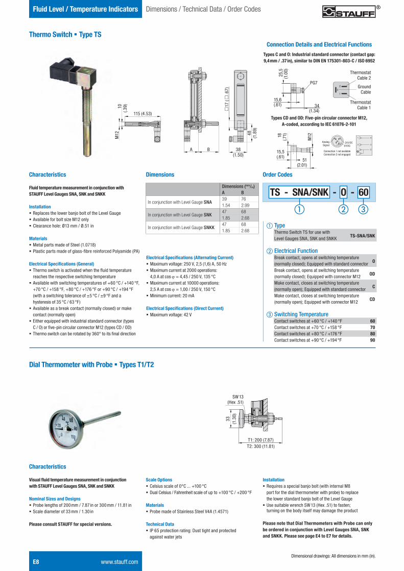
Thermo Switch § Type TSConnection Details and Electrical Functions
Types C and O: Industrial standard connector (contact gap: 9,4 mm / .37 in), similar to DIN EN 175301-803-C / ISO 6952
Types CD and OD: Five-pin circular connector M12, A-coded, according to IEC 61076-2-101
PG7
34(1.34)
Characteristics
Fluid temperature measurement in conjunction with STAUFF Level Gauges SNA, SNK and SNKK
Installation § Replaces the lower banjo bolt of the Level Gauge § Available for bolt size M12 only § Clearance hole: Ø13 mm / Ø.51 in
Materials § Metal parts made of Steel (1.0718) § Plastic parts made of glass-fibre reinforced Polyamide (PA)
Electrical Specifications (General) § Thermo switch is activated when the fluid temperature reaches the respective switching temperature
§ Available with switching temperatures of +60 °C / +140 °F, +70 °C / +158 °F, +80 °C / +176 °F or +90 °C / +194 °F (with a switching tolerance of ±5 °C / ±9 °F and a hysteresis of 35 °C / 63 °F)
§ Available as a break contact (normally closed) or make contact (normally open)
§ Either equipped with industrial standard connector (types C / O) or five-pin circular connector M12 (types CD / OD)
§ Thermo switch can be rotated by 360° to its final direction
TS - SNA/SNK - O - 60
Order Codes
a Type Thermo Switch TS for use with Level Gauges SNA, SNK and SNKK TS-SNA/SNK
b Electrical Function Break contact, opens at switching temperature (normally closed); Equipped with standard connector O
Break contact, opens at switching temperature (normally closed); Equipped with connector M12 OD
Make contact, closes at switching temperature (normally open); Equipped with standard connector C
Make contact, closes at switching temperature (normally open); Equipped with connector M12 CD
c Switching Temperature Contact switches at +60 °C / +140 °F 60 Contact switches at +70 °C / +158 °F 70 Contact switches at +80 °C / +176 °F 80 Contact switches at +90 °C / +194 °F 90
Dial Thermometer with Probe § Types T1/T2
Dimensions
Dimensions (mm/in)A B
In conjunction with Level Gauge SNA39 761.54 2.99
In conjunction with Level Gauge SNK47 681.85 2.68
In conjunction with Level Gauge SNKK47 681.85 2.68
115 (4.53)M
1210
(.39)
c17
(c
.67)
48
(1.8
9)
38 (1.50)
A B
Characteristics
Visual fluid temperature measurement in conjunction with STAUFF Level Gauges SNA, SNK and SNKK
Nominal Sizes and Designs § Probe lengths of 200 mm / 7.87 in or 300 mm / 11.81 in § Scale diameter of 33 mm / 1.30 in
Please consult STAUFF for special versions.
Scale Options § Celsius scale of 0°C ... +100 °C § Dual Celsius / Fahrenheit scale of up to +100 °C / +200 °F
Materials § Probe made of Stainless Steel V4A (1.4571)
Technical Data § IP 65 protection rating: Dust tight and protected against water jets
T1: 200 (7.87)T2: 300 (11.81)
33(1
.30)
15,6(.61)
25,5
(1.0
0)
Electrical Specifications (Alternating Current) § Maximum voltage: 250 V, 2,5 (1,6) A, 50 Hz § Maximum current at 2000 operations: 4,0 A at cos j = 4,45 / 250 V, 135 °C
§ Maximum current at 10000 operations: 2,5 A at cos j = 1,00 / 250 V, 150 °C
§ Minimum current: 20 mA
Electrical Specifications (Direct Current) § Maximum voltage: 42 V
15,5(.61)
18(.7
1)
M12
51(2.01)
AnalogSignal
24 V DC0 V DC
Connection 1 not available Connection 2 not engaged
1
32
Thermostat Cable 2
Thermostat Cable 1
GroundCable
Dimensional drawings: All dimensions in mm (in).
Dimensions / Technical Data / Order Codes
SW 13(Hex .51)
Installation § Requires a special banjo bolt (with internal M8 port for the dial thermometer with probe) to replace the lower standard banjo bolt of the Level Gauge
§ Use suitable wrench SW 13 (Hex .51) to fasten; turning on the body itself may damage the product
Please note that Dial Thermometers with Probe can only be ordered in conjunction with Level Gauges SNA, SNK and SNKK. Please see page E4 to E7 for details.
STAUFF ONE - Hydraulic Accessories - English.indd 8 23.11.2013 12:33:26
Hydr
aulic
Ac
cess
orie
sE
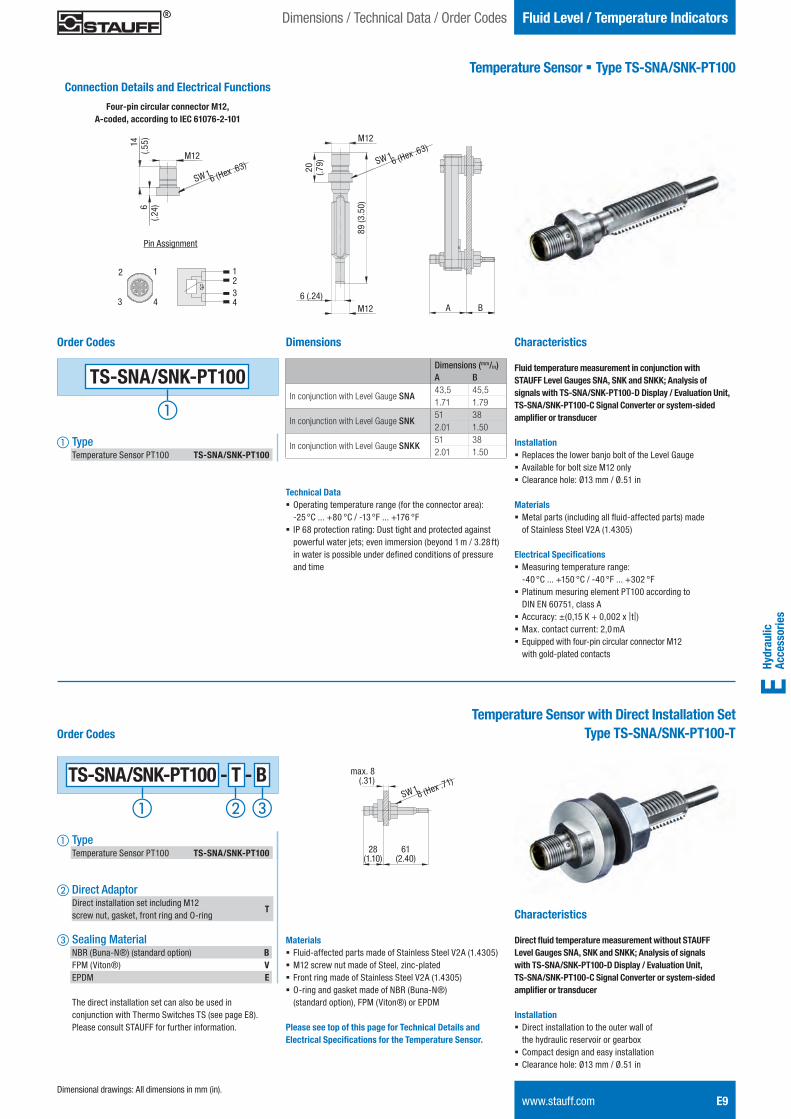
Temperature Sensor § Type TS-SNA/SNK-PT100
Fluid Level / Temperature Indicators
www.stauff.com E9
Dimensions
A B
89 (3
.50)
20 (.79)
M12
M126 (.24)
TS-SNA/SNK-PT100
Order Codes
a Type Temperature Sensor PT100 TS-SNA/SNK-PT100
Connection Details and Electrical Functions
Four-pin circular connector M12, A-coded, according to IEC 61076-2-101
SW 16 (Hex .63)M12
6 (.
24)
14 (.
55)
SW 16 (Hex .63)
2
4
1
3
Pin Assignment
1234
Dimensional drawings: All dimensions in mm (in).
Dimensions / Technical Data / Order Codes
Dimensions (mm/in)A B
In conjunction with Level Gauge SNA43,5 45,51.71 1.79
In conjunction with Level Gauge SNK51 382.01 1.50
In conjunction with Level Gauge SNKK51 382.01 1.50
Technical Data § Operating temperature range (for the connector area): -25 °C ... +80 °C / -13 °F ... +176 °F
§ IP 68 protection rating: Dust tight and protected against powerful water jets; even immersion (beyond 1 m / 3.28 ft) in water is possible under defined conditions of pressure and time
Characteristics
Fluid temperature measurement in conjunction with STAUFF Level Gauges SNA, SNK and SNKK; Analysis of signals with TS-SNA/SNK-PT100-D Display / Evaluation Unit, TS-SNA/SNK-PT100-C Signal Converter or system-sided amplifier or transducer
Installation § Replaces the lower banjo bolt of the Level Gauge § Available for bolt size M12 only § Clearance hole: Ø13 mm / Ø.51 in
Materials § Metal parts (including all fluid-affected parts) made of Stainless Steel V2A (1.4305)
Electrical Specifications § Measuring temperature range: -40 °C ... +150 °C / -40 °F ... +302 °F
§ Platinum mesuring element PT100 according to DIN EN 60751, class A
§ Accuracy: ±(0,15 K + 0,002 x |t|) § Max. contact current: 2,0 mA § Equipped with four-pin circular connector M12 with gold-plated contacts
Temperature Sensor with Direct Installation SetType TS-SNA/SNK-PT100-T
Characteristics
Direct fluid temperature measurement without STAUFF Level Gauges SNA, SNK and SNKK; Analysis of signals with TS-SNA/SNK-PT100-D Display / Evaluation Unit, TS-SNA/SNK-PT100-C Signal Converter or system-sided amplifier or transducer
Installation § Direct installation to the outer wall of the hydraulic reservoir or gearbox
§ Compact design and easy installation § Clearance hole: Ø13 mm / Ø.51 in
max. 8(.31)
Order Codes
a Type Temperature Sensor PT100 TS-SNA/SNK-PT100
b Direct Adaptor Direct installation set including M12 screw nut, gasket, front ring and O-ring
T
c Sealing Material NBR (Buna-N®) (standard option) B FPM (Viton®) V EPDM E
The direct installation set can also be used in conjunction with Thermo Switches TS (see page E8). Please consult STAUFF for further information.
TS-SNA/SNK-PT100 - T - B
28(1.10)
61(2.40)
SW 18 (Hex .71)
Materials § Fluid-affected parts made of Stainless Steel V2A (1.4305) § M12 screw nut made of Steel, zinc-plated § Front ring made of Stainless Steel V2A (1.4305) § O-ring and gasket made of NBR (Buna-N®) (standard option), FPM (Viton®) or EPDM
Please see top of this page for Technical Details and Electrical Specifications for the Temperature Sensor.
STAUFF ONE - Hydraulic Accessories - English.indd 9 23.11.2013 12:33:29
E10 www.stauff.com
Dimensions / Technical Data / Order CodesFluid Level / Temperature Indicators
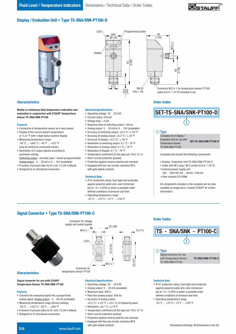
Display / Evaluation Unit § Type TS-SNA/SNK-PT100-D
Characteristics
Mobile or stationary fluid temperature indication and evaluation in conjunction with STAUFF Temperature Sensor TS-SNA/SNK-PT100
Features § Connection of temperature sensor as 4-wire sensor § Display of the current system temperature in °C or °F with 4-digit alpha-numeric display
§ Measuring temperature range: -40 °C ... +300 °C / -40 °F ... +572 °F (may be limited by connected sensor)
§ Generation of 2 output signals according to parameter setting: Switching output - normally open / closed (programmable) Analog output - 4 ... 20 mA or 0 ... 10 V (scaleable)
§ Provision of process data via IO-Link 1.0 (38.4 kBaud) § Designed for bi-directional connection
48(1.89)
Programming button
SW 30 (Hex 1.18)
LED’s
Display
G1/2
93
(3.6
6)
Ø34(Ø1.34)
16,5
(.6
5)
Connector M12 x 1 for temperature sensor PT100; cable (0,6 m / 1.97 ft) included in set
60
(2.3
6)
M12
x 1
SET-TS-SNA/SNK-PT100-D
Order Codes
a Type Complete set of Display / Evaluation Unit for use with Temperature Sensor
SET-TS-SNA/SNK-PT100-D
TS-SNA/SNK-PT100
Complete sets include the following components: § Display / Evaluation Unit TS-SNA/SNK-PT100-D § Cable with M12 plug / M12 socket (0,6 m / 1.97 ft) § External power supply unit 100 ... 240 V AC (50 ... 60 Hz) / 200 mA § User manual (CD-ROM)
All components included in the complete set are also available as single parts. Consult STAUFF for further information.
Signal Convertor § Type TS-SNA/SNK-PT100-C
Electrical Specifications § Operating voltage: 18 ... 32 V DC § Current rating: 250 mA § Voltage drop: <2 mA § Response time of switching output: 130 ms § Analog output: 4 ... 20 mA or 0 ... 10 V (scaleable) § Accuracy of switching output: ±0,3 °C / ±.54 °F § Accuracy of analog output: ±0,3 °C / ±.54 °F § Accuracy of display: ±0,3 °C / ±.54 °F § Resolution of switching output: 0,1 °C / .18 °F § Resolution of analog output: 0,1 °C / .18 °F § Resolution of display: 0,1 °C / .18 °F § Temperature coefficient (of the span per 10 K): 0,1 % § Short-circuit protection (pulsed) § Protection against reverse polarity and overload § Equipped with four-pin circular connector M12 with gold-plated contacts
Technical Data § IP 67 protection rating: Dust tight and protected against powerful water jets; even immersion (up to 1 m / 3.28 ft) in water is possible under defined conditions of pressure and time
§ Operating temperature range: -25 °C ... +70 °C / -13 °F ... +158 °F
Characteristics
Signal convertor for use with STAUFF Temperature Sensor TS-SNA/SNK-PT100
Features § Converts the measured signal into a proportional analog signal: Analog output - 4 ... 20 mA (scaleable)
§ Measuring temperature range (factory setting): -50 °C ... +150 °C / -58 °F ... +302 °F
§ Provision of process data via IO-Link 1.0 (38.4 kBaud) § Designed for bi-directional connection
Electrical Specifications § Operating voltage: 20 ... 32 V DC § Analog output: 4 ... 20 mA (scaleable) § Maximum load: 300 Ω § Rise time analog output: 400 ms § Accuracy of analog output: ±0,3 °C / ±.54 °F + (±0,1 % of measuring span)
§ Resolution: ≤0,1 °C / ≤.18 °F § Temperature coefficient (of the span per 10 K): 0,1 % § Short-circuit protection (pulsed) § Protection against reverse polarity and overload § Equipped with four-pin circular connector M12 with gold-plated contacts
Order Codes
TS - SNA/SNK - PT100-C
a Type Signal Convertor for use with Temperature Sensor TS-SNA/SNK-PT100-C TS-SNA/SNK-PT100
18 (.71)25 (.98)
M12 x 1
M12 x 1
52 (2
.05)
22 (.
87)
Connector for voltage supply and output signals
Connector for temperature sensor PT100
Technical Data § IP 67 protection rating: Dust tight and protected against powerful water jets; even immersion (up to 1 m / 3.28 ft) in water is possible under defined conditions of pressure and time
§ Operating temperature range: -25 °C ... +70 °C / -13 °F ... +158 °F
LED’s
Dimensional drawings: All dimensions in mm (in).
STAUFF ONE - Hydraulic Accessories - English.indd 10 23.11.2013 12:33:30
Hydr
aulic
Ac
cess
orie
sE
www.stauff.com E11
Fluid Level / Temperature IndicatorsDimensions / Technical Data / Order Codes
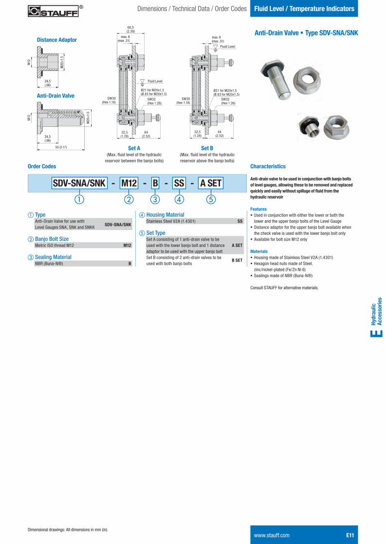
Anti-Drain Valve § Type SDV-SNA/SNK
Characteristics
Anti-drain valve to be used in conjunction with banjo bolts of level gauges, allowing these to be removed and replaced quickly and easily without spillage of fl uid from the hydraulic reservoir
Features § Used in conjunction with either the lower or both the lower and the upper banjo bolts of the Level Gauge
§ Distance adaptor for the upper banjo bolt available when the check valve is used with the lower banjo bolt only
§ Available for bolt size M12 only
Materials§ Housing made of Stainless Steel V2A (1.4301) § Hexagon head nuts made of Steel, zinc/nickel-plated (Fe/Zn Ni 6)
§ Sealings made of NBR (Buna-N®)
Consult STAUFF for alternative materials.
32,5(1.28)
64(2.52)
Ø21 for M20x1,5(Ø.83 for M20x1,5)
Fluid Level
max. 8(max .31)
60,5(2.38)
d Housing Material Stainless Steel V2A (1.4301) SS
e Set Type Set A consisting of 1 anti-drain valve to be used with the lower banjo bolt and 1 distance A SET adaptor to be used with the upper banjo bolt Set B consisting of 2 anti-drain valves to be used with both banjo bolts
B SET
Order Codes
a Type Anti-Drain Valve for use with Level Gauges SNA, SNK and SNKK SDV-SNA/SNK
b Banjo Bolt Size Metric ISO thread M12 M12
c Sealing Material NBR (Buna-N®) B
SDV-SNA/SNK - M12 - B - SS - A SET
32,5(1.28)
64(2.52)
Ø21 for M20x1,5(Ø.83 for M20x1,5)
Fluid Level
max. 8(max .31)
Set B(Max. fl uid level of the hydraulic reservoir above the banjo bolts)
Set A(Max. fl uid level of the hydraulic
reservoir between the banjo bolts)
SW32 (Hex 1.26)
SW32 (Hex 1.26)
SW30 (Hex 1.18)
SW30 (Hex 1.18)
24,5(.96)
M12
M20
×1.5
24,5(.96)
M12
M20
×1.5
55 (2.17)
Distance Adaptor
Anti-Drain Valve
Dimensional drawings: All dimensions in mm (in).
STAUFF ONE - Hydraulic Accessories - English.indd 11 23.11.2013 12:33:32
E12 www.stauff.com
Dimensions / Technical Data / Order CodesTank Filler Breathers
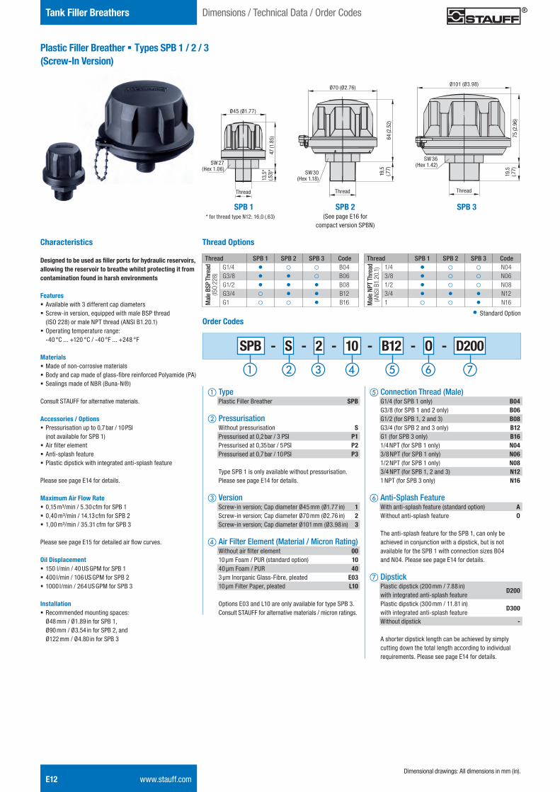
Plastic Filler Breather § Types SPB 1 / 2 / 3(Screw-In Version)
Characteristics
Designed to be used as filler ports for hydraulic reservoirs, allowing the reservoir to breathe whilst protecting it from contamination found in harsh environments
Features § Available with 3 different cap diameters § Screw-in version, equipped with male BSP thread (ISO 228) or male NPT thread (ANSI B1.20.1)
§ Operating temperature range: -40 °C ... +120 °C / -40 °F ... +248 °F
Materials § Made of non-corrosive materials § Body and cap made of glass-fibre reinforced Polyamide (PA) § Sealings made of NBR (Buna-N®)
Consult STAUFF for alternative materials.
Accessories / Options § Pressurisation up to 0,7 bar / 10 PSI (not available for SPB 1)
§ Air filter element § Anti-splash feature § Plastic dipstick with integrated anti-splash feature
Please see page E14 for details.
Maximum Air Flow Rate § 0,15 m³/min / 5.30 cfm for SPB 1 § 0,40 m³/min / 14.13 cfm for SPB 2 § 1,00 m³/min / 35.31 cfm for SPB 3
Please see page E15 for detailed air flow curves.
Oil Displacement § 150 l/min / 40 US GPM for SPB 1 § 400 l/min / 106 US GPM for SPB 2 § 1000 l/min / 264 US GPM for SPB 3
Installation § Recommended mounting spaces: Ø48 mm / Ø1.89 in for SPB 1, Ø90 mm / Ø3.54 in for SPB 2, and Ø122 mm / Ø4.80 in for SPB 3
SW 27 (Hex 1.06)
Ø45 (Ø1.77)
13,5
*(.5
3)*
47 (1
.85)
SW 30(Hex 1.18)
SW 36(Hex 1.42)
Ø70 (Ø2.76)Ø101 (Ø3.98)
19,5
(.77)
19,5
(.77)
64 (2
.52)
75 (2
.96)
Thread Thread Thread
SPB - S - 2 - 10 - B12 - O - D200
e Connection Thread (Male) G1/4 (for SPB 1 only) B04 G3/8 (for SPB 1 and 2 only) B06 G1/2 (for SPB 1, 2 and 3) B08 G3/4 (for SPB 2 and 3 only) B12 G1 (for SPB 3 only) B16 1/4 NPT (for SPB 1 only) N04 3/8 NPT (for SPB 1 only) N06 1/2 NPT (for SPB 1 only) N08 3/4 NPT (for SPB 1, 2 and 3) N12 1 NPT (for SPB 3 only) N16 f Anti-Splash Feature With anti-splash feature (standard option) A Without anti-splash feature O
The anti-splash feature for the SPB 1, can only be achieved in conjunction with a dipstick, but is not available for the SPB 1 with connection sizes B04 and N04. Please see page E14 for details.
g Dipstick Plastic dipstick (200 mm / 7.88 in) with integrated anti-splash feature
D200
Plastic dipstick (300 mm / 11.81 in) with integrated anti-splash feature
D300
Without dipstick -
A shorter dipstick length can be achieved by simply cutting down the total length according to individual requirements. Please see page E14 for details.
Order Codes
a Type Plastic Filler Breather SPB
b Pressurisation Without pressurisation S Pressurised at 0,2 bar / 3 PSI P1 Pressurised at 0,35 bar / 5 PSI P2 Pressurised at 0,7 bar / 10 PSI P3
Type SPB 1 is only available without pressurisation. Please see page E14 for details.
c Version Screw-in version; Cap diameter Ø45 mm (Ø1.77 in) 1 Screw-in version; Cap diameter Ø70 mm (Ø2.76 in) 2 Screw-in version; Cap diameter Ø101 mm (Ø3.98 in) 3
d Air Filter Element (Material / Micron Rating) Without air filter element 00 10 μm Foam / PUR (standard option) 10 40 μm Foam / PUR 40 3 μm Inorganic Glass-Fibre, pleated E03 10 μm Filter Paper, pleated L10
Options E03 and L10 are only available for type SPB 3. Consult STAUFF for alternative materials / micron ratings.
SPB 1 SPB 2(See page E16 for
compact version SPBN)
SPB 3
Thread Options
Thread SPB 1 SPB 2 SPB 3 Code
Mal
e BS
P Th
read
(ISO
228)
G1/4 O o o B04G3/8 O O o B06G1/2 O O O B08G3/4 o O O B12G1 o o O B16
Thread SPB 1 SPB 2 SPB 3 Code
Mal
e NP
T Th
read
(ANS
I B1.
20.1
) 1/4 O o o N043/8 O o o N061/2 O o o N083/4 O O O N121 o o O N16
O Standard Option
Dimensional drawings: All dimensions in mm (in).
* for thread type N12: 16,0 (.63)
STAUFF ONE - Hydraulic Accessories - English.indd 12 23.11.2013 12:33:34
Hydr
aulic
Ac
cess
orie
sE
Tank Filler Breathers
www.stauff.com E13
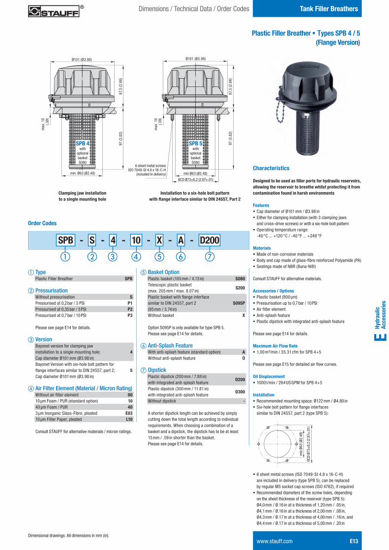
Plastic Filler Breather § Types SPB 4 / 5 (Flange Version)
Dimensions / Technical Data / Order Codes
Characteristics
Designed to be used as filler ports for hydraulic reservoirs, allowing the reservoir to breathe whilst protecting it from contamination found in harsh environments
Features § Cap diameter of Ø101 mm / Ø3.98 in § Either for clamping installation (with 3 clamping jaws and cross-drive screws) or with a six-hole bolt pattern
§ Operating temperature range: -40 °C ... +120 °C / -40 °F ... +248 °F
Materials § Made of non-corrosive materials § Body and cap made of glass-fibre reinforced Polyamide (PA) § Sealings made of NBR (Buna-N®)
Consult STAUFF for alternative materials.
Accessories / Options § Plastic basket (800 μm) § Pressurisation up to 0,7 bar / 10 PSI § Air filter element § Anti-splash feature § Plastic dipstick with integrated anti-splash feature
Please see page E14 for details.
Maximum Air Flow Rate § 1,00 m³/min / 35.31 cfm for SPB 4+5
Please see page E15 for detailed air flow curves.
Oil Displacement § 1000 l/min / 264 US GPM for SPB 4+5
Installation § Recommended mounting space: Ø122 mm / Ø4.80 in § Six-hole bolt pattern for flange interfaces similar to DIN 24557, part 2 (type SPB 5):
§ 6 sheet metal screws (ISO 7049-St 4.8 x 16-C-H) are included in delivery (type SPB 5); can be replaced by regular M5 socket cap screws (ISO 4762), if required
§ Recommended diameters of the screw holes, depending on the sheet thickness of the reservoir (type SPB 5): Ø4,0 mm / Ø.16 in at a thickness of 1,20 mm / .05 in, Ø4,1 mm / Ø.16 in at a thickness of 2,00 mm / .08 in, Ø4,3 mm / Ø.17 in at a thickness of 4,00 mm / .16 in, and Ø4,4 mm / Ø.17 in at a thickness of 5,00 mm / .20 in
SPB 4with
optional basket S080
Ø101 (Ø3.98) Ø101 (Ø3.98)
97 (3
.82)
67,5
(2.6
6)
BCD Ø73±0,2 (2.87±.01)
min Ø63 (Ø2.48)
max
. 10
(.39
)
97 (3
.82)
67,5
(2.6
6)
max
. 10
(.39
)
min. Ø63 (Ø2.48)
6 sheet metal screwsISO 7049-St 4.8 x 16-C-H
(included in delivery)
SPB - S - 4 - 10 - X - A - D200
e Basket Option Plastic basket (105 mm / 4.13 in) S080 Telescopic plastic basket (max. 205 mm / max. 8.07 in)
S200
Plastic basket with flange interface similar to DIN 24557, part 2 S095P (95 mm / 3.74 in) Without basket X
Option S095P is only available for type SPB 5. Please see page E14 for details. f Anti-Splash Feature With anti-splash feature (standard option) A Without anti-splash feature O
g Dipstick Plastic dipstick (200 mm / 7.88 in) with integrated anti-splash feature
D200
Plastic dipstick (300 mm / 11.81 in) with integrated anti-splash feature
D300
Without dipstick -
A shorter dipstick length can be achieved by simply cutting down the total length according to individual requirements. When choosing a combination of a basket and a dipstick, the dipstick has to be at least 15 mm / .59 in shorter than the basket. Please see page E14 for details.
Order Codes
a Type Plastic Filler Breather SPB
b Pressurisation Without pressurisation S Pressurised at 0,2 bar / 3 PSI P1 Pressurised at 0,35 bar / 5 PSI P2 Pressurised at 0,7 bar / 10 PSI P3 Please see page E14 for details.
c Version Bayonet version for clamping jaw installation to a single mounting hole; 4 Cap diameter Ø101 mm (Ø3.98 in) Bayonet Version with six-hole bolt pattern for flange interfaces similar to DIN 24557, part 2; 5 Cap diameter Ø101 mm (Ø3.98 in)
d Air Filter Element (Material / Micron Rating) Without air filter element 00 10 μm Foam / PUR (standard option) 10 40 μm Foam / PUR 40 3 μm Inorganic Glass-Fibre, pleated E03 10 μm Filter Paper, pleated L10
Consult STAUFF for alternative materials / micron ratings.
SPB 5with
optional basket S080
Clamping jaw installation to a single mounting hole
Installation to a six-hole bolt pattern with flange interface similar to DIN 24557, Part 2
BCD
Ø73±
0,2
(2.8
7±.0
1)
min
Ø63
(Ø2.
48)
Dimensional drawings: All dimensions in mm (in).
STAUFF ONE - Hydraulic Accessories - English.indd 13 23.11.2013 12:33:35
E14 www.stauff.com
Accessories / OptionsTank Filler Breathers
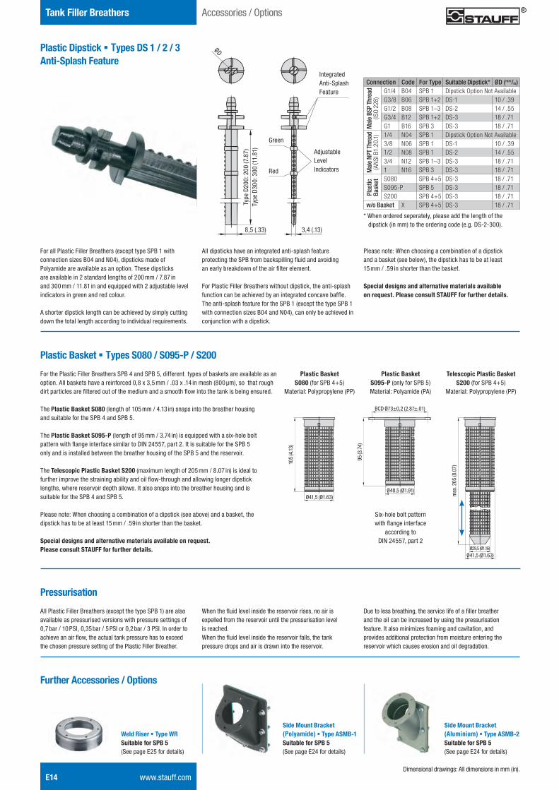
Plastic Dipstick § Types DS 1 / 2 / 3 Anti-Splash Feature
Integrated Anti-Splash Feature
Adjustable Level Indicators
Green
Red
ØD
Type
D20
0: 2
00 (7
.87)
Type
D30
0: 3
00 (1
1.81
)
Dimensional drawings: All dimensions in mm (in).
3,4 (.13)8,5 (.33)
For all Plastic Filler Breathers (except type SPB 1 with connection sizes B04 and N04), dipsticks made of Polyamide are available as an option. These dipsticks are available in 2 standard lengths of 200 mm / 7.87 in and 300 mm / 11.81 in and equipped with 2 adjustable level indicators in green and red colour.
A shorter dipstick length can be achieved by simply cutting down the total length according to individual requirements.
All dipsticks have an integrated anti-splash feature protecting the SPB from backspilling fluid and avoiding an early breakdown of the air filter element.
For Plastic Filler Breathers without dipstick, the anti-splash function can be achieved by an integrated concave baffle.The anti-splash feature for the SPB 1 (except the type SPB 1 with connection sizes B04 and N04), can only be achieved in conjunction with a dipstick.
Please note: When choosing a combination of a dipstick and a basket (see below), the dipstick has to be at least 15 mm / .59 in shorter than the basket.
Special designs and alternative materials available on request. Please consult STAUFF for further details.
Connection Code For Type Suitable Dipstick* ØD (mm/in)
Mal
e BS
P Th
read
(ISO
228)
G1/4 B04 SPB 1 Dipstick Option Not AvailableG3/8 B06 SPB 1+2 DS-1 10 / .39G1/2 B08 SPB 1–3 DS-2 14 / .55G3/4 B12 SPB 1+2 DS-3 18 / .71G1 B16 SPB 3 DS-3 18 / .71
Mal
e NP
T Th
read
(AN
SI B
1.20
.1) 1/4 N04 SPB 1 Dipstick Option Not Available
3/8 N06 SPB 1 DS-1 10 / .391/2 N08 SPB 1 DS-2 14 / .553/4 N12 SPB 1–3 DS-3 18 / .711 N16 SPB 3 DS-3 18 / .71
Plas
tic
Bask
et S080 SPB 4+5 DS-3 18 / .71S095-P SPB 5 DS-3 18 / .71S200 SPB 4+5 DS-3 18 / .71
w/o Basket X SPB 4+5 DS-3 18 / .71
* When ordered seperately, please add the length of the dipstick (in mm) to the ordering code (e.g. DS-2-300).
Plastic Basket § Types S080 / S095-P / S200
Ø48,5 (Ø1.91)
For the Plastic Filler Breathers SPB 4 and SPB 5, different types of baskets are available as an option. All baskets have a reinforced 0,8 x 3,5 mm / .03 x .14 in mesh (800 μm), so that rough dirt particles are filtered out of the medium and a smooth flow into the tank is being ensured.
The Plastic Basket S080 (length of 105 mm / 4.13 in) snaps into the breather housing and suitable for the SPB 4 and SPB 5.
The Plastic Basket S095-P (length of 95 mm / 3.74 in) is equipped with a six-hole bolt pattern with flange interface similar to DIN 24557, part 2. It is suitable for the SPB 5 only and is installed between the breather housing of the SPB 5 and the reservoir.
The Telescopic Plastic Basket S200 (maximum length of 205 mm / 8.07 in) is ideal to further improve the straining ability and oil flow-through and allowing longer dipstick lengths, where reservoir depth allows. It also snaps into the breather housing and issuitable for the SPB 4 and SPB 5.
Please note: When choosing a combination of a dipstick (see above) and a basket, the dipstick has to be at least 15 mm / .59 in shorter than the basket.
Special designs and alternative materials available on request. Please consult STAUFF for further details.
Ø41,5 (Ø1.63)
Ø41,5 (Ø1.63)Ø29,5 (Ø1.16)
max
. 205
(8.0
7)
Plastic Basket S080 (for SPB 4+5)
Material: Polypropylene (PP)
Plastic Basket S095-P (only for SPB 5)Material: Polyamide (PA)
Telescopic Plastic Basket S200 (for SPB 4+5)
Material: Polypropylene (PP)
Six-hole bolt pattern with flange interface
according to DIN 24557, part 2
105
(4.13
)
95 (3
.74)
BCD Ø73±0,2 (2.87±.01)
Pressurisation
All Plastic Filler Breathers (except the type SPB 1) are alsoavailable as pressurised versions with pressure settings of 0,7 bar / 10 PSI, 0,35 bar / 5 PSI or 0,2 bar / 3 PSI. In order to achieve an air flow, the actual tank pressure has to exceed the chosen pressure setting of the Plastic Filler Breather.
When the fluid level inside the reservoir rises, no air is expelled from the reservoir until the pressurisation level is reached. When the fluid level inside the reservoir falls, the tank pressure drops and air is drawn into the reservoir.
Due to less breathing, the service life of a filler breather and the oil can be increased by using the pressurisation feature. It also minimizes foaming and cavitation, and provides additional protection from moisture entering the reservoir which causes erosion and oil degradation.
Further Accessories / Options
Weld Riser § Type WRSuitable for SPB 5 (See page E25 for details)
Side Mount Bracket (Polyamide) § Type ASMB-1Suitable for SPB 5 (See page E24 for details)
Side Mount Bracket (Aluminium) § Type ASMB-2 Suitable for SPB 5 (See page E24 for details)
STAUFF ONE - Hydraulic Accessories - English.indd 14 23.11.2013 12:33:37
Hydr
aulic
Ac
cess
orie
sE
Tank Filler BreathersFlow Curves
www.stauff.com E15
0 0,03 0,06 0,09 0,12 0,15 0,18 Q in m3/min
0,07
0,06
0,05
0,04
0,03
0,02
0,01
0
p in bar
0 1.06 2.12 3.18 4.24 5.30 6.35 Q in cfm
1.02
0.87
0.73
0.58
0.44
0.29
0.15
0
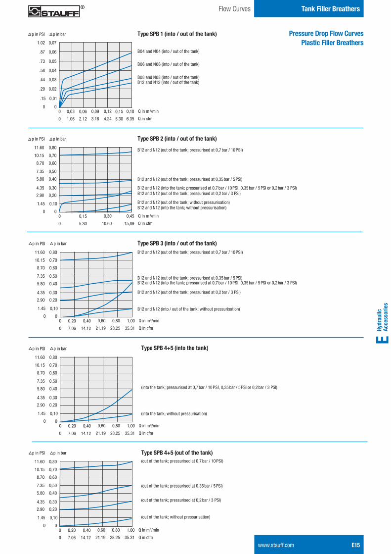
p in PSI Pressure Drop Flow Curves Plastic Filler Breathers
Type SPB 1 (into / out of the tank)
B04 and N04 (into / out of the tank)
B06 and N06 (into / out of the tank)
B08 and N08 (into / out of the tank)B12 and N12 (into / out of the tank)
0 0,15 0,30 0,45 Q in m3/min
0,70
0,60
0,50
0,40
0,30
0,20
0,10
0
p in bar
0 5.30 10.60 15,89 Q in cfm
10.15
08.70
07.35
05.80
04.35
02.90
01.45
0
p in PSI
0,8011.60
Type SPB 2 (into / out of the tank)
B12 and N12 (out of the tank; pressurised at 0,7 bar / 10 PSI)
B12 and N12 (out of the tank; pressurised at 0,35 bar / 5 PSI)
0 0,20 0,60 1,00 Q in m3/min
0,70
0,60
0,50
0,40
0,30
0,20
0,10
0
p in bar
0 7.06 21.19 35.31 Q in cfm
10.15
08.70
07.35
05.80
04.35
02.90
01.45
0
p in PSI
0,8011.60
0,40
14.12
0,80
28.25
Type SPB 3 (into / out of the tank)
0 0,20 0,60 1,00 Q in m3/min
0,70
0,60
0,50
0,40
0,30
0,20
0,10
0
p in bar
0 7.06 21.19 35.31 Q in cfm
10.15
08.70
07.35
05.80
04.35
02.90
01.45
0
p in PSI
0,8011.60
0,40
14.12
0,80
28.25
Type SPB 4+5 (into the tank)
0 0,20 0,60 1,00 Q in m3/min
0,70
0,60
0,50
0,40
0,30
0,20
0,10
0
p in bar
0 7.06 21.19 35.31 Q in cfm
10.15
08.70
07.35
05.80
04.35
02.90
01.45
0
p in PSI
0,8011.60
0,40
14.12
0,80
28.25
Type SPB 4+5 (out of the tank)
B12 and N12 (into the tank; pressurised at 0,7 bar / 10 PSI, 0,35 bar / 5 PSI or 0,2 bar / 3 PSI)B12 and N12 (out of the tank; pressurised at 0,2 bar / 3 PSI)
B12 and N12 (into the tank; without pressurisation)B12 and N12 (out of the tank; without pressurisation)
B12 and N12 (out of the tank; pressurised at 0,7 bar / 10 PSI)
B12 and N12 (out of the tank; pressurised at 0,35 bar / 5 PSI)B12 and N12 (into the tank; pressurised at 0,7 bar / 10 PSI, 0,35 bar / 5 PSI or 0,2 bar / 3 PSI)
B12 and N12 (into / out of the tank; without pressurisation)
B12 and N12 (out of the tank; pressurised at 0,2 bar / 3 PSI)
(out of the tank; pressurised at 0,7 bar / 10 PSI)
(out of the tank; pressurised at 0,35 bar / 5 PSI)
(out of the tank; without pressurisation)
(out of the tank; pressurised at 0,2 bar / 3 PSI)
(into the tank; pressurised at 0,7 bar / 10 PSI, 0,35 bar / 5 PSI or 0,2 bar / 3 PSI)
(into the tank; without pressurisation)
STAUFF ONE - Hydraulic Accessories - English.indd 15 23.11.2013 12:33:38
E16 www.stauff.com
Tank Filler Breathers
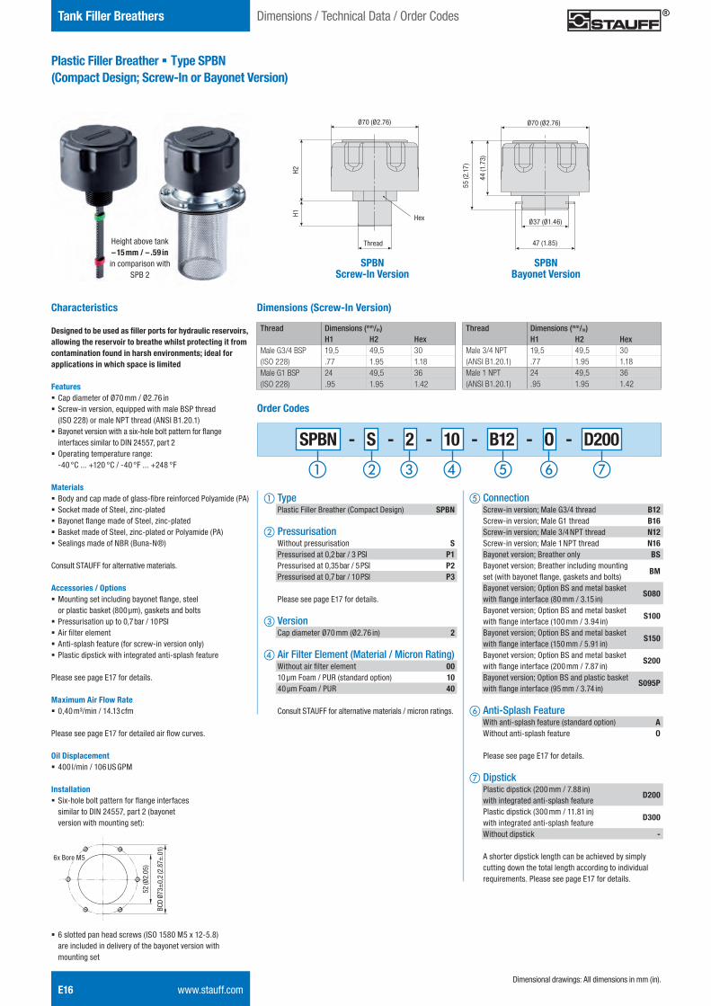
Plastic Filler Breather § Type SPBN(Compact Design; Screw-In or Bayonet Version)
Characteristics
Designed to be used as filler ports for hydraulic reservoirs, allowing the reservoir to breathe whilst protecting it from contamination found in harsh environments; ideal for applications in which space is limited
Features § Cap diameter of Ø70 mm / Ø2.76 in § Screw-in version, equipped with male BSP thread (ISO 228) or male NPT thread (ANSI B1.20.1)
§ Bayonet version with a six-hole bolt pattern for flange interfaces similar to DIN 24557, part 2
§ Operating temperature range: -40 °C ... +120 °C / -40 °F ... +248 °F
Materials § Body and cap made of glass-fibre reinforced Polyamide (PA) § Socket made of Steel, zinc-plated § Bayonet flange made of Steel, zinc-plated § Basket made of Steel, zinc-plated or Polyamide (PA) § Sealings made of NBR (Buna-N®)
Consult STAUFF for alternative materials.
Accessories / Options § Mounting set including bayonet flange, steel or plastic basket (800 μm), gaskets and bolts
§ Pressurisation up to 0,7 bar / 10 PSI § Air filter element § Anti-splash feature (for screw-in version only) § Plastic dipstick with integrated anti-splash feature
Please see page E17 for details.
Maximum Air Flow Rate § 0,40 m³/min / 14.13 cfm
Please see page E17 for detailed air flow curves.
Oil Displacement § 400 l/min / 106 US GPM
Installation § Six-hole bolt pattern for flange interfaces similar to DIN 24557, part 2 (bayonet version with mounting set):
§ 6 slotted pan head screws (ISO 1580 M5 x 12-5.8) are included in delivery of the bayonet version with mounting set
SPBN - S - 2 - 10 - B12 - O - D200
e Connection Screw-in version; Male G3/4 thread B12 Screw-in version; Male G1 thread B16 Screw-in version; Male 3/4 NPT thread N12 Screw-in version; Male 1 NPT thread N16 Bayonet version; Breather only BS Bayonet version; Breather including mounting set (with bayonet flange, gaskets and bolts)
BM
Bayonet version; Option BS and metal basket with flange interface (80 mm / 3.15 in)
S080
Bayonet version; Option BS and metal basket with flange interface (100 mm / 3.94 in)
S100
Bayonet version; Option BS and metal basket with flange interface (150 mm / 5.91 in)
S150
Bayonet version; Option BS and metal basket with flange interface (200 mm / 7.87 in)
S200
Bayonet version; Option BS and plastic basket with flange interface (95 mm / 3.74 in)
S095P
f Anti-Splash Feature With anti-splash feature (standard option) A Without anti-splash feature O
Please see page E17 for details.
g Dipstick Plastic dipstick (200 mm / 7.88 in) with integrated anti-splash feature
D200
Plastic dipstick (300 mm / 11.81 in) with integrated anti-splash feature
D300
Without dipstick -
A shorter dipstick length can be achieved by simply cutting down the total length according to individual requirements. Please see page E17 for details.
Order Codes
a Type Plastic Filler Breather (Compact Design) SPBN
b Pressurisation Without pressurisation S Pressurised at 0,2 bar / 3 PSI P1 Pressurised at 0,35 bar / 5 PSI P2 Pressurised at 0,7 bar / 10 PSI P3
Please see page E17 for details.
c Version Cap diameter Ø70 mm (Ø2.76 in) 2
d Air Filter Element (Material / Micron Rating) Without air filter element 00 10 μm Foam / PUR (standard option) 10 40 μm Foam / PUR 40
Consult STAUFF for alternative materials / micron ratings.
Dimensions (Screw-In Version)
Dimensional drawings: All dimensions in mm (in).
BCD
Ø73±
0,2
(2.8
7±.0
1)
52 (Ø
2.05
)
6x Bore M5
Ø70 (Ø2.76) Ø70 (Ø2.76)
SPBNScrew-In Version
SPBN Bayonet Version
44 (1
.73)
55 (2
.17)
47 (1.85)
Ø37 (Ø1.46)
Thread
Hex
H2H1
Thread Dimensions (mm/in)H1 H2 Hex
Male G3/4 BSP(ISO 228)
19,5 49,5 30.77 1.95 1.18
Male G1 BSP(ISO 228)
24 49,5 36.95 1.95 1.42
Thread Dimensions (mm/in)H1 H2 Hex
Male 3/4 NPT(ANSI B1.20.1)
19,5 49,5 30.77 1.95 1.18
Male 1 NPT(ANSI B1.20.1)
24 49,5 36.95 1.95 1.42
Dimensions / Technical Data / Order Codes
Height above tank– 15 mm / – .59 in in comparison with
SPB 2
STAUFF ONE - Hydraulic Accessories - English.indd 16 23.11.2013 12:33:40
Hydr
aulic
Ac
cess
orie
sE
Tank Filler BreathersAccessories / Options / Flow Curves
www.stauff.com E17
Pressure Drop Flow Curves Plastic Filler Breathers
Type SPBN (into the tank)
0 0,15 0,30 0,45 Q in m3/min
0,70
0,60
0,50
0,40
0,30
0,20
0,10
0
p in bar
0 5.30 10.60 15,89 Q in cfm
10.15
08.70
07.35
05.80
04.35
02.90
01.45
0
p in PSI
0,8011.60
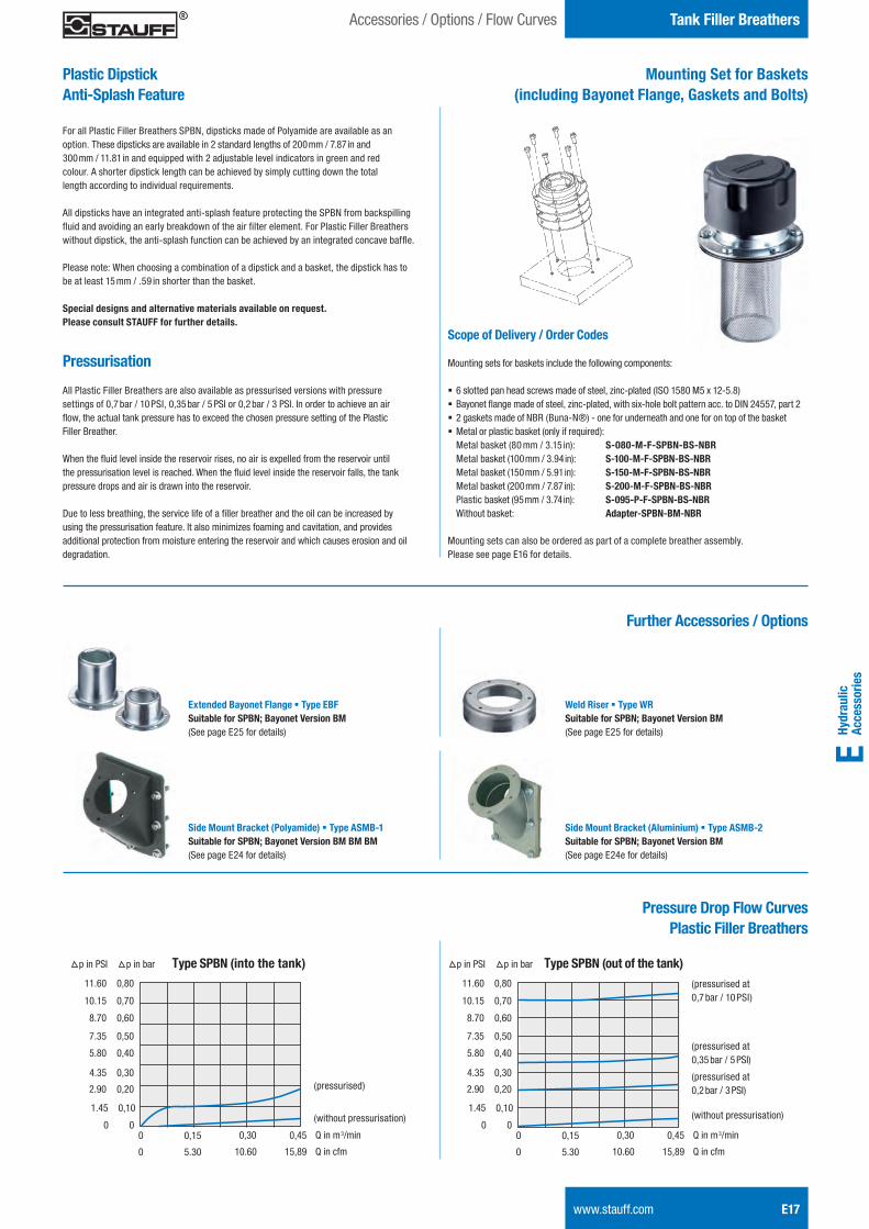
Type SPBN (out of the tank)(pressurised at 0,7 bar / 10 PSI)
(pressurised at 0,35 bar / 5 PSI)
(without pressurisation)
(pressurised at 0,2 bar / 3 PSI)(pressurised)
(without pressurisation)
Weld Riser § Type WRSuitable for SPBN; Bayonet Version BM (See page E25 for details)
Side Mount Bracket (Polyamide) § Type ASMB-1Suitable for SPBN; Bayonet Version BM BM BM (See page E24 for details)
Side Mount Bracket (Aluminium) § Type ASMB-2Suitable for SPBN; Bayonet Version BM (See page E24e for details)
Further Accessories / Options
Extended Bayonet Flange § Type EBFSuitable for SPBN; Bayonet Version BM (See page E25 for details)
Mounting Set for Baskets(including Bayonet Flange, Gaskets and Bolts)
Scope of Delivery / Order Codes
Mounting sets for baskets include the following components:
§ 6 slotted pan head screws made of steel, zinc-plated (ISO 1580 M5 x 12-5.8) § Bayonet flange made of steel, zinc-plated, with six-hole bolt pattern acc. to DIN 24557, part 2 § 2 gaskets made of NBR (Buna-N®) - one for underneath and one for on top of the basket § Metal or plastic basket (only if required): Metal basket (80 mm / 3.15 in): S-080-M-F-SPBN-BS-NBR Metal basket (100 mm / 3.94 in): S-100-M-F-SPBN-BS-NBR Metal basket (150 mm / 5.91 in): S-150-M-F-SPBN-BS-NBR Metal basket (200 mm / 7.87 in): S-200-M-F-SPBN-BS-NBR Plastic basket (95 mm / 3.74 in): S-095-P-F-SPBN-BS-NBR Without basket: Adapter-SPBN-BM-NBR
Mounting sets can also be ordered as part of a complete breather assembly. Please see page E16 for details.
Plastic Dipstick Anti-Splash Feature
For all Plastic Filler Breathers SPBN, dipsticks made of Polyamide are available as anoption. These dipsticks are available in 2 standard lengths of 200 mm / 7.87 in and 300 mm / 11.81 in and equipped with 2 adjustable level indicators in green and red colour.
A shorter dipstick length can be achieved by simply cutting down the total
length according to individual requirements.
All dipsticks have an integrated anti-splash feature protecting the SPBN from backspilling fluid and avoiding an early breakdown of the air filter element. For Plastic Filler Breathers without dipstick, the anti-splash function can be achieved by an integrated concave baffle.
Please note: When choosing a combination of a dipstick and a basket, the dipstick has to be at least 15 mm / .59 in shorter than the basket.
Special designs and alternative materials available on request. Please consult STAUFF for further details.
Pressurisation
All Plastic Filler Breathers are also available as pressurised versions with pressure settings of 0,7 bar / 10 PSI, 0,35 bar / 5 PSI or 0,2 bar / 3 PSI. In order to achieve an air flow, the actual tank pressure has to exceed the chosen pressure setting of the Plastic Filler Breather.
When the fluid level inside the reservoir rises, no air is expelled from the reservoir until the pressurisation level is reached. When the fluid level inside the reservoir falls, the tank pressure drops and air is drawn into the reservoir.
Due to less breathing, the service life of a filler breather and the oil can be increased by using the pressurisation feature. It also minimizes foaming and cavitation, and provides additional protection from moisture entering the reservoir and which causes erosion and oil degradation.
0 0,15 0,30 0,45 Q in m3/min
0,70
0,60
0,50
0,40
0,30
0,20
0,10
0
p in bar
0 5.30 10.60 15,89 Q in cfm
10.15
08.70
07.35
05.80
04.35
02.90
01.45
0
p in PSI
0,8011.60
STAUFF ONE - Hydraulic Accessories - English.indd 17 23.11.2013 12:33:41
E18 www.stauff.com
Tank Filler Breathers
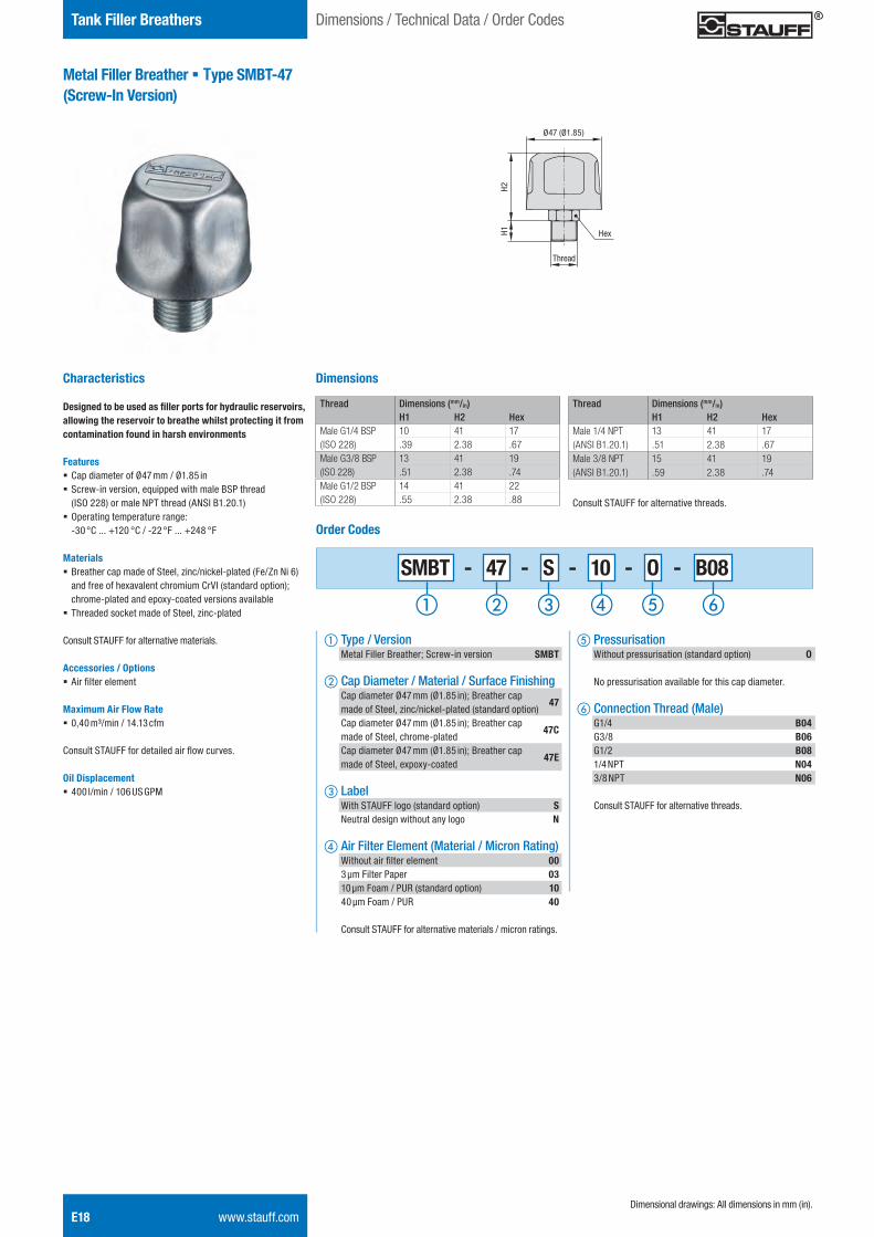
Metal Filler Breather § Type SMBT-47(Screw-In Version)
Characteristics
Designed to be used as filler ports for hydraulic reservoirs, allowing the reservoir to breathe whilst protecting it from contamination found in harsh environments
Features § Cap diameter of Ø47 mm / Ø1.85 in § Screw-in version, equipped with male BSP thread (ISO 228) or male NPT thread (ANSI B1.20.1)
§ Operating temperature range: -30 °C ... +120 °C / -22 °F ... +248 °F
Materials § Breather cap made of Steel, zinc/nickel-plated (Fe/Zn Ni 6) and free of hexavalent chromium CrVI (standard option); chrome-plated and epoxy-coated versions available
§ Threaded socket made of Steel, zinc-plated
Consult STAUFF for alternative materials.
Accessories / Options § Air filter element
Maximum Air Flow Rate § 0,40 m³/min / 14.13 cfm
Consult STAUFF for detailed air flow curves.
Oil Displacement § 400 l/min / 106 US GPM
Hex
SMBT - 47 - S - 10 - O - B08
e Pressurisation Without pressurisation (standard option) O
No pressurisation available for this cap diameter.
f Connection Thread (Male) G1/4 B04 G3/8 B06 G1/2 B08 1/4 NPT N04 3/8 NPT N06
Consult STAUFF for alternative threads.
Order Codes
a Type / Version Metal Filler Breather; Screw-in version SMBT
b Cap Diameter / Material / Surface Finishing Cap diameter Ø47 mm (Ø1.85 in); Breather cap made of Steel, zinc/nickel-plated (standard option)
47 Cap diameter Ø47 mm (Ø1.85 in); Breather cap made of Steel, chrome-plated
47C
Cap diameter Ø47 mm (Ø1.85 in); Breather cap made of Steel, expoxy-coated
47E
c Label With STAUFF logo (standard option) S Neutral design without any logo N
d Air Filter Element (Material / Micron Rating) Without air filter element 00 3 μm Filter Paper 03 10 μm Foam / PUR (standard option) 10 40 μm Foam / PUR 40
Consult STAUFF for alternative materials / micron ratings.
Dimensions
Thread Dimensions (mm/in)H1 H2 Hex
Male G1/4 BSP(ISO 228)
10 41 17.39 2.38 .67
Male G3/8 BSP(ISO 228)
13 41 19.51 2.38 .74
Male G1/2 BSP(ISO 228)
14 41 22.55 2.38 .88
Thread Dimensions (mm/in)H1 H2 Hex
Male 1/4 NPT(ANSI B1.20.1)
13 41 17.51 2.38 .67
Male 3/8 NPT(ANSI B1.20.1)
15 41 19.59 2.38 .74
Dimensional drawings: All dimensions in mm (in).
Thread
Ø47 (Ø1.85)
H2H1
Consult STAUFF for alternative threads.
Dimensions / Technical Data / Order Codes
STAUFF ONE - Hydraulic Accessories - English.indd 18 23.11.2013 12:33:42
Hydr
aulic
Ac
cess
orie
sE
Tank Filler Breathers
www.stauff.com E19
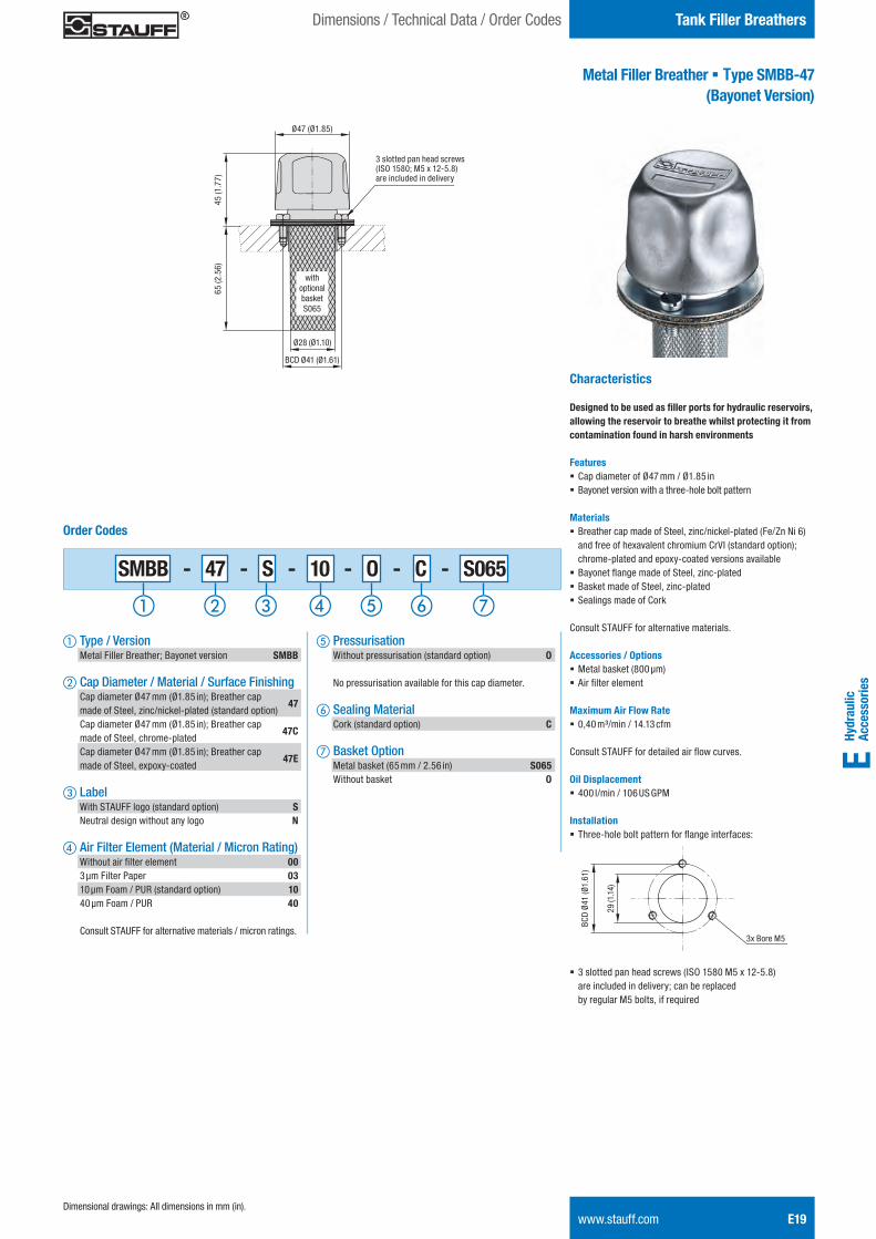
Metal Filler Breather § Type SMBB-47 (Bayonet Version)
Characteristics
Designed to be used as filler ports for hydraulic reservoirs, allowing the reservoir to breathe whilst protecting it from contamination found in harsh environments
Features § Cap diameter of Ø47 mm / Ø1.85 in § Bayonet version with a three-hole bolt pattern
Materials § Breather cap made of Steel, zinc/nickel-plated (Fe/Zn Ni 6) and free of hexavalent chromium CrVI (standard option); chrome-plated and epoxy-coated versions available
§ Bayonet flange made of Steel, zinc-plated § Basket made of Steel, zinc-plated § Sealings made of Cork
Consult STAUFF for alternative materials.
Accessories / Options § Metal basket (800 μm) § Air filter element
Maximum Air Flow Rate § 0,40 m³/min / 14.13 cfm
Consult STAUFF for detailed air flow curves.
Oil Displacement § 400 l/min / 106 US GPM
Installation § Three-hole bolt pattern for flange interfaces:
§ 3 slotted pan head screws (ISO 1580 M5 x 12-5.8) are included in delivery; can be replaced by regular M5 bolts, if required
e Pressurisation Without pressurisation (standard option) O
No pressurisation available for this cap diameter.
f Sealing Material Cork (standard option) C
g Basket Option Metal basket (65 mm / 2.56 in) S065 Without basket O
Order Codes
a Type / Version Metal Filler Breather; Bayonet version SMBB
b Cap Diameter / Material / Surface Finishing Cap diameter Ø47 mm (Ø1.85 in); Breather cap made of Steel, zinc/nickel-plated (standard option)
47 Cap diameter Ø47 mm (Ø1.85 in); Breather cap made of Steel, chrome-plated
47C
Cap diameter Ø47 mm (Ø1.85 in); Breather cap made of Steel, expoxy-coated
47E
c Label With STAUFF logo (standard option) S Neutral design without any logo N
d Air Filter Element (Material / Micron Rating) Without air filter element 00 3 μm Filter Paper 03 10 μm Foam / PUR (standard option) 10 40 μm Foam / PUR 40
Consult STAUFF for alternative materials / micron ratings.
Dimensional drawings: All dimensions in mm (in).
SMBB - 47 - S - 10 - O - C - S065BC
D Ø
41 (Ø
1.61
)
29 (1
.14)
3x Bore M5
Ø47 (Ø1.85)
45 (1
.77)
65 (2
.56)
BCD Ø41 (Ø1.61)
Ø28 (Ø1.10)
3 slotted pan head screws (ISO 1580; M5 x 12-5.8)are included in delivery
with optional basket S065
Dimensions / Technical Data / Order Codes
STAUFF ONE - Hydraulic Accessories - English.indd 19 23.11.2013 12:33:44
E20 www.stauff.com
Tank Filler Breathers
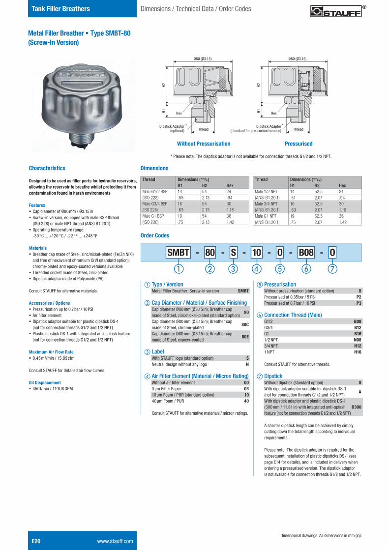
Metal Filler Breather § Type SMBT-80(Screw-In Version)
Characteristics
Designed to be used as filler ports for hydraulic reservoirs, allowing the reservoir to breathe whilst protecting it from contamination found in harsh environments
Features § Cap diameter of Ø80 mm / Ø3.15 in § Screw-in version, equipped with male BSP thread (ISO 228) or male NPT thread (ANSI B1.20.1)
§ Operating temperature range: -30 °C ... +120 °C / -22 °F ... +248 °F
Materials § Breather cap made of Steel, zinc/nickel-plated (Fe/Zn Ni 6) and free of hexavalent chromium CrVI (standard option); chrome-plated and epoxy-coated versions available
§ Threaded socket made of Steel, zinc-plated § Dipstick adaptor made of Polyamide (PA)
Consult STAUFF for alternative materials.
Accessories / Options § Pressurisation up to 0,7 bar / 10 PSI § Air filter element § Dipstick adaptor suitable for plastic dipstick DS-1 (not for connection threads G1/2 and 1/2 NPT)
§ Plastic dipstick DS-1 with integrated anti-splash feature (not for connection threads G1/2 and 1/2 NPT)
Maximum Air Flow Rate § 0,45 m³/min / 15.89 cfm
Consult STAUFF for detailed air flow curves.
Oil Displacement § 450 l/min / 119 US GPM
SMBT - 80 - S - 10 - O - B08 - O
e Pressurisation Without pressurisation (standard option) O Pressurised at 0,35 bar / 5 PSI P2 Pressurised at 0,7 bar / 10 PSI P3
f Connection Thread (Male) G1/2 B08 G3/4 B12 G1 B16 1/2 NPT N08 3/4 NPT N12 1 NPT N16
Consult STAUFF for alternative threads.
g Dipstick Without dipstick (standard option) O With dipstick adaptor suitable for dipstick DS-1 (not for connection threads G1/2 and 1/2 NPT)
A
With dipstick adaptor and plastic dipstick DS-1 (300 mm / 11.81 in) with integrated anti-splash D300 feature (not for connection threads G1/2 and 1/2 NPT)
A shorter dipstick length can be achieved by simply cutting down the total length according to individual requirements.
Please note: The dipstick adaptor is required for the subsequent installation of plastic dipsticks DS-1 (see page E14 for details), and is included in delivery when ordering a pressurised version. The dipstick adaptor is not available for connection threads G1/2 and 1/2 NPT.
Order Codes
a Type / Version Metal Filler Breather; Screw-in version SMBT
b Cap Diameter / Material / Surface Finishing Cap diameter Ø80 mm (Ø3.15 in); Breather cap made of Steel, zinc/nickel-plated (standard option)
80 Cap diameter Ø80 mm (Ø3.15 in); Breather cap made of Steel, chrome-plated
80C
Cap diameter Ø80 mm (Ø3.15 in); Breather cap made of Steel, expoxy-coated
80E
c Label With STAUFF logo (standard option) S Neutral design without any logo N
d Air Filter Element (Material / Micron Rating) Without air filter element 00 3 μm Filter Paper 03 10 μm Foam / PUR (standard option) 10 40 μm Foam / PUR 40
Consult STAUFF for alternative materials / micron ratings.
Dimensions
Thread Dimensions (mm/in)H1 H2 Hex
Male G1/2 BSP(ISO 228)
14 54 24.55 2.13 .94
Male G3/4 BSP(ISO 228)
16 54 30.63 2.13 1.18
Male G1 BSP(ISO 228)
19 54 36.75 2.13 1.42
Thread Dimensions (mm/in)H1 H2 Hex
Male 1/2 NPT(ANSI B1.20.1)
14 52,5 24.51 2.07 .94
Male 3/4 NPT(ANSI B1.20.1)
16 52,5 30.59 2.07 1.18
Male G1 NPT(ANSI B1.20.1)
19 52,5 36.75 2.07 1.42
Dimensional drawings: All dimensions in mm (in).
Dimensions / Technical Data / Order Codes
Without Pressurisation Pressurised
Hex
Ø80 (Ø3.15)
Thread
H2H1 Hex
Ø80 (Ø3.15)
Thread
H2H1
Dipstick Adaptor (optional)
Dipstick Adaptor(standard for pressurised version)
* Please note: The disptick adaptor is not available for connection threads G1/2 and 1/2 NPT.
* *
STAUFF ONE - Hydraulic Accessories - English.indd 20 23.11.2013 12:33:45
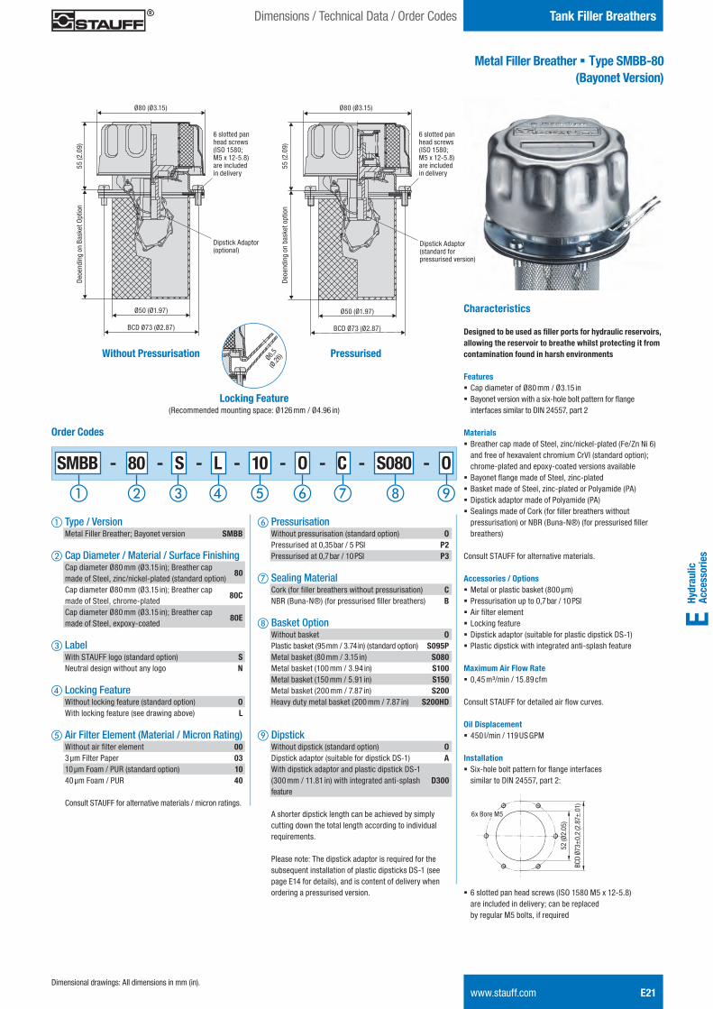
Hydr
aulic
Ac
cess
orie
sE
Tank Filler Breathers
www.stauff.com E21
Metal Filler Breather § Type SMBB-80 (Bayonet Version)
Characteristics
Designed to be used as filler ports for hydraulic reservoirs, allowing the reservoir to breathe whilst protecting it from contamination found in harsh environments
Features § Cap diameter of Ø80 mm / Ø3.15 in § Bayonet version with a six-hole bolt pattern for flange interfaces similar to DIN 24557, part 2
Materials § Breather cap made of Steel, zinc/nickel-plated (Fe/Zn Ni 6) and free of hexavalent chromium CrVI (standard option); chrome-plated and epoxy-coated versions available
§ Bayonet flange made of Steel, zinc-plated § Basket made of Steel, zinc-plated or Polyamide (PA) § Dipstick adaptor made of Polyamide (PA) § Sealings made of Cork (for filler breathers without pressurisation) or NBR (Buna-N®) (for pressurised filler breathers)
Consult STAUFF for alternative materials.
Accessories / Options § Metal or plastic basket (800 μm) § Pressurisation up to 0,7 bar / 10 PSI § Air filter element § Locking feature § Dipstick adaptor (suitable for plastic dipstick DS-1) § Plastic dipstick with integrated anti-splash feature
Maximum Air Flow Rate § 0,45 m³/min / 15.89 cfm
Consult STAUFF for detailed air flow curves.
Oil Displacement § 450 l/min / 119 US GPM
Installation § Six-hole bolt pattern for flange interfaces similar to DIN 24557, part 2:
§ 6 slotted pan head screws (ISO 1580 M5 x 12-5.8) are included in delivery; can be replaced by regular M5 bolts, if required
f Pressurisation Without pressurisation (standard option) O Pressurised at 0,35 bar / 5 PSI P2 Pressurised at 0,7 bar / 10 PSI P3
g Sealing Material Cork (for filler breathers without pressurisation) C NBR (Buna-N®) (for pressurised filler breathers) B
h Basket Option Without basket O Plastic basket (95 mm / 3.74 in) (standard option) S095P Metal basket (80 mm / 3.15 in) S080 Metal basket (100 mm / 3.94 in) S100 Metal basket (150 mm / 5.91 in) S150 Metal basket (200 mm / 7.87 in) S200 Heavy duty metal basket (200 mm / 7.87 in) S200HD
i Dipstick Without dipstick (standard option) O Dipstick adaptor (suitable for dipstick DS-1) A With dipstick adaptor and plastic dipstick DS-1 (300 mm / 11.81 in) with integrated anti-splash D300 feature
A shorter dipstick length can be achieved by simply cutting down the total length according to individual requirements.
Please note: The dipstick adaptor is required for the subsequent installation of plastic dipsticks DS-1 (see page E14 for details), and is content of delivery when ordering a pressurised version.
Order Codes
a Type / Version Metal Filler Breather; Bayonet version SMBB
b Cap Diameter / Material / Surface Finishing Cap diameter Ø80 mm (Ø3.15 in); Breather cap made of Steel, zinc/nickel-plated (standard option)
80 Cap diameter Ø80 mm (Ø3.15 in); Breather cap made of Steel, chrome-plated
80C
Cap diameter Ø80 mm (Ø3.15 in); Breather cap made of Steel, expoxy-coated
80E
c Label With STAUFF logo (standard option) S Neutral design without any logo N
d Locking Feature Without locking feature (standard option) O With locking feature (see drawing above) L
e Air Filter Element (Material / Micron Rating) Without air filter element 00 3 μm Filter Paper 03 10 μm Foam / PUR (standard option) 10 40 μm Foam / PUR 40
Consult STAUFF for alternative materials / micron ratings.
Dimensional drawings: All dimensions in mm (in).
Dimensions / Technical Data / Order Codes
Without Pressurisation Pressurised
SMBB - 80 - S - L - 10 - O - C - S080 - O
Locking Feature (Recommended mounting space: Ø126 mm / Ø4.96 in)
Ø6,5
(Ø.26
)
BCD
Ø73±
0,2
(2.8
7±.0
1)
52 (Ø
2.05
)
6x Bore M5
Ø80 (Ø3.15)
55 (2
.09)
Deo
endi
ng o
n Ba
sket
Opt
ion
Ø80 (Ø3.15)
55 (2
.09)
Deo
endi
ng o
n ba
sket
opt
ion
Ø50 (Ø1.97)
BCD Ø73 (Ø2.87)
Ø50 (Ø1.97)
BCD Ø73 (Ø2.87)
6 slotted pan head screws (ISO 1580; M5 x 12-5.8)are included in delivery
6 slotted pan head screws (ISO 1580; M5 x 12-5.8)are included in delivery
Dipstick Adaptor (optional)
Dipstick Adaptor (standard for pressurised version)
STAUFF ONE - Hydraulic Accessories - English.indd 21 23.11.2013 12:33:47
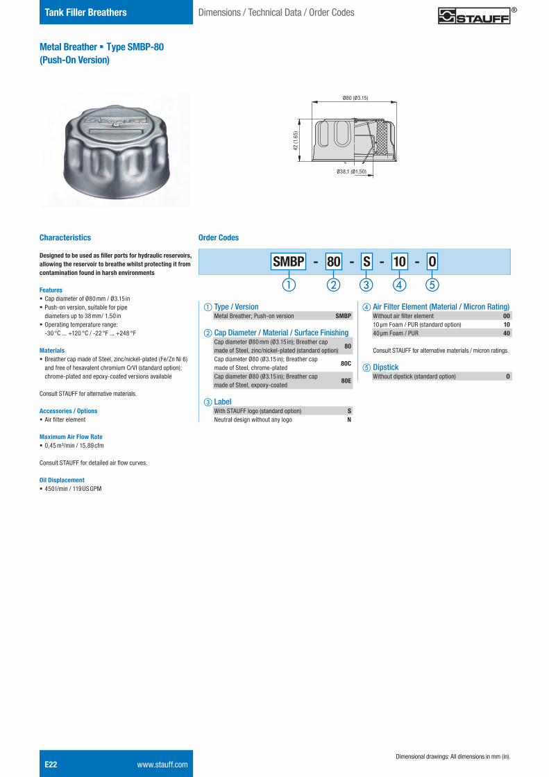
E22 www.stauff.com
Tank Filler Breathers
Metal Breather § Type SMBP-80(Push-On Version)
Characteristics
Designed to be used as filler ports for hydraulic reservoirs, allowing the reservoir to breathe whilst protecting it from contamination found in harsh environments
Features § Cap diameter of Ø80 mm / Ø3.15 in § Push-on version, suitable for pipe diameters up to 38 mm/ 1.50 in
§ Operating temperature range: -30 °C ... +120 °C / -22 °F ... +248 °F
Materials § Breather cap made of Steel, zinc/nickel-plated (Fe/Zn Ni 6) and free of hexavalent chromium CrVI (standard option); chrome-plated and epoxy-coated versions available
Consult STAUFF for alternative materials.
Accessories / Options § Air filter element
Maximum Air Flow Rate § 0,45 m³/min / 15.89 cfm
Consult STAUFF for detailed air flow curves.
Oil Displacement § 450 l/min / 119 US GPM
SMBP - 80 - S - 10 - O
d Air Filter Element (Material / Micron Rating) Without air filter element 00 10 μm Foam / PUR (standard option) 10 40 μm Foam / PUR 40
Consult STAUFF for alternative materials / micron ratings.
e Dipstick Without dipstick (standard option) O
Order Codes
a Type / Version Metal Breather; Push-on version SMBP
b Cap Diameter / Material / Surface Finishing Cap diameter Ø80 mm (Ø3.15 in); Breather cap made of Steel, zinc/nickel-plated (standard option)
80 Cap diameter Ø80 (Ø3.15 in); Breather cap made of Steel, chrome-plated
80C
Cap diameter Ø80 (Ø3.15 in); Breather cap made of Steel, expoxy-coated
80E
c Label With STAUFF logo (standard option) S Neutral design without any logo N
Dimensional drawings: All dimensions in mm (in).
Dimensions / Technical Data / Order Codes
Ø38,1 (Ø1.50)
Ø80 (Ø3.15)
42 (1
.65)
STAUFF ONE - Hydraulic Accessories - English.indd 22 23.11.2013 12:33:48
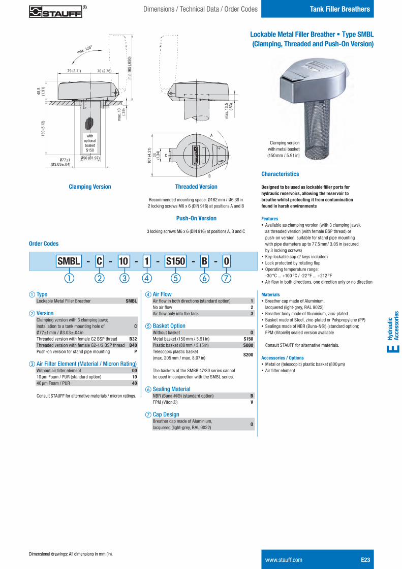
Hydr
aulic
Ac
cess
orie
sE
www.stauff.com E23Dimensional drawings: All dimensions in mm (in).
Lockable Metal Filler Breather § Type SMBL(Clamping, Threaded and Push-On Version)
Characteristics
Designed to be used as lockable filler ports for hydraulic reservoirs, allowing the reservoir to breathe whilst protecting it from contamination found in harsh environments
Features § Available as clamping version (with 3 clamping jaws), as threaded version (with female BSP thread) or push-on version, suitable for stand pipe mounting with pipe diameters up to 77,5 mm/ 3.05 in (secured by 3 locking screws)
§ Key-lockable cap (2 keys included) § Lock protected by rotating flap § Operating temperature range: -30 °C ... +100 °C / -22 °F ... +212 °F
§ Air flow in both directions, one direction only or no direction
Materials § Breather cap made of Aluminium, lacquered (light-grey, RAL 9022)
§ Breather body made of Aluminium, zinc-plated § Basket made of Steel, zinc-plated or Polypropylene (PP) § Sealings made of NBR (Buna-N®) (standard option); FPM (Viton®) sealed version available Consult STAUFF for alternative materials.
Accessories / Options § Metal or (telescopic) plastic basket (800 μm) § Air filter element
Dimensions / Technical Data / Order Codes
d Air Flow Air flow in both directions (standard option) 1 No air flow 2 Air flow only into the tank 3
e Basket Option Without basket O Metal basket (150 mm / 5.91 in) S150 Plastic basket (80 mm / 3.15 in) S080 Telescopic plastic basket (max. 205 mm / max. 8.07 in)
S200
The baskets of the SMBB 47/80 series cannot be used in conjunction with the SMBL series.
f Sealing Material NBR (Buna-N®) (standard option) B FPM (Viton®) V
g Cap Design Breather cap made of Aluminium, lacquered (light-grey, RAL 9022)
O
Order Codes
a Type Lockable Metal Filler Breather SMBL
b Version Clamping version with 3 clamping jaws; Installation to a tank mounting hole of C Ø77±1 mm / Ø3.03±.04 in Threaded version with female G2 BSP thread B32 Threaded version with female G2-1/2 BSP thread B40 Push-on version for stand pipe mounting P
c Air Filter Element (Material / Micron Rating) Without air filter element 00 10 μm Foam / PUR (standard option) 10 40 μm Foam / PUR 40
Consult STAUFF for alternative materials / micron ratings.
SMBL - C - 10 - 1 - S150 - B - 0
Clamping version with metal basket (150 mm / 5.91 in)
Clamping Version
with optional basket S150
max. 125°
79 (3.11) 70 (2.76)
48,5
(1
.91)
130
(5.1
2)
Ø50 (Ø1.97)Ø77±1 (Ø3.03±.04)
min
165
(.65
0)
max
. 10
(.39)
max
. 13,
5(.5
3)
Threaded Version
A
B
C
107
(4.2
1)34
(1.3
4)
Recommended mounting space: Ø162 mm / Ø6.38 in2 locking screws M6 x 6 (DIN 916) at positions A and B
3 locking screws M6 x 6 (DIN 916) at positions A, B and C
Push-On Version
Tank Filler Breathers
STAUFF ONE - Hydraulic Accessories - English.indd 23 23.11.2013 12:33:50
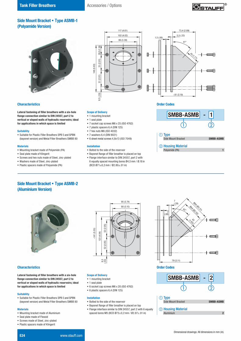
E24 www.stauff.com
Tank Filler Breathers
Side Mount Bracket § Type ASMB-1(Polyamide Version)
Characteristics
Lateral fastening of filler breathers with a six-hole flange connection similar to DIN 24557, part 2 to vertical or sloped walls of hydraulic reservoirs; ideal for applications in which space is limited
Suitability § Suitable for Plastic Filler Breathers SPB 5 and SPBN (bayonet version) and Metal Filler Breathers SMBB 80
Materials § Mounting bracket made of Polyamide (PA) § Seal plate made of Klingerit § Screws and hex nuts made of Steel, zinc-plated § Washers made of Steel, zinc-plated § Plastic spacers made of Polyamide (PA)
Dimensional drawings: All dimensions in mm (in).
Accessories / Options
73,4 (2.89)
5,5 (.22)1,5 (.06)
41°
45 (1.77)
~81 (3.19)
117 (4.61)
102 (4.02)
86 (3.38)
148
(5.8
3)
51 (2
.01)
51 (2
.01)
29,5
(1.1
6)8,
5 (.3
3)
Scope of Delivery § 1 mounting bracket § 1 seal plate § 7 socket cap screws M6 x 25 (ISO 4762) § 7 plastic spacers 6,4 (DIN 125) § 7 hex nuts M6 (ISO 4032) § 7 washers 6,4 (DIN 9021) § 6 sheet metal screws 4,8x13 (ISO 7049)
Installation § Bolted to the side of the reservoir § Bayonet flange of filler breather is placed on top § Flange interface similar to DIN 24557, part 2 with 6 equally spaced mounting bores Ø4,5 mm / Ø.18 in (BCD Ø71±0,2 mm / Ø2.80±.01 in)
95 (3.74)
80 (3.15)
~141
(5.5
5)
123
(4.8
4)
52 (2
.05)
52 (2
.05)
8,5
(.33) 79 (3.11)
7(.28)
2(.08)
Ø84 (Ø3.31)
Ø64 (Ø2.52)
42 (1.65)
45°
Scope of Delivery § 1 mounting bracket § 1 seal plate § 6 socket cap screws M6 x 20 (ISO 4762) § 6 plastic spacers 6,4 (DIN 125)
Installation § Bolted to the side of the reservoir § Bayonet flange of filler breather is placed on top § Flange interface similar to DIN 24557, part 2 with 6 equally spaced bores M5 (BCD Ø73±0,2 mm / Ø2.87±.01 in)
Side Mount Bracket § Type ASMB-2(Aluminium Version)
Characteristics
Lateral fastening of filler breathers with a six-hole flange connection similar to DIN 24557, part 2 to vertical or sloped walls of hydraulic reservoirs; ideal for applications in which space is limited
Suitability § Suitable for Plastic Filler Breathers SPB 5 and SPBN (bayonet version) and Metal Filler Breathers SMBB 80
Materials § Mounting bracket made of Aluminium § Seal plate made of Flexoid § Screws made of Steel, zinc-plated § Plastic spacers made of Klingerit
Order Codes
SMBB-ASMB - 1
a Type Side Mount Bracket SMBB-ASMB
b Housing Material Polyamide (PA) 1
Order Codes
SMBB-ASMB - 2
a Type Side Mount Bracket SMBB-ASMB
b Housing Material Aluminium 2
STAUFF ONE - Hydraulic Accessories - English.indd 24 23.11.2013 12:33:51
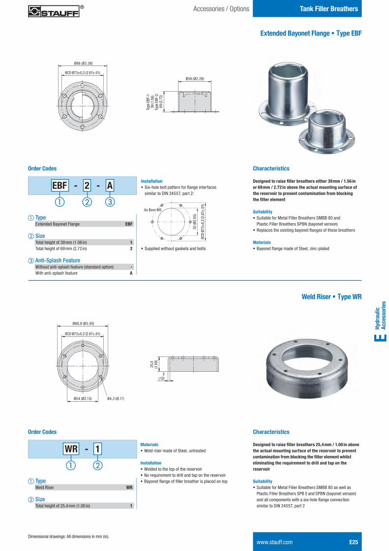
Hydr
aulic
Ac
cess
orie
sE
Tank Filler BreathersAccessories / Options
www.stauff.com E25
Extended Bayonet Flange § Type EBF
Characteristics
Designed to raise filler breathers either 39 mm / 1.56 in or 69 mm / 2.72 in above the actual mounting surface of the reservoir to prevent contamination from blocking the filter element
Suitability § Suitable for Metal Filler Breathers SMBB 80 and Plastic Filler Breathers SPBN (bayonet version)
§ Replaces the existing bayonet flanges of these breathers
Materials § Bayonet flange made of Steel, zinc-plated
Ø86 (Ø3.38)
BCD Ø73±0,2 (2.87±.01)
Ø58 (Ø2.28)
Type
EBF
-1:
39 (1
.56)
Type
EBF
-2:
69
(2.7
2)
Order Codes
a Type Extended Bayonet Flange EBF
b Size Total height of 39 mm (1.56 in) 1 Total height of 69 mm (2.72 in) 2
c Anti-Splash Feature Without anti-splash feature (standard option) - With anti-splash feature A
Dimensional drawings: All dimensions in mm (in).
Installation § Six-hole bolt pattern for flange interfaces similar to DIN 24557, part 2:
§ Supplied without gaskets and bolts
BCD
Ø73±
0,2
(2.8
7±.0
1)
52 (Ø
2.05
)
6x Bore M5
Weld Riser § Type WR
Characteristics
Designed to raise filler breathers 25,4 mm / 1.00 in above the actual mounting surface of the reservoir to prevent contamination from blocking the filter element whilst eliminating the requirement to drill and tap on the reservoir
Suitability § Suitable for Metal Filler Breathers SMBB 80 as well as Plastic Filler Breathers SPB 5 and SPBN (bayonet version) and all components with a six-hole flange connection similar to DIN 24557, part 2
Ø88,9 (Ø3.50)
BCD Ø73±0,2 (2.87±.01)
25,4
(1.0
0)
Order Codes
WR - 1
a Type Weld Riser WR
b Size Total height of 25,4 mm (1.00 in) 1
Materials § Weld riser made of Steel, untreated
Installation § Welded to the top of the reservoir § No requirement to drill and tap on the reservoir § Bayonet flange of filler breather is placed on top
Ø4,3 (Ø.17)Ø54 (Ø2.13)
3(.12)
EBF - 2 - A
STAUFF ONE - Hydraulic Accessories - English.indd 25 23.11.2013 12:33:52
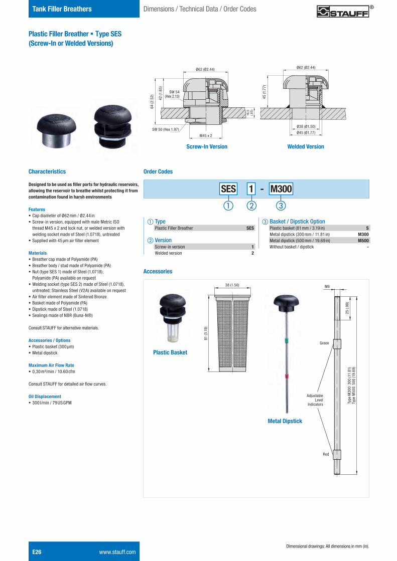
E26 www.stauff.com
Tank Filler Breathers
Plastic Filler Breather § Type SES (Screw-In or Welded Versions)
Characteristics
Designed to be used as filler ports for hydraulic reservoirs, allowing the reservoir to breathe whilst protecting it from contamination found in harsh environments
Features § Cap diameter of Ø62 mm / Ø2.44 in § Screw-in version, equipped with male Metric ISO thread M45 x 2 and lock nut, or welded version with welding socket made of Steel (1.0718), untreated
§ Supplied with 45 μm air filter element Materials § Breather cap made of Polyamide (PA) § Breather body / stud made of Polyamide (PA) § Nut (type SES 1) made of Steel (1.0718); Polyamide (PA) available on request
§ Welding socket (type SES 2) made of Steel (1.0718), untreated; Stainless Steel (V2A) available on request
§ Air filter element made of Sintered Bronze § Basket made of Polyamide (PA) § Dipstick made of Steel (1.0718) § Sealings made of NBR (Buna-N®)
Consult STAUFF for alternative materials.
Accessories / Options § Plastic basket (300 μm) § Metal dipstick
Maximum Air Flow Rate § 0,30 m³/min / 10.60 cfm
Consult STAUFF for detailed air flow curves.
Oil Displacement § 300 l/min / 79 US GPM
SES 1 - M300
c Basket / Dipstick Option Plastic basket (81 mm / 3.19 in) S Metal dipstick (300 mm / 11.81 in) M300 Metal dipstick (500 mm / 19.69 in) M500 Without basket / dipstick -
Order Codes
a Type Plastic Filler Breather SES
b Version Screw-in version 1 Welded version 2
Dimensional drawings: All dimensions in mm (in).
Dimensions / Technical Data / Order Codes
Screw-In Version Welded Version
Ø62 (Ø2.44)
Ø38 (Ø1.50)
Ø45 (Ø1.77)
45 (1
.77)
M45 x 2
SW 50 (Hex 1.97)
SW 54 (Hex 2.13)
Ø62 (Ø2.44)
64 (2
.52)
42 (1
.65)
Accessories
81 (3
.19)
38 (1.50)
adjustable
green
red
300
/500
25
M6M6
Green
Red
Adjustable Level
Indicators Type
M30
0: 3
00 (1
1.81
)Ty
pe M
500:
500
(19.
69)
25 (.
98)
Plastic Basket
Metal Dipstick
16,5
(.6
5)
STAUFF ONE - Hydraulic Accessories - English.indd 26 23.11.2013 12:33:54
Hydr
aulic
Ac
cess
orie
sE
Notes
www.stauff.com E27
STAUFF ONE - Hydraulic Accessories - English.indd 27 23.11.2013 12:33:54
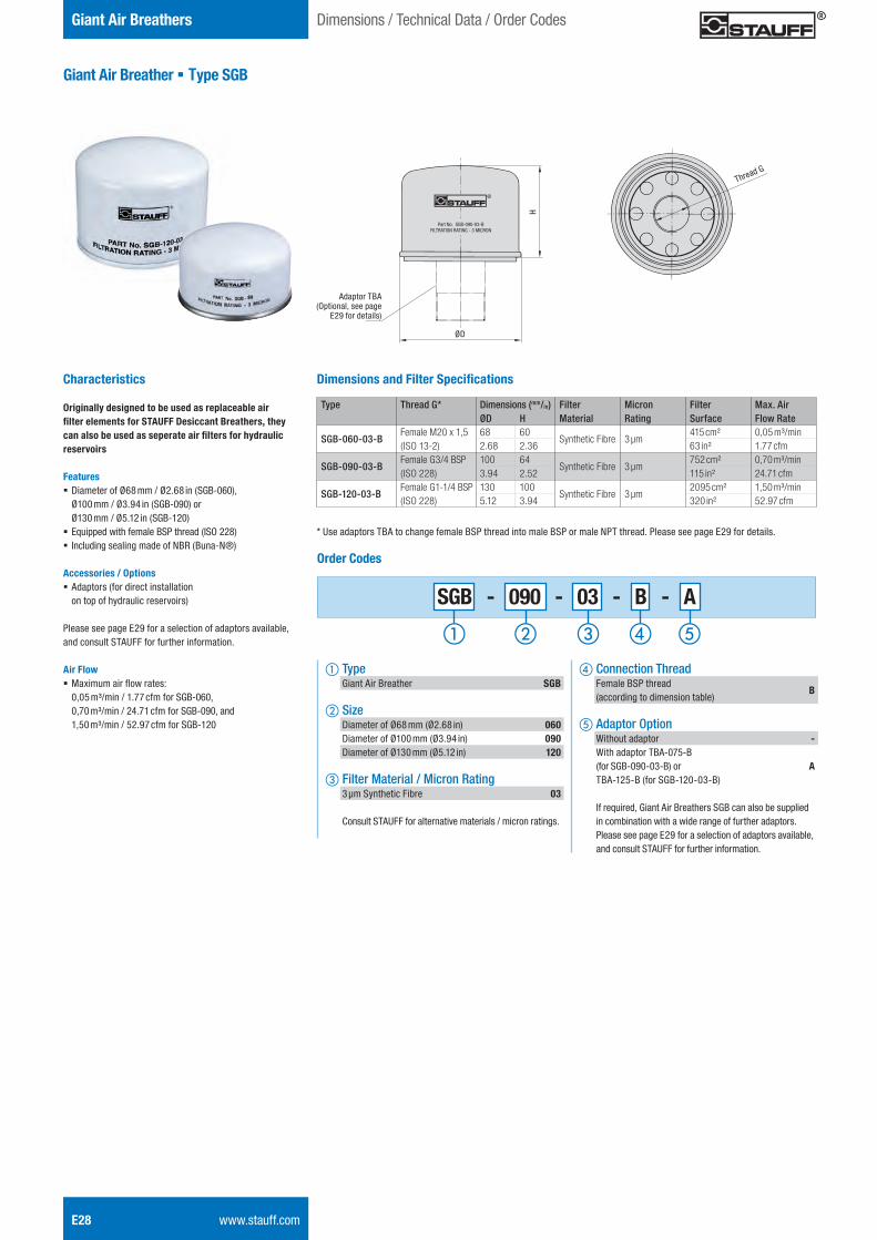
E28 www.stauff.com
Giant Air Breathers
Giant Air Breather § Type SGB
Characteristics
Originally designed to be used as replaceable air filter elements for STAUFF Desiccant Breathers, they can also be used as seperate air filters for hydraulic reservoirs
Features § Diameter of Ø68 mm / Ø2.68 in (SGB-060), Ø100 mm / Ø3.94 in (SGB-090) or Ø130 mm / Ø5.12 in (SGB-120)
§ Equipped with female BSP thread (ISO 228) § Including sealing made of NBR (Buna-N®)
Accessories / Options § Adaptors (for direct installation on top of hydraulic reservoirs)
Please see page E29 for a selection of adaptors available, and consult STAUFF for further information. Air Flow § Maximum air flow rates: 0,05 m³/min / 1.77 cfm for SGB-060, 0,70 m³/min / 24.71 cfm for SGB-090, and 1,50 m³/min / 52.97 cfm for SGB-120
d Connection Thread Female BSP thread (according to dimension table)
B
e Adaptor Option Without adaptor - With adaptor TBA-075-B (for SGB-090-03-B) or A TBA-125-B (for SGB-120-03-B) If required, Giant Air Breathers SGB can also be supplied in combination with a wide range of further adaptors. Please see page E29 for a selection of adaptors available, and consult STAUFF for further information.
Order Codes
a Type Giant Air Breather SGB
b Size Diameter of Ø68 mm (Ø2.68 in) 060 Diameter of Ø100 mm (Ø3.94 in) 090 Diameter of Ø130 mm (Ø5.12 in) 120
c Filter Material / Micron Rating 3 μm Synthetic Fibre 03
Consult STAUFF for alternative materials / micron ratings.
Dimensions / Technical Data / Order Codes
Part No. SGB-090-03-B
FILTRATION RATING - 3 MICRON
Thread G
ØD
H
SGB - 090 - 03 - B - A
Dimensions and Filter Specifications
Type Thread G* Dimensions (mm/in) Filter Micron Filter Max. Air ØD H Material Rating Surface Flow Rate
SGB-060-03-BFemale M20 x 1,5(ISO 13-2)
68 60Synthetic Fibre 3 μm
415 cm² 0,05 m³/min2.68 2.36 63 in² 1.77 cfm
SGB-090-03-BFemale G3/4 BSP(ISO 228)
100 64Synthetic Fibre 3 μm
752 cm² 0,70 m³/min3.94 2.52 115 in² 24.71 cfm
SGB-120-03-BFemale G1-1/4 BSP(ISO 228)
130 100Synthetic Fibre 3 μm
2095 cm² 1,50 m³/min5.12 3.94 320 in² 52.97 cfm
* Use adaptors TBA to change female BSP thread into male BSP or male NPT thread. Please see page E29 for details.
Adaptor TBA (Optional, see page
E29 for details)
STAUFF ONE - Hydraulic Accessories - English.indd 28 23.11.2013 12:33:56
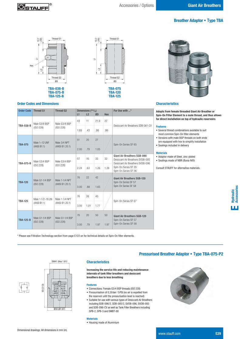
Hydr
aulic
Ac
cess
orie
sE
Giant Air BreathersAccessories / Options
www.stauff.com E29
Breather Adaptor § Type TBA
Dimensional drawings: All dimensions in mm (in).
Characteristics
Adopts from female threaded Giant Air Breather or Spin-On Filter Element to a male thread, and thus allows for direct installation on top of hydraulic reservoirs
Features § Several thread combinations available to suitmost common Spin-On fi lter elements
§ Versions with male BSP threads on both ends are equipped with hex to simplify installation
§ Sealings included in delivery
Materials § Adaptor made of Steel, zinc-plated§ Sealings made of NBR (Buna-N®)
Consult STAUFF for alternative materials.
Order Codes and Dimensions
TBA-038-BTBA-075-BTBA-125-B
TBA-075TBA-120TBA-125
Thread G2
Thread G112
,7
(.50)
12,7
(.5
0) Thread G1
Thread G2
L1 L1
Hex
L2 L2
ØD ØD
Order Code Thread G1 Thread G2 Dimensions (mm/in) For Use with ...*L1 L2 ØD Hex
TBA-038-BMale G3/8 BSP(ISO 228)
Male G3/8 BSP(ISO 228)
43 11 21,9 22
Desiccant Air Breathers SDB-061-CV
1.69 .43 .86 .86
TBA-075Male 1–12 UNF(ANSI B1.1)
Male 3/4 NPT(ANSI B1.20.1)
51 20 27
Spin-On Series SF 65
2.00 .79 1.05
TBA-075-BMale G3/4 BSP(ISO 228)
Male G3/4 BSP(ISO 228)
57 16 32 32Giant Air Breathers SGB-090Desiccant Air Breathers SVDB-093Desiccant Air Breathers SVDB-096 Spin-On Series SF 35Spin-On Series SF 36
2.24 .63 1.26 1.26
TBA-120Male G1-1/4 BSP(ISO 228)
Male 1-1/4 NPT(ANSI B1.20.1)
76 22 42 Giant Air Breathers SGB-120Spin-On Series SF 57Spin-On Series SF 583.00 .88 1.65
TBA-125Male 1-1/2–16 UN(ANSI B1.1)
Male 1-1/4 NPT(ANSI B1.20.1)
76 26 45
Spin-On Series SF 67
3.00 1.01 1.77
TBA-125-BMale G1-1/4 BSP(ISO 228)
Male G1-1/4 BSP(ISO 228)
76 20 50 50 Giant Air Breathers SGB-120Spin-On Series SF 57Spin-On Series SF 583.00 .79 1.97 1.97
* Please see Filtration Technology section from page C122 on for technical details on Spin-On fi lter elements.
Pressurised Breather Adaptor § Type TBA-075-P2
Characteristics
Increasing the service life and reducing maintenance intervals of tank fi ller breathers and desiccant breathers due to less breathing
Features § Connections: Female G3/4 BSP threads (ISO 228) § Pressurisation of 0,35 bar / 5 PSI (no air is expelled from the reservoir until the pressurisation level is reached)
§ Suitable for use with various types of Desiccant Air Breathers including SDB-096/2, SDB-093/2, SVDB-096, SVDB-093 and SDB-096-CV as well as Tank Filler Breathers including SPB-2, SPB-3 and SMBT-80
Materials § Housing made of Aluminium
SW41 (Hex 1.61)
93 (3
.12)
Ø50 (Ø1.97)
STAUFF ONE - Hydraulic Accessories - English.indd 29 23.11.2013 12:33:58
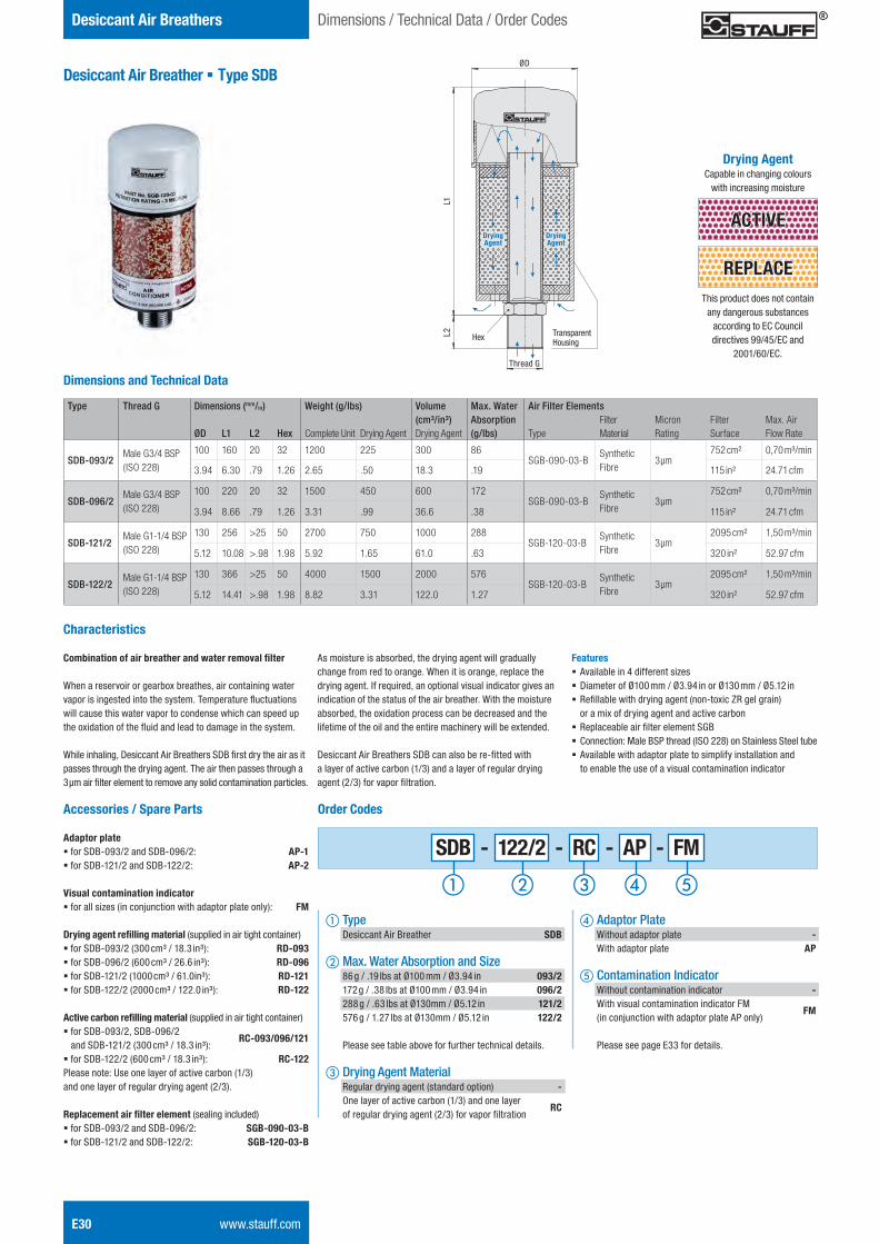
E30 www.stauff.com
Desiccant Air Breathers
Desiccant Air Breather § Type SDB
Dimensions / Technical Data / Order Codes
Dimensions and Technical Data
Type Thread G Dimensions (mm/in) Weight (g/lbs) Volume Max. Water Air Filter Elements(cm³/in³) Absorption Filter Micron Filter Max. Air
ØD L1 L2 Hex Complete Unit Drying Agent Drying Agent (g/lbs) Type Material Rating Surface Flow Rate
SDB-093/2Male G3/4 BSP(ISO 228)
100 160 20 32 1200 225 300 86SGB-090-03-B
Synthetic Fibre
3 μm752 cm² 0,70 m³/min
3.94 6.30 .79 1.26 2.65 .50 18.3 .19 115 in² 24.71 cfm
SDB-096/2Male G3/4 BSP(ISO 228)
100 220 20 32 1500 450 600 172SGB-090-03-B
Synthetic Fibre
3 μm752 cm² 0,70 m³/min
3.94 8.66 .79 1.26 3.31 .99 36.6 .38 115 in² 24.71 cfm
SDB-121/2Male G1-1/4 BSP(ISO 228)
130 256 >25 50 2700 750 1000 288SGB-120-03-B
Synthetic Fibre
3 μm2095 cm² 1,50 m³/min
5.12 10.08 >.98 1.98 5.92 1.65 61.0 .63 320 in² 52.97 cfm
SDB-122/2Male G1-1/4 BSP(ISO 228)
130 366 >25 50 4000 1500 2000 576SGB-120-03-B
Synthetic Fibre
3 μm2095 cm² 1,50 m³/min
5.12 14.41 >.98 1.98 8.82 3.31 122.0 1.27 320 in² 52.97 cfm
Order Codes
SDB - 122/2 - RC - AP - FM
Accessories / Spare Parts Adaptor plate § for SDB-093/2 and SDB-096/2: AP-1 § for SDB-121/2 and SDB-122/2: AP-2 Visual contamination indicator § for all sizes (in conjunction with adaptor plate only): FM Drying agent refilling material (supplied in air tight container) § for SDB-093/2 (300 cm³ / 18.3 in³): RD-093 § for SDB-096/2 (600 cm³ / 26.6 in³): RD-096 § for SDB-121/2 (1000 cm³ / 61.0in³): RD-121 § for SDB-122/2 (2000 cm³ / 122.0 in³): RD-122 Active carbon refilling material (supplied in air tight container) § for SDB-093/2, SDB-096/2 and SDB-121/2 (300 cm³ / 18.3 in³):
RC-093/096/121
§ for SDB-122/2 (600 cm³ / 18.3 in³): RC-122 Please note: Use one layer of active carbon (1/3) and one layer of regular drying agent (2/3). Replacement air filter element (sealing included) § for SDB-093/2 and SDB-096/2: SGB-090-03-B § for SDB-121/2 and SDB-122/2: SGB-120-03-B
a Type Desiccant Air Breather SDB
b Max. Water Absorption and Size 86 g / .19 lbs at Ø100 mm / Ø3.94 in 093/2 172 g / .38 lbs at Ø100 mm / Ø3.94 in 096/2 288 g / .63 lbs at Ø130mm / Ø5.12 in 121/2 576 g / 1.27 lbs at Ø130mm / Ø5.12 in 122/2 Please see table above for further technical details.
c Drying Agent Material Regular drying agent (standard option) - One layer of active carbon (1/3) and one layer of regular drying agent (2/3) for vapor filtration
RC
d Adaptor Plate Without adaptor plate - With adaptor plate AP
e Contamination Indicator Without contamination indicator - With visual contamination indicator FM (in conjunction with adaptor plate AP only)
FM
Please see page E33 for details.
This product does not contain any dangerous substances
according to EC Council directives 99/45/EC and
2001/60/EC.
REPLACE
ACTIVE
Drying Agent Capable in changing colours
with increasing moisture
Drying Agent
Drying Agent
Thread G
TransparentHousing
HexL2L1
ØD
Characteristics
Combination of air breather and water removal filter
When a reservoir or gearbox breathes, air containing water vapor is ingested into the system. Temperature fluctuations will cause this water vapor to condense which can speed up the oxidation of the fluid and lead to damage in the system.
While inhaling, Desiccant Air Breathers SDB first dry the air as it passes through the drying agent. The air then passes through a 3 μm air filter element to remove any solid contamination particles.
As moisture is absorbed, the drying agent will gradually change from red to orange. When it is orange, replace the drying agent. If required, an optional visual indicator gives an indication of the status of the air breather. With the moisture absorbed, the oxidation process can be decreased and the lifetime of the oil and the entire machinery will be extended.
Desiccant Air Breathers SDB can also be re-fitted with a layer of active carbon (1/3) and a layer of regular drying agent (2/3) for vapor filtration.
Features § Available in 4 different sizes § Diameter of Ø100 mm / Ø3.94 in or Ø130 mm / Ø5.12 in § Refillable with drying agent (non-toxic ZR gel grain) or a mix of drying agent and active carbon
§ Replaceable air filter element SGB § Connection: Male BSP thread (ISO 228) on Stainless Steel tube § Available with adaptor plate to simplify installation and to enable the use of a visual contamination indicator
STAUFF ONE - Hydraulic Accessories - English.indd 30 23.11.2013 12:33:59
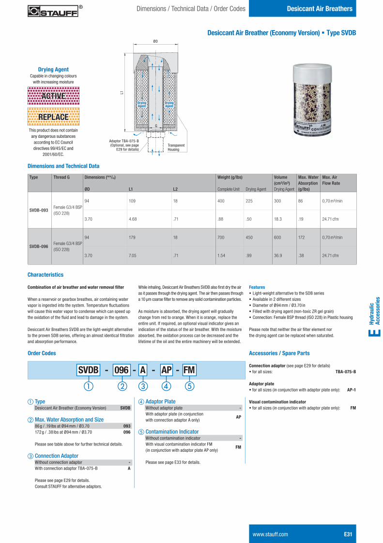
Hydr
aulic
Ac
cess
orie
sE
Desiccant Air BreathersDimensions / Technical Data / Order Codes
www.stauff.com E31
Desiccant Air Breather (Economy Version) § Type SVDB
Dimensions and Technical Data
Type Thread G Dimensions (mm/in) Weight (g/lbs) Volume Max. Water Max. Air(cm³/in³) Absorption Flow Rate
ØD L1 L2 Complete Unit Drying Agent Drying Agent (g/lbs)
SVDB-093Female G3/4 BSP(ISO 228)
94 109 18 400 225 300 86 0,70 m³/min
3.70 4.68 .71 .88 .50 18.3 .19 24.71 cfm
SVDB-096Female G3/4 BSP(ISO 228)
94 179 18 700 450 600 172 0,70 m³/min
3.70 7.05 .71 1.54 .99 36.9 .38 24.71 cfm
Order Codes
SVDB - 096 - A - AP - FM
a Type Desiccant Air Breather (Economy Version) SVDB
b Max. Water Absorption and Size 86 g / .19 lbs at Ø94 mm / Ø3.70 093 172 g / .38 lbs at Ø94 mm / Ø3.70 096 Please see table above for further technical details.
c Connection Adaptor Without connection adaptor - With connection adaptor TBA-075-B A
Please see page E29 for details. Consult STAUFF for alternative adaptors.
d Adaptor Plate Without adaptor plate - With adaptor plate (in conjunction with connection adaptor A only)
AP
e Contamination Indicator Without contamination indicator - With visual contamination indicator FM (in conjunction with adaptor plate AP only)
FM
Please see page E33 for details.
This product does not contain any dangerous substances
according to EC Council directives 99/45/EC and
2001/60/EC.
REPLACE
ACTIVE
Drying Agent Capable in changing colours
with increasing moisture
Drying Agent
Drying Agent
TransparentHousing
L1
ØD
Combination of air breather and water removal filter
When a reservoir or gearbox breathes, air containing water vapor is ingested into the system. Temperature fluctuations will cause this water vapor to condense which can speed up the oxidation of the fluid and lead to damage in the system.
Desiccant Air Breathers SVDB are the light-weight alternative to the proven SDB series, offering an almost identical filtration and absorption performance.
While inhaling, Desiccant Air Breathers SVDB also first dry the air as it passes through the drying agent. The air then passes through a 10 μm coarse filter to remove any solid contamination particles. As moisture is absorbed, the drying agent will gradually change from red to orange. When it is orange, replace the entire unit. If required, an optional visual indicator gives an indication of the status of the air breather. With the moisture absorbed, the oxidation process can be decreased and the lifetime of the oil and the entire machinery will be extended.
Features § Light-weight alternative to the SDB series § Available in 2 different sizes § Diameter of Ø94 mm / Ø3.70 in § Filled with drying agent (non-toxic ZR gel grain) § Connection: Female BSP thread (ISO 228) in Plastic housing
Please note that neither the air filter element nor the drying agent can be replaced when saturated.
Characteristics
Accessories / Spare Parts Connection adaptor (see page E29 for details) § for all sizes: TBA-075-B Adaptor plate § for all sizes (in conjunction with adaptor plate only): AP-1 Visual contamination indicator § for all sizes (in conjunction with adaptor plate only): FM
Adaptor TBA-075-B (Optional, see page
E29 for details)
G
STAUFF ONE - Hydraulic Accessories - English.indd 31 23.11.2013 12:34:01
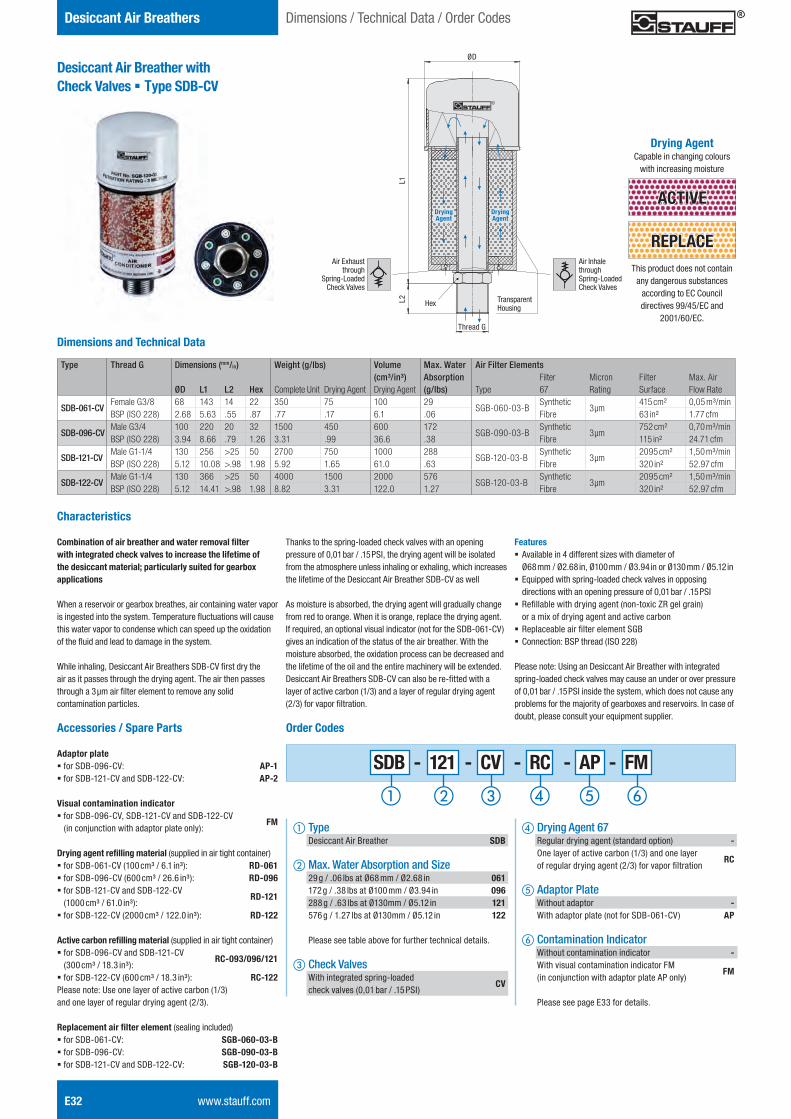
E32 www.stauff.com
Desiccant Air Breathers
Desiccant Air Breather with Check Valves § Type SDB-CV
Dimensions / Technical Data / Order Codes
Dimensions and Technical Data
Type Thread G Dimensions (mm/in) Weight (g/lbs) Volume Max. Water Air Filter Elements(cm³/in³) Absorption Filter Micron Filter Max. Air
ØD L1 L2 Hex Complete Unit Drying Agent Drying Agent (g/lbs) Type 67 Rating Surface Flow Rate
SDB-061-CVFemale G3/8 BSP (ISO 228)
68 143 14 22 350 75 100 29SGB-060-03-B
SyntheticFibre
3 μm415 cm² 0,05 m³/min
2.68 5.63 .55 .87 .77 .17 6.1 .06 63 in² 1.77 cfm
SDB-096-CVMale G3/4 BSP (ISO 228)
100 220 20 32 1500 450 600 172SGB-090-03-B
SyntheticFibre
3 μm752 cm² 0,70 m³/min
3.94 8.66 .79 1.26 3.31 .99 36.6 .38 115 in² 24.71 cfm
SDB-121-CVMale G1-1/4 BSP (ISO 228)
130 256 >25 50 2700 750 1000 288SGB-120-03-B
SyntheticFibre
3 μm2095 cm² 1,50 m³/min
5.12 10.08 >.98 1.98 5.92 1.65 61.0 .63 320 in² 52.97 cfm
SDB-122-CVMale G1-1/4 BSP (ISO 228)
130 366 >25 50 4000 1500 2000 576SGB-120-03-B
SyntheticFibre
3 μm2095 cm² 1,50 m³/min
5.12 14.41 >.98 1.98 8.82 3.31 122.0 1.27 320 in² 52.97 cfm
Order CodesAccessories / Spare Parts
Adaptor plate § for SDB-096-CV: AP-1§ for SDB-121-CV and SDB-122-CV: AP-2
Visual contamination indicator § for SDB-096-CV, SDB-121-CV and SDB-122-CV (in conjunction with adaptor plate only):
FM
Drying agent refi lling material (supplied in air tight container)§ for SDB-061-CV (100 cm³ / 6.1 in³): RD-061§ for SDB-096-CV (600 cm³ / 26.6 in³): RD-096§ for SDB-121-CV and SDB-122-CV (1000 cm³ / 61.0 in³):
RD-121
§ for SDB-122-CV (2000 cm³ / 122.0 in³): RD-122
Active carbon refi lling material (supplied in air tight container)§ for SDB-096-CV and SDB-121-CV (300 cm³ / 18.3 in³):
RC-093/096/121
§ for SDB-122-CV (600 cm³ / 18.3 in³): RC-122Please note: Use one layer of active carbon (1/3) and one layer of regular drying agent (2/3).
Replacement air fi lter element (sealing included)§ for SDB-061-CV: SGB-060-03-B§ for SDB-096-CV: SGB-090-03-B§ for SDB-121-CV and SDB-122-CV: SGB-120-03-B
a Type Desiccant Air Breather SDB
b Max. Water Absorption and Size 29 g / .06 lbs at Ø68 mm / Ø2.68 in 061 172 g / .38 lbs at Ø100 mm / Ø3.94 in 096 288 g / .63 lbs at Ø130mm / Ø5.12 in 121 576 g / 1.27 lbs at Ø130mm / Ø5.12 in 122
Please see table above for further technical details.
c Check Valves With integrated spring-loaded check valves (0,01 bar / .15 PSI)
CV
d Drying Agent 67 Regular drying agent (standard option) - One layer of active carbon (1/3) and one layer of regular drying agent (2/3) for vapor fi ltration
RC
e Adaptor Plate Without adaptor - With adaptor plate (not for SDB-061-CV) AP
f Contamination Indicator Without contamination indicator - With visual contamination indicator FM (in conjunction with adaptor plate AP only)
FM
Please see page E33 for details.
SDB - 121 - CV - RC - AP - FM
This product does not contain any dangerous substances
according to EC Council directives 99/45/EC and
2001/60/EC.
REPLACE
ACTIVE
Drying Agent Capable in changing colours
with increasing moisture
Drying Agent
Drying Agent
Thread G
TransparentHousing
HexL2L1
ØD
Characteristics
Combination of air breather and water removal fi lter with integrated check valves to increase the lifetime of the desiccant material; particularly suited for gearbox applications
When a reservoir or gearbox breathes, air containing water vapor is ingested into the system. Temperature fl uctuations will cause this water vapor to condense which can speed up the oxidation of the fl uid and lead to damage in the system.
While inhaling, Desiccant Air Breathers SDB-CV fi rst dry the air as it passes through the drying agent. The air then passes through a 3 μm air fi lter element to remove any solid contamination particles.
Thanks to the spring-loaded check valves with an opening pressure of 0,01 bar / .15 PSI, the drying agent will be isolated from the atmosphere unless inhaling or exhaling, which increases the lifetime of the Desiccant Air Breather SDB-CV as well
As moisture is absorbed, the drying agent will gradually change from red to orange. When it is orange, replace the drying agent. If required, an optional visual indicator (not for the SDB-061-CV) gives an indication of the status of the air breather. With the moisture absorbed, the oxidation process can be decreased and the lifetime of the oil and the entire machinery will be extended.Desiccant Air Breathers SDB-CV can also be re-fi tted with a layer of active carbon (1/3) and a layer of regular drying agent (2/3) for vapor fi ltration.
Features § Available in 4 different sizes with diameter of Ø68 mm / Ø2.68 in, Ø100 mm / Ø3.94 in or Ø130 mm / Ø5.12 in
§ Equipped with spring-loaded check valves in opposing directions with an opening pressure of 0,01 bar / .15 PSI
§ Refi llable with drying agent (non-toxic ZR gel grain) or a mix of drying agent and active carbon
§ Replaceable air fi lter element SGB § Connection: BSP thread (ISO 228)
Please note: Using an Desiccant Air Breather with integratedspring-loaded check valves may cause an under or over pressure of 0,01 bar / .15 PSI inside the system, which does not cause any problems for the majority of gearboxes and reservoirs. In case of doubt, please consult your equipment supplier.
Air Exhaust through
Spring-Loaded Check Valves
Air Inhalethrough Spring-Loaded Check Valves
STAUFF ONE - Hydraulic Accessories - English.indd 32 23.11.2013 12:34:04
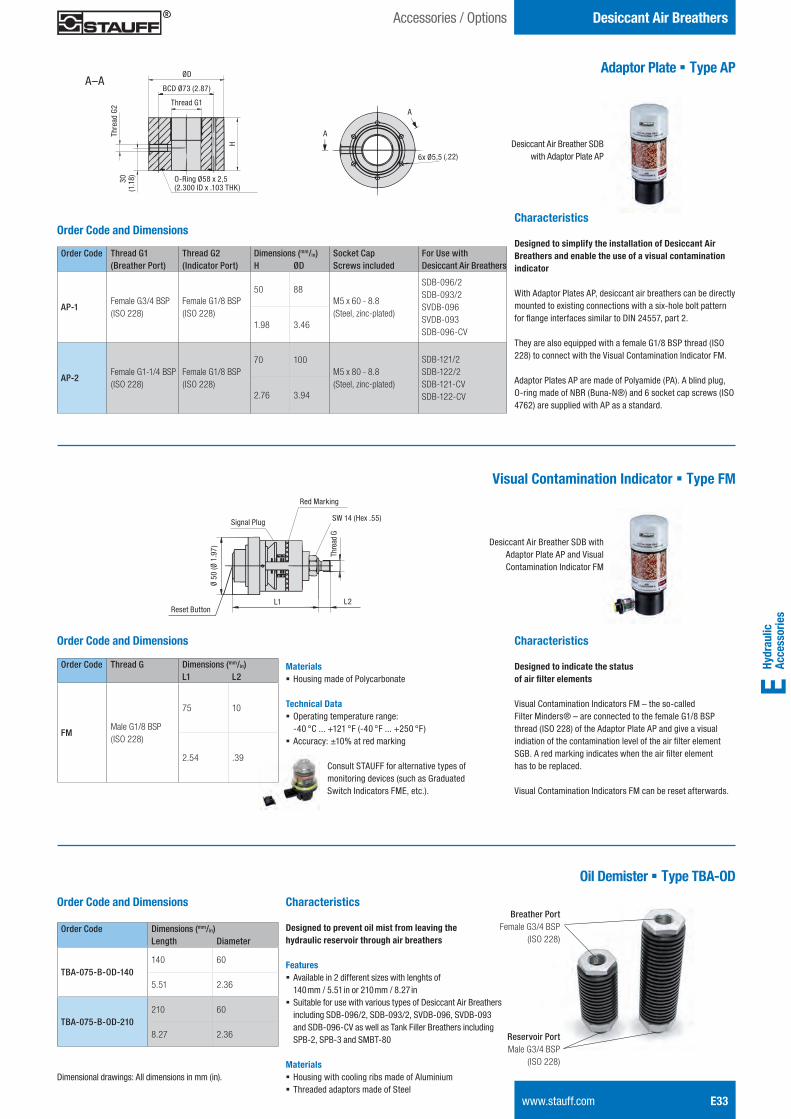
Hydr
aulic
Ac
cess
orie
sE
Desiccant Air BreathersAccessories / Options
www.stauff.com E33
Dimensional drawings: All dimensions in mm (in).
Adaptor Plate § Type AP
Characteristics
Designed to simplify the installation of Desiccant Air Breathers and enable the use of a visual contamination indicator
With Adaptor Plates AP, desiccant air breathers can be directly mounted to existing connections with a six-hole bolt pattern for flange interfaces similar to DIN 24557, part 2.
They are also equipped with a female G1/8 BSP thread (ISO 228) to connect with the Visual Contamination Indicator FM.
Adaptor Plates AP are made of Polyamide (PA). A blind plug, O-ring made of NBR (Buna-N®) and 6 socket cap screws (ISO 4762) are supplied with AP as a standard.
Visual Contamination Indicator § Type FM
Characteristics
Designed to indicate the status of air filter elements
Visual Contamination Indicators FM – the so-called Filter Minders® – are connected to the female G1/8 BSP thread (ISO 228) of the Adaptor Plate AP and give a visual indiation of the contamination level of the air filter element SGB. A red marking indicates when the air filter element has to be replaced.
Visual Contamination Indicators FM can be reset afterwards.
Order Code Thread G1 Thread G2 Dimensions (mm/in) Socket Cap For Use with (Breather Port) (Indicator Port) H ØD Screws included Desiccant Air Breathers
AP-1Female G3/4 BSP(ISO 228)
Female G1/8 BSP(ISO 228)
50 88M5 x 60 - 8.8 (Steel, zinc-plated)
SDB-096/2 SDB-093/2 SVDB-096 SVDB-093 SDB-096-CV
1.98 3.46
AP-2Female G1-1/4 BSP(ISO 228)
Female G1/8 BSP(ISO 228)
70 100M5 x 80 - 8.8 (Steel, zinc-plated)
SDB-121/2 SDB-122/2 SDB-121-CV SDB-122-CV2.76 3.94
Order Code and Dimensions
6x Ø5,5 (.22)
A
ADesiccant Air Breather SDB
with Adaptor Plate AP
Desiccant Air Breather SDB with Adaptor Plate AP and Visual Contamination Indicator FM
Order Code Thread G Dimensions (mm/in)L1 L2
FMMale G1/8 BSP(ISO 228)
75 10
2.54 .39
Order Code and Dimensions
Materials § Housing made of Polycarbonate
Technical Data § Operating temperature range: -40 °C ... +121 °F (-40 °F ... +250 °F)
§ Accuracy: ±10% at red marking
Oil Demister § Type TBA-OD
Characteristics
Designed to prevent oil mist from leaving the hydraulic reservoir through air breathers Features § Available in 2 different sizes with lenghts of 140 mm / 5.51 in or 210 mm / 8.27 in
§ Suitable for use with various types of Desiccant Air Breathers including SDB-096/2, SDB-093/2, SVDB-096, SVDB-093 and SDB-096-CV as well as Tank Filler Breathers including SPB-2, SPB-3 and SMBT-80
Materials § Housing with cooling ribs made of Aluminium § Threaded adaptors made of Steel
Thread G1
ØD
Thre
ad G
230
(1
.18)
H
O-Ring Ø58 x 2,5(2.300 ID x .103 THK)
BCD Ø73 (2.87)A–A
Red Marking
Signal Plug
Reset ButtonL1 L2
Thre
ad G
SW 14 (Hex .55)
Order Code Dimensions (mm/in)Length Diameter
TBA-075-B-OD-140140 60
5.51 2.36
TBA-075-B-OD-210210 60
8.27 2.36
Order Code and DimensionsBreather Port
Female G3/4 BSP(ISO 228)
Reservoir Port Male G3/4 BSP
(ISO 228)
Ø 50
(Ø 1
.97)
Consult STAUFF for alternative types of monitoring devices (such as Graduated Switch Indicators FME, etc.).
STAUFF ONE - Hydraulic Accessories - English.indd 33 23.11.2013 12:34:06
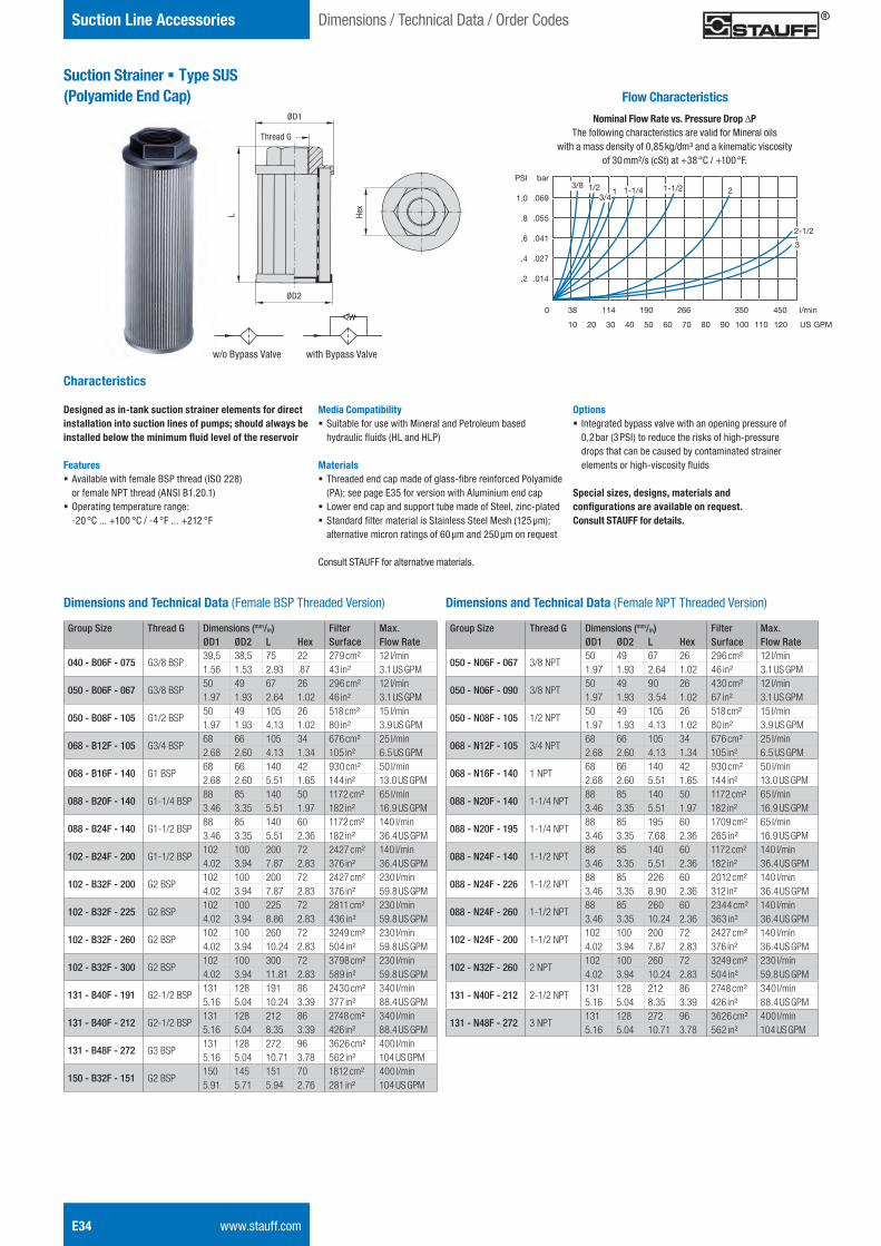
E34 www.stauff.com
Suction Line Accessories
Suction Strainer § Type SUS (Polyamide End Cap)
Characteristics
Designed as in-tank suction strainer elements for direct installation into suction lines of pumps; should always be installed below the minimum fluid level of the reservoir
Features § Available with female BSP thread (ISO 228) or female NPT thread (ANSI B1.20.1)
§ Operating temperature range: -20 °C ... +100 °C / -4 °F ... +212 °F
Dimensions / Technical Data / Order Codes
Group Size Thread G Dimensions (mm/in) Filter Max.ØD1 ØD2 L Hex Surface Flow Rate
040 - B06F - 075 G3/8 BSP39,5 38,5 75 22 279 cm² 12 l/min1.56 1.53 2.93 .87 43 in² 3.1 US GPM
050 - B06F - 067 G3/8 BSP50 49 67 26 296 cm² 12 l/min1.97 1.93 2.64 1.02 46 in² 3.1 US GPM
050 - B08F - 105 G1/2 BSP50 49 105 26 518 cm² 15 l/min1.97 1.93 4.13 1.02 80 in² 3.9 US GPM
068 - B12F - 105 G3/4 BSP68 66 105 34 676 cm² 25 l/min2.68 2.60 4.13 1.34 105 in² 6.5 US GPM
068 - B16F - 140 G1 BSP68 66 140 42 930 cm² 50 l/min2.68 2.60 5.51 1.65 144 in² 13.0 US GPM
088 - B20F - 140 G1-1/4 BSP88 85 140 50 1172 cm² 65 l/min3.46 3.35 5.51 1.97 182 in² 16.9 US GPM
088 - B24F - 140 G1-1/2 BSP88 85 140 60 1172 cm² 140 l/min3.46 3.35 5.51 2.36 182 in² 36.4 US GPM
102 - B24F - 200 G1-1/2 BSP102 100 200 72 2427 cm² 140 l/min4.02 3.94 7.87 2.83 376 in² 36.4 US GPM
102 - B32F - 200 G2 BSP102 100 200 72 2427 cm² 230 l/min4.02 3.94 7.87 2.83 376 in² 59.8 US GPM
102 - B32F - 225 G2 BSP102 100 225 72 2811 cm² 230 l/min4.02 3.94 8.86 2.83 436 in² 59.8 US GPM
102 - B32F - 260 G2 BSP102 100 260 72 3249 cm² 230 l/min4.02 3.94 10.24 2.83 504 in² 59.8 US GPM
102 - B32F - 300 G2 BSP102 100 300 72 3798 cm² 230 l/min4.02 3.94 11.81 2.83 589 in² 59.8 US GPM
131 - B40F - 191 G2-1/2 BSP131 128 191 86 2430 cm² 340 l/min5.16 5.04 10.24 3.39 377 in² 88.4 US GPM
131 - B40F - 212 G2-1/2 BSP131 128 212 86 2748 cm² 340 l/min5.16 5.04 8.35 3.39 426 in² 88.4 US GPM
131 - B48F - 272 G3 BSP131 128 272 96 3626 cm² 400 l/min5.16 5.04 10.71 3.78 562 in² 104 US GPM
150 - B32F - 151 G2 BSP150 145 151 70 1812 cm² 400 l/min5.91 5.71 5.94 2.76 281 in² 104 US GPM
Group Size Thread G Dimensions (mm/in) Filter Max.ØD1 ØD2 L Hex Surface Flow Rate
050 - N06F - 067 3/8 NPT50 49 67 26 296 cm² 12 l/min1.97 1.93 2.64 1.02 46 in² 3.1 US GPM
050 - N06F - 090 3/8 NPT50 49 90 26 430 cm² 12 l/min1.97 1.93 3.54 1.02 67 in² 3.1 US GPM
050 - N08F - 105 1/2 NPT50 49 105 26 518 cm² 15 l/min1.97 1.93 4.13 1.02 80 in² 3.9 US GPM
068 - N12F - 105 3/4 NPT68 66 105 34 676 cm² 25 l/min2.68 2.60 4.13 1.34 105 in² 6.5 US GPM
068 - N16F - 140 1 NPT68 66 140 42 930 cm² 50 l/min2.68 2.60 5.51 1.65 144 in² 13.0 US GPM
088 - N20F - 140 1-1/4 NPT88 85 140 50 1172 cm² 65 l/min3.46 3.35 5.51 1.97 182 in² 16.9 US GPM
088 - N20F - 195 1-1/4 NPT88 85 195 60 1709 cm² 65 l/min3.46 3.35 7.68 2.36 265 in² 16.9 US GPM
088 - N24F - 140 1-1/2 NPT88 85 140 60 1172 cm² 140 l/min3.46 3.35 5.51 2.36 182 in² 36.4 US GPM
088 - N24F - 226 1-1/2 NPT88 85 226 60 2012 cm² 140 l/min3.46 3.35 8.90 2.36 312 in² 36.4 US GPM
088 - N24F - 260 1-1/2 NPT88 85 260 60 2344 cm² 140 l/min3.46 3.35 10.24 2.36 363 in² 36.4 US GPM
102 - N24F - 200 1-1/2 NPT102 100 200 72 2427 cm² 140 l/min4.02 3.94 7.87 2.83 376 in² 36.4 US GPM
102 - N32F - 260 2 NPT102 100 260 72 3249 cm² 230 l/min4.02 3.94 10.24 2.83 504 in² 59.8 US GPM
131 - N40F - 212 2-1/2 NPT131 128 212 86 2748 cm² 340 l/min5.16 5.04 8.35 3.39 426 in² 88.4 US GPM
131 - N48F - 272 3 NPT131 128 272 96 3626 cm² 400 l/min5.16 5.04 10.71 3.78 562 in² 104 US GPM
Dimensions and Technical Data (Female BSP Threaded Version) Dimensions and Technical Data (Female NPT Threaded Version)
Media Compatibility § Suitable for use with Mineral and Petroleum based hydraulic fluids (HL and HLP)
Materials § Threaded end cap made of glass-fibre reinforced Polyamide (PA); see page E35 for version with Aluminium end cap
§ Lower end cap and support tube made of Steel, zinc-plated § Standard filter material is Stainless Steel Mesh (125 μm); alternative micron ratings of 60 μm and 250 μm on request
Consult STAUFF for alternative materials.
Options § Integrated bypass valve with an opening pressure of 0,2 bar (3 PSI) to reduce the risks of high-pressure drops that can be caused by contaminated strainer elements or high-viscosity fluids
Special sizes, designs, materials and configurations are available on request. Consult STAUFF for details.
Hex
ØD1
ØD2
L
Thread G
w/o Bypass Valve with Bypass Valve
Flow Characteristics
Nominal Flow Rate vs. Pressure Drop DPThe following characteristics are valid for Mineral oils
with a mass density of 0,85 kg/dm³ and a kinematic viscosity of 30 mm²/s (cSt) at +38 °C / +100 °F.
bar
.069
.055
.041
.027
.014
0 38 114 190 266 350 450 l/min
10 20 30 40 50 60 70 80 90 100 110 120 US GPM
PSI
1.0
.8
.6
.4
.2
3/8 1/23/4
1 1-1/4 1-1/2 2
2-1/2
3
STAUFF ONE - Hydraulic Accessories - English.indd 34 23.11.2013 12:34:08
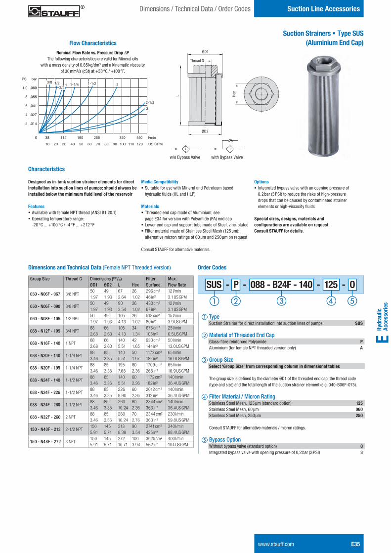
Hydr
aulic
Ac
cess
orie
sE
Suction Line AccessoriesDimensions / Technical Data / Order Codes
Suction Strainers § Type SUS(Aluminium End Cap)
Characteristics
Designed as in-tank suction strainer elements for direct installation into suction lines of pumps; should always be installed below the minimum fluid level of the reservoir
Features § Available with female NPT thread (ANSI B1.20.1) § Operating temperature range: -20 °C ... +100 °C / -4 °F ... +212 °F
Media Compatibility § Suitable for use with Mineral and Petroleum based hydraulic fluids (HL and HLP)
Materials § Threaded end cap made of Aluminium; see page E34 for version with Polyamide (PA) end cap
§ Lower end cap and support tube made of Steel, zinc-plated § Filter material made of Stainless Steel Mesh (125 μm); alternative micron ratings of 60 μm and 250 μm on request
Consult STAUFF for alternative materials.
Options § Integrated bypass valve with an opening pressure of 0,2 bar (3 PSI) to reduce the risks of high-pressure drops that can be caused by contaminated strainer elements or high-viscosity fluids
Special sizes, designs, materials and configurations are available on request. Consult STAUFF for details.
Group Size Thread G Dimensions (mm/in) Filter Max.ØD1 ØD2 L Hex Surface Flow Rate
050 - N06F - 067 3/8 NPT50 49 67 26 296 cm² 12 l/min1.97 1.93 2.64 1.02 46 in² 3.1 US GPM
050 - N06F - 090 3/8 NPT50 49 90 26 430 cm² 12 l/min1.97 1.93 3.54 1.02 67 in² 3.1 US GPM
050 - N08F - 105 1/2 NPT50 49 105 26 518 cm² 15 l/min1.97 1.93 4.13 1.02 80 in² 3.9 US GPM
068 - N12F - 105 3/4 NPT68 66 105 34 676 cm² 25 l/min2.68 2.60 4.13 1.34 105 in² 6.5 US GPM
068 - N16F - 140 1 NPT68 66 140 42 930 cm² 50 l/min2.68 2.60 5.51 1.65 144 in² 13.0 US GPM
088 - N20F - 140 1-1/4 NPT88 85 140 50 1172 cm² 65 l/min3.46 3.35 5.51 1.97 182 in² 16.9 US GPM
088 - N20F - 195 1-1/4 NPT88 85 195 60 1709 cm² 65 l/min3.46 3.35 7.68 2.36 265 in² 16.9 US GPM
088 - N24F - 140 1-1/2 NPT88 85 140 60 1172 cm² 140 l/min3.46 3.35 5.51 2.36 182 in² 36.4 US GPM
088 - N24F - 226 1-1/2 NPT88 85 226 60 2012 cm² 140 l/min3.46 3.35 8.90 2.36 312 in² 36.4 US GPM
088 - N24F - 260 1-1/2 NPT88 85 260 60 2344 cm² 140 l/min3.46 3.35 10.24 2.36 363 in² 36.4 US GPM
088 - N32F - 260 2 NPT88 85 260 70 2344 cm² 230 l/min3.46 3.35 10.24 2.76 363 in² 59.8 US GPM
150 - N40F - 213 2-1/2 NPT150 145 213 90 2741 cm² 340 l/min5.91 5.71 8.39 3.54 425 in² 88.4 US GPM
150 - N48F - 272 3 NPT150 145 272 100 3625 cm² 400 l/min5.91 5.71 10.71 3.94 562 in² 104 US GPM
Dimensions and Technical Data (Female NPT Threaded Version)
Hex
ØD1
ØD2
L
Thread G
w/o Bypass Valve with Bypass Valve
Order Codes
a Type Suction Strainer for direct installation into suction lines of pumps SUS
b Material of Threaded End Cap Glass-fibre reinforced Polyamide P Aluminium (for female NPT threaded version only) A c Group Size Select ‘Group Size’ from corresponding column in dimensional tables
The group size is defined by the diameter ØD1 of the threaded end cap, the thread code (type and size) and the total length of the suction strainer element (e.g. 040-B06F-075).
d Filter Material / Micron Rating Stainless Steel Mesh, 125 μm (standard option) 125 Stainless Steel Mesh, 60 μm 060 Stainless Steel Mesh, 250 μm 250
Consult STAUFF for alternative materials / micron ratings.
e Bypass Option Without bypass valve (standard option) 0 Integrated bypass valve with opening pressure of 0,2 bar (3 PSI) 3
Flow Characteristics
Nominal Flow Rate vs. Pressure Drop DPThe following characteristics are valid for Mineral oils
with a mass density of 0,85 kg/dm³ and a kinematic viscosity of 30 mm²/s (cSt) at +38 °C / +100 °F.
bar
.069
.055
.041
.027
.014
0 38 114 190 266 350 450 l/min
10 20 30 40 50 60 70 80 90 100 110 120 US GPM
PSI
1.0
.8
.6
.4
.2
3/8 1/23/4
1 1-1/4 1-1/2 2
2-1/2
3
www.stauff.com E35
SUS - P - 088 - B24F - 140 - 125 - O
STAUFF ONE - Hydraulic Accessories - English.indd 35 23.11.2013 12:34:09
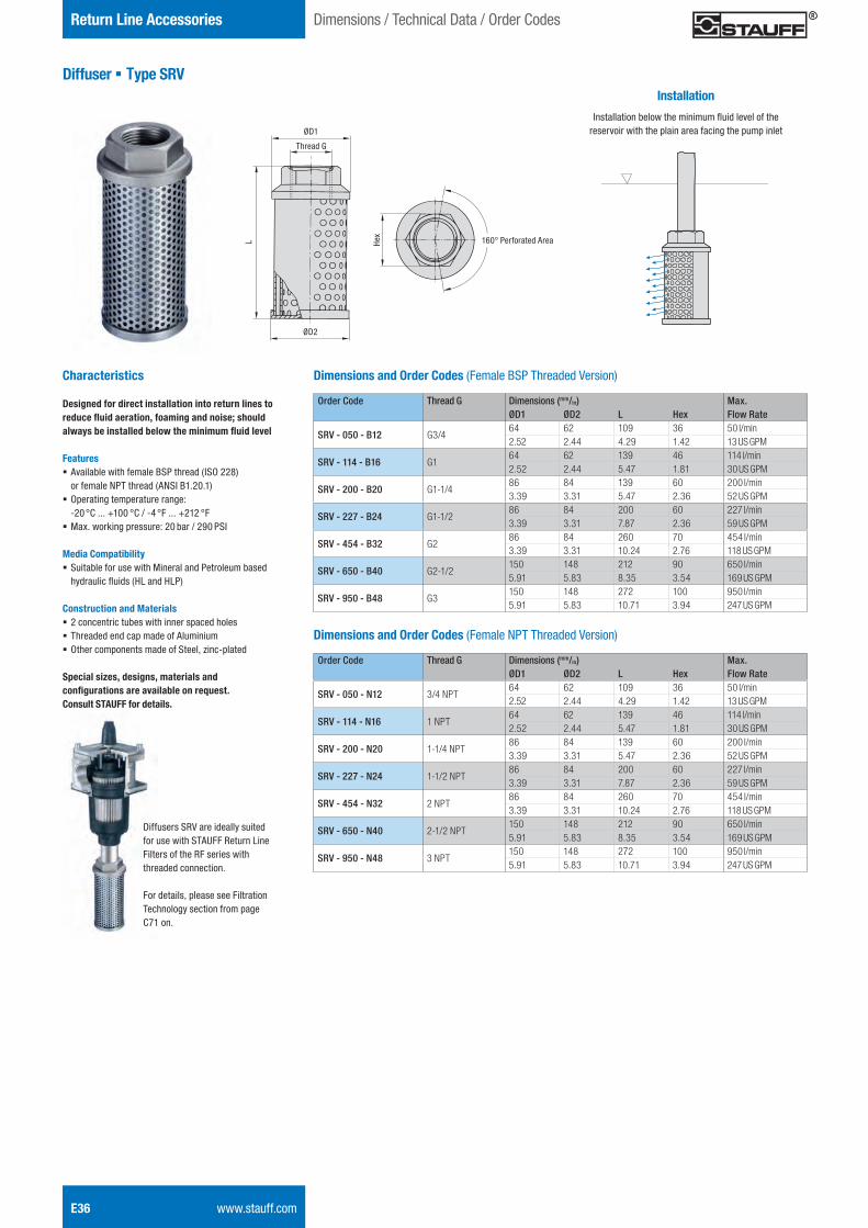
E36 www.stauff.com
Return Line Accessories
Diffuser § Type SRV
Characteristics
Designed for direct installation into return lines to reduce fluid aeration, foaming and noise; should always be installed below the minimum fluid level
Features § Available with female BSP thread (ISO 228) or female NPT thread (ANSI B1.20.1)
§ Operating temperature range: -20 °C ... +100 °C / -4 °F ... +212 °F
§ Max. working pressure: 20 bar / 290 PSI
Media Compatibility § Suitable for use with Mineral and Petroleum based hydraulic fluids (HL and HLP)
Construction and Materials § 2 concentric tubes with inner spaced holes § Threaded end cap made of Aluminium § Other components made of Steel, zinc-plated
Special sizes, designs, materials and configurations are available on request. Consult STAUFF for details.
Dimensions / Technical Data / Order Codes
Order Code Thread G Dimensions (mm/in) Max.ØD1 ØD2 L Hex Flow Rate
SRV - 050 - B12 G3/464 62 109 36 50 l/min2.52 2.44 4.29 1.42 13 US GPM
SRV - 114 - B16 G164 62 139 46 114 l/min2.52 2.44 5.47 1.81 30 US GPM
SRV - 200 - B20 G1-1/486 84 139 60 200 l/min3.39 3.31 5.47 2.36 52 US GPM
SRV - 227 - B24 G1-1/286 84 200 60 227 l/min3.39 3.31 7.87 2.36 59 US GPM
SRV - 454 - B32 G286 84 260 70 454 l/min3.39 3.31 10.24 2.76 118 US GPM
SRV - 650 - B40 G2-1/2150 148 212 90 650 l/min5.91 5.83 8.35 3.54 169 US GPM
SRV - 950 - B48 G3150 148 272 100 950 l/min5.91 5.83 10.71 3.94 247 US GPM
Dimensions and Order Codes (Female BSP Threaded Version)He
x
ØD1
ØD2
L
Thread G
160° Perforated Area
Installation
Installation below the minimum fluid level of the reservoir with the plain area facing the pump inlet
Dimensions and Order Codes (Female NPT Threaded Version)
Order Code Thread G Dimensions (mm/in) Max.ØD1 ØD2 L Hex Flow Rate
SRV - 050 - N12 3/4 NPT64 62 109 36 50 l/min2.52 2.44 4.29 1.42 13 US GPM
SRV - 114 - N16 1 NPT64 62 139 46 114 l/min2.52 2.44 5.47 1.81 30 US GPM
SRV - 200 - N20 1-1/4 NPT86 84 139 60 200 l/min3.39 3.31 5.47 2.36 52 US GPM
SRV - 227 - N24 1-1/2 NPT86 84 200 60 227 l/min3.39 3.31 7.87 2.36 59 US GPM
SRV - 454 - N32 2 NPT86 84 260 70 454 l/min3.39 3.31 10.24 2.76 118 US GPM
SRV - 650 - N40 2-1/2 NPT150 148 212 90 650 l/min5.91 5.83 8.35 3.54 169 US GPM
SRV - 950 - N48 3 NPT150 148 272 100 950 l/min5.91 5.83 10.71 3.94 247 US GPM
Diffusers SRV are ideally suited for use with STAUFF Return Line Filters of the RF series with threaded connection.
For details, please see Filtration Technology section from page C71 on.
STAUFF ONE - Hydraulic Accessories - English.indd 36 23.11.2013 12:34:11
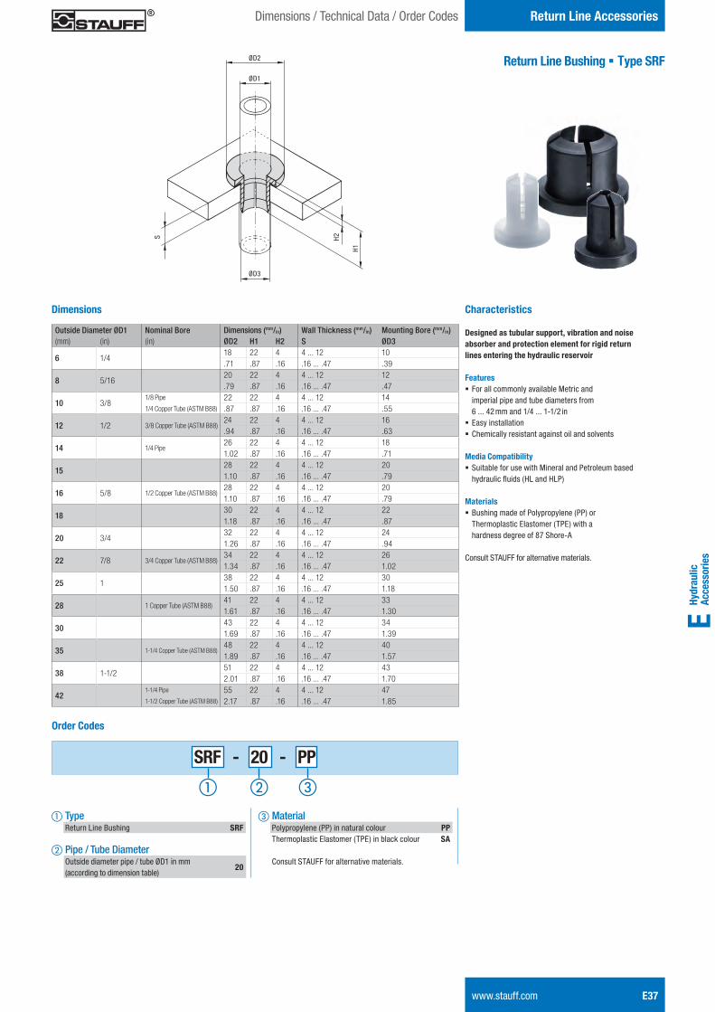
Hydr
aulic
Ac
cess
orie
sE
Return Line Accessories
www.stauff.com E37
Dimensions / Technical Data / Order Codes
Return Line Bushing § Type SRF
Characteristics
Designed as tubular support, vibration and noise absorber and protection element for rigid return lines entering the hydraulic reservoir
Features § For all commonly available Metric and imperial pipe and tube diameters from 6 ... 42 mm and 1/4 ... 1-1/2 in
§ Easy installation § Chemically resistant against oil and solvents
Media Compatibility § Suitable for use with Mineral and Petroleum based hydraulic fluids (HL and HLP)
Materials § Bushing made of Polypropylene (PP) or Thermoplastic Elastomer (TPE) with a hardness degree of 87 Shore-A
Consult STAUFF for alternative materials.
ØD2
ØD1
ØD3
H1
S H2Outside Diameter ØD1 Nominal Bore Dimensions (mm/in) Wall Thickness (mm/in) Mounting Bore (mm/in)(mm) (in) (in) ØD2 H1 H2 S ØD3
6 1/418 22 4 4 ... 12 10.71 .87 .16 .16 ... .47 .39
8 5/1620 22 4 4 ... 12 12.79 .87 .16 .16 ... .47 .47
10 3/81/8 Pipe
1/4 Copper Tube (ASTM B88)
22 22 4 4 ... 12 14.87 .87 .16 .16 ... .47 .55
12 1/2 3/8 Copper Tube (ASTM B88)24 22 4 4 ... 12 16.94 .87 .16 .16 ... .47 .63
14 1/4 Pipe26 22 4 4 ... 12 181.02 .87 .16 .16 ... .47 .71
1528 22 4 4 ... 12 201.10 .87 .16 .16 ... .47 .79
16 5/8 1/2 Copper Tube (ASTM B88)28 22 4 4 ... 12 201.10 .87 .16 .16 ... .47 .79
1830 22 4 4 ... 12 221.18 .87 .16 .16 ... .47 .87
20 3/432 22 4 4 ... 12 241.26 .87 .16 .16 ... .47 .94
22 7/8 3/4 Copper Tube (ASTM B88)34 22 4 4 ... 12 261.34 .87 .16 .16 ... .47 1.02
25 138 22 4 4 ... 12 301.50 .87 .16 .16 ... .47 1.18
28 1 Copper Tube (ASTM B88)41 22 4 4 ... 12 331.61 .87 .16 .16 ... .47 1.30
3043 22 4 4 ... 12 341.69 .87 .16 .16 ... .47 1.39
35 1-1/4 Copper Tube (ASTM B88)48 22 4 4 ... 12 401.89 .87 .16 .16 ... .47 1.57
38 1-1/251 22 4 4 ... 12 432.01 .87 .16 .16 ... .47 1.70
421-1/4 Pipe
1-1/2 Copper Tube (ASTM B88)
55 22 4 4 ... 12 472.17 .87 .16 .16 ... .47 1.85
Dimensions
Order Codes
a Type Return Line Bushing SRF
b Pipe / Tube Diameter Outside diameter pipe / tube ØD1 in mm (according to dimension table)
20
c Material Polypropylene (PP) in natural colour PP Thermoplastic Elastomer (TPE) in black colour SA
Consult STAUFF for alternative materials.
SRF - 20 - PP
STAUFF ONE - Hydraulic Accessories - English.indd 37 23.11.2013 12:34:12
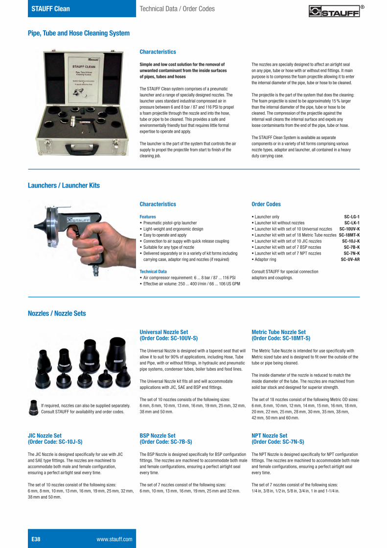
E38 www.stauff.com
STAUFF Clean Technical Data / Order Codes
Pipe, Tube and Hose Cleaning System
Characteristics
Simple and low cost solution for the removal of unwanted contaminant from the inside surfaces of pipes, tubes and hoses
The STAUFF Clean system comprises of a pneumatic launcher and a range of specially designed nozzles. The launcher uses standard industrial compressed air in pressure between 6 and 8 bar / 87 and 116 PSI to propel a foam projectile through the nozzle and into the hose, tube or pipe to be cleaned. This provides a safe and environmentally friendly tool that requires little formal expertise to operate and apply.
The launcher is the part of the system that controls the air supply to propel the projectile from start to finish of the cleaning job.
The nozzles are specially designed to affect an airtight seal on any pipe, tube or hose with or without end fittings. It main purpose is to compress the foam projectile allowing it to enter the internal diameter of the pipe, tube or hose to be cleaned.
The projectile is the part of the system that does the cleaning: The foam projectile is sized to be approximately 15 % larger than the internal diameter of the pipe, tube or hose to be cleaned. The compression of the projectile against the internal wall cleans the internal surface and expels any loose contaminants from the end of the pipe, tube or hose.
The STAUFF Clean System is available as separate components or in a variety of kit forms comprising various nozzle types, adaptor and launcher, all contained in a heavy duty carrying case.
Launchers / Launcher Kits
Characteristics
Features § Pneumatic pistol-grip launcher § Light-weight and ergonomic design § Easy to operate and apply § Connection to air suppy with quick release coupling § Suitable for any type of nozzle § Delivered separately or in a variety of kit forms including carrying case, adaptor ring and nozzles (if required)
Technical Data § Air compressor requirement: 6 ... 8 bar / 87 ... 116 PSI § Effective air volume: 250 ... 400 l/min / 66 ... 106 US GPM
Order Codes
§ Launcher only SC-LG-1 § Launcher kit without nozzles SC-LK-1 § Launcher kit with set of 10 Universal nozzles SC-10UV-K § Launcher kit with set of 18 Metric Tube nozzles SC-18MT-K § Launcher kit with set of 10 JIC nozzles SC-10J-K § Launcher kit with set of 7 BSP nozzles SC-7B-K § Launcher kit with set of 7 NPT nozzles SC-7N-K § Adaptor ring SC-UV-AR Consult STAUFF for special connection adaptors and couplings.
Nozzles / Nozzle Sets
Universal Nozzle Set (Order Code: SC-10UV-S) The Universal Nozzle is designed with a tapered seat that will allow it to suit for 90% of applications, including Hose, Tube and Pipe, with or without fittings, in hydraulic and pneumatic pipe systems, condenser tubes, boiler tubes and food lines. The Universal Nozzle kit fits all and will accommodate applications with JIC, SAE and BSP end fittings. The set of 10 nozzles consists of the following sizes: 6 mm, 8 mm, 10 mm, 13 mm, 16 mm, 19 mm, 25 mm, 32 mm, 38 mm and 50 mm.
Metric Tube Nozzle Set (Order Code: SC-18MT-S) The Metric Tube Nozzle is intended for use specifically with Metric sized tube and is designed to fit over the outside of the tube or pipe being cleaned. The inside diameter of the nozzle is reduced to match the inside diameter of the tube. The nozzles are machined from solid bar stock and designed for superior strength. The set of 18 nozzles consist of the following Metric OD sizes: 6 mm, 8 mm, 10 mm, 12 mm, 14 mm, 15 mm, 16 mm, 18 mm, 20 mm, 22 mm, 25 mm, 28 mm, 30 mm, 35 mm, 38 mm, 42 mm, 50 mm and 60 mm.
JIC Nozzle Set (Order Code: SC-10J-S) The JIC Nozzle is designed specifically for use with JIC and SAE type fittings. The nozzles are machined to accommodate both male and female configuration, ensuring a perfect airtight seal every time. The set of 10 nozzles consist of the following sizes: 6 mm, 8 mm, 10 mm, 13 mm, 16 mm, 19 mm, 25 mm, 32 mm, 38 mm and 50 mm.
BSP Nozzle Set (Order Code: SC-7B-S) The BSP Nozzle is designed specifically for BSP configuration fittings. The nozzles are machined to accommodate both male and female configurations, ensuring a perfect airtight seal every time. The set of 7 nozzles consist of the following sizes: 6 mm, 10 mm, 13 mm, 16 mm, 19 mm, 25 mm and 32 mm.
NPT Nozzle Set (Order Code: SC-7N-S) The NPT Nozzle is designed specifically for NPT configuration fittings. The nozzles are machined to accommodate both male and female configurations, ensuring a perfect airtight seal every time. The set of 7 nozzles consist of the following sizes: 1/4 in, 3/8 in, 1/2 in, 5/8 in, 3/4 in, 1 in and 1-1/4 in.
If required, nozzles can also be supplied separately. Consult STAUFF for availability and order codes.
STAUFF ONE - Hydraulic Accessories - English.indd 38 23.11.2013 12:34:14
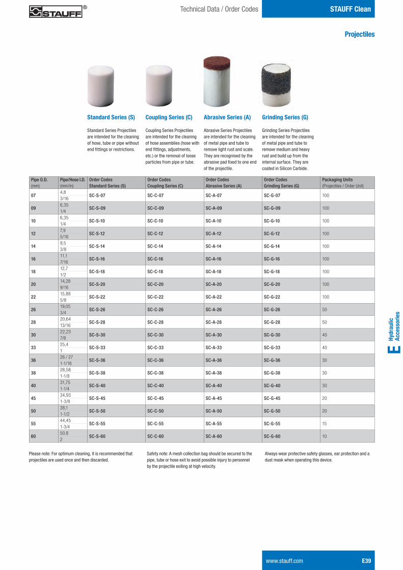
Hydr
aulic
Ac
cess
orie
sE
STAUFF Clean
www.stauff.com E39
Technical Data / Order Codes
Projectiles
Standard Series (S) Standard Series Projectiles are intended for the cleaning of hose, tube or pipe without end fittings or restrictions.
Coupling Series (C) Coupling Series Projectiles are intended for the cleaning of hose assemblies (hose with end fittings, adjustments, etc.) or the removal of loose particles from pipe or tube.
Abrasive Series (A) Abrasive Series Projectiles are intended for the cleaning of metal pipe and tube to remove light rust and scale. They are recognised by the abrasive pad fixed to one end of the projectile.
Grinding Series (G) Grinding Series Projectiles are intended for the cleaning of metal pipe and tube to remove medium and heavy rust and build up from the internal surface. They are coated in Silicon Carbide.
Pipe O.D. Pipe/Hose I.D. Order Codes Order Codes Order Codes Order Codes Packaging Units(mm) (mm/in) Standard Series (S) Coupling Series (C) Abrasive Series (A) Grinding Series (G) (Projectiles / Order Unit)
074,8
SC-S-07 SC-C-07 SC-A-07 SC-G-07 1003/16
096,35
SC-S-09 SC-C-09 SC-A-09 SC-G-09 1001/4
106,35
SC-S-10 SC-C-10 SC-A-10 SC-G-10 1001/4
127,9
SC-S-12 SC-C-12 SC-A-12 SC-G-12 1005/16
149,5
SC-S-14 SC-C-14 SC-A-14 SC-G-14 1003/8
1611,1
SC-S-16 SC-C-16 SC-A-16 SC-G-16 1007/16
1812,7
SC-S-18 SC-C-18 SC-A-18 SC-G-18 1001/2
2014,28
SC-S-20 SC-C-20 SC-A-20 SC-G-20 1009/16
2215,88
SC-S-22 SC-C-22 SC-A-22 SC-G-22 1005/8
2619,05
SC-S-26 SC-C-26 SC-A-26 SC-G-26 503/4
2820,64
SC-S-28 SC-C-28 SC-A-28 SC-G-28 5013/16
3022,23
SC-S-30 SC-C-30 SC-A-30 SC-G-30 407/8
3325,4
SC-S-33 SC-C-33 SC-A-33 SC-G-33 401
3626 / 27
SC-S-36 SC-C-36 SC-A-36 SC-G-36 301-1/16
3828,58
SC-S-38 SC-C-38 SC-A-38 SC-G-38 301-1/8
4031,75
SC-S-40 SC-C-40 SC-A-40 SC-G-40 301-1/4
4534,93
SC-S-45 SC-C-45 SC-A-45 SC-G-45 201-3/8
5038,1
SC-S-50 SC-C-50 SC-A-50 SC-G-50 201-1/2
5544,45
SC-S-55 SC-C-55 SC-A-55 SC-G-55 151-3/4
6050,8
SC-S-60 SC-C-60 SC-A-60 SC-G-60 102
Please note: For optimum cleaning, it is recommended that projectiles are used once and then discarded.
Safety note: A mesh collection bag should be secured to the pipe, tube or hose exit to avoid possible injury to personnel by the projectile exiting at high velocity.
Always wear protective safety glasses, ear protection and a dust mask when operating this device.
STAUFF ONE - Hydraulic Accessories - English.indd 39 23.11.2013 12:34:15

STAUFF ONE - Hydraulic Accessories - English.indd 40 23.11.2013 12:34:15


![Lecture 31 ACCESSORIES USED IN FLUID POWER SYSTEMS [CONTINUED]nptel.ac.in/courses/112106175/Module 3/Lecture 31.pdf · Lecture 31 ACCESSORIES USED IN FLUID POWER SYSTEMS [CONTINUED]](https://img.pdfslide.net/doc/110x75/5a9e43197f8b9a36788d644f/lecture-31-accessories-used-in-fluid-power-systems-continuednptelacincourses112106175module.jpg)


![Lecture 31 ACCESSORIES USED IN FLUID POWER SYSTEMS … · ACCESSORIES USED IN FLUID POWER SYSTEMS [CONTINUED] 1.6 Filters and Strainers For proper operation and long service life](https://img.pdfslide.net/doc/110x75/5f4e8d2703fc83692e6c102e/lecture-31-accessories-used-in-fluid-power-systems-accessories-used-in-fluid-power.jpg)