Embed Size (px)
Citation preview
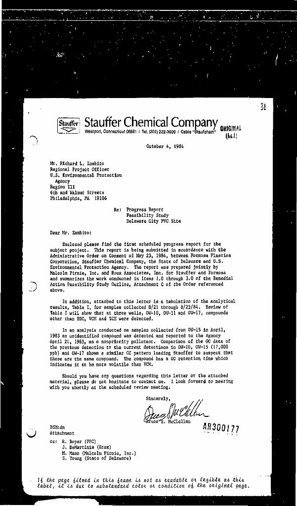
Stauffer Chemical CompanyJ Weatporl, Connecticut 06681 ( Tel, (203) 222-3000 / Cable "Slaufchem"
October 4, 1984
Mr, Richard L, ZambldoRegional Project OfficerU.S. Environmental ProtectionAgency
Region HI6ch and Walnut StreecaPhiladelphia, PA 19106
Re: Progress ReportFeasibility StudyDelaware City PVC Site
Dear Mr, Zambitoi
Enclosed please find the first scheduled progress report for thesubject project, This report Is being submitted in accordance with theAdministrative Order on Consent of May 23, 1984, between Formosa PlasticsCorporation, Stauffer Chemical Company, the State of Delaware and U.S.Environmental Protection Agency. The report was prepared jointly byMalcolm Pirnle, Inc. and Roux Associates, Inc. for Stauffer and Formosaand summarizes the work conducted In Items 1,0 through 3,0 of the RemedialAction Feasibility Study Outline, Attachment C of the Order referencedabove.
In addition, attached to this letter is a tabulation of the analyticalresults, Table I, for samples collected 8/21 through 8/23/84. Review ofTable I will show that at three wells, OW-10, OW-11 and OW-17, compoundsother than EDC, VCM and TCE were detected,
In an analysis conducted on samples collected from OW-15 in April,1983 an unidentified compound was detected and reported to the AgencyApril 21, 1983, as a nonpriorlty pollutant. Comparison of the GC data ofthe previous detection to the current detections in OW-10, OW-15 (17,000ppb) and OW-17 shows a similar CC pattern leading Stauffer to suspect thatthese are the same compound, The compound has a GC retention time whichIndicates it to be more volatile than VCM,
Should you have any questions regarding this letter or the attachedmaterial, please do not hesitate to contact me. I look forward to meetingwith you shortly at the scheduled review meeting,
•U-\_
flR300J77Attachment ' - - • .'.•'.cos R, Boyer (FPC)
J. DeMartlnls (Roux)M, Mann (Malcolm Pirnle, Inc.)S, Young (State of Delaware)
the. pjage dUmud in thi* tf/iame *•*> not M /m.ada,bf.e. on legible a-iit i* dm to AubAtanda/id acton, on. condition od the. o/iiginat page.

TABLE 1
***Analysis of Delaware City Plant Well Water For Viny1; ChlorideMonomer (VCM), 1,2-Dichloroethane (EDC), and Trichloroethylene (TCE)
Samples collected 8/21 - 8/23/84Samples analyzed 8/24 - 8/31/84
Concentration (ppb)
• VCM EDC TCJ Other Compounds' *ND **Det ND ND
310 1600 13 ND?tfc 23° * One at 100 ppb250 40 4 Three at 17,000,
„,, ,, 50, and 25 ppbOW-13 ND ND 4 NDOW-14 ' , ND ND 9 ND°W-16 ND ND Det ND°JJ-" 210 3400 15 one at 3,400 ppbOW-17A « . ND Det Det ND >°°W-18 ND ND ND NDOW-19 • ND ND ND ND°W-22 ND . ND ND ND"OW-28 ND ND 15 ND°°W-29 ND ND ND ' ND°W-30 50 1100 Det ND°W-31 ND ND 7 ND°OW~32 ND ND ND ND°W-33 ND ND ND ND
Lower Limito f Detection 1 1 1 1 0
»
QA spikes at 10 ppb(Average » recovery from.duplicate analysis) • 1054 93% 944
0 - samples split with EPA's contractor, NUS.*ND - Not detected.
**Det- Detected below the lower limit of ouantitation = 3 ppb.- Analysis by purge and trap gas chromatography with flamelonization detection.
o
Id the. page dimmed in thi* </iame i* not a* wadable. 01 iiQibtt a^ thit>tabe.t, it i& due to AubAtandaid toton on condition of, the. o/ugwat page.

CON5ULTINQ OnOUND.WATER GEOLOGISTSnouxAMocunvsMc50 NORTH NEW YORK AVENUEpo BOX 2W, HUNTINQTON, NEW YORK 11749 eie 673.4921POBOXI90,FAIRFIEID,CONNECTICUT06530 203 2M-H33
September 27, 1984
Mr. Bruce McClellanStauffer Chemical CompanyNyala Farm RoadHestport, CT 06881
Dear Mr. McClellan:
Enclosed please find a formal report summarizing the workconducted in 1.0 through 3.0 of the Remedial ActionFeasibility Study for the Delaware City Site. This reporthas been prepared jointly by Malcolm Pirnle, Inc. and RouxAssociates. Included are a summary of the site conditions,statement of response objectives and criteria evaluationprocess, and remedial options selected for furtherevaluation.Should you have any questions on any of the above, please donot hesitate to contact us.
Sincerely yours,Malcolm Pirnie, Inc.
Michael J. MannManager, Hazardous Waste
Roux Associates Inc.
James DeMartlnisSenior Hydrogeologist
cc. Mr. Robert Boyer, FPCMr. Mel Beers, SCC
AR300179
If, the. page (,itme.d in thiA fl/iama it> not a.4 /iead«6£e on le.gibte. O.A thi*it i* due to AubAtandaid co£o/i on condition oi the. oniginat. page.

ORIGINAL' <Red)
1.0 PROJECT UPDATE
A finding of EDC and VCM in a domestic supply well on
Stauffer Chemical Company property on April 20, 1982
prompted an investigation of the source of these
compounds, their impact on the Columbia aquifer, and
their potential impact on other nearby wells. A detailed
hydrogeologic Investigation including monitoring well
installation, a resistivity survey and well-sampling was
conducted and results are described in the Roux
Associates, Inc. report dated 2/4/83. The source(s) ofthe EDC and VCM to the ground water and the limits of
EDC/VCM in the Columbia aquifer were identified and are
specifically designated in the subsequent Administrative
Order of Consent signed by Stauffer Chemical Company,
Formosa Plastics Corporation Delaware, DNREC and EPA on
May 23, 1984.
1.1 Additional Monitoring Well Installation
After the submlttal of the 2/4/83 report, EDC and VCM
were detected in the Foraker Getty and Stapleford
Chevrolet wells south of the mapped plume area. TwoflR300180
monitoring wells, OW-30 and OW-31, were Installed to
determine if these occurrences were related to the plume. oROUX ASSOCIATES INC
U the. page dimmed in thit d/iame i& not M nudable. on. tigible. O.A tki*(.a.be.1, it it> due. to AubAtandand zoton. on. aondition od the. oniginat page..

1 At this time two additional wells, OW-32 and OW-33, wereORIGINAL
also installed to better define the northern teirmiangd^f
the plume. The analysis of ground-water samples from the
four wells did not show EDC or VCM. It was concluded
that the EDC/VCM found in the two domestic wells was a
slug which became detached from the main plume, prior to
discharge into Dragon Run.
1.2 Existing Site Conditions
A water table map compiled from data collected on April
10, 1984 is shown on Figure 1. Stauffer has routinely
collected water-level data on a regular basis through
.'.J 1983-1984 (Table 1). Figure 1 is a representative water
table map. The configuration of the water table has not
varied significantly during this period of time.
Figure 1 shows a mound in the water table under the
western portion of the PVC plant property. The highest
water level in this mound was recorded at OW-11, east of
the identified source(s). This level is probably caused
by water losses at the plant (fire water ponds, cooling
water towers) upgradlent of the identified source area.
Ground water flows from the area of this mound to the
northwest, west and southwest. Ground water containi/jc o n Q i g I
EDC and VCM is flowing west from the area of the PVC
ROUX ASSOCIATES INC
If, the. page (,itme.d in thU (,/iame. i& not a* nudabte. on Itgibte. a.*, thi*tabe.ll, it i& due to AubAtandand noton on. condition of, the. oniginal page..

*«,"\.,
3|j t/ie page ij^^med in thi* iname. i* not a,4 /leadab^e OA ^tabe.1, it it, due to AubAtandand coton on condition of, the. original page..

*w l/fl/ll«r ""in »<»/>» I
a ' «ui . nil
ORIGINAL
:lJ/!/lLf'I ufff
A* if I 11.0 • «,$• *).««KMV i •*«•'•«.7f!
w,
«',!> YU» *».'• «>,(» *?,'.»,»• !»,»» It, I* »•••!» y/,j
vi,«f
17, <fCM- 0 W.I) i 1W,« i W.7f
.Ht.lt 1(,» H.tl lil.tt U7.ll
;»,* I9,fj> 11.99 sits <te.t7n.•n !•.,.« «,|, ,?PIT |»t,
W-H 3t.S? "•«; 3'>'* X*. . «f.5 j 31>H Wil *?.to lift
37,«3, r>,9$\ 3(,Si . W.0t Jj.75 VF,t/ f'f**' ?'.«•!»,$« 37.f8 ??.»? 3<,y/ 77.V/ J?,W 39,«*
37.4* jf.fi u.ft n.u j?,f/
;| 17,50, wn y>.<& , it>.
"•"•Hi 3'- |f'»,»
w,n\ w,ft' w.fo'n7{' 'H.tu • v.t?V.W if.ee y.to ,J?,w3jf.5S 37,17
5P./7}1,9S
I(! *fee page (,itme.d in thit> iname. it not a* wadabte. on ttgibte. a* thi*tab*.t, it iA due. to AubAtandand colon on condition of, the. oniginat page..

3ORIGINAL(Rod)
impoundments. Ground water flowing to the northwest
toward OW-5 turns in a northerly direction (roughly
parallel to Route 13) and flows toward Red Lion Creek.
Ground water flowing from the PVC plant toward OW-16
turns in a southerly direction and flows to Dragon Run.
The sediments are more permeable and the gradient is
steeper to the south especially near the tributary to
Dragon Run. This is indicating that a greater amount of
ground water is discharging into Dragon Run.
Figure 2 shows the EDC/VCM plume as taken from Roux
Associates' report "Hydrogeology and Ground-water
Conditions" dated February 4, 1983. Values of EDC and
VCM from the most recent round of sampling (August 1984)
are plotted on this figure to compare with the limits of
the plume identified in the Roux Associates report and in
the Administrative Order of Consent dated May 23, 1984.
Comparison of this figure, subsequent sampling results
and the latest results indicate:
(1) The ground-water sample from ow-30 shows 1,100 ppb
EDC and 50 ppb VCM. This finding is consistent with
ground-water flow directions mapped over the past
year. This well showed no EDC or VCM the first (and
GBOUXASSOCUTESINC AR300I81*
If, the. page. f,itme.d in thiA f,name. iA not aA ne.adabte. on te.gibt.e. aA thiAlabe.t, it iA due. to AubAtandand coton on condition of, the. oniginat page..

If, the. page, litme.d in thiA f,name. iA not aA ne.adabte. on te.gibte. aA thiAtabe.t, it iA due. to AubAtandand coton on condition of, the. oniginat page..

4 ORIGINAL(Rod)
only) time it was sampled. This finding as well as
previous findings in the Foraker Getty and /—\
Stapleford wells appear to represent a slug which
became detached from the plume prior to discharging
into Dragon Run.
(2) It appears that the plume has stabilized in the
northerly direction. Despite findings of EDC and
VCM in OW-5 from the inception of the project, OW-
33, OW-32 and OW-22 have never shown EDC or VCM.
Sediments in the Columbia aquifer in this area are
significantly less permeable than those to the south
and the gradient is flatter (Figure 1).
(3) No wells west of Route 13 have ever shown EDC or VCM f '\
(OW-33, OW-29, OW-31, OW-28 in the most sampling -
all others in previous samplings).
1.3 Determination of Seepage Velocity from the Columbia
Aquifer through the Merchantville Aquitard into the
Magothy.
During the drilling of OW-31, OW-32 and OW-33,
undisturbed samples of the Merchantville Formation were
collected and analyzed for permeability. The three
samples had permeabilities of 8.3 x 10"8, 6.8 x 10"7 and
1.8 x 10"B cm/sec, respectively.
ROUXASSOCIATESINC AR300I86
I(S the. page. (,itme.d in thiA f,name. iA not aA ne.adabte. on te.gibte. aA thiAtabe.t, it iA due. to AubAtandand coton on condition of, the. oniginat page..

ORIGINAL(Rod)
The Darcy Equation can be used to calculate the average
seepage velocity of a mass of water progressing through
the pore spaces of the Merchantville as follows;
Ki
where Vs = seepage velocity
K = permeability of the Merchantville
i = hydraulic gradient under which seepage occurs
ne B effective porosity of the Merchantville
K has been determined by laboratory analysis on
undisturbed Mechantville samples and a value of 1 x 10"8
cm/sec will be substituted into the above equation.
'.} The hydraulic gradient is the head difference between the
Columbia and Magothy aquifers (h) divided by the
thickness of the Merchantville (1). The head difference
is estimated at 25 feet as the piezometric surface of the
Magothy Is estimated at 15-20 feet above mean sea level
(Sundstrom and Pickett, 1971 J.1 This is probably a high
number. The thickness of the Merchantville is assumed to
be 20 feet (based on test boring data) though it is
probably thicker under most areas of the plume.
The effective porosity of the Merchantville is estimated
at 30 percent or 0.30.
•'•The Availability of Ground Water in New Castle County
ROUXASSOCtATESINC flR300|87
If, the, page, ditmd in thiA {name. iA not aA ne.adabte. on te.gibte. aA thiAtabe.t, it iA due to AubAtandand coton on condition of, the. oniginai. page.,

ORIGINAL(Red)
Substituting these values into the above equation;
(10"8 cm/sec) (1.25)Vs » 0.30
Vs = 4.2 x 10~8 cm/sec or
Vs » 1.3 cm/year
Since the thickness of the Merchantville is approximately
20 feet or 609.6 cm, It would take 469 years for ground
water in the Columbia aquifer to penetrate the
Merchantville and enter the Magothy.
1.4 Installation of 2" Diameter Observation Wells
During the week of August 13-17, 1984, eleven two-inch
diameter observation wells were installed at the Delaware
City Site by H.P. Drilling of National Park, N.J. These
wells were drilled and installed in accordance with
Attachment I of the Administrative Order of Consent underthe supervision of a geologist from Roux Associates.
Locations are shown on Figure 3 and construction details
are given in Table 2.
One soil sample was collected from one piezometer boring
at each pumping well location. A sieve analysis and a
determination of organic carbon content is presently
being run on each sample to help evaluate rate of
migration of ECC/VCM in the aquifer.
nR300168
If, the. p^age f,itme.d in thiA f,name. iA not aA ne.ada.bte. on te.gibte. aA thiAtabit, it iA due to AubAtandand colon on condition of, the. oniginat page..

ORIGINAL(Red)I I I II I I I I III / II / I M M 1 II I I I /MM I M M )
o:
J f-t\ AV /A*V- ©OuMSfw
60'/
o flR3Q0189
I(! t/ie page dimmed in thiA f,name. iA not aA nzadabte. on le.gibte. aA thiAtabet, it iA due. to AubAtandand coton on condition of, the. oniginat page..

ORIGINAL(Red)
a•H
X in in in oo co r> co eo0 • . . ( * ) • • . 1 . . .M f l N H H . N M H N H H H
aH 8 «• M Hfr< h H in mHUM 01 . . ui . . . JJj .823 c m in • in N N . I NB f l , 0 i « H > . . M I
t l H N O O C O M * O O I > U ) ( 0in i i - i t> i i . i
g - . i m m vo inM^ 0 in 00 00 H «r
H {/} H H H 01 in
DiR•H
IA
H N O I ' i n W f ' C O o i H HI I I I I I I I I I I
If, the. page. f,itme.d in thiA f,name. iA not aA ne.ada.bte. on tagibte. aA thiAtabe.1, it iA due. to AubAtandand coton on condition of, the. oniginat page..

7 ORIGINAL(Red)
At the completion of drilling all wells were developed by
^\ surging with air. This was done to remove any drilling
fluids that might still be in the formation and to insurea good connection between the aquifer and the well
screen.
1.5 Specific Capacity Testing
Selected monitoring wells, both inside and outside of the
plume, were test pumped for fifteen minutes at 50, 30,
and 10 gallons per minute respectively. Water levels
were measured regularly prior to, during and after
pumpage. It was determined that none of the wells tested
could sustain 50 gpm over an extended period of time
'_) (greater than 15 minutes). Some wells could be pumped at
30 gpm but water levels would decline into the screen
zone with time.
OW-12, OW-15 and OW-7 had specific capacities of 1.32,
2.01, and 1.42 gpm per foot of drawdown respectively.
Other wells tested and their specific capacities are as
follows: OW-1 (3.53), OW-2 (2.39), OW-6 (1.56), OW-8
(3.68), OW-9 (0.70), OW-10 (3.02), OW-11 (1.00), OW-16
(0.80), OW-17 (5.15), OW-28 (5.38) and OW-29 (7.52).
This demonstrated that OW-12, OW-7, and OW-15 could be
pumped at between 10 and 15 gpm for the long term pumping
tests.J AR300I9
ROUX ASSOCIATES INC
I! the. page. f,itme.d in thiA f,name. iA not aA ne.adabte. on te.gibte. aA thiAtabe.t, it iA due. to AubAtandand colon on condition of, the. oniginal page.,

ORIGINAL
1.6 Pre-Pump and Pump Tests
To determine aquifer hydraulic parameters necessary for
design of any potential ground-water Intercept system,
the following pump test program was conducted accordingto Attachment 1 of the Administrative Order of Consent.
During the week of August 20, 1984 a pre-pump test was
run on OW-12 and OW-15. The purpose of the pre-pump
tests was to make sure that drawdown could be measured in
the surrounding 2-inch observation wells at the allowed
pumping rate. Wells OW-12 and OW-15 were pumped for
approximately 2-3 hours each using a submersible pump.
Water levels were measured in the 2-inch observation
wells. All observation wells (with the exception of the
water table piezometer P-4) showed drawdown.
On August 29-30, 1984 a pump test was conducted on OW-12.
For this test, Stevens Type F water-level recorders wereset up on three of the 2-inch diameter observation wells;
P-ll, P-9, and P-5. Water levels in the remainder of the
wells and the pumping well were measured by using
electronic probes and steel tapes.
e
HR30019Z
ROUX ASSOCIATES INC
If, the. page denied in thiA f,name. iA not U.A ne.ada.bte. on legible. aA thiAlabe.1, it iA due to AubAtandand coton on condition of, the. oniginat page..

ORIGINAL(Red)
TABLE 3- Pumping Tests - Frequency of Readings
Elapsed Time (minutes) Frequency of Measurements
0-5 Every 30 seconds
5 - 1 0 Every minute
10 - 30 Every 2 minutes30 - 60 Every 5 minutes
60 - 120 Every 10 minutes
120 - 180 Every 20 minutes
180 - 360 Every 30 minutes
360 Every hour
ROUX ASSOCIATES INC
RR3Q0193
If, the. page. f,ilmd in thiA (,name. iA not aA ne.adabte. on legible. aA thiAlabe.1, it iA due to AubAtandand colon on condition of, the oniginal page..

ORIGINAL(Rod)
o)
,
H the page (,itme.d in thiA f,name. iA not aA neadabte. on legible. aA thiAlatal, it iA due. to AubAtandand colon on condition of, the anginal page.

fable 4 PUMPING TEST FORMH NORTH NEW VORK AVENUEI'D L'OX !M, MUN1INOKW, NCW VOftK WO
.f-fts tl am nto-IE. infLt.nu *if>o' IM) A M \y\~Gt c*'j .1——OF2-
OAT' ft'Tfl-y*- ———— M,r.r.Mf.- ... - ———— H •', ABOVE O.S,.-LJL_ W.L, MtAS, »/ M-Jgoia*M,P, - « '
r_2l! ——— PUMPINC/m.,0 ' . Qj£.l£> ___ ORIMCE _____ BMTMBB t,i,r.\f -C oo I• '
/J^DRAWOOWH —.RECOVERY _ UOCATION 3KETCH T
TIMErtnllci
t HMD WET D.T.W.MANO-METER
WATERTEMP, REMARK
. -i. •o_'•2.19
3 i??.L. —Aoi
I'.1*?_. _.t6Xt/u.'<-t——i -'H•—~ a>". i» a?, to
£9.8330-. li
8a-.lt,
.__.J2.!£°, J9.es12*84
—— Zifjfto-
99,8?09,
iu'.P 1
iu.'o 1
IfO'.'tl
3o-,o'7 29, »J
Mfiil
So -.ofc
' 2. aSo-.o-i
91.91
tlo-.o3o-.ol
3O.OJ
3o.o|:.=:»li 2,76
r-. —A^s-*ia£f?i:.
IO.S
/g.s10,5
/o.SAR300I95
5-70
5-70
n the. page. f,itme.d in thiA rf/iame iA not aA ne.adable. on le.gibte. a* thiAlabe.1, it iA due. to AubAtandand colon on condition of, the. ontgwal page..

'&Uc4 L&wr) PUMPING TEST FORMMNGNTHNEWVOWAVENUS ' *• 'PO BOX Mt.HUNTINOTON, NEW YORK IIM3 ORIGINAL
u/rn a<M-)Z
F ^ -l 'f!1],. "»
'JL DIIUI
9CRI
• DRAWDOWN
TIME ,r."1^.pcto.'Ol/O.'OO«y.pa
TTD.'O*Jflo.'o/3Vk',ol1S««I8',«l
• ;•.•.!?SlC.lO(Sel.»lG£l.0fli/fl!'Wa.si".;. ,M
C.I/ 1.1 '/IIM.ra•'fl.l?1.' !..!•'J.)l.';.<
1 If J.IlSo3.
i: ••
/Sic;..'"•/iKoc,'•''((• 11/rfPifcffSL9WCL(gCQ
O/
HELD
,1
>INO WELLru
M.P. ELC u0
Hf.A!
.. i««• »,*,- , W,l,. MF« *'
MEAS,
naitif.t WMTI
RECOVERY _ LOCATION SKETCH ™T
WET
•
D.T.W,
*..c'*a».oTi9.O2,
I0i 023a. 033».oT.3«.otO.ffO
?0/«0•iJ.o's30. »•/W.o?.e
5o.llaq^g'.•.I!:'..v3? , ,/^3A I1/30, 1'/3n /i'':C,lC7.1.K'iw./72c . |f/V.O•_c...v'. a. '».''.
3o./.i|o.-to£.',«•30. n10 'i U3o \t,tO.lO
,2,71?i7/?.?(?3,703. 713j >oJ?. ?£2, tj?i<ff2.7/?. 723.753' 73,79Zi£&2-7?3,fl?,52J.W3i9i?, 633if45,545. Si"?, 873, 9/3. 9/2.?j3, 23.S??,f9.S5
a.-i'3,^1.3,.?5
f
MANO-METER
BY p,
.»
T»BT
run
Q
/0.75la.TS10,510,?10,710.910, S/o>t?//.2/0,7/O.fi/0.3/O.J/i). ?J
10,910,110,6
I/O./I/O.//O,//0, 5jto s./AS//,sJr//i 35/U,f/0,5
'7'/O.1?/d. D/f,Z/*, £s/0.3
WATERTEKP.570
5"^ °?7°57°5u°Sf65.70-5"6 °Sg185£ •S("'ft6571157051 oS-l*£6"5& 65S °SS<>54"n* * ^j
C£ 0
s?°?f °S>' "-TA*JTi"5" fls*/f °?7tf5-705-7°5-7 o56 »
-fl*£
REMARKS
'ff-fM "" " i 'i-'i.'<-3 .•, •/ <-
'v... •1
1
i
H *fce page rf^med ^K t(i*4 (S/iame ^ not aA ne.adable. on te.gible. aA thiAlabe.1, it iA due to AubAtandand colon on condition of, the. oniginat page..
(lied)
"~> A discharge pit was dug by a backhoe approximately midway
between OW-12 and OW-15 (Figure 3). This pit was dug to
accomodate the discharge from these two wells during the
course of the pump test. .
During the course of the pump test, water levels were
measured in wells on a regular basis (Table 3) and the
recorders were ticked and the time written directly on
the chart. Water levels were also taken in OW-15 during
the test as this well used as a background well. A raingauge was set up on-site to measure any precipitation
during the tests. However, no rainfall occurred.
• ) Prior to the pump test, water levels were taken for
several days in OW-12, the surrounding observation wells,
and OW-15 and these levels used for pre-pump test data. .<•
The discharge rate was measured frequently during the
test and was constant at 10.3 gpm. The temperature of
the discharge was also recorded. All data was put on
pump test forms and plotted on graph paper In the field
(see Figure 4 and Table 4). The test was shut down after33 hours because sufficient data to analyze and interpret
were collected. At the completion of the pump test a 100
minute recovery test was conducted.
flR300!97
ROOK ASSOCIATES INC
I(S the. page. (,ilme.d in thiA {name. iA not aA ne.ado.ble. on legible. aA thiAlabe.1, it iA due to AubAtandand colon on condition of, the. oniginal page..

10
On September 5-6, 1984 a 24 hour pump test was conducted
on OW-15 using the same protocols as OW-12. Stevens x-^
water-level recorders were set up on P-7 and P-6 for this
test. OW-12 was used as the background well during the
course of the test. The discharge rate for thi* test was
found to be 12.8 pgm. At the completion of the test a
100 minute recovery test was performed.
OW-7 was pump tested on August 21, 1984 using a
submersible pump. Before starting the pump, pre-test
water levels were measured in OW-7 with the pump in the
well and also in the surrounding 2 inch observation
wells. During the course of the pump test, water levels
were taken regularly in the observation wells and the
pumping well. This data was recorded on pump test forms ,'
and plotted on graph paper in the field. The rate of
discharge was checked regularly and remained constant at
12 gpm throughout the test. At the end of the pump test
(t B 8.5 hours) the recovery of water levels were
measured for 100 minutes.
1.7 Additional Work
The following additional investigative work not included
as part of work outlined in Attachment B of the
Administrative Order of Consent will be conducted.
AR300I98G
ROUXASSOdATUINC
Ili the. page. f,ilme.d in thiA (,nam<t. iA not aA ne.adabte on legible. aA thiAlabel, it iA due. to AubAtandand colon on condition of, the. oniginat page..

11ORIGINAL(Red)
A test pit investigation will be performed in the former
PVC resin storage pit as identified in Attachment fl of
the Administrative Order of Consent. The purpose of this
investigation is to determine if any residues of EDC or
VCM remain in this area. The test pits will be excavated
by a conventional rubber-tired backhoe to four feet into
natural deposits or a maximum depth of eight feet. A
geologist will visually inspect and log test pits in this
area and collect selected soil samples for EDC/VCH
analysis. It is envisioned that ten test pits will be
excavated.
RR30019?
ROUX ASSOCIATES INC
If, the. page. f,ilme.d in thiA f,name. iA not aA neadabte. on legible aAlabe.1, it iA due. to AubAtandand colon on condition of, the. oniginal page..

12 ORIGINAL(Red)
2.0 REMEDIAL RESPONSE OBJECTIVES AND CRITERIA FOR
EVALUATION OF ALTERNATIVES
The general objective of this remedial response is to
effectively mitigate or eliminate damage to, and provide
adequate protection of public health, welfare, and theenvironment from the ground-water contamination that has
been identified and discussed in the report onHydrogeology and Ground-Water Conditions at the DelawareCity Site submitted by Roux Associates, Inc., February 4,
1983.
2.1 Objectives and Site Specific Goals
Specific objectives have been developed for this Site
which are consistent with the general remedial response
objective. These site specific objectives are divided
Into two categories: source abatement and mitigation of
the existing plume of contaminated ground water.
A) Source Abatement
Development of cost-effective method(s) for eliminatingthe continued release of EDC, VCM and TCE to the ground
water from the sources identified in the Administrative « ~„ n n
Order of Consent dated May 23, 1984.
ROUX ASSOCIATES INC
I(( the. page. f,ilme.d in thiA (,name. iA not aA ne.adable. on le.gible. aA thiAlabel, it iA due to AubAtandand colon on condition of, the. oniginat page..

13
B) Mitigation of Existing Plume of Contaminated Ground Water
1) Development of a cost-effective method(s) for
eliminating the potential direct exposure via human
consumption for those receptors which have previously
been identified as being impacted or have the
potential to be impacted by the existing ground-water
plume.
2) Development of a cost-effective method(s) to ensure
natural or artificial containment and/or cleansing of
the existing ground-water plume.
2.2 Evaluation of Criteria
In an effort to establish a means of evaluating the
effectiveness of developed remedial alternatives, Section
300.68(h) of the National Contingency Plan (NCP) was
reviewed. In accordance with the NCP, the following
criteria were selected and weighed in order of importance
to evaluate the effectiveness of the developed
alternatives:
(1) Long term reliability(2) Implementability
(3) Long and short term environmental impacts
(4) Operation and maintenance requiremenlftn 0 U0 L U I
ROUX ASSOCIATES INC
If, the. page. f,ilme.d in thiA dname. iA not aA loadable, on le.gible. aA thiAlabe.1, it iA due to AubAtandand colon on condition of, the. oniginal page..

14 ORIGINAL(Red)
(5) Public acceptance
(6) Time to implement
(7) Worker/community safety
The remedial alternatives will be ranked using the matrix
approach as described in Chapter 3 of the EPA Final Draft
Guidance Document for the Preparation of Feasibility
Studies dated November 15, 1983 (Attachment I) with the
criteria described above. Weighting factors which
reflect the relative importance of the aforementioned
criteria will be assigned. The various technologies
which comprise each alternative will be evaluated
individually; after which an overall rating will be
determined for each alternative.
Cost estimates will be prepared for the top three
remedial alternatives in each area (source abatement and
ground-water plume mitigation).
RR300202c
ROUX ASSOCIATES INC
Jii the. page. (,ilme.d in thiA {name. iA not aA niadable, on legible. aA thiAlabe.1, it iA due to AubAtandand colon on condition of, the. oniginal page..

15
ORIGINAL(M)
3.0 INITIAL SCREENING OF GENERAL REMEDIAL OPTIONS
In accordance with the remedial objectives, two major
categories will be pursued in the development of a
general approach toward remedial action: source abatement
and ground-water plume abatement.
3.1 Source Abatement
The report by Roux Associates on the hydrogeology and
ground-water conditions at the Delaware City Site
indicated that the source(s) of EDC, VCM and TCE
contamination is located within the existing plant site.
Further investigation revealed five sources of EDC, VCM,
and TCE. These sources have been Identified in the
Administrative Order of Consent: off grade batch pit,
aeration lagoons, storm water reservoir, buried sludge
pits, and former PVC resin storage pit.
A site inspection was conducted by Malcolm Pirnie (August
16, 1984) in which the identified sources were inspected.
Past and present operating practices were reviewed with
Stauffer and Formosa personnel. Past and present
disposal practices are summarized by source as follows:
RR300203
ROUX ASSOCIATES INC
U the page. f,itme.d in thiA f,name iA not aA ne.adable. on te.gibte. aA thiAlabel, it iA due, to AubAtandand colon on condition of, the. oniginat page.

16 ORIGINALOff-Grade Batch Pit: An unlined earthen lagoon receives
wastewater from the S-l and S-2 production areas when the
wastewater sumps in these areas overflow. Solids are
deposited in this lagoon which must be periodically dug
out and disposed.
Aeration Lagoons: Two aeration lagoons with concrete
bottoms and gunite sides receive process wastewater for
treatment. Solids build up in these lagoons which must
be periodically excavated.
Storm Water Reservoir: The Storm Water Reservoir is used
for stormwater collection and occasionally receives
wastewater from the E-2 production area when the
wastewater sump overflows. *•"•
Buried Sludge Pits: Unlined pits were used to dispose of
solid off-grade PVC resin material and cleanouts of
sludge from the earthen lagoon. The pits have now been
capped with a PVC cover designed to prevent percolation
of rainwater.
Former PVC Resin Storage Pit: A former PVC resin storage
pit has been emptied and backfilled. This area will be
further investigated to determine if residual EDC/VCM
remains. This work will be accomplished during the week&R300201*
GROUX ASSOCIATES INC
If, the page. f,ilme.d in thiA (,natne iA not aA nmdabte. on legible. aA thiAlabel, it iA due. to AubAtandand colon on condition of, the. oniginal page..

17 ORIGINAL(Red)
'~> Potential remedial options were discussed with Stauffer
and Formosa personnel during the investigation. The
remedial options have been divided into four general
categories. These general options are described as
follows:
1. No Action: Current plant operations would continue.
No modification would be made to existing sources of
contamination.
2. Modification of Plant Operations: This general
option involves assessing how current plant
operations may be modified to limit the discharge of--s'J contaminants to the ground water. One such
modification is the reduction of EDC usage as a
cleaning solvent within the plant. Currently the
plant Is looking to eliminate EDC usage by year end
1984. Other modifications include preventing
spillage of both raw material and product and
preventing the overflow of process waste sumps.
3. Modification of Source Structures; This general
option involves evaluating how the sources of
contamination may be modified to limit further
emission of material. Such modifications include _RR300205lining the existing lagoons provided that a suitable
OROUX ASSOCIATES INC
Itf the. page. (,itme.d in thiA f,name. iA not aA neadable on legible. aA thiAlabel, it iA due to AubAtandand colon on condition of, the. oniginat page..

18ORIGINAL(Rstf)
liner material can be found. Also included would be /*»\
diking the product handling areas and wastewater
sumps to capture spills and overflows. Primary
clarification may be implemented prior to aeration to
centralize solids handling.
4. Removal of Sources: This general option involves
evaluating the effectiveness of removing existing
sources of contamination such ac the buried sludge
pits.
5. Use of Containment Structures: This option involves
evaluation of isolating and/or capping existings~-t.
sources of contamination. Feasible technologies that :'
fall under each remedial alternative will be
identified and screened.
3.2 Evaluation of Remedial Alternatives - Ground-Water
Plume
The purpose of the remedial alternative evaluation is to
use site specific data to identify any conditions which
may limit or enhance the use of specific remedial
technologies. The feasible remedial technologies that
are being screened include ground-water controls andAR300206
ROUX ASSOCIATES INC
U the page, filmed in thiA (,name iA not aA neadabte on legible aA thiAlabel, it iA due to AubAtandand colon on condition of, the oniginal page.

ORIGINAL(Rod)
plume management. The following remedial alternatives
are being evaluated in detail.
Ground-Water Withdrawal
The pump test data when interpreted will help evaluate
the feasibility of an interceptor well system. The
aquifer coefficients will enable an assessment of the
number, spacing and pumping rates of any wells that would
comprise such a system.
Ground-Water Treatment
Ground-water treatment may be required as part of any
'J plume containment option, depending upon the ultimate
disposal of the withdrawn ground water. Feasible
treatment technologies that will be screened include
biological, chemical and physical treatment, treatment
within the existing on-slte wastewater treatment facility
and treatment at a publicly owned treatment works (POTW).
Formosa Plastics Corporation, Delaware may be able to
utilize withdrawn ground water for their process water.
This will be evaluated.
flR300207ROUX ASSOCIATES INC
If, the page filmed in thiA f,name iA not aA neadabte. on legible. aA thiAlabel, it iA due to AubAtandand colon on condition oi the oniginal page.

20
ORIGINALGround-Water Plume Management ("et') x»s
%,!
The feasibility of plume management will also be
evaluated. The following Information will be obtained
and synthesized into this evaluation:
(a) An identification of all water supply wells in the
area and determination which may be threatened by
the plume if no interceptor well system is employed.
(b) A determination of the availability and costs of
providing alternative water supplies.
(c) A determination of probable future uses of lands
above the plume and in the path of the plume, and
the estimation of the probable effects the presence
of the plume will have on these uses.
(d) A determination of the potential discharge rates of
EDC/VCM in ground water into surface-water bodies
and calculations of dilution ratios and the
classification of these bodies.
(e) A determination of if, and how many more monitoring
wells will be needed beyond present plume boundaries
to evaluate long tern migration of the plume.
(f) An evaluation of the possibility of migration of
EDC/VCM through the underlying aquitard.
AR300208
ROUX ASSOCIATES INC
if, the page (,ilmed in thiA &name iA not aA neadabte on legible. aA thiAlabel, it iA due to AubAtandand colon on condition of, the oniginal page.

21
ORIGINAL(Rud)
Other Options Considered but Eliminated from Further
Evaluation
No Action - Ground Water - This alternative has been
evaluated and, is not considered feasible. Alternative
water sources have already been supplied to impacted
domestic well users.
- In-situ Permeable Treatment Beds to Treat all Ground
Water. The installation of activated carbon treatment
beds may not be effective in removing EDC and VCM. The
lateral extent of EDC/VCM and the greater saturated
thickness near Route 13 would make the installation and
maintenance of treatment beds difficult and costly.
In-situ Treatment of Ground Water. This technology has
been less used than other methods at sites so its
reliability factor is uncertain.
Complete Plume Containment by Slurry Wall: This
alternative would involve the installation of a slurry
wall to contain the plume. However, the area of the
plume is large and isolating the plume would eliminate a
significant portion of ground water in the Columbia
aquifer from future use.
AR300209
ROUX ASSOCIATES INC
If, the page f,ilmed in thiA f,name iA not aA neadable on legible aA thiAlabel, it iA due to AubAtandand colon on condition of, the oniginal page,

(M)
ATTACHMENT
AR3002IO
ROUX ASSOCIATES INC
I(! the page (joined AH thiA f,name iA not aA neadable on £eg^fa^e aA thiAlabel, it iA due to AubAtandand colon on condition of, the oniginal page.

(Red)
final Draft
GUIDANCE OHTEE PUPAWfilOH OF RASIBILI7Y STUDIES
Fraparad for:
U.S. ZHVIROHMIilTAL PROTECTION AGENCYMunicipal Environaantal Haaaarch laboratory
26 Wtie St. Cliir StrattCincinnati, Ohio
and
Offie* of Emergency and Raaidial Raepon§a401 H Strait, SH
(W.-546-B)Uaihington, D.C. 20460
Compilad \>jt
JUS ASSOCIATES8400 Haatpark .Driva
Melon, Virginia 22101
Fraparad by;
EnvironEnviromaantal Law Inatituta
1C?, Ineorporatadfia Aaaociatai,IIVS Corporation
Radian Corporation
i
1llovanber 15, 1983 AR 3002 I I
If, the page filmed in thiA (,name iA not aA neadabte on legible aA thiAlabel, it iA due to AubAtandand colon on condition of, the oniginal page.
ORIGINAL(Red)0
CHAPTER 3
TECHNICAL EVALUATION
One of the firat concerna of the detailed analyaii of altarnacivaiidentified In the acreening procaaa ia the determination that aufintadCachnoloflea are technically appropriate |lvan apecific eite condltiona.Section 300.68(1) of the NCP require* the following!
"(i) Detailed Analyaia of Alternative*
(1) A more detailed evaluation will be conducted of the Haltednuaber of alternative that reaaln after the Initialacteenlni... '
(2) The detailed analyil* of each alternative ihould Include;
(A) Refinement and apaciflcatlon of alternatlvaa 'In detail,with emphaala on the uia of eatabllahed technology;
(C) Evaluation in terna of engineering Implenentatlon, orconitructablllty;
(E) An analyai* of ... method* for mitigating I adventenvironmental] impact*...."
i • '
Each remedial alternative I* to be evaluated and rated relative to one anotherwith reapect to performance, reliability, Impleaentablllty and aafetyconiideratlon*. The DSS Manual, the Corpa of Engineer* Engineer Manual"Preliminary Cuidalina* for Selection and Deeign of Remedial Syatema forUncontrolled Raaardoua Wait* Sltea" (EC 1110-2-600), and the EFA publication"Handbook for Remedial Action at Waite Dlapoaal Site*" (EPA-625/6-82-006)provide Information and additional referencee which will aid the uier Inperforming the** detailed analyaea of alternative*, The reault* of theiaevaluitlona provide the relative technical faailbillty of remedial altar-native* that are included in the co«t-*ff*ctivenea* imagery evalua on, n o I 0
3-1
U the page f,itmed in thiA {name iA not aA neadable on legible aA thiAlabel, it iA due to AubAtandand colon on condition of, the oniginal page.

ORIGINAL(Red)
Element* of technical fallibility are diicuiaed below In aectiona 3.1 to 3.4and a auggeatad format for aummarising thai* evaluation* la pruented inlection 3,5.
3.1 PERTORHANCE
There are two aapact* of remedial action* thae determine the deelrabllltyon the baila of performance, theaa are: •ffectiveneea and uaaful life. Theeffictivenen of an alternative 1* the degree to which it will accompliih it*deaign objective. The uteful life 1* the length of time that the design levelof effictivenen can be maintained.
.3.1.1 Effeetlveneaa
The HCF dlatinguiihei aource-control ictivitlei from off-lit* activitie*ind the deelga objectlvei of remedial activitlei art generally developed Intheia teni. Fropoied remedial ttchnologln ihould be evaluated In terai ofthe ability to perform Intended functloni luch ai containment, diveralon, '
--v removal, deitruction, or treatment, Any apecial lit* or waate conditionchineterlitici which affect performance ihould be coniidered and the deilgntallond to accocaodata thoie condltloni. The evaluation alio naedi to con-ildir how effectively the component technologlei can be Integrated to providean overall effective alternative. Where poailble, deilgn ipaclflcatloniihould be developed In order to eniure eftactlv* performance, Thiaa apecifi-cationi ihould recommend, where applicable, ASTM, AASHO, or other approprliteengineering itindarda. Of courie, itandarda are not available for allapplleitiona at haiardoui waite iltei; in theie initance* performanceipicificatloni baaed on beat engineering judgement nuit be developed,
3.1.2 nieful life
Moat remedial engineering technologiei, with perhapa the exception ofremoval or deitruction, deteriorate, For tome tichnologlei, thi eventualdeterioration can be lomiwhat ameliorated through proper oparatloni andmaintenance. However, eventually the technology may require replacement. Inother Initancei no maintenance la poiaibl* and replacement it nquired after acertain length of time. Eech alternativ* remedial action ihould be evaluated
ii ~"~~™"""~™""-™-. fc ^\J
3-2
AR3002I3If, the page filmed in thiA (,name iA not aA neadabte on legible aA thiAlabel, it iA due to AubAtandand colon on condition of, the oniginal page,

ORIGINAI(Rtd)
In termi of the projected iirvlce llvei of th* technologiei of whlchit i*compriied. Of court*, thl* aapact of the coit-effactlveneia inalyaia li alionen In the coit analyiii In termi of the coita of operation and maintenanceHowever, the effecta of the uaeful life of the project cannot be totallyiviuuatad in terma of operation and maintenance coiti. Reeource availabilityIn the future, reliability of the technology (which will be dlicumd below)ai well ae the approprlatenen of the technologiee, are alao aapecti of thealternative that ar* conildered and indicated by an analyaia of the aervlcelivea of the technologiei and th* uaeful life of the project.
3.2 RELIABILITY
, Remedial alternatlvee generally repreaent not only th* Inviitment ofconsiderable reiourcei but alio th* method* by which public health and theenvironment are protected from threata due to hasardoua aubitancei, Therellebillty of tuch meeiurei ie a matter of great importance. Two aapecta ofrimedlal technologlea that provide information regarding reliability are theoperation and maintenance (OSH) requlrementi and the demonitrated reliabilityof the technology at litei of limilar charactariitici.
3,2.1 Operition and Maintenance Requireaenti
Evaluation of the O&M requlrementi of remedial altarnativea ihouldconiider the reiourcei required for effective and reliable performance, Suchan evaluation emphaaliei labor and aateriala in termi of their availabilityrather than atrictly In termi of coiti. The coat component of OSM evaluatlonili diicuiaed In Chapter 7. Alao, the frequency of neceaaary O&M operation!and their complexity ihould be coniidered In the evaluation of alternative!,Technologlea requiring frequent and/or complex O&M actlvitiei ihould beregarded ai leu reliable than technologiai requiring little and/or atraight-forward O&M ectivitiea.
3,2,2 Demonatrated Performance
The uaer ahould give preference to technologiea that have been proven tobe effective under waita and lite conditioni limilar to thoie anticipatedduring implementation, In tome inatancei bench icale and pilot plant itudin
• (\R3002in
If, the page f,ilmed in thiA {name iA not aA neadabte on legible aA thiAlabel, it iA due to AubAtandand colon on condition of, the oniginat page.

flrl
will be neceiaary to detiraine actual perfooance characteriitict, TheiebencbTand pilot" icale itudiee will, in general, be'Tttcluded ae part of theremedial Inveitlgition. Th* technical analyal* of remedial alternative!ihould not be baa«a upon praiumed performance of unteated methoda.
Ai more experience le gained in the application and development ofremedial technologiei, a broader apectrua of activltiaa will have demonitratedperformance. How, however, many technologlee are atill in th* reiearch anddevelopment itagai. If luch tachnologlea are Included in auggeited remedialalternative! th* ueer ihould be certain to Include information from author-Itie* developing the technology eupporting iti uie and giving an evaluation ai'to Iti expected reliability,
i3.3. DtFLEMENTABILXn
Important aipecti of remedial alternative! alio to be evaluated areImplementeblllty, that li the relative eaia of Initallatlon, and the timei *-•required^to effect a given level of reiponi*. The eaae of Inatallation la
') ganirillv known ei conitructablllty and li determined by condition! both'Intirnal and external to the ilte. The time requlrementi can be generallyclanlfled aa the time to Implement a given technology and the time requiredbefore raiulti are actually realised.'
3.3,1 Conatructablllty
The conatructablllty of any remedial alternative ia determined by con-dltlona impoaad by the phyalcal characterlitici of the alta and by conditloni
. impoied by factora external to thoae of the lit*. Eich nmedlal technologyihould be evaluated on tha baeii of theie two fundamental fuctori,
3.3.1.1 Site Conditloni
The evaluation of th* cenitructablllty of remedial technologic* withrupict to liti-ipeciflc condition! ii fundamental to the technical analyiiiof alternative!. Thought of In Ita ilmplait termi, conatructablllty withreipeet to ilte condition! ii an evaluation of tha ability to actually build,conitruct, or Implace the remedial technology under conaideration. ' Thii
. concept ihould .not be confuted with effictivenen.
RR3002I53-4
U the page {iimed in thiA {name iA not aA neadable on legible aA thiAlabel, it iA due to AubAtandand colon on condition of, the oniginal page.

3.3,1.2 Condition! External to th* Site
Conditiona external to th* lit* that affict th* Implementablllty ofremedial technologiei Include the ability to obtain any neceaaary permit*and/or ace*** to the alte aa they are governed by federal, atate, and localrulea and regulation!, th* availability and acciptablllty of off-alt* dlapoaaliltea, and equipment availability for conitruction activltlai.
Certain typei of rimidial activitle* o»y require toning clearance! andlocal permit! In addition to compliance with applicable Star.e and federalreguletiona. Chapter i diacunii aom* of thai* itatutei In more 'detail. Inaddition, the acceptability of the propoaad remedial action to th* communitycan' be of fundamental importance in determining the Implementablllty of theaction. The unr ihould cantlaer then, end any other ipeclal clrcumatancaathat affect the propoitd alternative, In evaluating the Implementablllty ofthe action,
3.3.2 Time
The time element of remedial efforta ii an important aapect of titeremedial planning. Emphaaia ahould be placid on quickly eliminating expoaureto hitardoui lubitincai, In thli reipect two meaiurei of time that ihould beaddciiied are the time to implement a remedy and the time It takea to actuallytee beneficial effect! of the implemented remedy.
3.3.2.1 Time to Implement
Implementation time includei the time It takea for apecial itudiei,deiign, conitruction and any other technical factora which may be required forthe actual Implementation of the alternative. Implementation tine aatlmateiihould coniider the effect of weather condltiona, unanticipated altaconditioni, end lafety precautioni on tha ichedule. The uaer ihould evaluetethe alternative in termi of the moit likely conitruction ichedule, Thlianalyili may be baiad on engineering judgement gained from experience atilmllar altei or on luch itandard engineering procedure! aa critical pathanalyiei,
AR3002I6
3-5
If, the page f,ilmed in thiA f,name iA not aA neadable on legible aA thiAlabel, it iA due to AubAtandand coton on condition of, the oniginal page.

ORIGINAL(Rod)
3.3.2.2 Timi to Achieve Beneficial Reaulta
Few remedial alternative* achieve inatantaneoua remit*, Generally, '. conelderabl* time li required from the end of conitruction until reiulti areactually aaen. During thie period It la comon that ancillary meaiurea, luch*i th* temporary provlalon of alternative potable water tuppllai or temporaryrelocation, are taken to mitigate tha threat. The uier ihould evaluate eachalternative la terma of the time it takea to ae* beneficial reeult* in theenvironment) that ii, txcluilv* of any ancillary maaaura* which ar* In placeto provide temporary protection to human health or the environment. Bene-ficial reaulta ihould be defined aa th* reduction In levelt of contaminationrequired for the protection of public health dee Chapter 4) or the environ-
'ment dee Chapter 6).( t
3.4 SAFETY
Each remedial alternative ihould be evaluated with regard to lafety,*Thla evaluation ahould Include threat! to tha lafety of any nearby ccccmnitieiand environmenti 11 well aa to the workara, during implementation of thaalternative. Major rliki to coniider are fire, exploiion and expoiure tohasardoua aubatancet.
The Joint EPA, OSHA and NIOSH guideline*, or the Carpi of Engineeriguldince, which have been prepared to eniure the health and lafety of workeriat uncontrolled heaardoua waite iltee, may be uaed to determine the riak toworker health and aafety during Implementation. Alternative! ihould bedeilgned to minimise rlik during conitruction and ihould be evaluated in termiof the extent to which the final deilgn can anaure auch aafety.
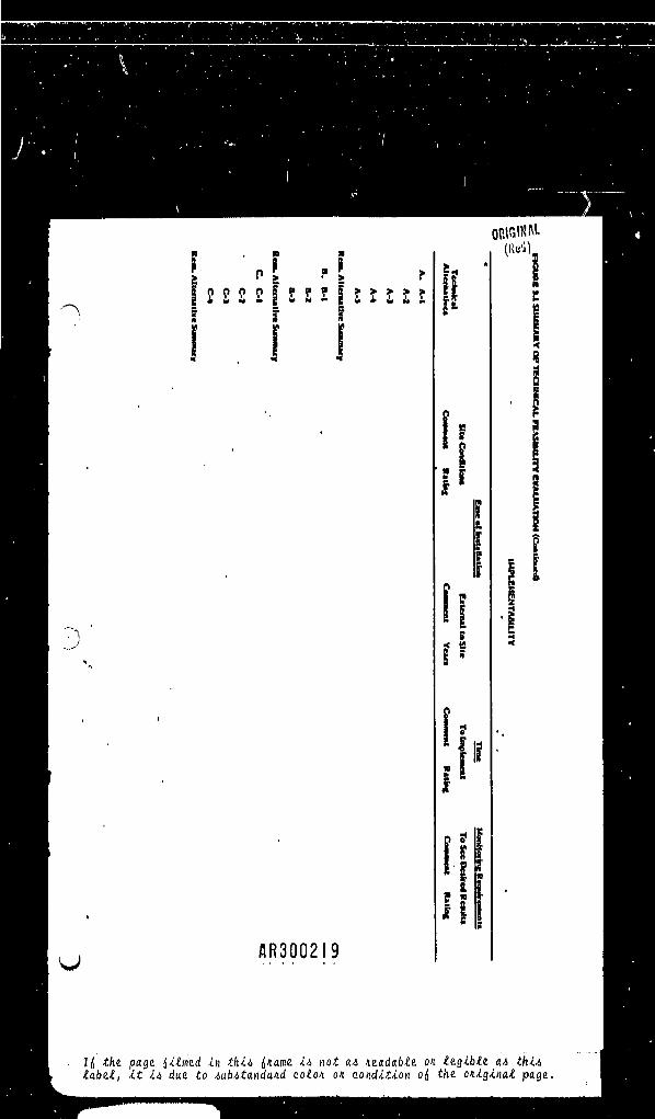
3.5 SUMMARY OF TECHNICAL FEASIBILITY.
Figure 3-1 will aitlit the uier in evaluating the rimidial alternative!baaed on performance, reliability, implementability and lafety conilderitioni.The varlout tachnologiea which comprii* each alternative will be evaluatedIndividually; after which an overall rating will be determined for thatalternative, The uier ihould men ilte conditiona that would affect theconitructabillty of any technology and determine deilgn and/or iltlnz. criteria
3-6 • AR3002I7
Id the page filmed in thiA {name iA not aA ntadable on legible aA thiA(abet, it iA due to AubAtandand colon on condition of, the oniginal page.

! 'P! r!I 2 2 2 £ | S S 2 f t I I I I\ ' I £1 ! i
/IR3002I8
|H '
ORlGM(Red)
1 -
jl»1
i'!
Prniou
r^mmifl Ratlnf
e|O
|• s :
G
I(j the page darned in thiA {name iA not aA neadable on legible aA thiAlabel, it iA due to AubAtandand colon on condition o{ the oniginal page.
)
ORIGWM-f i g »
p» • 1"£ P > • > fI 2 2 2 2 I S S I I 2 It I If 1 f
I I I
•
•
AR3002I9
Is!i
h
sf"
IffI1I I II •*l|
«'j)
c
<Ǥ
I
|!•
•
Id the page {ilmea. in thiA {name iA not aA neadable on legible aA thiAlabel, it iA due to AubAtandand colon on condition o{ the oniginal page.

' ' P !1 ?. pj fI 2 £ 2 £ i z E ! 1 .????.?'
j; f •
1
AR300220
*- tf:«i'II 'i
j1
1
hi,S r ,
1i
5 1
\ 1I 1? |
(HAL |•;d) g
|5?Q
fi
1
Id ihe page dimmed in thiA {name iA not aA neadabte on legible aA thiAlabel, it iA due to AubAtandand colon on condition o{ the oniginal page.

ORIGINAL(Red)
to achieve a favorable outlook for conatruction. Th* uaer ihould rank eachalternative bated on It* component technologic*. However, the uier ihouldexplicitly determine the** Individual component* of th* overall coet-
. effectiveneit analyaii. Hiaaurei that aggregate many factora cannot beeffectively und in dletinguiihlng between alternative! having aimllar coat-effectiveneaa ratioa. See Chapter 8 for further diacuaaion of thia concipt,
On Figure 3-1 alternative* are Hated In the left column. Eachalternative li described In termi of It* component technologiei. Theie areindicated by A-l, A-2, and ao on, of alternative "A" In the Table, Forexample, alternative "A" may conalat of lit* capping, divirilon ditch**, a•lurry wall, groundwatir pumping, and treatment of th* effluent. The u**r maychooie to rank the alternativea and tachnologlei In order of their relativedeairablllty with reipect to each criterion, or to rate each alternative andtechnology with reipect to the abiolute degree to which the alternative ortechnology effectively fulfllla eich criterion. If the relicive evaluation
"»method li choien the hlgheit number It generally the number of alternative!under coniideratlon. If the abaolute evaluation method ia choien the•numerlcel valuei are generally rangei luch as 1 to 10, 1 to 5 or -1, 0, +1,with the loweit number representing a "baae line" alternative. Whichever lichoien, the uier ihould provide a conaiitent numerical nnklng with thehigheit number indiciting the uoic diiirable alternative or technology undereach criterion.
The only exception to the above acorlng la the criterion for tine, Thenumerical value for tine ahould be the number of montha or yeara relevant to
. each technology or alternative. The overall time ihould be the turn of thetime required for implementation and to achieve beneficial reiulti. Note thatthe time to eee btn*fielal reiulti ihould not include implementation time.
< In eddltion to th* numerical deicrlptio'ni of each alternitive there itallowance for cooaanta, The connenti under each lub-headlng ihould Includeany outitandlng faaturca which render the technology particularly deilrable,or any llmltatloni which may hinder Iti uae for remedial action at the.iite.
AR30022I3-8
Id the page f,ilmed in thiA {name iA not aA neadable on legible aA thiAlabel, if. iA due to AubAtandand colon on condition o{ the oniginat page.