Embed Size (px)
Citation preview
KS-KD-Actuated-Ball-Valves.pub | tel: (650) 856-8833 www.StcValve.com | Version 1.0, 3/30/2018
1
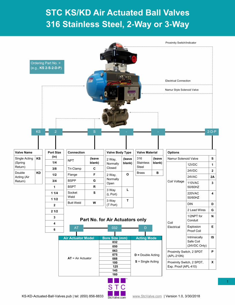
STC KS/KD Air Actuated Ball Valves
316 Stainless Steel, 2-Way or 3-Way
Ordering Part No. =
(e.g., KS 2-S-2-D-P)
Connection
NPT (leave
blank)
Tri-Clamp C
Flange F
BSPP G
BSPT R
Socket
Weld
S
Butt Weld W
Valve Body Type
2 Way,
Normally
Closed
(leave
blank)
2 Way,
Normally
Open
O
3 Way
(L Port)
L
3 Way
(T Port)
T
Valve Material
316
Stainless
Steel
(leave
blank)
Brass B
Port Size
(in)
1/4
3/8
1/2
3/4
1
1 1/4
1 1/2
2
2 1/2
3
4
6
-
Valve Name
Single Acting
(Spring
Return)
KS
Double
Acting (Air
Return)
KD
Options
Namur Solenoid Valve S
Coil Voltage
12VDC 1
24VDC 2
24VAC 2A
110VAC
50/60HZ
3
220VAC
50/60HZ
4
DIN D
Coil
Electrical
2 Lead Wires G
1/2NPT for
Conduit
N
Explosion
Proof Coil
E
Intrinsically
Safe Coil
(24VDC Only)
IS
Proximity Switch, 2 SPDT
(APL-210N)
P
Proximity Switch, 2 SPDT,
Exp. Proof (APL-410)
X
KS 2 S - 2-D-P
Proximity Switch/Indicator
Electrical Connection
Namur Style Solenoid Valve
Air Actuator Model Bore Size (mm) Acting Mode
AT = Air Actuator
032
D = Double Acting
S = Single Acting
050
063
075
088
100
125
145
160
Part No. for Air Actuators only
D AT 032
KS-KD-Actuated-Ball-Valves.pub | tel: (650) 856-8833 www.StcValve.com | Version 1.0, 3/30/2018
2
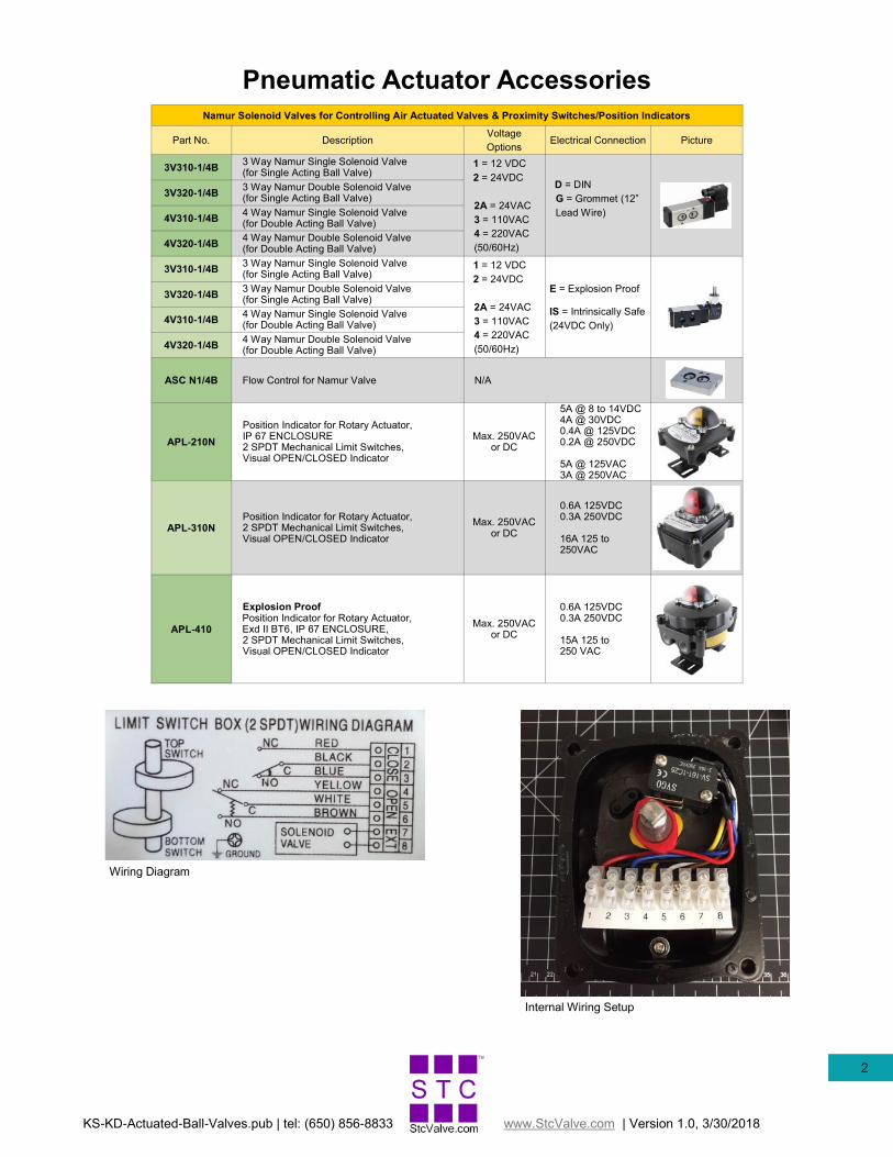
Pneumatic Actuator Accessories Namur Solenoid Valves for Controlling Air Actuated Valves & Proximity Switches/Position Indicators
Part No. Description Voltage
Options Electrical Connection Picture
3V310-1/4B 3 Way Namur Single Solenoid Valve (for Single Acting Ball Valve)
1 = 12 VDC
2 = 24VDC
2A = 24VAC
3 = 110VAC
4 = 220VAC
(50/60Hz)
D = DIN
G = Grommet (12”
Lead Wire)
3V320-1/4B 3 Way Namur Double Solenoid Valve (for Single Acting Ball Valve)
4V310-1/4B 4 Way Namur Single Solenoid Valve (for Double Acting Ball Valve)
4V320-1/4B 4 Way Namur Double Solenoid Valve (for Double Acting Ball Valve)
3V310-1/4B 3 Way Namur Single Solenoid Valve (for Single Acting Ball Valve)
1 = 12 VDC
2 = 24VDC
2A = 24VAC
3 = 110VAC
4 = 220VAC
(50/60Hz)
E = Explosion Proof
IS = Intrinsically Safe
(24VDC Only)
3V320-1/4B 3 Way Namur Double Solenoid Valve (for Single Acting Ball Valve)
4V310-1/4B 4 Way Namur Single Solenoid Valve (for Double Acting Ball Valve)
4V320-1/4B 4 Way Namur Double Solenoid Valve (for Double Acting Ball Valve)
ASC N1/4B Flow Control for Namur Valve N/A
APL-210N
Position Indicator for Rotary Actuator, IP 67 ENCLOSURE 2 SPDT Mechanical Limit Switches, Visual OPEN/CLOSED Indicator
Max. 250VAC or DC
5A @ 8 to 14VDC 4A @ 30VDC 0.4A @ 125VDC 0.2A @ 250VDC 5A @ 125VAC 3A @ 250VAC
APL-310N Position Indicator for Rotary Actuator, 2 SPDT Mechanical Limit Switches, Visual OPEN/CLOSED Indicator
Max. 250VAC or DC
0.6A 125VDC 0.3A 250VDC 16A 125 to 250VAC
APL-410
Explosion Proof Position Indicator for Rotary Actuator, Exd II BT6, IP 67 ENCLOSURE, 2 SPDT Mechanical Limit Switches, Visual OPEN/CLOSED Indicator
Max. 250VAC or DC
0.6A 125VDC 0.3A 250VDC 15A 125 to 250 VAC
Internal Wiring Setup
Wiring Diagram
KS-KD-Actuated-Ball-Valves.pub | tel: (650) 856-8833 www.StcValve.com | Version 1.0, 3/30/2018
3
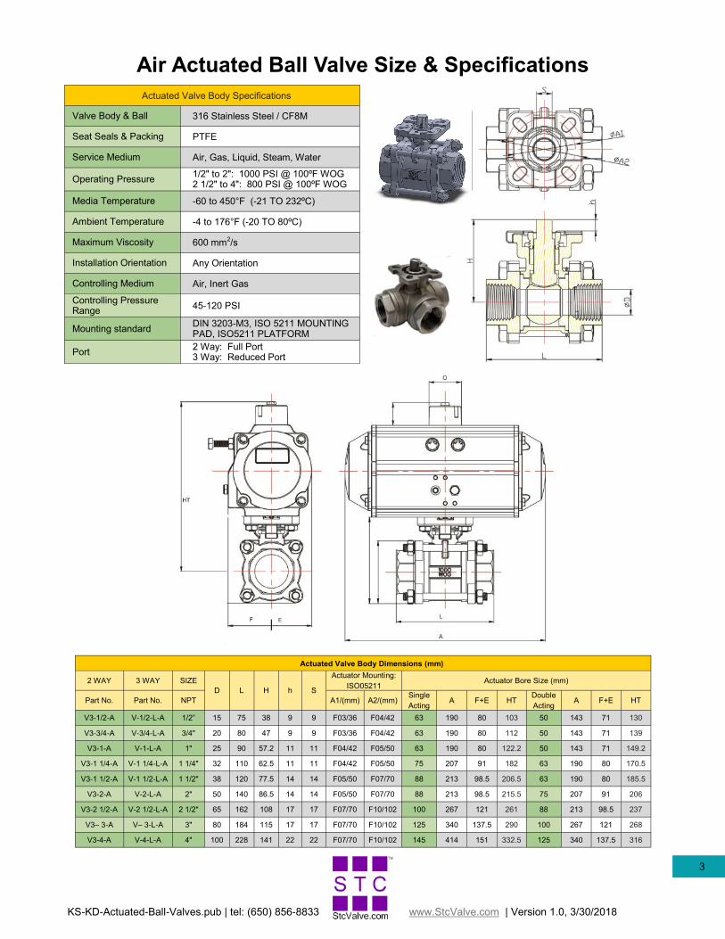
Air Actuated Ball Valve Size & Specifications
Actuated Valve Body Specifications
Valve Body & Ball 316 Stainless Steel / CF8M
Seat Seals & Packing PTFE
Service Medium Air, Gas, Liquid, Steam, Water
Operating Pressure 1/2" to 2": 1000 PSI @ 100ºF WOG 2 1/2" to 4": 800 PSI @ 100ºF WOG
Media Temperature -60 to 450°F (-21 TO 232ºC)
Ambient Temperature -4 to 176°F (-20 TO 80ºC)
Maximum Viscosity 600 mm2/s
Installation Orientation Any Orientation
Controlling Medium Air, Inert Gas
Controlling Pressure Range
45-120 PSI
Mounting standard DIN 3203-M3, ISO 5211 MOUNTING PAD, ISO5211 PLATFORM
Port 2 Way: Full Port 3 Way: Reduced Port
Actuated Valve Body Dimensions (mm)
2 WAY 3 WAY SIZE
D L H h
Actuator Mounting:
ISO05211 Actuator Bore Size (mm)
S
Part No. Part No. NPT A1/(mm) A2/(mm) Single
Acting A F+E HT
Double
Acting A F+E HT
V3-1/2-A V-1/2-L-A 1/2” 15 75 38 9 9 F03/36 F04/42 63 190 80 103 50 143 71 130
V3-3/4-A V-3/4-L-A 3/4" 20 80 47 9 9 F03/36 F04/42 63 190 80 112 50 143 71 139
V3-1-A V-1-L-A 1" 25 90 57.2 11 11 F04/42 F05/50 63 190 80 122.2 50 143 71 149.2
V3-1 1/4-A V-1 1/4-L-A 1 1/4" 32 110 62.5 11 11 F04/42 F05/50 75 207 91 182 63 190 80 170.5
V3-1 1/2-A V-1 1/2-L-A 1 1/2" 38 120 77.5 14 14 F05/50 F07/70 88 213 98.5 206.5 63 190 80 185.5
V3-2-A V-2-L-A 2" 50 140 86.5 14 14 F05/50 F07/70 88 213 98.5 215.5 75 207 91 206
V3-2 1/2-A V-2 1/2-L-A 2 1/2" 65 162 108 17 17 F07/70 F10/102 100 267 121 261 88 213 98.5 237
V3– 3-A V– 3-L-A 3" 80 184 115 17 17 F07/70 F10/102 125 340 137.5 290 100 267 121 268
V3-4-A V-4-L-A 4" 100 228 141 22 22 F07/70 F10/102 145 414 151 332.5 125 340 137.5 316
KS-KD-Actuated-Ball-Valves.pub | tel: (650) 856-8833 www.StcValve.com | Version 1.0, 3/30/2018
4
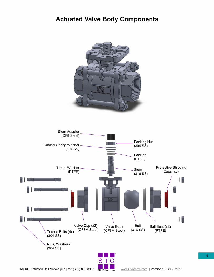
Stem (316 SS)
Nuts, Washers (304 SS)
Valve Cap (x2) (CF8M Steel)
Actuated Valve Body Components
Torque Bolts (4x) (304 SS)
Valve Body (CF8M Steel)
Ball (316 SS)
Ball Seat (x2) (PTFE)
Thrust Washer (PTFE)
Packing (PTFE)
Conical Spring Washer (304 SS)
Packing Nut (304 SS)
Stem Adapter (CF8 Steel)
Protective Shipping Caps (x2)
KS-KD-Actuated-Ball-Valves.pub | tel: (650) 856-8833 www.StcValve.com | Version 1.0, 3/30/2018
5
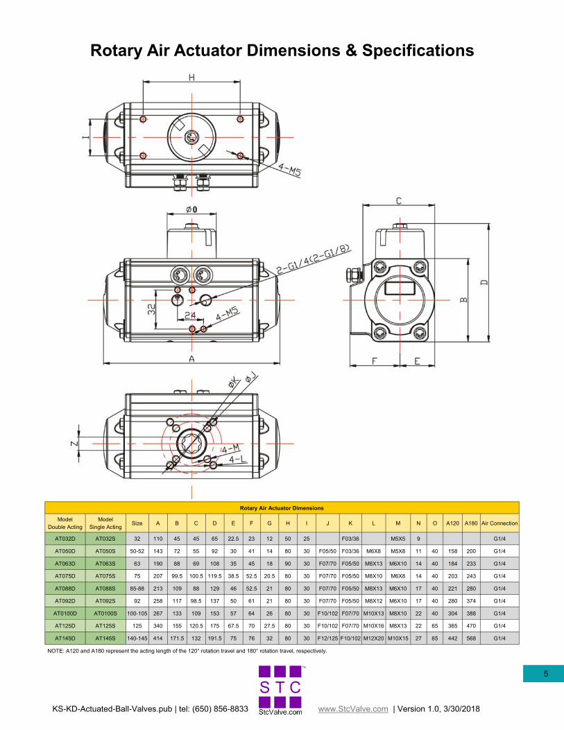
Rotary Air Actuator Dimensions & Specifications
Rotary Air Actuator Dimensions
Model
Double Acting
Model
Single Acting Size A B C D E F G H I J K L M N O A120 A180 Air Connection
AT032D AT032S 32 110 45 45 65 22.5 23 12 50 25 F03/36 M5X5 9 G1/4
AT050D AT050S 50-52 143 72 55 92 30 41 14 80 30 F05/50 F03/36 M6X8 M5X8 11 40 158 200 G1/4
AT063D AT063S 63 190 88 69 108 35 45 18 90 30 F07/70 F05/50 M8X13 M6X10 14 40 184 233 G1/4
AT075D AT075S 75 207 99.5 100.5 119.5 38.5 52.5 20.5 80 30 F07/70 F05/50 M8X10 M6X8 14 40 203 243 G1/4
AT088D AT088S 85-88 213 109 88 129 46 52.5 21 80 30 F07/70 F05/50 M8X13 M6X10 17 40 221 280 G1/4
AT092D AT092S 92 258 117 98.5 137 50 61 21 80 30 F07/70 F05/50 M8X12 M6X10 17 40 280 374 G1/4
AT0100D AT0100S 100-105 267 133 109 153 57 64 26 80 30 F10/102 F07/70 M10X13 M8X10 22 40 304 388 G1/4
AT125D AT125S 125 340 155 120.5 175 67.5 70 27.5 80 30 F10/102 F07/70 M10X16 M8X13 22 65 365 470 G1/4
AT145D AT145S 140-145 414 171.5 132 191.5 75 76 32 80 30 F12/125 F10/102 M12X20 M10X15 27 65 442 568 G1/4
NOTE: A120 and A180 represent the acting length of the 120° rotation travel and 180° rotation travel, respectively.
KS-KD-Actuated-Ball-Valves.pub | tel: (650) 856-8833 www.StcValve.com | Version 1.0, 3/30/2018
6
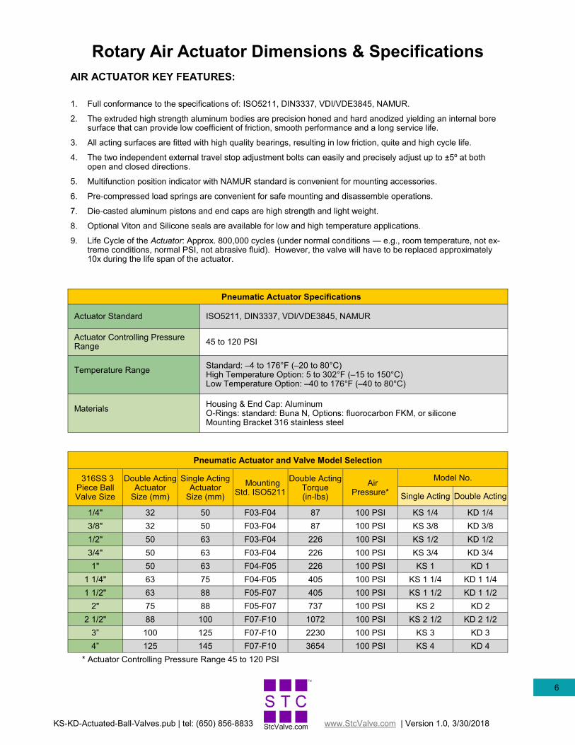
Rotary Air Actuator Dimensions & Specifications
Pneumatic Actuator Specifications
Actuator Standard ISO5211, DIN3337, VDI/VDE3845, NAMUR
Actuator Controlling Pressure Range
45 to 120 PSI
Temperature Range
Standard: –4 to 176°F (–20 to 80°C) High Temperature Option: 5 to 302°F (–15 to 150°C) Low Temperature Option: –40 to 176°F (–40 to 80°C)
Materials
Housing & End Cap: Aluminum O-Rings: standard: Buna N, Options: fluorocarbon FKM, or silicone Mounting Bracket 316 stainless steel
Pneumatic Actuator and Valve Model Selection
316SS 3 Piece Ball Valve Size
Double Acting Actuator
Size (mm)
Single Acting Actuator
Size (mm)
Mounting Std. ISO5211
Double Acting Torque (in-lbs)
Model No. Air
Pressure* Single Acting Double Acting
1/4" 32 50 F03-F04 87 100 PSI KS 1/4 KD 1/4
3/8" 32 50 F03-F04 87 100 PSI KS 3/8 KD 3/8
1/2" 50 63 F03-F04 226 100 PSI KS 1/2 KD 1/2
3/4" 50 63 F03-F04 226 100 PSI KS 3/4 KD 3/4
1" 50 63 F04-F05 226 100 PSI KS 1 KD 1
1 1/4" 63 75 F04-F05 405 100 PSI KS 1 1/4 KD 1 1/4
1 1/2" 63 88 F05-F07 405 100 PSI KS 1 1/2 KD 1 1/2
2" 75 88 F05-F07 737 100 PSI KS 2 KD 2
2 1/2" 88 100 F07-F10 1072 100 PSI KS 2 1/2 KD 2 1/2
3” 100 125 F07-F10 2230 100 PSI KS 3 KD 3
4” 125 145 F07-F10 3654 100 PSI KS 4 KD 4
* Actuator Controlling Pressure Range 45 to 120 PSI
AIR ACTUATOR KEY FEATURES:
1. Full conformance to the specifications of: ISO5211, DIN3337, VDI/VDE3845, NAMUR.
2. The extruded high strength aluminum bodies are precision honed and hard anodized yielding an internal bore surface that can provide low coefficient of friction, smooth performance and a long service life.
3. All acting surfaces are fitted with high quality bearings, resulting in low friction, quite and high cycle life.
4. The two independent external travel stop adjustment bolts can easily and precisely adjust up to ±5º at both open and closed directions.
5. Multifunction position indicator with NAMUR standard is convenient for mounting accessories.
6. Pre-compressed load springs are convenient for safe mounting and disassemble operations.
7. Die-casted aluminum pistons and end caps are high strength and light weight.
8. Optional Viton and Silicone seals are available for low and high temperature applications.
9. Life Cycle of the Actuator: Approx. 800,000 cycles (under normal conditions — e.g., room temperature, not ex-treme conditions, normal PSI, not abrasive fluid). However, the valve will have to be replaced approximately 10x during the life span of the actuator.
KS-KD-Actuated-Ball-Valves.pub | tel: (650) 856-8833 www.StcValve.com | Version 1.0, 3/30/2018
7
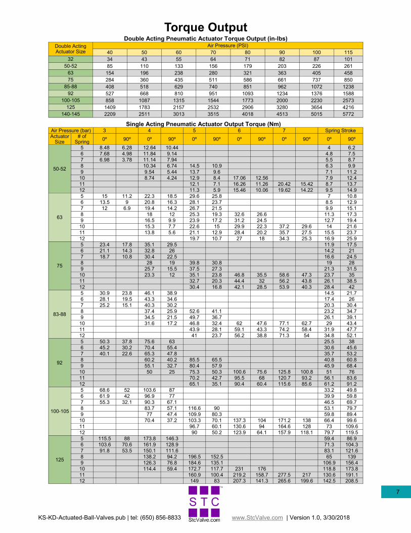
Torque Output
Single Acting Pneumatic Actuator Output Torque (Nm) Air Pressure (bar) 3 4 5 6 7 Spring Stroke Actuator
Size # of
Spring 0º 90º 0º 90º 0º 90º 0º 90º 0º 90º 0º 90º
50-52
5 8.48 6.28 12.64 10.44 4 6.2
6 7.68 4.98 11.84 9.14 4.8 7.5
7 6.98 3.78 11.14 7.94 5.5 8.7
8 10.34 6.74 14.5 10.9 6.3 9.9
9 9.54 5.44 13.7 9.6 7.1 11.2
10 8.74 4.24 12.9 8.4 17.06 12.56 7.9 12.4
11 12.1 7.1 16.26 11.26 20.42 15.42 8.7 13.7
12 11.3 5.9 15.46 10.06 19.62 14.22 9.5 14.9
63
5 15 11.2 22.3 18.5 29.6 25.8 7 10.8
6 13.5 9 20.8 16.3 28.1 23.7 8.5 12.9
7 12 6.9 19.4 14.2 26.7 21.5 9.9 15.1
8 18 12 25.3 19.3 32.6 26.6 11.3 17.3
9 16.5 9.9 23.9 17.2 31.2 24.5 12.7 19.4
10 15.3 7.7 22.6 15 29.9 22.3 37.2 29.6 14 21.6
11 13.8 5.6 21.1 12.9 28.4 20.2 35.7 27.5 15.5 23.7
12 19.7 10.7 27 18 34.3 25.3 16.9 25.9
75
5 23.4 17.8 35.1 29.5 11.9 17.5
6 21.1 14.3 32.8 26 14.2 21
7 18.7 10.8 30.4 22.5 16.6 24.5
8 28 19 39.8 30.8 19 28
9 25.7 15.5 37.5 27.3 21.3 31.5
10 23.3 12 35.1 23.8 46.8 35.5 58.6 47.3 23.7 35
11 32.7 20.3 44.4 32 56.2 43.8 26.1 38.5
12 30.4 16.8 42.1 28.5 53.9 40.3 28.4 42
83-88
5 30.9 23.8 46.1 38.9 14.5 21.7
6 28.1 19.5 43.3 34.6 17.4 26
7 25.2 15.1 40.3 30.2 20.3 30.4
8 37.4 25.9 52.6 41.1 23.2 34.7
9 34.5 21.5 49.7 36.7 26.1 39.1
10 31.6 17.2 46.8 32.4 62 47.6 77.1 62.7 29 43.4
11 43.9 28.1 59.1 43.3 74.2 58.4 31.9 47.7
12 41 23.7 56.2 38.8 71.3 54 34.8 52.1
92
5 50.3 37.8 75.6 63 25.5 38
6 45.2 30.2 70.4 55.4 30.6 45.6
7 40.1 22.6 65.3 47.8 35.7 53.2
8 60.2 40.2 85.5 65.5 40.8 60.8
9 55.1 32.7 80.4 57.9 45.9 68.4
10 50 25 75.3 50.3 100.6 75.6 125.8 100.8 51 76
11 70.2 42.7 95.5 68 120.7 93.2 56.1 83.6
12 65.1 35.1 90.4 60.4 115.6 85.6 61.2 91.2
100-105
5 68.6 52 103.6 87 33.2 49.8
6 61.9 42 96.9 77 39.9 59.8
7 55.3 32.1 90.3 67.1 46.5 69.7
8 83.7 57.1 116.6 90 53.1 79.7
9 77 47.4 109.9 80.3 59.8 89.4
10 70.4 37.2 103.3 70.1 137.3 104 171.2 138 66.4 99.6
11 96.7 60.1 130.6 94 164.6 128 73 109.6
12 90 50.2 123.9 64.1 157.9 118.1 79.7 119.5
125
5 115.5 88 173.8 146.3 59.4 86.9
6 103.6 70.6 161.9 128.9 71.3 104.3
7 91.8 53.5 150.1 111.6 83.1 121.6
8 138.2 94.2 196.5 152.5 65 139
9 126.3 76.8 184.6 135.1 106.9 156.4
10 114.4 59.4 172.7 117.7 231 176 118.8 173.8
11 160.9 100.4 219.2 158.7 277.5 217 130.6 191.1
12 149 83 207.3 141.3 265.6 199.6 142.5 208.5
Double Acting Pneumatic Actuator Torque Output (in-lbs)
Double Acting Actuator Size
Air Pressure (PSI)
40 50 60 70 80 90 100 115
32 34 43 55 64 71 82 87 101
50-52 85 110 133 156 179 203 226 261
63 154 196 238 280 321 363 405 458
75 284 360 435 511 586 661 737 850
85-88 408 518 629 740 851 962 1072 1238
92 527 668 810 951 1093 1234 1376 1588
100-105 858 1087 1315 1544 1773 2000 2230 2573
125 1409 1783 2157 2532 2906 3280 3654 4216
140-145 2209 2511 3013 3515 4018 4513 5015 5772
KS-KD-Actuated-Ball-Valves.pub | tel: (650) 856-8833 www.StcValve.com | Version 1.0, 3/30/2018
8
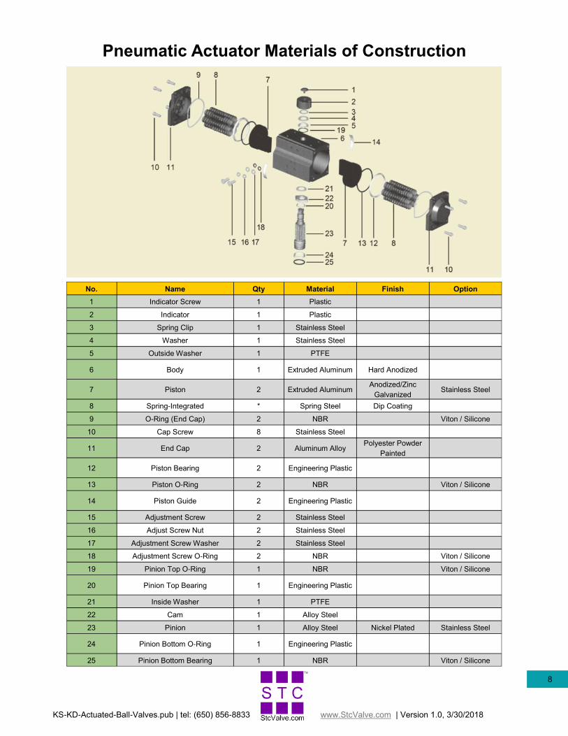
Pneumatic Actuator Materials of Construction
No. Name Material Finish Option Qty
1 Indicator Screw Plastic 1
2 Indicator Plastic 1
3 Spring Clip Stainless Steel 1
4 Washer Stainless Steel 1
5 Outside Washer PTFE 1
6 Body Extruded Aluminum Hard Anodized 1
7 Piston Extruded Aluminum Anodized/Zinc
Galvanized Stainless Steel 2
8 Spring-Integrated Spring Steel Dip Coating *
9 O-Ring (End Cap) NBR Viton / Silicone 2
10 Cap Screw Stainless Steel 8
11 End Cap Aluminum Alloy Polyester Powder
Painted 2
12 Piston Bearing Engineering Plastic 2
13 Piston O-Ring NBR Viton / Silicone 2
14 Piston Guide Engineering Plastic 2
15 Adjustment Screw Stainless Steel 2
16 Adjust Screw Nut Stainless Steel 2
17 Adjustment Screw Washer Stainless Steel 2
18 Adjustment Screw O-Ring NBR Viton / Silicone 2
19 Pinion Top O-Ring NBR Viton / Silicone 1
20 Pinion Top Bearing Engineering Plastic 1
21 Inside Washer PTFE 1
22 Cam Alloy Steel 1
23 Pinion Alloy Steel Nickel Plated Stainless Steel 1
24 Pinion Bottom O-Ring Engineering Plastic 1
25 Pinion Bottom Bearing NBR Viton / Silicone 1
KS-KD-Actuated-Ball-Valves.pub | tel: (650) 856-8833 www.StcValve.com | Version 1.0, 3/30/2018
9
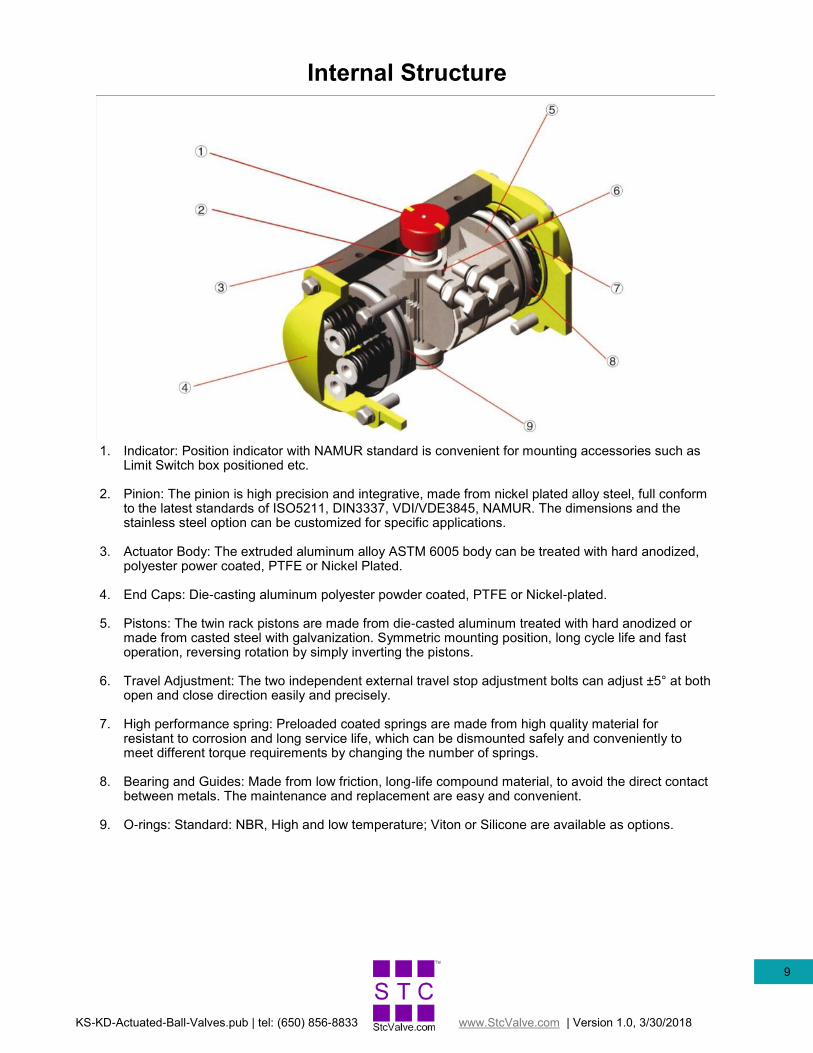
Internal Structure
1. Indicator: Position indicator with NAMUR standard is convenient for mounting accessories such as Limit Switch box positioned etc.
2. Pinion: The pinion is high precision and integrative, made from nickel plated alloy steel, full conform to the latest standards of ISO5211, DIN3337, VDI/VDE3845, NAMUR. The dimensions and the stainless steel option can be customized for specific applications.
3. Actuator Body: The extruded aluminum alloy ASTM 6005 body can be treated with hard anodized, polyester power coated, PTFE or Nickel Plated.
4. End Caps: Die-casting aluminum polyester powder coated, PTFE or Nickel-plated.
5. Pistons: The twin rack pistons are made from die-casted aluminum treated with hard anodized or made from casted steel with galvanization. Symmetric mounting position, long cycle life and fast operation, reversing rotation by simply inverting the pistons.
6. Travel Adjustment: The two independent external travel stop adjustment bolts can adjust ±5° at both open and close direction easily and precisely.
7. High performance spring: Preloaded coated springs are made from high quality material for resistant to corrosion and long service life, which can be dismounted safely and conveniently to meet different torque requirements by changing the number of springs.
8. Bearing and Guides: Made from low friction, long-life compound material, to avoid the direct contact between metals. The maintenance and replacement are easy and convenient.
9. O-rings: Standard: NBR, High and low temperature; Viton or Silicone are available as options.
KS-KD-Actuated-Ball-Valves.pub | tel: (650) 856-8833 www.StcValve.com | Version 1.0, 3/30/2018
10
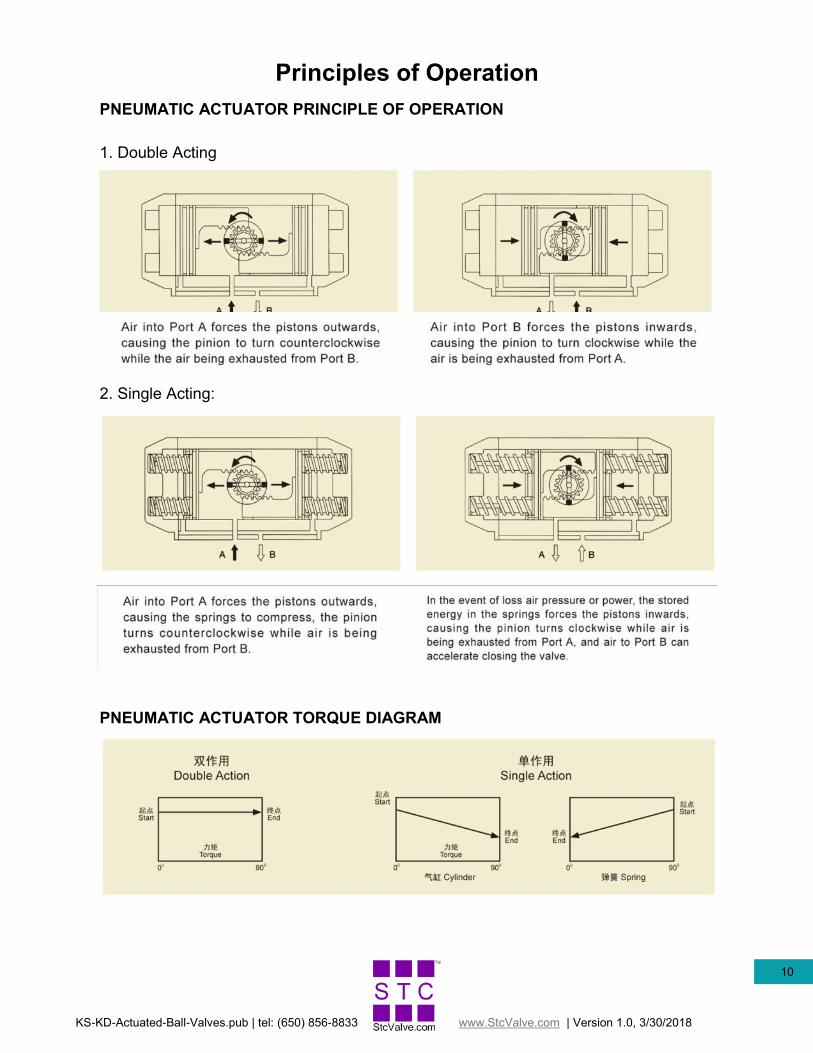
Principles of Operation
PNEUMATIC ACTUATOR PRINCIPLE OF OPERATION
1. Double Acting
2. Single Acting:
PNEUMATIC ACTUATOR TORQUE DIAGRAM

KS-KD-Actuated-Ball-Valves.pub | tel: (650) 856-8833 www.StcValve.com | Version 1.0, 3/30/2018
11
Namur Solenoid Valve Installation
EA/EB = Exhaust P=SUPPLY AIR
1. Lay out the KS/KD series air actuated ball valve with the control ports on the air actuator facing upward as in FIG. 1 below.
2. Make sure the O-ring(s) is properly seated on port in the Namur solenoid valve as in FIG. 2 below.
3. Put the Namur solenoid valve on top of the KS/KD actuator with the solenoid coil on the left side as shown in FIG. 3.
4. Fasten the Namur solenoid valve onto the KS/KD actuator with the two socket head screws as shown in FIG. 4 and tighten to 1.5 to 2 lb-ft.
torque.
5. Connect the supply air to port P as shown in FIG. 4, connect a muffler to the exhaust port is recommended.
6. Follow the electrical connection procedure to connect the coil on the Namur solenoid valve.
FIG. 1 FIG. 2
FIG. 3 FIG. 4
Valve Position Indicator
KS/KD Valve Actuator
3 Way Namur Solenoid Valve for
KS Single Acting Actuator
O-Ring Solenoid Coil
Ball Valve
Actuator Control Port
Namur Solenoid Valve
Mounting Holes
Socket Head Screw
Manual Over-ride
FIG. 2A
4 Way Namur Solenoid Valve for
KD Double Acting Actuator
KS-KD-Actuated-Ball-Valves.pub | tel: (650) 856-8833 www.StcValve.com | Version 1.0, 3/30/2018
12
Electrical Connection Procedure
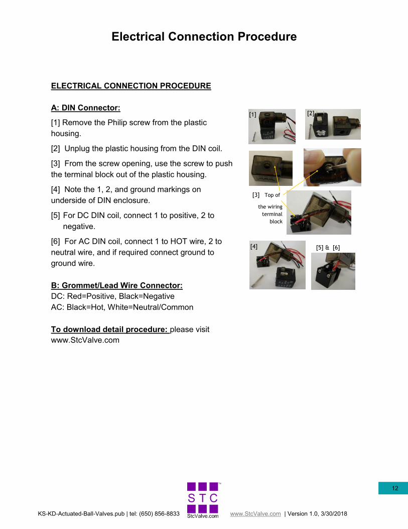
ELECTRICAL CONNECTION PROCEDURE
A: DIN Connector:
[1] Remove the Philip screw from the plastic
housing.
[2] Unplug the plastic housing from the DIN coil.
[3] From the screw opening, use the screw to push
the terminal block out of the plastic housing.
[4] Note the 1, 2, and ground markings on
underside of DIN enclosure.
[5] For DC DIN coil, connect 1 to positive, 2 to
negative.
[6] For AC DIN coil, connect 1 to HOT wire, 2 to
neutral wire, and if required connect ground to
ground wire.
B: Grommet/Lead Wire Connector:
DC: Red=Positive, Black=Negative
AC: Black=Hot, White=Neutral/Common
To download detail procedure: please visit
www.StcValve.com
[1] [2]
[3] Top of
the wiring
terminal
block
[4] [5] & [6]

KS-KD-Actuated-Ball-Valves.pub | tel: (650) 856-8833 www.StcValve.com | Version 1.0, 3/30/2018
13
Installation Guide
Note: This valve is designed to be controlled by air flow only. Any kind of COMPATIBLE fluid may flow through the
valve body.
Adjusting the valve’s default position:
1. Remove the four bolts underneath the actuator.
2. Separate the actuator from the valve.
3. Rotate the valve to the desired default position.
4. Place the actuator back on the valve and screw everything back into place.
Connection to fluid supply:
1. Connect the main fluid ball valve to the primary source and primary outlet.
2. Connect the control supply to the actuator. If the actuator is double acting, air supplied to the right port will open the
valve, and the air supplied to the left port will close the valve.
Connection to Position Indicator:
1. Remove the bolt and cap covering the slot at the top of the actuator.
2. Set the indicator to the default/current position and place it so that the key fits in the slot.
3. Screw the bracket holding the indicator in place.
Adjustment:
The angle of the actuator can be adjusted if the actuator becomes misaligned during operation. To realign the actuator, adjust the
two screws near the top of the actuator, above the air supply ports. Ensure that the screws are tightened down after adjustment.
Warning: When tightening any connections to the valve, do not use the actuator as leverage. Doing so may damage
the joint between the actuator and the valve.
Figure 1: [Left] Model KS-1 and [Right] Mode KD-1. Main valve body is
under the actuator.
Figure 2: KD-1 1/2 with solenoid control-
ler and indicator attached.
Figure 3: Valve without actuator. The key may be rotated to either normally
open or closed position.

KS-KD-Actuated-Ball-Valves.pub | tel: (650) 856-8833 www.StcValve.com | Version 1.0, 3/30/2018
14
Maintenance
Note: This valve is designed to last for an extended time period. However, common maintenance is necessary. If a
leak begins to develop on the valve body, please consult these common maintenance procedures for a solution.
Tightening the seal between the valve and the actuator:
This valve does not have a dynamic seal (i.e., no spring), therefore as the valve ages, the seal between the valve and the actuator
body must be periodically tightened manually.
1. Remove the four bolts underneath the actuator.
2. Separate the actuator from the valve.
3. Tighten the nut on the top of the valve body. See figure one for location.
4. Place the actuator back on the valve and screw everything back into place.
Tightening the seals between the valve and the inlet/outlet ports:
Leaks developing in the inlet/outlet ports are often caused by inconsistent tightening of the torque bolts on the valve body. If this
occurs, make sure to use a consistent method of tightening these bolts to ensure consistent torque.
1. Remove the torque bolts and check for any debris or damage to the gaskets.
2. Use a torque wrench or other consistent method of tightening the torque bolts to reconnect the inlet and outlet ports.
Warning: When tightening any connections to the valve, do not use the actuator as leverage. Doing so may damage
the joint between the actuator and the valve.
Reference Figures:
Figure 1: Exploded view of valve body with
tightening nut indicated.
Figure 3: Model KS-1 with torque bolts indicated.
Tightening Nut
Figure 2: Valve Body without actuator with
tightening nut indicated.
Torque Bolts (4x)

KS-KD-Actuated-Ball-Valves.pub | tel: (650) 856-8833 www.StcValve.com | Version 1.0, 3/30/2018
15
Reconfiguration
4 SCREWS
BALL VALVE STEM
BALL VALVE
ACTUATOR
To re-configure a normally closed valve to a normally open valve:
1. Turn off the air supply to the air actuator.
2. Remove the 4 SCREWS on the bottom of the ACTUATOR.
3. Remove the BALL VALVE from the ACTUATOR.
4. Turn the BALL VALVE STEM on the ball valve 90 degree such at the valve is fully open (visually inspect the ball to make
sure it is open).
5. Put the BALL VALVE back into the ACTUATOR and re-install the 4 SCREWS.
www.StcValve.com
16 Sizto Tech Corporation
892 Commercial Street
Palo Alto, CA 94303 USA
Tel: (650) 856-8833 | Fax: (650) 856-8811
Email: [email protected] | www.StcValve.com
Information contained herein may be changed without prior notification.
By purchasing from SIZTO TECH CORPORATION (STC), you agree to these TERMS AND CONDITIONS. No other terms shall apply except as agreed in writing & signed by STC. We reserve the right to correct typographic errors and reject orders. SHIPMENTS: All shipments are F.O.B. 892 Commercial Street, Palo Alto, CA 94303, USA. Most orders are shipped via UPS Standard Ground unless instructions accompany order. Outside the UPS zones, shipment will be made Best Way. The responsibility for goods delay, lost or damaged in transit rests with the carrier and purchaser. Purchaser may purchase shipping insurance to cover lost or damaged products caused by shipping. RETURN OF MERCHANDISE: No merchandise is accepted for return 30 days after delivery date. No credit allowed on merchandise shipped as ordered and returned without obtaining an authorization number IN ADVANCE. A 20% restocking charge applies to all returns, and transpor-tation charges must be fully prepaid. We will pay ground transportation charges on re-sent or returned merchandise due to STC's error. Shortages & Mis-Shipments: Any shortages or mis-shipments must be reported within 15 days. CANCELLATION POLICY: Blanket orders can be canceled 90 days before scheduled ship date. There will be a 10% charge if a blanket order is canceled within 90 days of scheduled ship date, and a 20% charge if canceled within 60 days. Regular orders for non-custom parts can be canceled any time before the order is shipped. For custom parts, a 30% down payment is required either at the time of order or 90 days prior to scheduled ship date, whichever comes later. . Remittances should be sent to: Sizto Tech Corporation, 892 Commercial Street, Palo Alto, CA 94303, USA Credit Card Payments: Visa, MasterCard, Discover, or American Express accepted International Customers: Advance Payment Required via Bank Wire, Cashier's Check or Approved Credit Card. Credit Application: To establish a net 30 day account, please mail or fax three trade references with complete mailing address-es and account numbers, or request an STC Credit Application. LIMITED WARRANTY – IMPORTANT NOTICE TO PURCHASER: Sizto Tech Corporation (STC) only warrants this product to be free from defects in materials and workmanship at the time of shipment. This limited warranty expires one year after delivery to the end-user. STC’s entire obligation to the Purchaser for breach of this limited warranty shall be limited to replacement of the defective product or refund of the original purchase price of this product, at STC’s option. Purchaser has thirty (30) days to return the goods after STC has agreed to accept the return. All freight charges on returned material shall be paid by the Purchaser. STC’s limited warranty shall not apply, however, to the prod-uct that have been subjected to misuse, alteration, accident or negligence during handling or storage. . DISCLAIMER OF IMPLIED WARRANTIES: All implied warranties, which may arise by implication of law or application of course of dealing or usage of trade, including, but not limited to, implied warranties of merchantability or fitness for a particular purpose are expressly excluded. There are no war-ranties, which extend beyond the description of the faced hereof. The end user is solely responsible for the suitability and fitness of this product selected for a particular application. OBLIGATIONS You warrant, represent and agree: (1) to comply with all laws; (2) that our sale and shipment of the product will not, by export thereof, your legal status or otherwise, cause us to violate any law; and (3) to indemnify us against any losses from a failure by you or a third party to comply with law or these terms and conditions, or from use of the product. SAFETY WARNING: Improper Selection or Failure to follow Usage Instructions of the products described on the Sizto Tech Corporation (STC) Internet Site and its related publications can cause Death, Personal Injury, and Property Damage. All system set-ups re-quire the supervision of a qualified individual who is familiar with installation, inspection and testing through training or experi-ence. IMPORTANT NOTICE: All prices are subject to change without notice. We continuously improve the products, and we reserve the right to change speci-fications without incurring any obligation to incorporate new factors in equipment previously sold.
Terms & Conditions


![Type 231, 232, 233 Pneumatically Actuated Ball Valve...Type 233 Pneumatically Actuated Ball Valve With manual override With solvent cement sockets/threaded NPT Inch Cv-value [gal/min]](https://img.pdfslide.net/doc/110x75/5f8932caaaacc31e734d8cd7/type-231-232-233-pneumatically-actuated-ball-valve-type-233-pneumatically.jpg)