Embed Size (px)
Citation preview
102 PRZEGLĄD ELEKTROTECHNICZNY (Electrical Review), ISSN 0033-2097, R. 88 NR 7b/2012
Kazumi KURIHARA1, Tomotsugu KUBOTA1, Junki OGITA2
Ibaraki University (1), Hitachi Engineering & Services Co., Ltd. (2)
Steady-State and Transient Performance Analysis of High-Efficiency Interior Permanent-Magnet Synchronous Generators
Abstract. This paper presents a numerical analysis method to accurately predict the steady-state and transient performance of a high-efficiency small but novel interior permanent-magnet synchronous generator using NdBFe magnets. It is designed to operate stably by the damper effect of cage-bars in the rotor. Time-stepping finite-element analysis has been used to successfully predict the steady-state and transient performance of the prototype generator. The agreement between computed and measured results of the prototype generator validates the proposed analysis method. Streszczenie. Artykuł prezentuje analizę numeryczną dla dokładnej predykcji działań w stanie ustalonym, jak i przejściowym małego lecz nowego generatora synchronicznego z wewnętrznym magnesem trwałym NdBFe. Generator jest zaprojektowany do pracy stabilnej poprzez efekt tłumienia prętów klatkowych w wirniku. Analiza elementowo-skończeniowa w czasie posłużyła do skutecznej predykcji prototypu generatora. Zgodność pomiędzy wynikami otrzymanymi z pomiaru i obliczeń potwierdziła użyteczność zaproponowanej metody. (Analiza stanu ustalonego i przejściowego generatora synchronicznego o dużej sprawności z wewnętrznym magnesem trwałym). Keywords: permanent-magnet synchronous generators, time-stepping finite-element analysis, damper bars. Słowa kluczowe: generator synchroniczny z trwałym magnesem, metoda elementów skończonych w czasie, tłumiące pręty Introduction
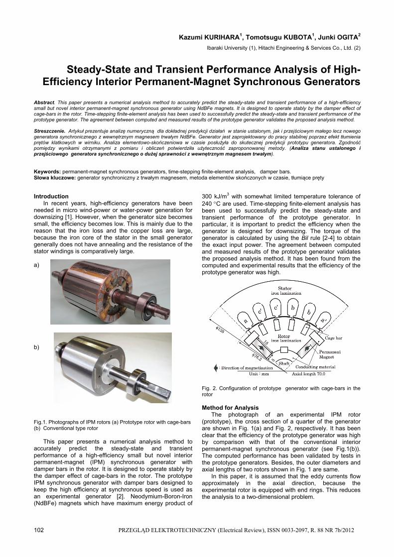
In recent years, high-efficiency generators have been needed in micro wind-power or water-power generation for downsizing [1]. However, when the generator size becomes small, the efficiency becomes low. This is mainly due to the reason that the iron loss and the copper loss are large, because the iron core of the stator in the small generator generally does not have annealing and the resistance of the stator windings is comparatively large. a) b) Fig.1. Photographs of IPM rotors (a) Prototype rotor with cage-bars (b) Conventional type rotor
This paper presents a numerical analysis method to accurately predict the steady-state and transient performance of a high-efficiency small but novel interior permanent-magnet (IPM) synchronous generator with damper bars in the rotor. It is designed to operate stably by the damper effect of cage-bars in the rotor. The prototype IPM synchronous generator with damper bars designed to keep the high efficiency at synchronous speed is used as an experimental generator [2]. Neodymium-Boron-Iron (NdBFe) magnets which have maximum energy product of
300 kJ/m3 with somewhat limited temperature tolerance of 240 C are used. Time-stepping finite-element analysis has been used to successfully predict the steady-state and transient performance of the prototype generator. In particular, it is important to predict the efficiency when the generator is designed for downsizing. The torque of the generator is calculated by using the Bil rule [2-4] to obtain the exact input power. The agreement between computed and measured results of the prototype generator validates the proposed analysis method. It has been found from the computed and experimental results that the efficiency of the prototype generator was high. Fig. 2. Configuration of prototype generator with cage-bars in the rotor Method for Analysis
The photograph of an experimental IPM rotor (prototype), the cross section of a quarter of the generator are shown in Fig. 1(a) and Fig. 2, respectively. It has been clear that the efficiency of the prototype generator was high by comparison with that of the conventional interior permanent-magnet synchronous generator (see Fig.1(b)). The computed performance has been validated by tests in the prototype generators. Besides, the outer diameters and axial lengths of two rotors shown in Fig. 1 are same.
In this paper, it is assumed that the eddy currents flow approximately in the axial direction, because the experimental rotor is equipped with end rings. This reduces the analysis to a two-dimensional problem.

PRZEGLĄD ELEKTROTECHNICZNY (Electrical Review), ISSN 0033-2097, R. 88 NR 7b/2012 103
(1) me JJJ
y
A
yx
A
x
0
(2) t
AJ e
(3)
y
M
x
MJ xym 0
where: A– z-component of magnetic vector potential A, J0 – stator-winding current density, Je – eddy current density, Jm – equivalent magnetizing current density, Mx, My– x and y components of the magnetization M, respectively [5], – conductivity, – reluctivity.
The value of in the permanent magnet is assumed the same as the reluctivity of free space 0. Jm is assumed zero outside the PM.
Fig. 3 shows the experimental circuit of the IPM generator. The three phase stator windings, which are star connected with neutral will be connected to a balanced three-phase resistance load. The voltage and current equations of the IPM synchronous generator are given as
(4) 1 1
aa a a n
ie r i L v v
t
(5) 1 1b
b b b n
ie r i L v v
t
(6) 1 1c
c c c n
ie r i L v v
t
(7) 0a b ci i i
where: ea, eb, ec –induced phase voltages, Subscripts a, b, c –subscripts of stator quantities in lines a, b, c. va, vb vc –phase voltages of balanced three-phase load, vn – potential of neutral n of three-phase load, when the potential of the neutral of the generator is zero. ia, ib ic – line currents, r1 – stator winding resistance per phase, L1 – stator end-winding leakage inductance per phase.
ea is given by the line integral of the vector potential round ca which is along the stator windings of phase a [2]
(8) a a
t t t t
a c c
A A Ae ds ds
t t
where: At –A at time t, ∆t –time step.
eb and ec can be obtained similarly, as reference in [2]. For a balanced three-phase resistance load,
(9) ,a L av R i
,b L bv R i
c L cv R i
where: RL –resistance per phase.
vn can be obtained by substituting (9) in (4)-(6), adding each side of (4)-(6) and then applying (7)
(10) 3
a b cn
e e ev
One obtains the following equation by substituting (10) in (4)-(6).
(11) 1 1
20
3 3b c a
a L a
e e ie r R i L
t
(12) 1 1
20
3 3c a b
b L b
e e ie r R i L
t
(13) 1 1
20
3 3a b c
c L c
e e ie r R i L
t
One can obtain the vector potential, currents by
assuming a constant speed and then solving (1), (11)-(13) using the time-stepping finite-element technique [2].
Next, the calculation steps for this analysis are shown in Fig. 4.
1) First, the number of revolutions per minute N, ∆t and the corresponding rotational step s are set, respectively.
2) The vector potential A at time t = 0 is set, where the static field caused by only PMs is given as the initial value.
3) At t = t + ∆t, the initial values for At, iat, ib
t and ict at new
t are set. 4) The matrix equation constructed by the time-stepping finite-element technique is solved [2].
5) The convergence of At is tested. Unless At converges, the process returns to step 4).
6) After the convergence of At, iat, ib
t and ict are obtained.
The calculation process from step 3) to 5) continues till the steady-state currents are obtained.
Fig.3. Experimental circuit of three-phase IPM synchronousgenerator
Fig. 4. Flowchart

104 PRZEGLĄD ELEKTROTECHNICZNY (Electrical Review), ISSN 0033-2097, R. 88 NR 7b/2012
Steady-state synchronous and transient performance A frame size of a 600-W three-phase four-pole Y-
connected 50Hz 200-V squirrel-cage induction motor was used for testing the three IPM rotors shown in Fig. 1. The efficiency of the experimental IPM generator is compared with that of a conventional IPM generator. It has been determined from the rated condition of the stator that the rated output power is 600W, in this paper.
Fig.5 shows the experimental setup for the experimental generator. A 2.2-kW three-phase two-pole 50-Hz 200-V squirrel-cage induction motor and a torque detector were used for measuring the efficiency of the prototype generator.
Fig. 6 shows the comparison of the load characteristics of the IPM generators with the rotors shown in Fig.1, where they have been operated at 1500 r/min by the inverter-driven induction motor. It was found from the comparison with the conventional IPM generator that the efficiency of the experimental generator was most of the same and high.
Table 1 shows the maximum output per volume of PM. It is notable that the value of the experimental generator was 31.8 W/cm3 and higher than that of conventional generator.
EMF due to PMs
Fig. 7 shows the terminal voltage waveform generated by PMs in driving the experimental IPM synchronous generators at 1500 r/min. It is shown that the agreement
between the computed and measured values of the generated voltage is excellent. Fig. 7. EMF generated by PMs Fig. 8. Computed and measured values of terminal voltage versus output Fig. 9. Computed and measured values of line current versus output
Load Performance Characteristics
Figs. 8-10 show the load performance characteristics. Fig. 8 shows the computed and measured results of the
terminal voltage versus the output. It is shown that the agreement between the computed and measured values is good. The measued values of no-load and full-load voltages were 138 V and 119 V, respectively. As a result, the voltage regulation was 16%.
Fig. 9 shows the computed and measured results of the line current versus the output. It is also shown that the agreement between the computed and measured values is good.
Fig. 10 shows the computed and measured results of the efficiency versus the output. It can be seen that the agreement between the computed and measured values is good except the range of small output. This is due to neglecting the iron loss in this analysis. Therefore, the computed values are larger than the measured ones.
Fig. 5. Experimental setup for prototype generator
50
60
70
80
90
100
0 200 400 600 800
Output (W)
Eff
icie
ncy
(%)
Experimental IPM Generator
Conventional IPM Generator
Fig. 6. Measured results of efficiency Table 1. Maximum output per volume of PM for two generators
Machine type Experimental
generator Conventional
generator
Total volume of PMs (cm3) 21.0 26.8
Maximum output (W) 667 752
Maximum output of volume of PM (W/cm3)
31.8 28.1
0
20
40
60
80
100
120
140
160
0 100 200 300 400 500 600 700Output (W)
Te
rmin
al v
olt
ag
e (
V)
Measured
Computed
0
0.5
1
1.5
2
2.5
3
3.5
4
0 100 200 300 400 500 600 700
Output (W)
Lin
e c
urr
ent (
A) Measured
Computed

PRZEGLĄD ELEKTROTECHNICZNY (Electrical Review), ISSN 0033-2097, R. 88 NR 7b/2012 105
Reasonably good agreements confirm the validity of the proposed analysis method.
Transient Performance Characteristics Fig. 11 shows the line current of the generator when a
balanced three-phase resistance load was changed from 0 to 15 Ω/phase at t = 0s. It is shown that the agreement between the computed and measured results is good. Furthr, it was found that the generator operated stable even when the load changed largely and suddenly. Reasonably good agreement in the transient performance analysis also confirms the validity of the proposed analysis method. Conclusion
The numerical analysis method to accurately predict the steady-state and transient performance of a high-efficiency small but novel interior permanent-magnet synchronous generator using NdBFe magnets has been presented. Time-stepping finite-element analysis has been used to successfully predict the steady-state and transient performance of the prototype generator. The agreement between computed and measured results of the prototype generator validates the proposed analysis method. It has been found from the computed and experimental results that the efficiency of the prototype generator was high.
REFERENCES [1] Haraguchi H., Morimoto S., Sanada M., Suitable design of a
PMSG for small-scale wind power generator, in Proc. Int. Conf .Elect. Mach. and Systems, Tokyo, Japan, Nov. 16-18, (2009)
[2] Kurihara K., Rahman M. A., High-efficiency line-start interior permanent-magnet synchronous motors, IEEE Trans. Ind. Applicat. 40 (2004), No.3, 789-796
[3] Binns K.J., Riley C.P., Wong M., The efficient evaluation of torque and field gradient in permanent-magnet machines with small air-gap, IEEE Trans. Magn. 21 (1985), 2435-2438
[4] Smith A.C., Willliamson S., Smith J.R.,Transient currents and torques in wound-rotor induction motors using the finite element method, Proc. IEE, 137 (1990), Pt. B, No.3, 160-173
[5] Nakata T., Takahashi N., Finite Element Method in Electrical Engineering, Tokyo Japan, Morikita, (1982)
[6] Binns K.J., Jabbar M.A., High-field self-start permanent magnet synchronous motor, Proc. Inst. Elect. Eng. 128 (1981), Pt. B, No. 3, 157-160
Authors: Prof. Kazumi Kurihara, Ibaraki University, Hitachi 316-8511, Japan, E-mail: [email protected]; Tomotsugu Kubota, Ibaraki University, Hitachi 316-8511, Japan, E-mail: [email protected]; Junki Ogita, Hitachi Engineering & Services Co., Ltd., Hitachi 317-0073, Japan.
The correspondence address is: e-mail: [email protected]
50
60
70
80
90
100
0 100 200 300 400 500 600 700Output (W)
Eff
icie
nc
y (%
)
Measured
Computed
Fig. 10. Computed and measured values of efficiency versusoutput
(a)
(b) Fig. 11. Measured and computed results of line current versustime (a) Measured results (b) Computed results