Embed Size (px)
Citation preview

Steady-State Engine Modeling for Calibration: A Productivity and Quality StudyMathWorks Automotive Conference 2007
Hyatt Regency, Dearborn, MIJune 20, 2007
Toyota Motor Engineering and Manufacturing, NA
Toyota Motor Corporation
A&D TechnologyIAV GmbH
Ken ButtsSatoru WatanabeJohn ReevesUlrike Schoop

June 20, 2007IAV GmbH, A&D Technology, TMC, TEMA
2
Presentation Outline
1. Motivation and Introduction
2. Advanced Calibration Process Considerations
3. Engine Test-bench Infrastructure
4. Engine Modeling: Productivity and Quality Assessment
5. Future Work
June 20, 2007IAV GmbH, A&D Technology, TMC, TEMA
3
Motivation
New powertrain technologies benefit society …
*
1. EFl : Electronic Fuel lnjection *2. VVT-i : Variable Valve Timing-intelligent *3. D-4 : Direct lnjection 4 stroke gasoline engine *4. D-4S : Direct lnjection 4 stroke gasoline engine superior version
(Source: Toyota Motor Corporation - http://www.toyota.co.jp/en/tech/environment/)
but their development carries planning implications• Complexity • Uncertainty
Engine development is already on Toyota’s critical development path !

4
Consider Engine Mapping
Engine Map: • Steady-state engine response to control inputs
– Establishes operating limits– Used to set control input bias versus operating point (steady-state calibration)
• Typically an empirical model due to accuracy requirements• Traditional Methods use Full-Factorial Experiment Design
Development Planning Implication:
2,940
26,460
238,140476,280
1
10
100
1,000
10,000
100,000
1,000,000
Base Engine12 x 7 x 7 x 5
+ Intake VVT9 levels
+ Exhaust VVT9 levels
+ Manifold Tuning2 levels
# of
Mea
sure
men
ts .
Engine technology vs. Measurement requirements
We need a different way !

June 20, 2007IAV GmbH, A&D Technology, TMC, TEMA
5
Model-based Calibration
Our Process Model :
Definition of factors
and responses
Optimization & evaluationof DoE- models
Experimental design
MBC Toolbox (TMW)
ATLAS (A&D)Measurements
on the test bench
ModelingFilling tables and fitting models of ECU
CAGE (TMW)and scripts (IAV)
X XX not considered in this presentation
Model-based Calibration Toolbox
AtlasModel-based Calibration Toolbox

June 20, 2007IAV GmbH, A&D Technology, TMC, TEMA
6
Purpose of our study
1. Investigate (and Develop where necessary) Model-based Calibration processes, methods, and tools infrastructure for engine mapping to increase productivity.
2. Quantify productivity benefit and verify quality
1. Relative to known metrics from previous production development
1. I-4 engine system with Intake VVT
2. Super-Ultra-Low-Emission-Vehicle (SULEV) emission target

June 20, 2007IAV GmbH, A&D Technology, TMC, TEMA
7
Advanced Calibration Process Considerations
1. Model Structure
2. Experiment Design
3. Model Generation
8
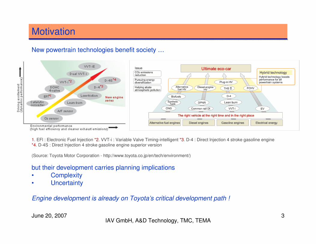
Model Structure – based on IAV experience
1. One-Stage Model
2. Engine Map is composed of five over-lapping regional models with interpolation
6000
Load
/ %
Speed / rpm
WOT
1000 2000 3000 4000 5000600
Region 1
Region 2
Region 5
Region 3
Lambda < 1 (catalyst temperature)
limited CAM timing
Region 4

June 20, 2007IAV GmbH, A&D Technology, TMC, TEMA
9
Response Models
scalingspeed, load, VVTECU calculated engine load
constraintspeed, load, VVT, λλλλ, spark timingengine roughness (COV of IMEP)
constraintspeed, load, VVT, λλλλ, spark timingHC, NOx
constraintspeed, load, VVT, λλλλ, spark timingcatalyst temperature
constraintspeed, load, VVT, λλλλ, spark timingexhaust gas temperature
constraintspeed, load, VVT, λλλλknocking limit spark timing
constraintspeed, load, VVT, λλλλMBT spark timing
optimizationspeed, load, VVT, λλλλ, spark timingCA50 (crank angle @ 50% burn)
optimizationspeed, load, VVT, λλλλ, spark timingfuel consumption
optimizationspeed, load, VVT, λλλλ, spark timingtorque
PurposeModel InputsEngine Model Output

June 20, 2007IAV GmbH, A&D Technology, TMC, TEMA
10
Method to coordinate the regional experiment designs
1. Analyze the initial preparation measurements and engineering knowledge (i.e. full load, zero torque, VVT, spark timing, and ��limits) to determine the experiment constraints for each region. –Capture these constraints in five corresponding test-plans in a single Model-Based Calibration Toolbox Project.
2. Use the Model-Based Calibration Toolbox to sequentially design an experiment for each test-plan while enforcing common measurement-points in overlapping areas.
3. Export the regional experiment designs and combine them into a single design. Sort the measurement points by speed and then load in ascending order.
4. Include repeatability measurement points at regular intervals toallow the test-automation procedures, test engineers, and modeling engineers to assess data quality.

June 20, 2007IAV GmbH, A&D Technology, TMC, TEMA
11
Experiment Regional Design Recipe
Measure the engine response at:
1. the spark timing that yields either the Maximum Brake Torque (MBT) or the engine knock limit and
2. some spark timing delta from the MBT / knock limit spark timing as scheduled by the experiment design.
Specify a 4th order polynomial with 3rd order interaction model then:
1. generate a D-optimal design with 20% more points than is minimally required. The D-optimal design gives good test coverage at the borders of the model.
2. add 20% more points with a V-optimal design. The V-optimal design adds coverage of the interior of the model.
3. add 20% more validation points with a V-optimal design. These measurements are not used for the fitting of the model.

June 20, 2007IAV GmbH, A&D Technology, TMC, TEMA
12
Model Generation Recipe
Semi-automated scripts that use the Model-Based Calibration Toolbox Command Line Interface:
1. automatically generate alternative polynomial and Radial Basis Function models that are initially evaluated based on validationRoot-Mean-Square-Error.
2. manually tune candidate polynomial models based on condition number and the effect of transformation.
3. manually inspect candidate models using single-influence plots to ensure that the responses match physical intuition.

June 20, 2007IAV GmbH, A&D Technology, TMC, TEMA
13
Engine Test-bench Infrastructure
1. Combustion analysis system to measure knock, misfire, and Coefficient of Variation of Indicated Mean Effective Pressure (COV of IMEP) .
2. Test-bench automation
3. Engine water and oil temperature conditioning
Engine Dyno.
DAC
Emissions Analyzer Prototype
ECU
CRAMAS & Rtype ECU Prototyping Tool
ASAP3 ASAP3 CAS
CAL CAL CAS
Combustion Analaysis ADAPT Data Acquisition and Control ATLAS
Calibration Tool

June 20, 2007IAV GmbH, A&D Technology, TMC, TEMA
14
Test-bench Automation using Atlas by A & D Technology
1. Atlas communicates with test-bench data-acquisition and control and engine ECU calibrations systems via ASAM standard protocols.Our set-up allowed ECU calibration command and response rates at up to 10HZ.
2. Atlas readily imports and executes experiment designs from the Model-Based Calibration Toolbox.
3. Atlas can dynamically access MATLAB for on-line data processing. We use this feature to fit a spark sweep from as few as three measurements.
4. Atlas can execute parallel threads of execution. We separate our‘engine safe operation monitor’ and our ‘test-execution’ processes into parallel, communicating execution threads.

June 20, 2007IAV GmbH, A&D Technology, TMC, TEMA
15
Test-bench Automation Example
��������������
��� ������
�������������
����������
���������
�������� ��������
���� !������
�����"�
�#$���
�#$���
%��� ���������&�'��
�#$���
��(�
(�

June 20, 2007IAV GmbH, A&D Technology, TMC, TEMA
16
Engine Modeling: Productivity
# points: X 0.17Test time: X 0.28With heaterImproved COV of IMEPAs above.
3
# points: X 0.17Test time: X 0.36As above.
General Improvements:
Parallel program.
5 dependent regions;
Overlap Commonality
2
# points: X 0.24Test time: X 0.47Heat exchanger only
Baseline;
Sequential program flow.
5 independent regions;
No overlap matching
1
# of points & Test Time (compared to baseline)
Test BenchTest AutomationExperiment DesignRun#

June 20, 2007IAV GmbH, A&D Technology, TMC, TEMA
17
Engine Modeling: Quality Assessment
0.000
2.000
4.000
6.000
8.000
10.000
Torque Fuel Flow CA50 Cat Temp In Cat Temp Rear HC NOx COV of IMEP ECU KL
Per
cent
Run2 Ave Repeatability (Std/Mean)Run2 Model Error (RMS/Range)Run3 Ave Repeatability (std/Mean)Run3 Model Error (RMSE/Range)

June 20, 2007IAV GmbH, A&D Technology, TMC, TEMA
18
Given Successful Demonstration: Future Work
1. Installation of the test-bench infrastructure in Toyota facilities for detailed evaluation.
2. Confirmation of the methods on a second engine application in close cooperation with Toyota mass-production engineers.
3. Porting the test-bench automation logic to a new Simulink / Stateflowbased test-automation environment from A&D.
4. Extending the test-bench automation methods in a general way to address more advanced engine technologies.
5. Connecting the test-automation to Toyota standard ECU communication tools.

June 20, 2007IAV GmbH, A&D Technology, TMC, TEMA
19
Acknowledgements
1. Frank Biens, Tony Gullitti, Mirko Knaak, and Karsten Roepke, (IAV).
2. Andy Hall, Brian Moore, and Ray Skinner (A&D Technology).
3. Allen Lock (Denso International of America).
4. Kotaro Tanaka, Harunaga Uozumi (Fujitsu-Ten)
5. Harufumi Muto and Masato Ehara (Toyota Motor Corporation.)