Embed Size (px)
Citation preview
S
SthcsEMsp K
1 SphcTpbawmtrsp 2 Sth
3rd International Conference ″Research and development in mechanical industry″
RaDMI 2003 19 - 23. September 2003, Herceg Novi, Serbia and Montenegro
TEAM BOILER DISPLACEMENTS AS INDICATORS FOR CORRECT PROCESS CONDUCTING
Nermina Zaimović-Uzunović1, Samir Lemeš 2, Fuad Hadžikadunić3, Nedeljko Vukojević4
1 University of Sarajevo, Faculty of Mechanical Engineering in Zenica., nzaimovic@mf-ze. unsa. ba 2 University of Sarajevo, Faculty of Mechanical Engineering in Zenica., slemes@mf-ze. unsa. ba 3 University of Sarajevo, Faculty of Mechanical Engineering in Zenica., hfuad@mf-ze. unsa. ba
4 University of Sarajevo, Faculty of Mechanical Engineering in Zenica., nvukojevic@mf-ze. unsa. ba
ummary: Steam boiler is a large industrial agregate which is very sensitive to temperature variations. In the period of work e steam production and high temperatures cause displacements of the construction. The consequences are various:
onstruction is flexibile and suspended on the springs, while large displacements lead to the cracks at the weak parts of the team boiler. In transient startup period, which can be extended on a whole day, steam boiler changes its dimensions. xtremely high elongations occur in the vertical direction, where there are no constrains. easurements of the displacements of the steam boiler were performed using telemetric equipment and displacement
ensors. The measured values discussed in this paper, are result of one-year study of the steam boiler behaviour in thermo ower plant. Results are important and were used to manage working parameters of the steam boiler.
eywords: steam boiler, displacement, measurements, thermo power plant
. INTRODUCTION
team boiler 7-230 MW is a part of thermo power plant "Kakanj" located near the town Kakanj in the centarl art of Bosnia. The power plant steam boiler has a huge dimensions. Electrical current is produced in thermo and ydro power plants which are part of interconnected system at the state level. Depending on the hydrological onditions in the region, power sources in the electrical supplying system are thermo or hydro power plants. hermo power plants are introduced in the system in a dry periods with insufficient water flow or as a common roduction systems for meeting the needs of the customers. In the period of starting up or putting out, the steam oiler construction, being discussed in this paper, is "breathing", extending or contracting. That period can be ssigned as a transient period. After that period steady state period is started and it lasts long with the full orking parameters. During the transient period many parameters, almost all technological as well as echanical, are changing through the relatively short time. All parameters have to be optimal to pass through the ansient period and successfully start the steam boiler. One of the parameters important to conduct process afely is the displacement of the boiler construction. If the displacement is large, cracks and fractures at the some laces of the steam boiler lead to the optimal process and safe steam production.
. STEAM BOILER AND ITS PARTS
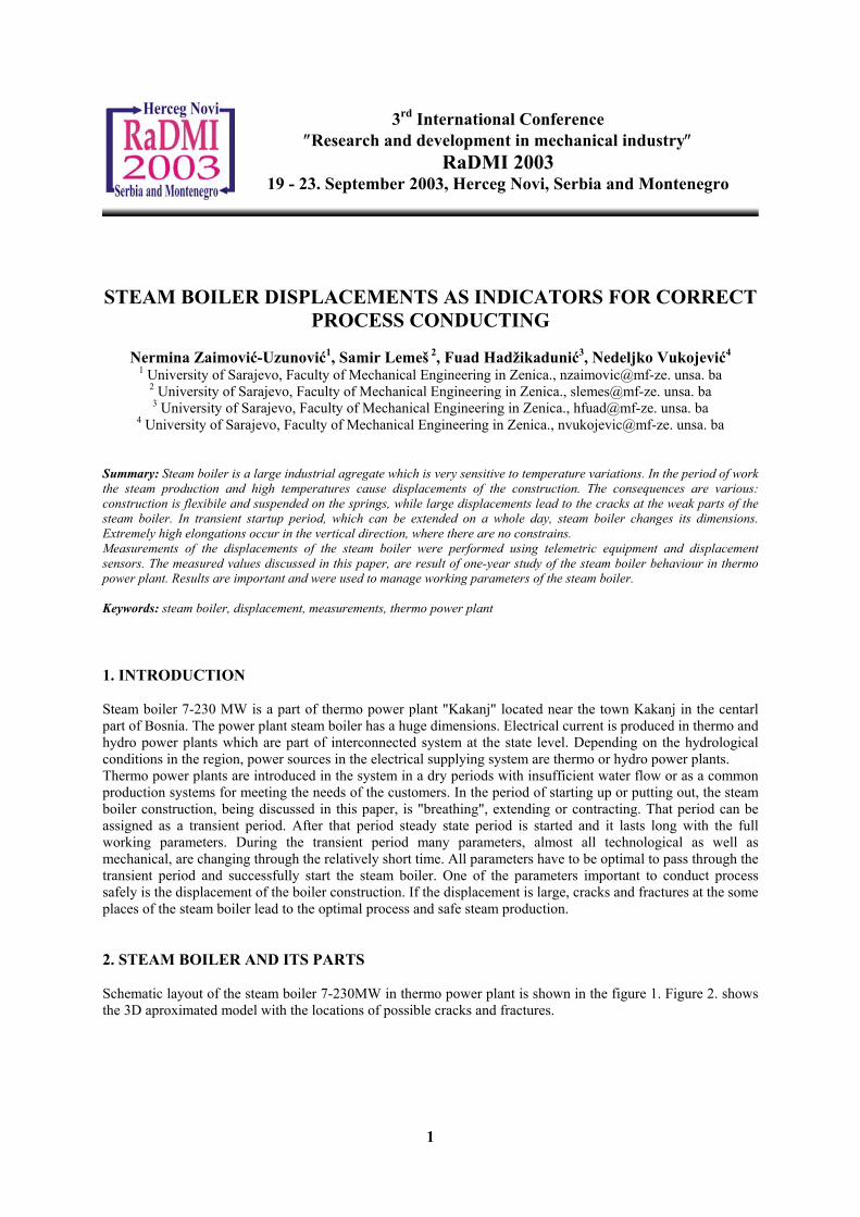
chematic layout of the steam boiler 7-230MW in thermo power plant is shown in the figure 1. Figure 2. shows e 3D aproximated model with the locations of possible cracks and fractures.
1
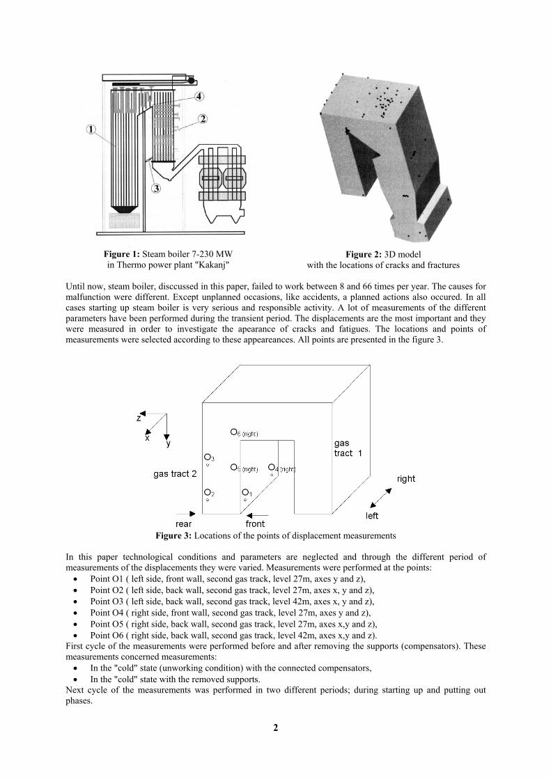
Figure 1: Steam boiler 7-230 MW in Thermo power plant "Kakanj"
Figure 2: 3D model
with the locations of cracks and fractures Until now, steam boiler, disccussed in this paper, failed to work between 8 and 66 times per year. The causes for malfunction were different. Except unplanned occasions, like accidents, a planned actions also occured. In all cases starting up steam boiler is very serious and responsible activity. A lot of measurements of the different parameters have been performed during the transient period. The displacements are the most important and they were measured in order to investigate the apearance of cracks and fatigues. The locations and points of measurements were selected according to these appeareances. All points are presented in the figure 3.
Figure 3: Locations of the points of displacement measurements
In this paper technological conditions and parameters are neglected and through the different period of measurements of the displacements they were varied. Measurements were performed at the points:
• Point O1 ( left side, front wall, second gas track, level 27m, axes y and z), • Point O2 ( left side, back wall, second gas track, level 27m, axes x, y and z), • Point O3 ( left side, back wall, second gas track, level 42m, axes x, y and z), • Point O4 ( right side, front wall, second gas track, level 27m, axes y and z), • Point O5 ( right side, back wall, second gas track, level 27m, axes x,y and z), • Point O6 ( right side, back wall, second gas track, level 42m, axes x,y and z).
First cycle of the measurements were performed before and after removing the supports (compensators). These measurements concerned measurements:
• In the "cold" state (unworking condition) with the connected compensators, • In the "cold" state with the removed supports.
Next cycle of the measurements was performed in two different periods; during starting up and putting out phases.
2
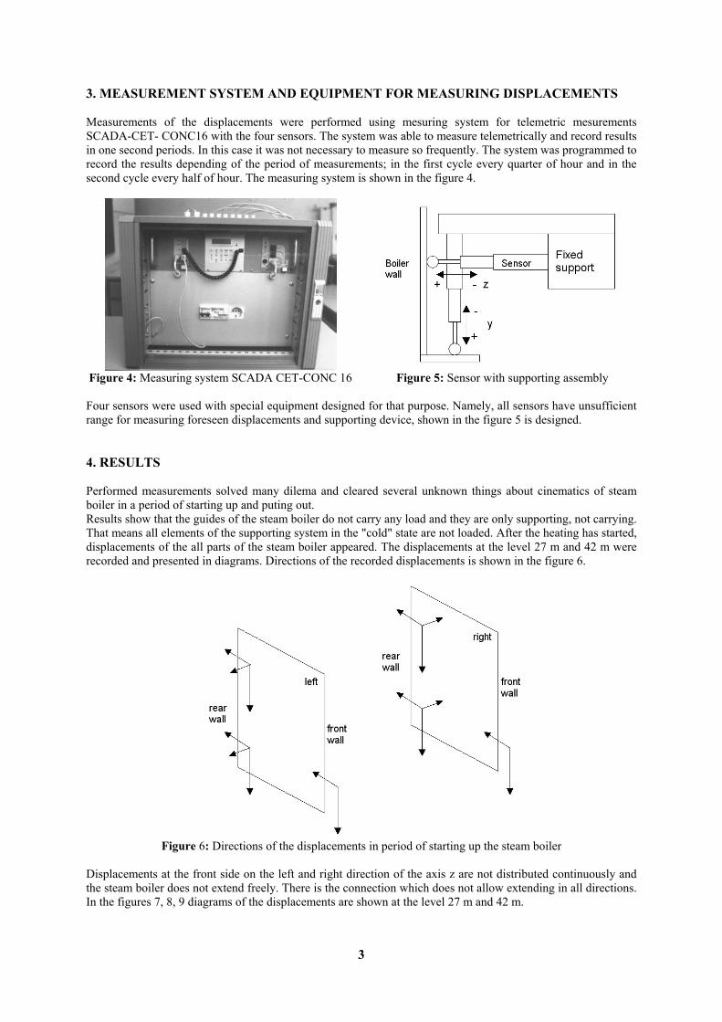
3. MEASUREMENT SYSTEM AND EQUIPMENT FOR MEASURING DISPLACEMENTS Measurements of the displacements were performed using mesuring system for telemetric mesurements SCADA-CET- CONC16 with the four sensors. The system was able to measure telemetrically and record results in one second periods. In this case it was not necessary to measure so frequently. The system was programmed to record the results depending of the period of measurements; in the first cycle every quarter of hour and in the second cycle every half of hour. The measuring system is shown in the figure 4.
Figure 4: Measuring system SCADA CET-CONC 16
Figure 5: Sensor with supporting assembly
Four sensors were used with special equipment designed for that purpose. Namely, all sensors have unsufficient range for measuring foreseen displacements and supporting device, shown in the figure 5 is designed. 4. RESULTS Performed measurements solved many dilema and cleared several unknown things about cinematics of steam boiler in a period of starting up and puting out. Results show that the guides of the steam boiler do not carry any load and they are only supporting, not carrying. That means all elements of the supporting system in the "cold" state are not loaded. After the heating has started, displacements of the all parts of the steam boiler appeared. The displacements at the level 27 m and 42 m were recorded and presented in diagrams. Directions of the recorded displacements is shown in the figure 6.
Figure 6: Directions of the displacements in period of starting up the steam boiler
Displacements at the front side on the left and right direction of the axis z are not distributed continuously and the steam boiler does not extend freely. There is the connection which does not allow extending in all directions. In the figures 7, 8, 9 diagrams of the displacements are shown at the level 27 m and 42 m.
3
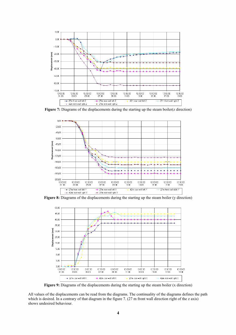
Figure 7: Diagrams of the displacements during the starting up the steam boiler(z direction)
Figure 8: Diagrams of the displacements during the starting up the steam boiler (y direction)
Figure 9: Diagrams of the displacements during the starting up the steam boiler (x direction)
All values of the displacements can be read from the diagrams. The continuality of the diagrams defines the path which is desired. In a contrary of that diagram in the figure 7. (27 m front wall direction right of the z axis) shows undesired behaviour.
4
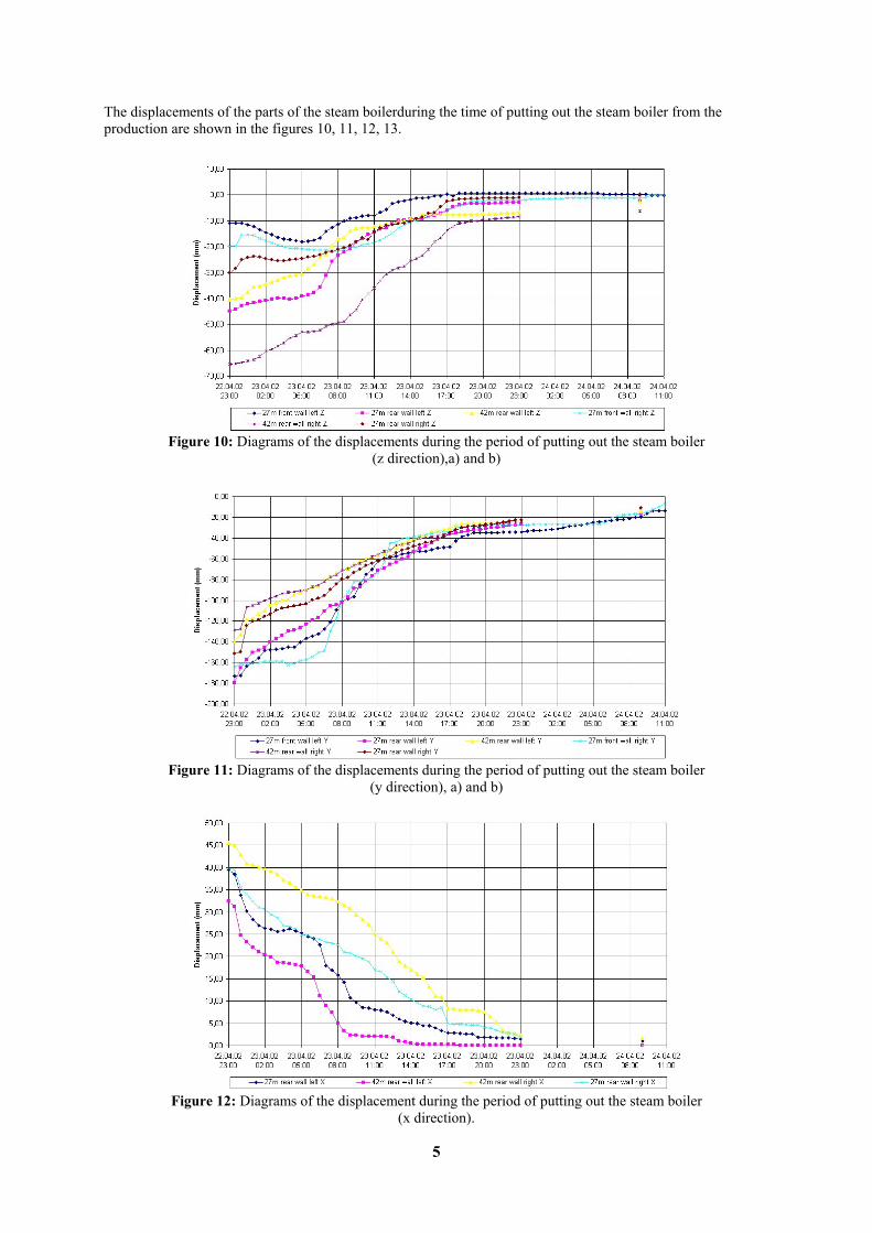
The displacements of the parts of the steam boilerduring the time of putting out the steam boiler from the production are shown in the figures 10, 11, 12, 13.
Figure 10: Diagrams of the displacements during the period of putting out the steam boiler
(z direction),a) and b)
Figure 11: Diagrams of the displacements during the period of putting out the steam boiler
(y direction), a) and b)
Figure 12: Diagrams of the displacement during the period of putting out the steam boiler
(x direction).
5
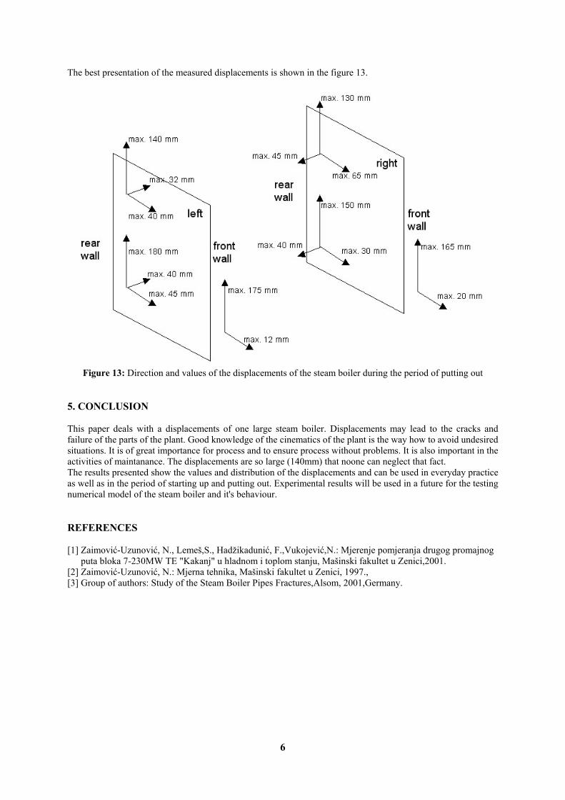
The best presentation of the measured displacements is shown in the figure 13.
Figure 13: Direction and values of the displacements of the steam boiler during the period of putting out
5. CONCLUSION This paper deals with a displacements of one large steam boiler. Displacements may lead to the cracks and failure of the parts of the plant. Good knowledge of the cinematics of the plant is the way how to avoid undesired situations. It is of great importance for process and to ensure process without problems. It is also important in the activities of maintanance. The displacements are so large (140mm) that noone can neglect that fact. The results presented show the values and distribution of the displacements and can be used in everyday practice as well as in the period of starting up and putting out. Experimental results will be used in a future for the testing numerical model of the steam boiler and it's behaviour. REFERENCES [1] Zaimović-Uzunović, N., Lemeš,S., Hadžikadunić, F.,Vukojević,N.: Mjerenje pomjeranja drugog promajnog
puta bloka 7-230MW TE "Kakanj" u hladnom i toplom stanju, Mašinski fakultet u Zenici,2001. [2] Zaimović-Uzunović, N.: Mjerna tehnika, Mašinski fakultet u Zenici, 1997., [3] Group of authors: Study of the Steam Boiler Pipes Fractures,Alsom, 2001,Germany.
6