Embed Size (px)
Citation preview
STEAM CONTROL PRODUCTSSTEAM TRAPS
Inverted BucketFloat & Thermostatic
Radiator Traps
Distributed By: M&M Control Service, Inc. www.mmcontrol.com/Sterlco.php 800-876-0036 847-356-0566
2
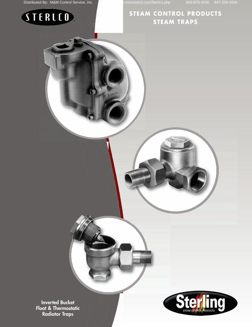
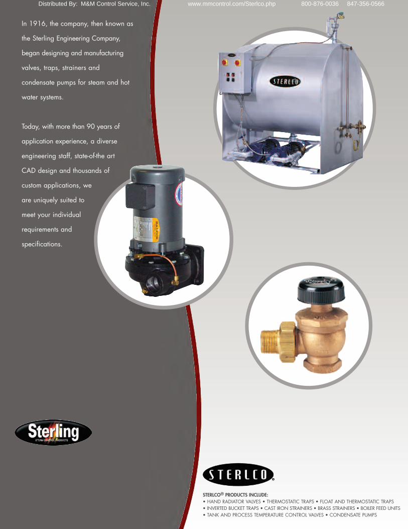
In 1916, the company, then known as the Sterling EngineeringCompany, began designing and manufacturing valves, traps,strainers and condensate pumps for steam and hot watersystems.
Today, with more than 90 years of application experience, adiverse engineering staff, state-of-the art CAD design andthousands of custom applications, we are uniquely suited to meet your individual requirements and specifications.
STEAM TRAPS
ABOUT US
3
4-5
6-9
10-13
14-15
16
17
18
Operating Fundamentals Thermostatic Radiator Traps (The Smart Trap)Float and Thermostatic Steam Traps Inverted Bucket Steam Traps (Horizontal)Inverted Bucket Steam Traps (Vertical)Application GuideEngineering DataProperties of Saturated Steam
Distributed By: M&M Control Service, Inc. www.mmcontrol.com/Sterlco.php 800-876-0036 847-356-0566
3
STEAM TRAPS
OPERATING FUNDAMENTALS
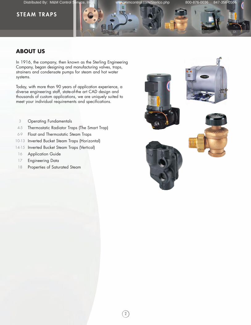
STERLCO THERMOSTATIC RADIATOR TRAPS(THE SMART TRAP)HOW THE STERLCO THERMOSTAT OPERATES
A. In a trap which is cold, or which is full ofcondensate below the boiling point, the Sterlco®thermostat remains compressed because of itsinternal vacuum. The trap is open and condensateflows out.
B. Whenever live steam strikes the bellows, thewater inside the thermostat starts to vaporize or boil.As soon as the steam pressure inside the thermostatbecomes almost equal to the steam pressuresurrounding the thermostat, the spring action of thebellows causes it to extend itself and close the trap.Because the thermostat is filled with pure water, therelationship of inside and outside pressures isalways the same. This trap will always passcondensate and hold back steam in spite of anyvariations in steam pressure.
If the thermostat is damaged, the vacuum inside willbe lost and the trap will remain closed whether it ishot or cold. The location of the trouble will be easyto find because the radiator will be cold.Meanwhile, no steam is wasted.
A B
STERLCO INVERTED BUCKET
On start up, the bucket, by its own weight, rests onthe trap bottom. The main valve is open, allowingthe discharge of air and non-condensables. Ascondensate fills the body, it creates a seal on theopen end of the bucket, which then becomesbuoyant and rises, closing the main valve.Condensate, however, continues to enter the trapand force the air within the bucket out through thevent hole, causing it to lose its buoyancy and sink,opening the main valve to discharge. Condensate isdischarged until steam reaches the trap and fills thebucket, which regains buoyancy and the operatingcycle is repeated.
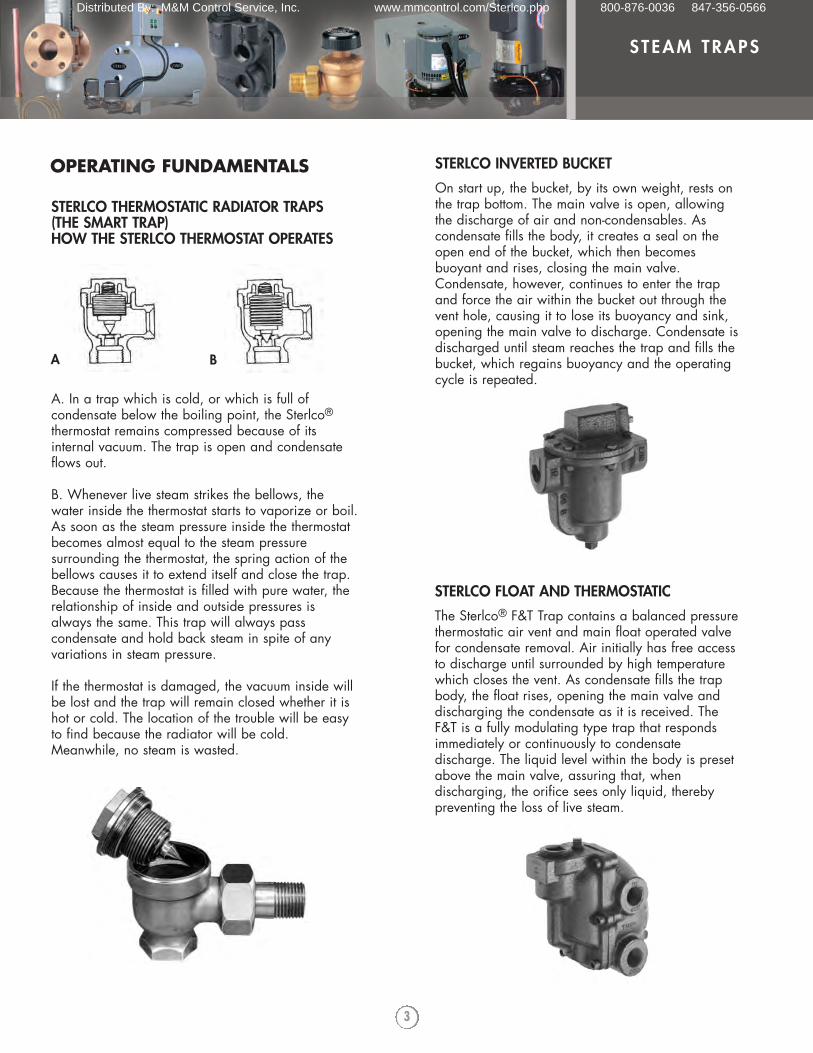
STERLCO FLOAT AND THERMOSTATIC
The Sterlco® F&T Trap contains a balanced pressurethermostatic air vent and main float operated valvefor condensate removal. Air initially has free accessto discharge until surrounded by high temperaturewhich closes the vent. As condensate fills the trapbody, the float rises, opening the main valve anddischarging the condensate as it is received. TheF&T is a fully modulating type trap that respondsimmediately or continuously to condensatedischarge. The liquid level within the body is presetabove the main valve, assuring that, whendischarging, the orifice sees only liquid, therebypreventing the loss of live steam.
Distributed By: M&M Control Service, Inc. www.mmcontrol.com/Sterlco.php 800-876-0036 847-356-0566
4
STEAM TRAPS
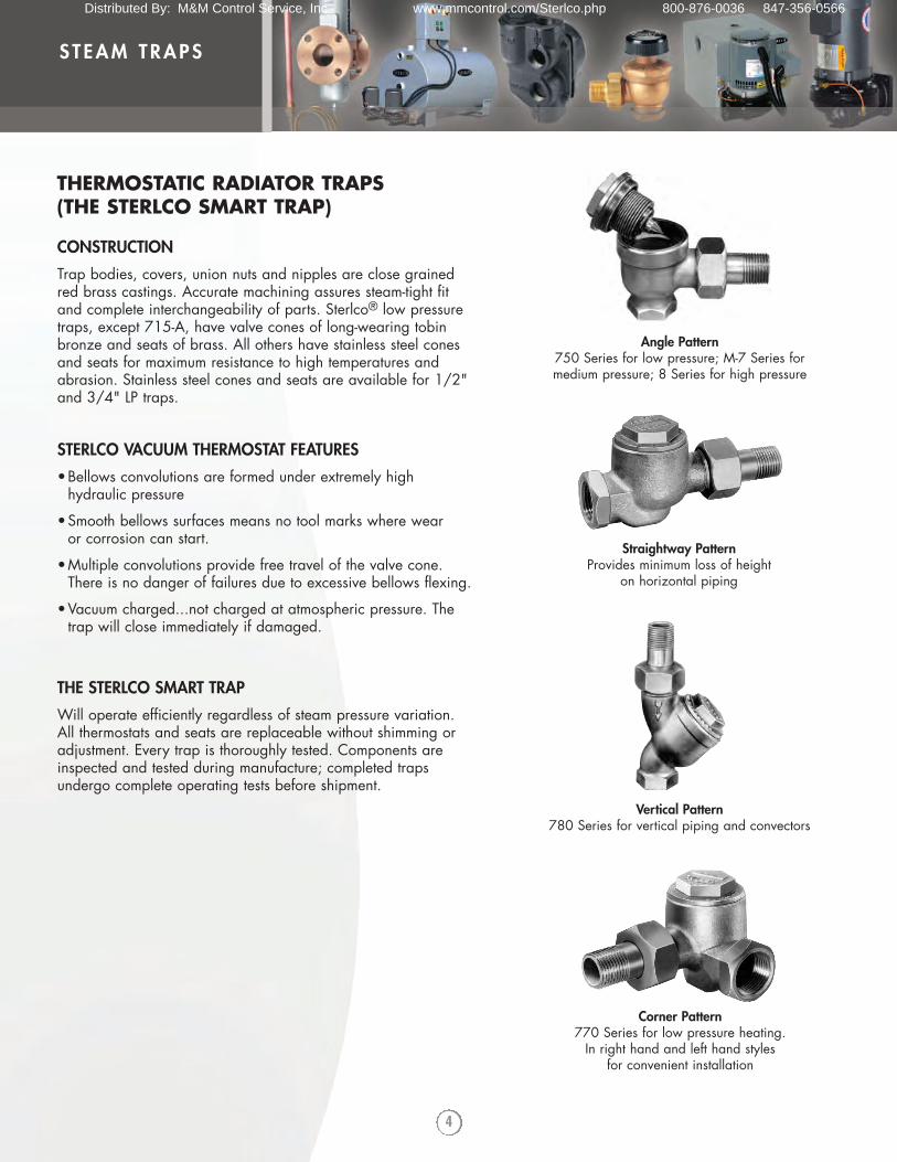
CONSTRUCTION
Trap bodies, covers, union nuts and nipples are close grainedred brass castings. Accurate machining assures steam-tight fitand complete interchangeability of parts. Sterlco® low pressuretraps, except 715-A, have valve cones of long-wearing tobinbronze and seats of brass. All others have stainless steel conesand seats for maximum resistance to high temperatures andabrasion. Stainless steel cones and seats are available for 1/2"and 3/4" LP traps.
STERLCO VACUUM THERMOSTAT FEATURES
•Bellows convolutions are formed under extremely high hydraulic pressure
•Smooth bellows surfaces means no tool marks where wear or corrosion can start.
•Multiple convolutions provide free travel of the valve cone. There is no danger of failures due to excessive bellows flexing.
•Vacuum charged...not charged at atmospheric pressure. The trap will close immediately if damaged.
THE STERLCO SMART TRAP
Will operate efficiently regardless of steam pressure variation. All thermostats and seats are replaceable without shimming oradjustment. Every trap is thoroughly tested. Components areinspected and tested during manufacture; completed trapsundergo complete operating tests before shipment.
THERMOSTATIC RADIATOR TRAPS (THE STERLCO SMART TRAP)
Angle Pattern750 Series for low pressure; M-7 Series for medium pressure; 8 Series for high pressure
Straightway PatternProvides minimum loss of height
on horizontal piping
Vertical Pattern780 Series for vertical piping and convectors
Corner Pattern770 Series for low pressure heating. In right hand and left hand styles
for convenient installation
Distributed By: M&M Control Service, Inc. www.mmcontrol.com/Sterlco.php 800-876-0036 847-356-0566
5
STEAM TRAPS
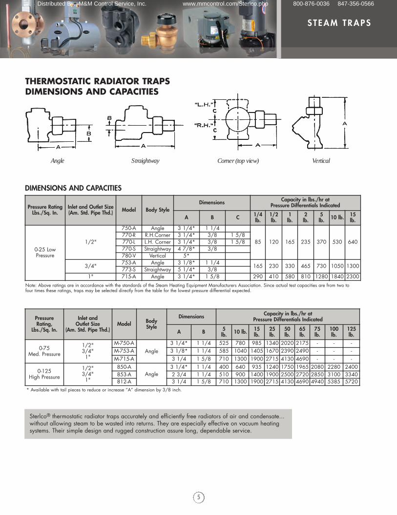
THERMOSTATIC RADIATOR TRAPSDIMENSIONS AND CAPACITIES
Pressure RatingLbs./Sq. In.
Inlet and Outlet Size(Am. Std. Pipe Thd.) Model Body Style
Dimensions Capacity in lbs./hr at Pressure Differentials Indicated
A B C 1/4lb.
1/2lb.
1lb.
2 lb.
5 lb. 10 lb. 15
lb.
0-25 LowPressure
1/2"
750-A Angle 3 1/4* 1 1/4
85 120 165 235 370 530 640770-R R.H.Corner 3 1/4* 3/8 1 5/8770-L L.H. Corner 3 1/4* 3/8 1 5/8770-S Straightway 4 7/8* 3/8780-V Vertical 5*
3/4" 753-A Angle 3 1/8* 1 1/4 165 230 330 465 730 1050 1300773-S Straightway 5 1/4* 3/81" 715-A Angle 3 1/4* 1 5/8 290 410 580 810 1280 1840 2300
DIMENSIONS AND CAPACITIES
Pressure Rating,
Lbs./Sq. In.
Inlet and Outlet Size
(Am. Std. Pipe Thd.)Model Body
Style
Dimensions Capacity in lbs./hr at Pressure Differentials Indicated
A B 5 lb. 10 lb. 15
lb.25lb.
50 lb.
65 lb.
75lb.
100lb.
125lb.
0-75 Med. Pressure
1/2"3/4"1"
M-750-AAngle
3 1/4* 1 1/4 525 780 985 1340 2020 2175 - - -M-753-A 3 1/8* 1 1/4 585 1040 1405 1670 2390 2490 - - -M-715-A 3 1/4 1 5/8 710 1300 1900 2715 4130 4690 - - -
0-125 High Pressure
1/2"3/4"1"
850-AAngle
3 1/4* 1 1/4 400 640 935 1240 1750 1965 2080 2280 2400853-A 2 3/4 1 1/4 510 900 1400 1900 2500 2720 2850 3100 3340812-A 3 1/4 1 5/8 710 1300 1900 2715 4130 4690 4940 5385 5720
Note: Above ratings are in accordance with the standards of the Steam Heating Equipment Manufacturers Association. Since actual test capacities are from two tofour times these ratings, traps may be selected directly from the table for the lowest pressure differential expected.
Angle Straightway Corner (top view) Vertical
* Available with tail pieces to reduce or increase “A” dimension by 3/8 inch.
Sterlco® thermostatic radiator traps accurately and efficiently free radiators of air and condensate...without allowing steam to be wasted into returns. They are especially effective on vacuum heating systems. Their simple design and rugged construction assure long, dependable service.
Distributed By: M&M Control Service, Inc. www.mmcontrol.com/Sterlco.php 800-876-0036 847-356-0566
6
STEAM TRAPS
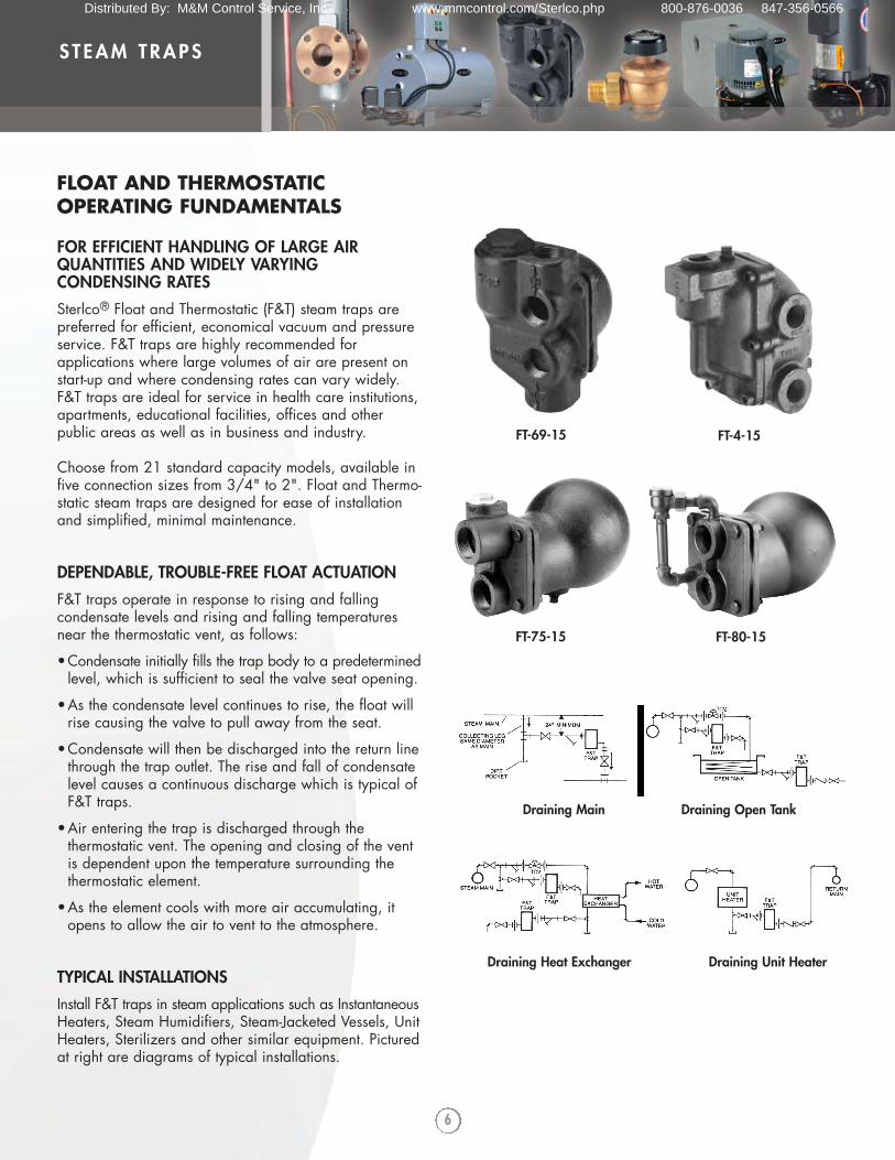
FOR EFFICIENT HANDLING OF LARGE AIRQUANTITIES AND WIDELY VARYING CONDENSING RATES
Sterlco® Float and Thermostatic (F&T) steam traps arepreferred for efficient, economical vacuum and pressureservice. F&T traps are highly recommended forapplications where large volumes of air are present onstart-up and where condensing rates can vary widely.F&T traps are ideal for service in health care institutions,apartments, educational facilities, offices and otherpublic areas as well as in business and industry.
Choose from 21 standard capacity models, available infive connection sizes from 3/4" to 2". Float and Thermo-static steam traps are designed for ease of installation and simplified, minimal maintenance.
DEPENDABLE, TROUBLE-FREE FLOAT ACTUATION
F&T traps operate in response to rising and falling condensate levels and rising and falling temperatures near the thermostatic vent, as follows:
•Condensate initially fills the trap body to a predeterminedlevel, which is sufficient to seal the valve seat opening.
•As the condensate level continues to rise, the float will rise causing the valve to pull away from the seat.
•Condensate will then be discharged into the return line through the trap outlet. The rise and fall of condensate level causes a continuous discharge which is typical of F&T traps.
•Air entering the trap is discharged through the thermostatic vent. The opening and closing of the vent is dependent upon the temperature surrounding the thermostatic element.
•As the element cools with more air accumulating, it opens to allow the air to vent to the atmosphere.
TYPICAL INSTALLATIONS
Install F&T traps in steam applications such as InstantaneousHeaters, Steam Humidifiers, Steam-Jacketed Vessels, UnitHeaters, Sterilizers and other similar equipment. Picturedat right are diagrams of typical installations.
FLOAT AND THERMOSTATIC OPERATING FUNDAMENTALS
FT-69-15
FT-80-15
FT-4-15
Draining Main Draining Open Tank
Draining Heat Exchanger Draining Unit Heater
FT-75-15
Distributed By: M&M Control Service, Inc. www.mmcontrol.com/Sterlco.php 800-876-0036 847-356-0566
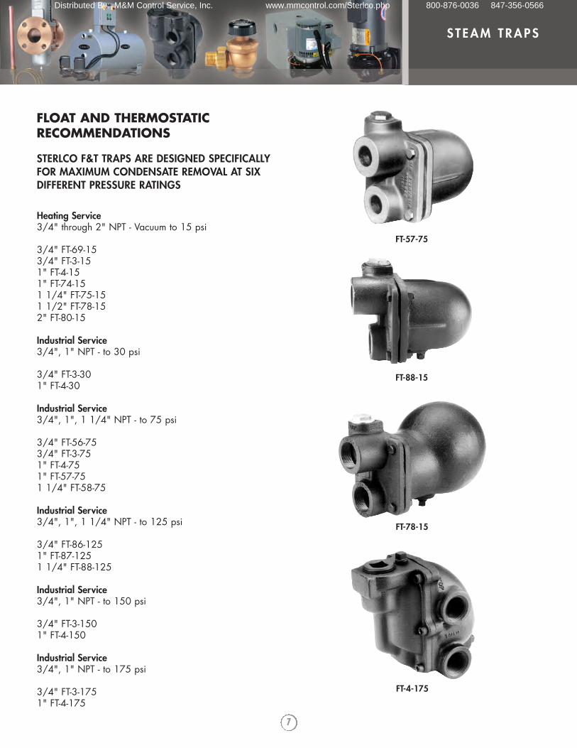
STERLCO F&T TRAPS ARE DESIGNED SPECIFICALLY FOR MAXIMUM CONDENSATE REMOVAL AT SIX DIFFERENT PRESSURE RATINGS
Heating Service3/4" through 2" NPT - Vacuum to 15 psi
3/4" FT-69-153/4" FT-3-151" FT-4-151" FT-74-151 1/4" FT-75-151 1/2" FT-78-152" FT-80-15
Industrial Service3/4", 1" NPT - to 30 psi
3/4" FT-3-301" FT-4-30
Industrial Service3/4", 1", 1 1/4" NPT - to 75 psi
3/4" FT-56-753/4" FT-3-751" FT-4-751" FT-57-751 1/4" FT-58-75
Industrial Service3/4", 1", 1 1/4" NPT - to 125 psi
3/4" FT-86-1251" FT-87-1251 1/4" FT-88-125
Industrial Service3/4", 1" NPT - to 150 psi
3/4" FT-3-1501" FT-4-150
Industrial Service3/4", 1" NPT - to 175 psi
3/4" FT-3-1751" FT-4-175
7
STEAM TRAPS
FLOAT AND THERMOSTATICRECOMMENDATIONS
FT-78-15
FT-88-15
FT-4-175
FT-57-75
Distributed By: M&M Control Service, Inc. www.mmcontrol.com/Sterlco.php 800-876-0036 847-356-0566
8
STEAM TRAPS
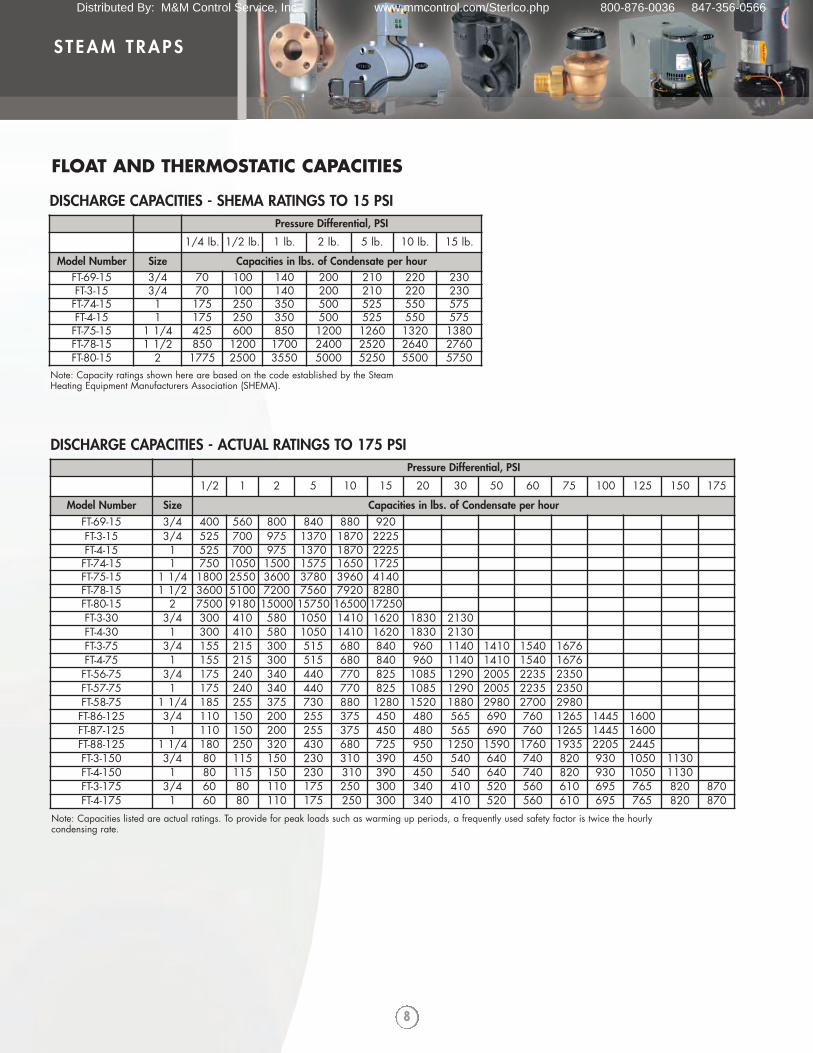
FLOAT AND THERMOSTATIC CAPACITIES
Pressure Differential, PSI
1/4 lb. 1/2 lb. 1 lb. 2 lb. 5 lb. 10 lb. 15 lb.
Model Number Size Capacities in lbs. of Condensate per hourFT-69-15 3/4 70 100 140 200 210 220 230FT-3-15 3/4 70 100 140 200 210 220 230FT-74-15 1 175 250 350 500 525 550 575FT-4-15 1 175 250 350 500 525 550 575FT-75-15 1 1/4 425 600 850 1200 1260 1320 1380FT-78-15 1 1/2 850 1200 1700 2400 2520 2640 2760FT-80-15 2 1775 2500 3550 5000 5250 5500 5750
DISCHARGE CAPACITIES - SHEMA RATINGS TO 15 PSI
Note: Capacity ratings shown here are based on the code established by the Steam Heating Equipment Manufacturers Association (SHEMA).
Pressure Differential, PSI
1/2 1 2 5 10 15 20 30 50 60 75 100 125 150 175
Model Number Size Capacities in lbs. of Condensate per hourFT-69-15 3/4 400 560 800 840 880 920FT-3-15 3/4 525 700 975 1370 1870 2225FT-4-15 1 525 700 975 1370 1870 2225FT-74-15 1 750 1050 1500 1575 1650 1725FT-75-15 1 1/4 1800 2550 3600 3780 3960 4140FT-78-15 1 1/2 3600 5100 7200 7560 7920 8280FT-80-15 2 7500 9180 15000 15750 16500 17250FT-3-30 3/4 300 410 580 1050 1410 1620 1830 2130FT-4-30 1 300 410 580 1050 1410 1620 1830 2130FT-3-75 3/4 155 215 300 515 680 840 960 1140 1410 1540 1676FT-4-75 1 155 215 300 515 680 840 960 1140 1410 1540 1676FT-56-75 3/4 175 240 340 440 770 825 1085 1290 2005 2235 2350FT-57-75 1 175 240 340 440 770 825 1085 1290 2005 2235 2350FT-58-75 1 1/4 185 255 375 730 880 1280 1520 1880 2980 2700 2980FT-86-125 3/4 110 150 200 255 375 450 480 565 690 760 1265 1445 1600FT-87-125 1 110 150 200 255 375 450 480 565 690 760 1265 1445 1600FT-88-125 1 1/4 180 250 320 430 680 725 950 1250 1590 1760 1935 2205 2445FT-3-150 3/4 80 115 150 230 310 390 450 540 640 740 820 930 1050 1130FT-4-150 1 80 115 150 230 310 390 450 540 640 740 820 930 1050 1130FT-3-175 3/4 60 80 110 175 250 300 340 410 520 560 610 695 765 820 870FT-4-175 1 60 80 110 175 250 300 340 410 520 560 610 695 765 820 870
DISCHARGE CAPACITIES - ACTUAL RATINGS TO 175 PSI
Note: Capacities listed are actual ratings. To provide for peak loads such as warming up periods, a frequently used safety factor is twice the hourlycondensing rate.
Distributed By: M&M Control Service, Inc. www.mmcontrol.com/Sterlco.php 800-876-0036 847-356-0566
9
STEAM TRAPS
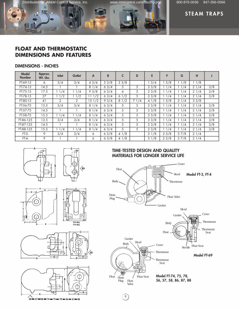
FLOAT AND THERMOSTATICDIMENSIONS AND FEATURES
ModelNumber
Approx.Wt. Lbs. Inlet Outlet A B C D E F G H J
FT-69-15 6 3/4 3/4 4 3/4 5 3/8 3 3/8 1 3/4 1 5/8 1 1/8 1 1/8FT-74-15 14.5 1 1 8 1/4 6 3/4 5 5 3 3/8 1 1/4 1 1/4 2 1/4 3/8FT-75-15 17.5 1 1/4 1 1/4 9 5/8 6 3/4 6 5 3 3/8 1 1/4 1 1/4 2 1/4 3/8FT-78-15 27 1 1/2 1 1/2 11 1/2 6 3/4 6 1/2 5 3 3/8 1 1/4 1 1/4 2 1/4 3/8FT-80-15 41 2 2 15 1/2 9 3/4 8 1/2 7 1/4 4 1/8 1 5/8 3 1/4 3 5/8FT-56-75 13.5 3/4 3/4 8 1/4 6 3/4 5 5 3 3/8 1 1/4 1 1/4 2 1/4 3/8FT-57-75 14.5 1 1 8 1/4 6 3/4 5 5 3 3/8 1 1/4 1 1/4 2 1/4 3/8FT-58-75 15.5 1 1/4 1 1/4 8 1/4 6 3/4 5 5 3 3/8 1 1/4 1 1/4 2 1/4 3/8FT-86-125 13.5 3/4 3/4 8 1/4 6 3/4 5 5 3 3/8 1 1/4 1 1/4 2 1/4 3/8FT-87-125 14.5 1 1 8 1/4 6 3/4 5 5 3 3/8 1 1/4 1 1/4 2 1/4 3/8FT-88-125 15.5 1 1/4 1 1/4 8 1/4 6 3/4 5 5 3 3/8 1 1/4 1 1/4 2 1/4 3/8
FT-3- 9 3/4 3/4 6 6 5/8 4 1/8 3 1/8 2 5/8 3 7/8 2 1/4FT-4- 9 1 1 6 6 5/8 4 1/8 3 1/8 2 5/8 3 7/8 2 1/4
DIMENSIONS - INCHES
TIME-TESTED DESIGN AND QUALITYMATERIALS FOR LONGER SERVICE LIFE
Head
Needle
ThermostatSeat
Cover
Thermostat
Float
Body
Gasket
GasketHead
Cover
Thermostat
ThermostatSeat
Float SeatFloat Valve
Float DrainPlug
Body
Float
Body
Cover
Head
Thermostat
Float Valve
Gasket
DrainPlug
Float Seat
Model FT-3, FT-4
Model FT-69
Model FT-74, 75, 78,56, 57, 58, 86, 87, 88
Distributed By: M&M Control Service, Inc. www.mmcontrol.com/Sterlco.php 800-876-0036 847-356-0566
10
STEAM TRAPS
Outlet1/2" or 3/4" NPT
Drain Plug1/2" NPT
Inlet1/2" or 3/4" NPT
StrainerSS Screen
Cast Iron CoverASTM A278 CL30
Cover GasketNon-Asbestos
Cast Iron BodyASTM A278 CL30
Guide Tube AssemblyTube: 304 SSScreen: SSRetainer: SS
4 Cover BoltsGrade 5
Valve AssemblySeat: 420 SSDisc: 420 SSLever: 302 SSDisc Lock: 304 SSClevis: 302 SS
Bucket AssemblyShell: 304 SSTube: 304 SSClevis: 302 SS
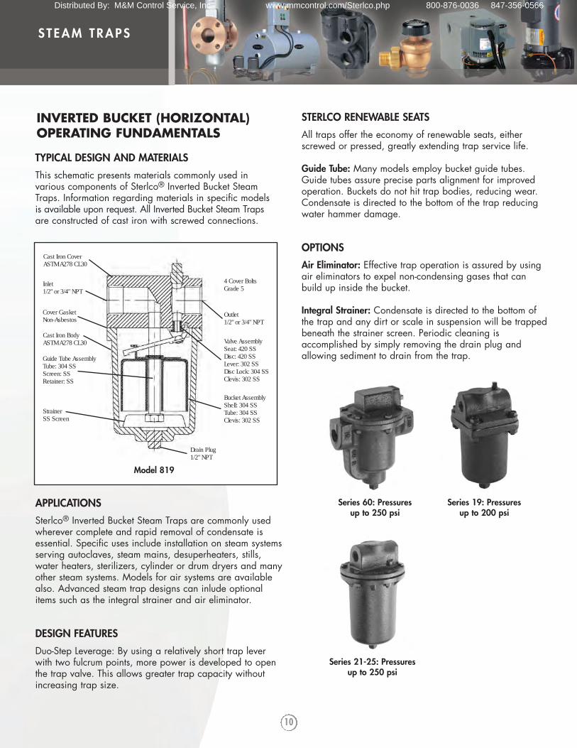
Model 819
INVERTED BUCKET (HORIZONTAL)OPERATING FUNDAMENTALS
TYPICAL DESIGN AND MATERIALS
This schematic presents materials commonly used invarious components of Sterlco® Inverted Bucket SteamTraps. Information regarding materials in specific modelsis available upon request. All Inverted Bucket Steam Trapsare constructed of cast iron with screwed connections.
APPLICATIONS
Sterlco® Inverted Bucket Steam Traps are commonly usedwherever complete and rapid removal of condensate isessential. Specific uses include installation on steam systemsserving autoclaves, steam mains, desuperheaters, stills,water heaters, sterilizers, cylinder or drum dryers and manyother steam systems. Models for air systems are availablealso. Advanced steam trap designs can inlude optionalitems such as the integral strainer and air eliminator.
DESIGN FEATURES
Duo-Step Leverage: By using a relatively short trap leverwith two fulcrum points, more power is developed to openthe trap valve. This allows greater trap capacity withoutincreasing trap size.
STERLCO RENEWABLE SEATS
All traps offer the economy of renewable seats, eitherscrewed or pressed, greatly extending trap service life.
Guide Tube: Many models employ bucket guide tubes.Guide tubes assure precise parts alignment for improvedoperation. Buckets do not hit trap bodies, reducing wear.Condensate is directed to the bottom of the trap reducingwater hammer damage.
OPTIONS
Air Eliminator: Effective trap operation is assured by usingair eliminators to expel non-condensing gases that canbuild up inside the bucket.
Integral Strainer: Condensate is directed to the bottom ofthe trap and any dirt or scale in suspension will be trappedbeneath the strainer screen. Periodic cleaning isaccomplished by simply removing the drain plug andallowing sediment to drain from the trap.
Series 60: Pressuresup to 250 psi
Series 19: Pressuresup to 200 psi
Series 21-25: Pressuresup to 250 psi
Distributed By: M&M Control Service, Inc. www.mmcontrol.com/Sterlco.php 800-876-0036 847-356-0566
11
STEAM TRAPS
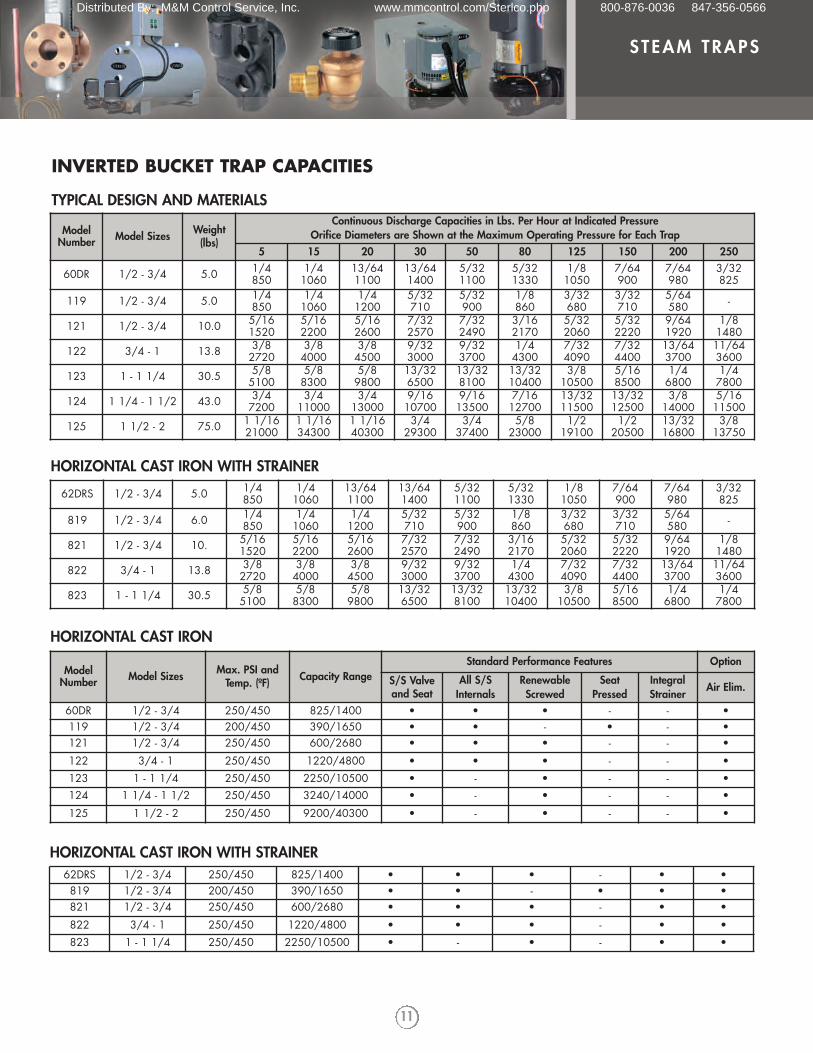
ModelNumber Model Sizes Weight
(lbs)
Continuous Discharge Capacities in Lbs. Per Hour at Indicated PressureOrifice Diameters are Shown at the Maximum Operating Pressure for Each Trap
5 15 20 30 50 80 125 150 200 250
60DR 1/2 - 3/4 5.0 1/4850
1/41060
13/641100
13/641400
5/321100
5/321330
1/81050
7/64900
7/64980
3/32825
119 1/2 - 3/4 5.0 1/4850
1/41060
1/41200
5/32710
5/32900
1/8860
3/32680
3/32710
5/64580 -
121 1/2 - 3/4 10.0 5/161520
5/162200
5/162600
7/322570
7/322490
3/162170
5/322060
5/322220
9/641920
1/81480
122 3/4 - 1 13.8 3/82720
3/84000
3/84500
9/323000
9/323700
1/44300
7/324090
7/324400
13/643700
11/643600
123 1 - 1 1/4 30.5 5/85100
5/88300
5/89800
13/326500
13/328100
13/3210400
3/810500
5/168500
1/46800
1/47800
124 1 1/4 - 1 1/2 43.0 3/47200
3/411000
3/413000
9/1610700
9/1613500
7/1612700
13/3211500
13/3212500
3/814000
5/1611500
125 1 1/2 - 2 75.0 1 1/1621000
1 1/1634300
1 1/1640300
3/429300
3/437400
5/823000
1/219100
1/220500
13/3216800
3/813750
62DRS 1/2 - 3/4 5.0 1/4850
1/41060
13/641100
13/641400
5/321100
5/321330
1/81050
7/64900
7/64980
3/32825
819 1/2 - 3/4 6.0 1/4850
1/41060
1/41200
5/32710
5/32900
1/8860
3/32680
3/32710
5/64580 -
821 1/2 - 3/4 10. 5/161520
5/162200
5/162600
7/322570
7/322490
3/162170
5/322060
5/322220
9/641920
1/81480
822 3/4 - 1 13.8 3/82720
3/84000
3/84500
9/323000
9/323700
1/44300
7/324090
7/324400
13/643700
11/643600
823 1 - 1 1/4 30.5 5/85100
5/88300
5/89800
13/326500
13/328100
13/3210400
3/810500
5/168500
1/46800
1/47800
HORIZONTAL CAST IRON WITH STRAINER
ModelNumber Model Sizes Max. PSI and
Temp. (ºF) Capacity RangeStandard Performance Features Option
S/S Valveand Seat
All S/SInternals
RenewableScrewed
SeatPressed
IntegralStrainer
Air Elim.
60DR 1/2 - 3/4 250/450 825/1400 • • • - - •119 1/2 - 3/4 200/450 390/1650 • • - • - •121 1/2 - 3/4 250/450 600/2680 • • • - - •122 3/4 - 1 250/450 1220/4800 • • • - - •123 1 - 1 1/4 250/450 2250/10500 • - • - - •124 1 1/4 - 1 1/2 250/450 3240/14000 • - • - - •
125 1 1/2 - 2 250/450 9200/40300 • - • - - •
HORIZONTAL CAST IRON
62DRS 1/2 - 3/4 250/450 825/1400 • • • - • •819 1/2 - 3/4 200/450 390/1650 • • - • • •821 1/2 - 3/4 250/450 600/2680 • • • - • •822 3/4 - 1 250/450 1220/4800 • • • - • •823 1 - 1 1/4 250/450 2250/10500 • - • - • •
HORIZONTAL CAST IRON WITH STRAINER
INVERTED BUCKET TRAP CAPACITIES
TYPICAL DESIGN AND MATERIALS
Distributed By: M&M Control Service, Inc. www.mmcontrol.com/Sterlco.php 800-876-0036 847-356-0566
12
STEAM TRAPS
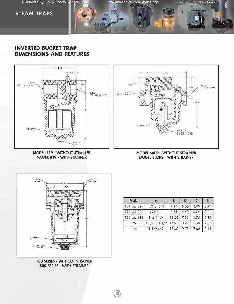
MODEL 119 - WITHOUT STRAINERMODEL 819 - WITH STRAINER
MODEL 60DR - WITHOUT STRAINERMODEL 60DRS - WITH STRAINER
100 SERIES - WITHOUT STRAINER800 SERIES - WITH STRAINER
Model A B C D E
121 and 821 1/2 or 3/4 7.25 5.00 3.00 0.97
122 and 822 3/4 or 1 8.75 5.50 3.75 0.91
123 and 823 1 or 1 1/4 12.50 7.38 4.75 2.25
124 1 1/4 or 1 1/2 14.95 8.25 5.50 2.38
125 1 1/2 or 2 17.40 9.75 7.00 3.13
INVERTED BUCKET TRAP DIMENSIONS AND FEATURES
Distributed By: M&M Control Service, Inc. www.mmcontrol.com/Sterlco.php 800-876-0036 847-356-0566
13
STEAM TRAPS
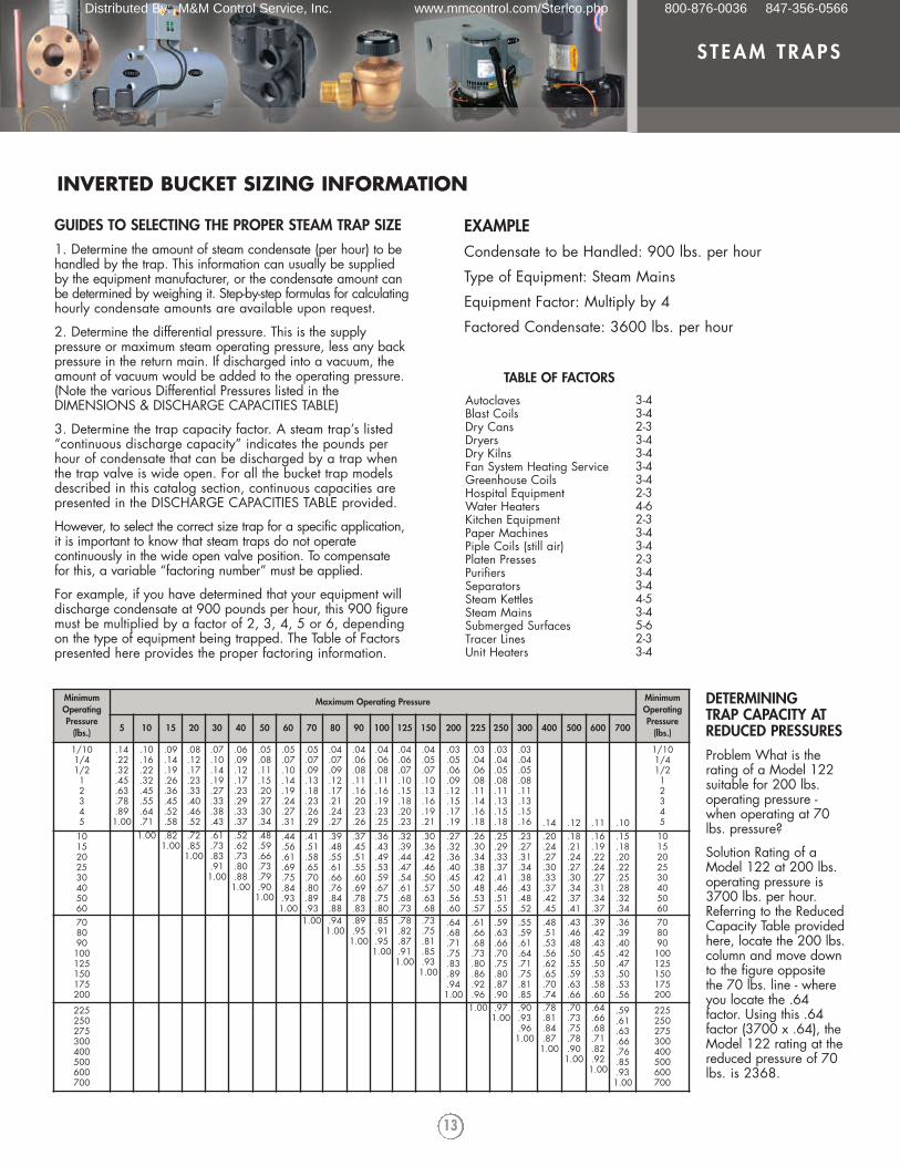
EXAMPLECondensate to be Handled: 900 lbs. per hour
Type of Equipment: Steam Mains
Equipment Factor: Multiply by 4
Factored Condensate: 3600 lbs. per hour
MinimumOperatingPressure
(lbs.)
Maximum Operating Pressure MinimumOperatingPressure
(lbs.)5 10 15 20 30 40 50 60 70 80 90 100 125 150 200 225 250 300 400 500 600 700
1/101/41/212345
.14
.22
.32
.45
.63
.78
.891.00
.10
.16
.22
.32
.45
.55
.64
.71
.09
.14
.19
.26
.36
.45
.52
.58
.08
.12
.17
.23
.33
.40
.46
.52
.07
.10
.14
.19
.27
.33
.38
.43
.06
.09
.12
.17
.23
.29
.33
.37
.05
.08
.11
.15
.20
.27
.30
.34
.05
.07
.10
.14
.19
.24
.27
.31
.05
.07
.09
.13
.18
.23
.26
.29
.04
.07
.09
.12
.17
.21
.24
.27
.04
.06
.08
.11
.16
.20
.23
.26
.04
.06
.08
.11
.16
.19
.23
.25
.04
.06
.07
.10
.15
.18
.20
.23
.04
.05
.07
.10
.13
.16
.19
.21
.03
.05
.06
.09
.12
.15
.17
.19
.03
.04
.06
.08
.11
.14
.16
.18
.03
.04
.05
.08
.11
.13
.15
.18
.03
.04
.05
.08
.11
.13
.15
.16 .14 .12 .11 .10
1/101/41/212345
1015202530405060
1.00 .821.00
.72
.851.00
.61
.73
.83
.911.00
.52
.62
.73
.80
.881.00
.48
.59
.66
.73
.79
.901.00
.44
.56
.61
.69
.75
.84
.931.00
.41
.51
.58
.65
.70
.80
.89
.93
.39
.48
.55
.61
.66
.76
.84
.88
.37
.45
.51
.55
.60
.69
.78
.83
.36
.43
.49
.53
.59
.67
.75
.80
.32
.39
.44
.47
.54
.61
.68
.73
.30
.36
.42
.46
.50
.57
.63
.68
.27
.32
.36
.40
.45
.50
.56
.60
.26
.30
.34
.38
.42
.48
.53
.57
.25
.29
.33
.37
.41
.46
.51
.55
.23
.27
.31
.34
.38
.43
.48
.52
.20
.24
.27
.30
.33
.37
.42
.45
.18
.21
.24
.27
.30
.34
.37
.41
.16
.19
.22
.24
.27
.31
.34
.37
.15
.18
.20
.22
.25
.28
.32
.34
1015202530405060
708090100125150175200
1.00 .941.00
.89
.951.00
.85
.91
.951.00
.78
.82
.87
.911.00
.73
.75
.81
.85
.931.00
.64
.68
.71
.75
.83
.89
.941.00
.61
.66
.68
.73
.80
.86
.92
.96
.59
.63
.66
.70
.75
.80
.87
.90
.55
.59
.61
.64
.71
.75
.81
.85
.48
.51
.53
.56
.62
.65
.70
.74
.43
.46
.48
.50
.55
.59
.63
.66
.39
.42
.43
.45
.50
.53
.58
.60
.36
.39
.40
.42
.47
.50
.53
.56
708090100125150175200
225250275300400500600700
1.00 .971.00
.90
.93
.961.00
.78
.81
.84
.871.00
.70
.73
.75
.78
.901.00
.64
.66
.68
.71
.82
.921.00
.59
.61
.63
.66
.76
.85
.931.00
225250275300400500600700
TABLE OF FACTORS
AutoclavesBlast CoilsDry CansDryersDry KilnsFan System Heating ServiceGreenhouse CoilsHospital EquipmentWater HeatersKitchen EquipmentPaper MachinesPiple Coils (still air)Platen PressesPurifiersSeparatorsSteam KettlesSteam MainsSubmerged SurfacesTracer LinesUnit Heaters
3-43-42-33-43-43-43-42-34-62-33-43-42-33-43-44-53-45-62-33-4
DETERMINING TRAP CAPACITY ATREDUCED PRESSURESProblem What is therating of a Model 122suitable for 200 lbs.operating pressure -when operating at 70lbs. pressure?
Solution Rating of aModel 122 at 200 lbs.operating pressure is3700 lbs. per hour.Referring to the ReducedCapacity Table providedhere, locate the 200 lbs.column and move downto the figure oppositethe 70 lbs. line - whereyou locate the .64factor. Using this .64factor (3700 x .64), theModel 122 rating at thereduced pressure of 70lbs. is 2368.
INVERTED BUCKET SIZING INFORMATION
GUIDES TO SELECTING THE PROPER STEAM TRAP SIZE1. Determine the amount of steam condensate (per hour) to behandled by the trap. This information can usually be suppliedby the equipment manufacturer, or the condensate amount canbe determined by weighing it. Step-by-step formulas for calculatinghourly condensate amounts are available upon request.
2. Determine the differential pressure. This is the supplypressure or maximum steam operating pressure, less any backpressure in the return main. If discharged into a vacuum, theamount of vacuum would be added to the operating pressure.(Note the various Differential Pressures listed in theDIMENSIONS & DISCHARGE CAPACITIES TABLE)
3. Determine the trap capacity factor. A steam trap’s listed“continuous discharge capacity” indicates the pounds perhour of condensate that can be discharged by a trap whenthe trap valve is wide open. For all the bucket trap modelsdescribed in this catalog section, continuous capacities arepresented in the DISCHARGE CAPACITIES TABLE provided.
However, to select the correct size trap for a specific application,it is important to know that steam traps do not operatecontinuously in the wide open valve position. To compensatefor this, a variable “factoring number” must be applied.
For example, if you have determined that your equipment willdischarge condensate at 900 pounds per hour, this 900 figuremust be multiplied by a factor of 2, 3, 4, 5 or 6, dependingon the type of equipment being trapped. The Table of Factorspresented here provides the proper factoring information.
Distributed By: M&M Control Service, Inc. www.mmcontrol.com/Sterlco.php 800-876-0036 847-356-0566
14
STEAM TRAPS
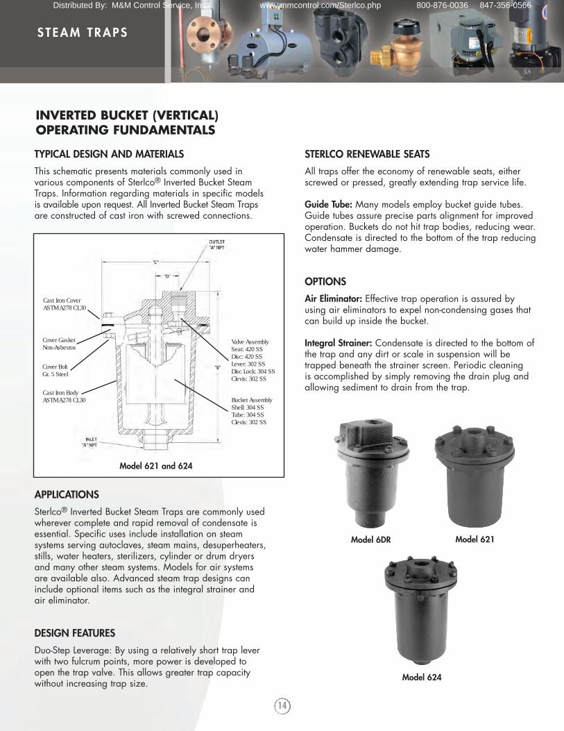
Model 624
Model 6DR Model 621
INVERTED BUCKET (VERTICAL) OPERATING FUNDAMENTALS
TYPICAL DESIGN AND MATERIALS
This schematic presents materials commonly used invarious components of Sterlco® Inverted Bucket SteamTraps. Information regarding materials in specific modelsis available upon request. All Inverted Bucket Steam Trapsare constructed of cast iron with screwed connections.
APPLICATIONS
Sterlco® Inverted Bucket Steam Traps are commonly usedwherever complete and rapid removal of condensate isessential. Specific uses include installation on steamsystems serving autoclaves, steam mains, desuperheaters,stills, water heaters, sterilizers, cylinder or drum dryersand many other steam systems. Models for air systemsare available also. Advanced steam trap designs caninclude optional items such as the integral strainer andair eliminator.
DESIGN FEATURES
Duo-Step Leverage: By using a relatively short trap leverwith two fulcrum points, more power is developed toopen the trap valve. This allows greater trap capacitywithout increasing trap size.
Cast Iron CoverASTM A278 CL30
Cover GasketNon-Asbestos
Cast Iron BodyASTM A278 CL30
Valve AssemblySeat: 420 SSDisc: 420 SSLever: 302 SSDisc Lock: 304 SSClevis: 302 SS
Bucket AssemblyShell: 304 SSTube: 304 SSClevis: 302 SS
Cover BoltGr. 5 Steel
Model 621 and 624
STERLCO RENEWABLE SEATS
All traps offer the economy of renewable seats, eitherscrewed or pressed, greatly extending trap service life.
Guide Tube: Many models employ bucket guide tubes.Guide tubes assure precise parts alignment for improvedoperation. Buckets do not hit trap bodies, reducing wear.Condensate is directed to the bottom of the trap reducingwater hammer damage.
OPTIONS
Air Eliminator: Effective trap operation is assured byusing air eliminators to expel non-condensing gases thatcan build up inside the bucket.
Integral Strainer: Condensate is directed to the bottom ofthe trap and any dirt or scale in suspension will betrapped beneath the strainer screen. Periodic cleaning is accomplished by simply removing the drain plug andallowing sediment to drain from the trap.
Distributed By: M&M Control Service, Inc. www.mmcontrol.com/Sterlco.php 800-876-0036 847-356-0566
15
STEAM TRAPS
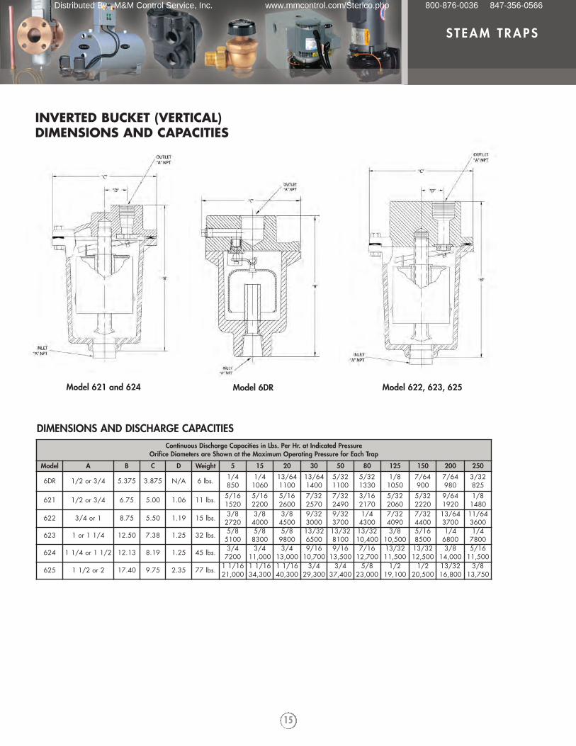
Continuous Discharge Capacities in Lbs. Per Hr. at Indicated PressureOrifice Diameters are Shown at the Maximum Operating Pressure for Each Trap
Model A B C D Weight 5 15 20 30 50 80 125 150 200 250
6DR 1/2 or 3/4 5.375 3.875 N/A 6 lbs. 1/4850
1/41060
13/641100
13/641400
5/321100
5/321330
1/81050
7/64900
7/64980
3/32825
621 1/2 or 3/4 6.75 5.00 1.06 11 lbs. 5/161520
5/162200
5/162600
7/322570
7/322490
3/162170
5/322060
5/322220
9/641920
1/81480
622 3/4 or 1 8.75 5.50 1.19 15 lbs. 3/82720
3/84000
3/84500
9/323000
9/323700
1/44300
7/324090
7/324400
13/643700
11/643600
623 1 or 1 1/4 12.50 7.38 1.25 32 lbs. 5/85100
5/88300
5/89800
13/326500
13/328100
13/3210,400
3/810,500
5/168500
1/46800
1/47800
624 1 1/4 or 1 1/2 12.13 8.19 1.25 45 lbs. 3/47200
3/411,000
3/413,000
9/1610,700
9/1613,500
7/1612,700
13/3211,500
13/3212,500
3/814,000
5/1611,500
625 1 1/2 or 2 17.40 9.75 2.35 77 lbs. 1 1/1621,000
1 1/1634,300
1 1/1640,300
3/429,300
3/437,400
5/823,000
1/219,100
1/220,500
13/3216,800
3/813,750
DIMENSIONS AND DISCHARGE CAPACITIES
Model 621 and 624 Model 622, 623, 625Model 6DR
INVERTED BUCKET (VERTICAL) DIMENSIONS AND CAPACITIES
Distributed By: M&M Control Service, Inc. www.mmcontrol.com/Sterlco.php 800-876-0036 847-356-0566
16
STEAM TRAPS
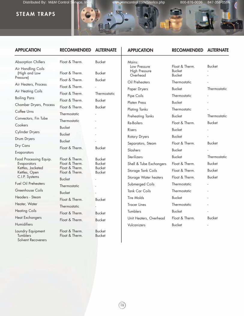
APPLICATION
Absorption Chillers
Air Handling Coils (High and Low
Pressure)
Air Heaters, Process
Air Heating Coils
Boiling Pans
Chamber Dryers, Process
Coffee Urns
Convectors, Fin Tube
Cookers
Cylinder Dryers
Drum Dryers
Dry Cans
Evaporators
Food Processing Equip.EvaporatorsKettles, JacketedKettles, OpenC.I.P. Systems
Fuel Oil Preheaters
Greenhouse Coils
Headers - Steam
Heater, Water
Heating Coils
Heat Exchangers
Humidifiers
Laundry EquipmentTumblersSolvent Recoverers
RECOMMENDED
Float & Therm.
Float & Therm.
Float & Therm.
Float & Therm.
Float & Therm.
Float & Therm.
Float & Therm.
Thermostatic
Thermostatic
Bucket
Bucket
Bucket
Float & Therm.
Float & Therm.Float & Therm.Float & Therm.Float & Therm.
Bucket
Thermostatic
Bucket
Float & Therm.
Thermostatic
Float & Therm.
Float & Therm.
Float & Therm.Float & Therm.
ALTERNATE
Bucket
Bucket
Bucket
-
Thermostatic
Bucket
Bucket
-
-
-
-
-
Bucket
BucketBucketBucketBucket
-
-
-
Bucket
-
Bucket
Bucket
BucketBucket
APPLICATION
Mains:Low PressureHigh PressureOverhead
Oil Preheaters
Paper Dryers
Pipe Coils
Platen Press
Plating Tanks
Preheating Tanks
Re-Boilers
Risers
Rotary Dryers
Separators, Steam
Slashers
Sterilizers
Shell & Tube Exchangers
Storage Tank Coils
Storage Water heaters
Submerged Coils
Tank Car Coils
Tire Molds
Tracer Lines
Tumblers
Unit Heaters, Overhead
Vulcanizers
RECOMMENDED
Float & Therm.BucketBucket
Thermostatic
Bucket
Thermostatic
Bucket
Thermostatic
Bucket
Float & Therm.
Bucket
Bucket
Float & Therm.
Bucket
Bucket
Float & Therm.
Float & Therm.
Float & Therm.
Thermostatic
Thermostatic
Bucket
Thermostatic
Bucket
Float & Therm.
Bucket
ALTERNATE
Bucket--
-
Thermostatic
-
-
-
Thermostatic
Bucket
-
-
Bucket
-
Thermostatic
Bucket
Bucket
Bucket
-
-
-
-
-
Bucket
-
Distributed By: M&M Control Service, Inc. www.mmcontrol.com/Sterlco.php 800-876-0036 847-356-0566
17
STEAM TRAPS
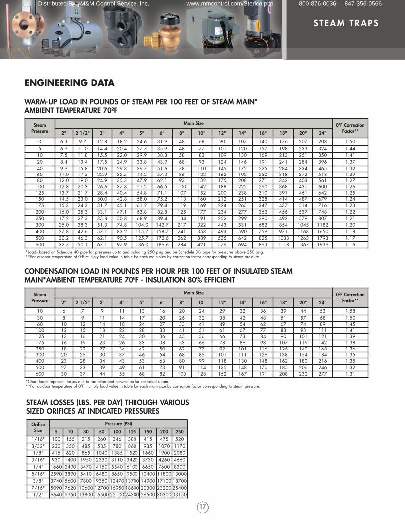
SteamPressure
Main Size 0ºF CorrectionFactor**2" 2 1/2" 3" 4" 5" 6" 8" 10" 12" 14" 16" 18" 20" 24"
0 6.3 9.7 12.8 18.2 24.6 31.9 48 68 90 107 140 176 207 208 1.505 6.9 11.0 14.4 20.4 27.7 35.9 48 77 101 120 157 198 233 324 1.4410 7.5 11.8 15.5 22.0 29.9 38.8 58 83 109 130 169 213 251 350 1.4120 8.4 13.4 17.5 24.9 33.8 43.9 68 93 124 146 191 241 284 396 1.3740 9.9 15.8 20.6 29.3 39.7 51.6 78 110 145 172 225 284 334 465 1.3260 11.0 17.5 22.9 32.5 44.2 57.3 86 122 162 192 250 318 372 518 1.2980 12.0 19.0 24.9 35.3 47.9 62.1 93 132 175 208 271 342 403 561 1.27100 12.8 20.3 26.6 37.8 51.2 66.5 100 142 188 222 290 368 431 600 1.26125 13.7 21.7 28.4 40.4 54.8 71.1 107 152 200 238 310 391 461 642 1.25150 14.5 23.0 30.0 42.8 58.0 75.2 113 160 212 251 328 414 487 679 1.24175 15.3 24.2 31.7 45.1 61.2 79.4 119 169 224 265 347 437 514 716 1.23200 16.0 25.3 33.1 47.1 63.8 82.8 125 177 234 277 362 456 537 748 1.22250 17.2 27.3 35.8 50.8 68.9 89.4 134 191 252 299 290 492 579 807 1.21300 25.0 38.3 51.3 74.8 104.0 142.7 217 322 443 531 682 854 1045 1182 1.20400 27.8 42.6 57.1 83.2 115.7 158.7 241 358 493 590 759 971 1163 1650 1.18500 30.2 46.3 62.1 90.5 125.7 172.6 262 389 535 642 825 1033 1263 1793 1.17600 32.7 50.1 67.1 97.9 136.0 186.6 284 421 579 694 893 1118 1367 1939 1.16
WARM-UP LOAD IN POUNDS OF STEAM PER 100 FEET OF STEAM MAIN*AMBIENT TEMPERATURE 70ºF
*Loads based on Schedule 40 pipe for pressures up to and including 250 psig and on Schedule 80- pipe for pressures above 250 psig.**For outdoor temperature of 0ºF multiply load value in table for each main size by correction factor corresponding to steam pressure.
SteamPressure
Main Size 0ºF CorrectionFactor**2" 2 1/2" 3" 4" 5" 6" 8" 10" 12" 14" 16" 18" 20" 24"
10 6 7 9 11 13 16 20 24 29 32 36 39 44 53 1.5830 8 9 11 14 17 20 26 32 38 42 48 51 57 68 1.5060 10 12 14 18 24 27 33 41 49 54 62 67 74 89 1.45100 12 15 18 22 28 33 41 51 61 67 77 83 93 111 1.41125 13 16 21 24 30 36 45 56 66 73 84 90 101 121 1.39175 16 19 23 26 33 38 53 66 78 86 98 107 119 142 1.38250 18 22 27 34 42 50 62 77 92 101 116 126 140 168 1.36300 20 25 30 37 46 54 68 85 101 111 126 138 154 184 1.35400 23 28 34 43 53 63 80 99 118 130 148 162 180 216 1.35500 27 33 39 49 61 73 91 114 135 148 170 185 206 246 1.32600 30 37 44 55 68 82 103 128 152 167 191 208 232 277 1.31
CONDENSATION LOAD IN POUNDS PER HOUR PER 100 FEET OF INSULATED STEAMMAIN*AMBIENT TEMPERATURE 70ºF - INSULATION 80% EFFICIENT
*Chart loads represent losses due to radiation and convection for saturated steam.**For outdoor temperature of 0ºF multiply load value in table for each main size by correction factor corresponding to steam pressure.
OrificeSize
Pressure (PSI)
5 10 30 50 100 125 150 200 2501/16" 100 155 215 260 346 380 415 475 5203/32" 230 350 485 585 780 860 935 1070 11701/8" 415 620 865 1040 1385 1520 1660 1900 20803/16" 930 1400 1950 2330 3110 3420 3730 4260 46601/4" 1660 2490 3470 4150 5540 6100 6650 7600 83005/16" 2590 3890 5410 6480 8650 9500 10400 11800 130003/8" 3740 5600 7800 9350 12470 13700 14900 17100 187007/16" 5090 7620 10600 12700 16950 18600 20300 23200 254001/2" 6640 9950 13800 16500 22100 24300 26500 30300 33150
STEAM LOSSES (LBS. PER DAY) THROUGH VARIOUSSIZED ORIFICES AT INDICATED PRESSURES
ENGINEERING DATA
Distributed By: M&M Control Service, Inc. www.mmcontrol.com/Sterlco.php 800-876-0036 847-356-0566
18
STEAM TRAPS
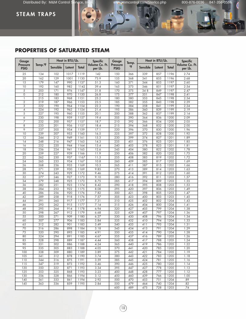
PROPERTIES OF SATURATED STEAM
GaugePressure
PSIGTemp.ºF
Heat in BTU/Lb. SpecificVolume Cu. Ft.
per Lb.
GaugePressure
PSIG
Temp.ºF
Heat in BTU/Lb. SpecificVolume Cu. Ft.
per Lb.Sensible Latent Total Sensible Latent Total
25 134 102 1017 1119 142 150 366 339 857 1196 2.7420 162 129 1001 1130 73.9 155 368 341 855 1196 2.6815 179 147 990 1137 51.3 160 371 344 853 1197 2.6010 192 160 982 1142 39.4 165 373 346 851 1197 2.545 203 171 976 1147 31.8 170 375 34 8 849 1197 2.470 212 180 970 1150 26.8 175 377 351 847 1198 2.411 215 183 968 1151 25.2 180 380 353 845 1198 2.342 219 187 966 1153 23.5 185 382 355 843 1198 2.293 222 190 964 1154 22.3 190 384 358 841 1199 2.244 224 192 962 1154 21.4 195 386 360 839 1199 2.195 227 195 960 1155 20.1 200 388 362 837 1199 2.146 230 198 959 1157 19.4 205 390 364 836 1200 2.097 232 200 957 1157 18.7 210 392 366 834 1200 2.058 233 201 956 1157 18.4 215 394 368 832 1200 2.009 237 205 954 1159 17.1 220 396 370 830 1200 1.9610 239 207 953 1160 16.5 225 397 372 828 1200 1.9212 244 212 949 1161 15.3 230 399 374 827 1201 1.8914 248 216 947 1163 14.3 235 401 376 825 1201 1.8516 252 220 944 1164 13.4 240 403 378 823 1201 1.8118 256 224 941 1165 12.6 245 404 380 822 1202 1.7820 259 227 939 1166 11.9 250 406 382 820 1202 1.7522 262 230 937 1167 11.3 255 408 383 819 1202 1.7224 265 233 934 1167 10.8 260 409 385 817 1202 1.6926 268 236 933 1169 10.3 265 411 387 815 1202 1.6628 271 239 930 1169 9.85 270 413 389 814 1203 1.6330 274 243 929 1172 9.46 275 414 391 812 1203 1.6032 277 246 927 1173 9.10 280 416 392 811 1203 1.5734 279 248 925 1173 8.75 285 417 394 809 1203 1.5536 282 251 923 1174 8.42 290 418 395 808 1203 1.5338 284 253 922 1175 8.08 295 420 397 806 1203 1.4940 286 256 920 1176 7.82 300 421 398 805 1203 1.4742 289 258 918 1176 7.57 305 423 400 803 1203 1.4544 291 260 917 1177 7.31 310 425 402 802 1204 1.4346 293 262 915 1177 7.14 315 426 404 800 1204 1.4148 295 264 914 1178 6.94 320 427 405 799 1204 1.3850 298 267 912 1179 6.68 325 429 407 797 1204 1.3655 300 271 909 1180 6.27 330 430 408 796 1204 1.3460 307 277 906 1183 5.84 335 432 410 794 1204 1.3365 312 282 901 1183 5.49 340 433 411 793 1204 1.3170 316 286 898 1184 5.18 345 434 413 791 1204 1.2975 320 290 895 1185 4.91 350 435 414 790 1204 1.2880 324 294 891 1185 4.67 355 437 416 789 1205 1.2685 328 298 889 1187 4.44 360 438 417 788 1205 1.2490 331 302 886 1188 4.24 365 440 419 786 1205 1.2295 335 305 883 1188 4.05 370 441 420 785 1205 1.20100 338 309 880 1189 3.89 375 442 421 784 1205 1.19105 341 312 878 1190 3.74 380 443 422 783 1205 1.18110 344 316 875 1191 3.59 385 445 424 781 1205 1.16115 347 319 873 1192 3.46 390 446 425 780 1205 1.14120 350 322 871 1193 3.34 395 447 427 778 1205 1.13125 353 325 868 1193 3.23 400 448 428 777 1205 1.12130 356 328 866 1194 3.12 450 460 439 766 1205 1.00140 361 333 861 1194 2.92 500 470 453 751 1204 .89145 363 336 859 1195 2.84 550 479 464 740 1204 .82
600 489 475 728 1203 .74
Distributed By: M&M Control Service, Inc. www.mmcontrol.com/Sterlco.php 800-876-0036 847-356-0566
19
STEAM TRAPS
NOTES:
Distributed By: M&M Control Service, Inc. www.mmcontrol.com/Sterlco.php 800-876-0036 847-356-0566
In 1916, the company, then known as
the Sterling Engineering Company,
began designing and manufacturing
valves, traps, strainers and
condensate pumps for steam and hot
water systems.
Today, with more than 90 years of
application experience, a diverse
engineering staff, state-of-the art
CAD design and thousands of
custom applications, we
are uniquely suited to
meet your individual
requirements and
specifications.
STERLCO® PRODUCTS INCLUDE: • HAND RADIATOR VALVES • THERMOSTATIC TRAPS • FLOAT AND THERMOSTATIC TRAPS • INVERTED BUCKET TRAPS • CAST IRON STRAINERS • BRASS STRAINERS • BOILER FEED UNITS• TANK AND PROCESS TEMPERATURE CONTROL VALVES • CONDENSATE PUMPS
Distributed By: M&M Control Service, Inc. www.mmcontrol.com/Sterlco.php 800-876-0036 847-356-0566