Embed Size (px)
Citation preview
Steel Building Apartment- Design
and Build Sutton Yanosky
ET494 – Cris Koutsougeras

Birds Eye View

New Structures
• As an addition to the high efficiency home build from last semester, the owner has proceeded into the phases of adding 2 additional structures onto their property.
• A steel warehouse, housing 2 full multi-room apartments
• A pool side cabana structure with full kitchen and bathroom.
• Both structures require ground up construction from pre-design phase until project completion.
• This requires working CAD drawings and specifications for each of the structures, a construction schedule, cost estimates, materials lists, necessary structural calculations, etc.

Steel Building Shell Examples

Steel Building with Apartments
• The size of this steel structure will be 60’ X 100’.
• The 2 apartments to be added will be single story housing at least one bedroom, full bathroom full kitchen and dining area and will also be used for storage overhead.
• All bearing walls for both will be framed using 16 gauge steel studs and joists.
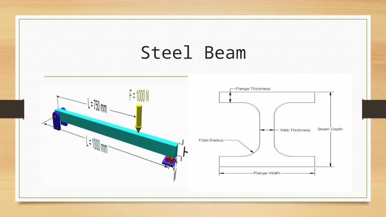
• The picture shows typical cross-section of some of the steel members that will be used.
Steel Warehouse and Apartments
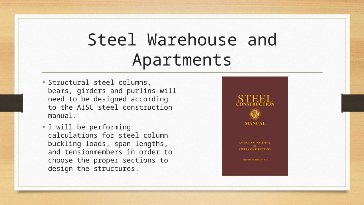
• Structural steel columns, beams, girders and purlins will need to be designed according to the AISC steel construction manual.
• I will be performing calculations for steel column buckling loads, span lengths, and tensionmembers in order to choose the proper sections to design the structures.

LRFD Load Resistance Factor Design
• D = dead load due to the weight of the structural elements and other permanent features supported by the structure, such as permanent partitions.
• L = live load due to occupancy and movable equipment
• Lr = live roof load
• W = wind load
• S = snow load
• E = earthquake load
• R = initial rainwater load or ice water load exclusive of the ponding contribution

LRFD Load Formulas
• 1.4(D + F)
• 1.2(D + F) + 1.6(L + H) + 0.5(Lr or S or R)
• 1.2D + 1.6(Lr or S or R) + (L or 0.8W)
• 1.2D + 1.6W + L + 0.5(Lr or S or R)
• 1.2D + 1.0E + L + 0.2S
• 0.9D + 1.6W + 1.6 H
• 0.9D + 1.0E + 1.6 H
Use the largest positive and largest negative loads from these calculations for compression and tension of the member

Steel Beam Design
• Step 1 Identify all loads and design constraints (yield strength, maximum allowable deflection Δmax, beam length L, etc.).
• Step 2 Draw the load diagram and calculate all reactions.
• Step 3 Draw the shear and moment diagrams, and calculate Vmax and Mmax. If the loading conditions are right, use the Formula Method to find these values.
• Step 4 Calculate the plastic section modulus Zx required to support the applied moment. Select the lightest steel beam from the Appendix that supports Mmax and has enough stiffness to limit Δmax.
• Step 5 Include the beam weight in new drawings of the load, shear, and moment diagrams. Check that the beam can support the applied loads and its own weight, and that it still meets the maximum deflection constraint.
• Step 6 Calculate the shear strength of the selected beam, and check that the beam will support more shear load than is applied.
Steel Beam
Column Design
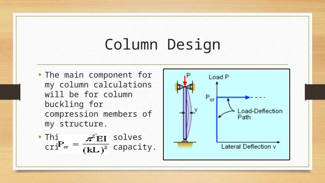
• The main component for my column calculations will be for column buckling for compression members of my structure.
• This equation solves critical load capacity.

Column Design
• K factor is constant based upon what kind or connection the columns uses.
• Buckling occurs when a straight column is subjected to axial compression suddenly undergoes bending.

Apartments and Cabana Structure
• This semester I will be producing full set of working for all three structures.
• All drawings for the builds will be made using AutoCad architectural software.
• Floor plan, foundation plan, electrical plan, joist/rafter plan, mechanical drawings, building elevations, connection details, foundation and wall details and room finish schedule will be completed for each structure.
• Once the drawing/design aspects are completed a material, labor and cost estimate will be formed along with a construction schedule and project network analysis.
• All estimates will be formed using Microsoft Excel.
• Scheduling will be done using Primavera software.
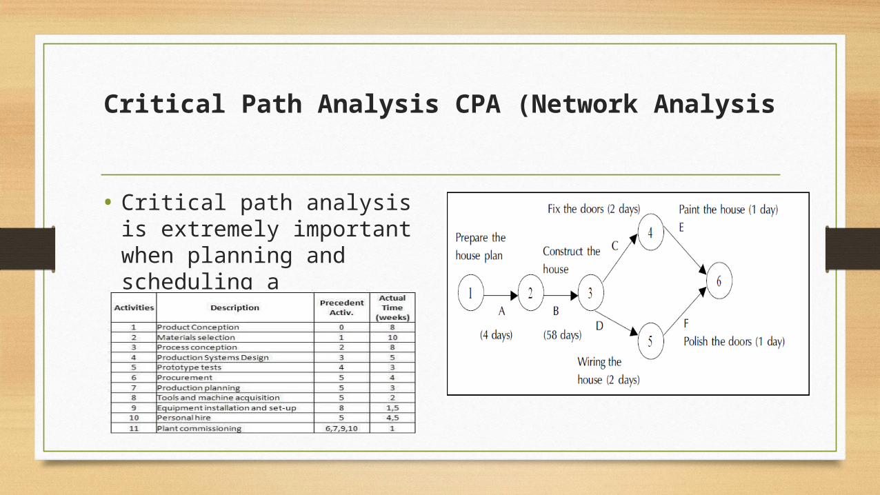
Critical Path Analysis CPA (Network Analysis
• Critical path analysis is extremely important when planning and scheduling a construction project.

Schedule and Critical Path
• This analysis will be done manually or utilizing Microsoft project and Primavera software.
• Project analysis includes:• Construction schedule
• Critical path
• Project duration
• Gant chart
• Project completion probability
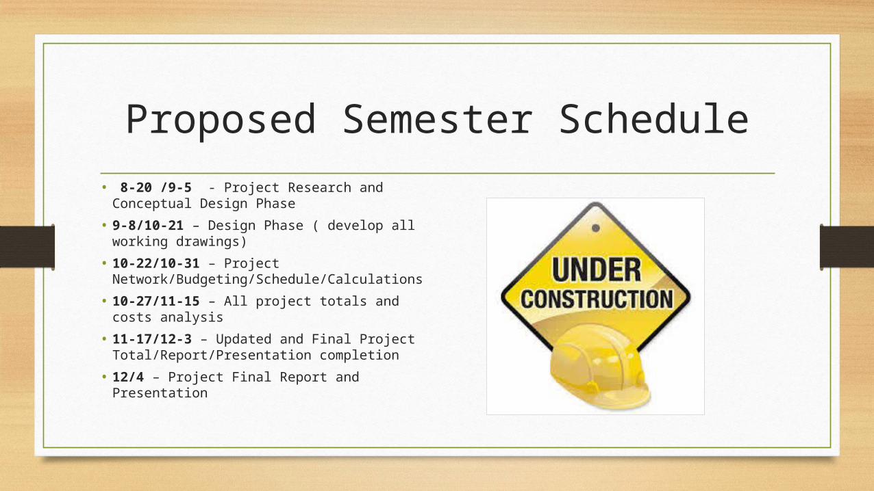
Proposed Semester Schedule
• 8-20 /9-5 - Project Research and Conceptual Design Phase
• 9-8/10-21 – Design Phase ( develop all working drawings)
• 10-22/10-31 – Project Network/Budgeting/Schedule/Calculations
• 10-27/11-15 – All project totals and costs analysis
• 11-17/12-3 – Updated and Final Project Total/Report/Presentation completion
• 12/4 – Project Final Report and Presentation
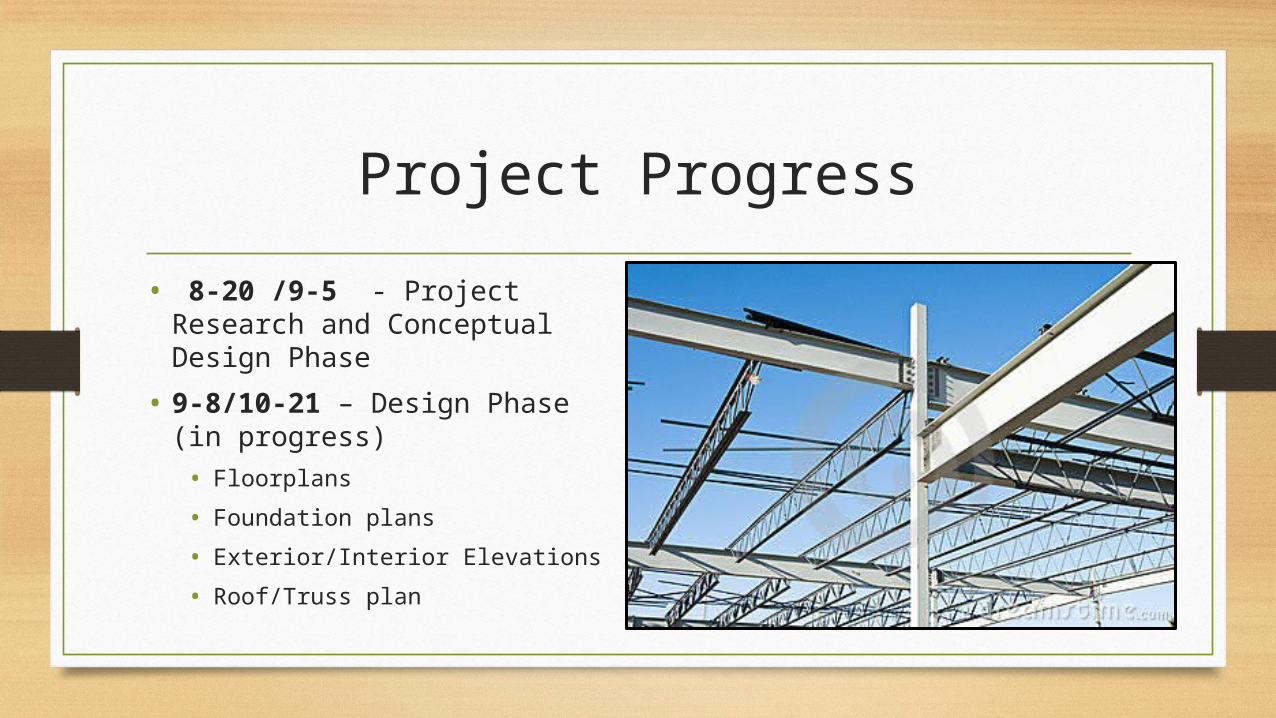
Project Progress
• 8-20 /9-5 - Project Research and Conceptual Design Phase
• 9-8/10-21 – Design Phase (in progress)• Floorplans
• Foundation plans
• Exterior/Interior Elevations
• Roof/Truss plan
Patrick Roach & Rob Arena

Questions?????