Embed Size (px)
Citation preview

STEEL FOUNDERS' SOCIETY OF AMERICA205 PARK AVENUE - BARRINGTON, IL 60010
Tel: 847-382-8240 - Fax: 847-382-8287 - www.sfsa.org
TECHNICAL FOLIO - TABLE OF CONTENTS Third Quarter, 2003
* TECHNICAL COMMENTARY
* T&O NEWS
* RESEARCH REPORTER
* SPECIFICATION NEWSASTM
ISO
*MISCELLANEOUSCalendar“CMC: Metalcasting Industry Technology Roadmap: Pathway for 2002 and Beyond”“Stainless Q&A”“Weldability of a Corrosion-Resistant Ni-Cr-Mo-Cu Alloy”

TECHNICAL COMMENTARY
STEEL FOUNDERS’ SOCIETY OF AMERICA
What is the greatest asset that a company has? How can a company stay at theforefront of its’ industry and continue to be a leader? There are various opinions aboutwhat makes a company a leader. The assets are usually listed as; good people, soundfinancial foundation, a growing market, a superior product, short lead times, high level ofon-time deliveries, ability to respond quickly to a customers needs.
How does a company maintain superiority?
Generally superiority is maintained by always being ahead of the competition. We seeall kinds of examples where markets are lost to competitors because we have notidentified the opportunities. This is more than making a product more technicallyacceptable it is more to do with timing. How do we measure how far we are ahead -well simply by assessing how long we think our competitor will take before catching up. If we make an improvement in a product and get it to market faster than our competitorsthen we are ahead. This is one of the problems we face now, we have not addressedthis issue in the past. We have not improved the product sufficiently we have tended tosupply to what has been a large domestic market. Our competitors have taken awaythe easy high volume product and cannot compete on the difficult product because theyhave not yet acquired the knowledge and expertise to produce these technicallydemanding products.
So the race is on, some of us know this others may not have realised it yet. How do westay ahead and how do we take back market share?
We stay ahead by investing in new ways to produce product, not simply becoming moreefficient which is of course important, but by becoming an irreplaceable part of thecustomers technical assets. How do we do this - one way is to “grasp the nettle” oftaking over the design of the castings our customers need. This whole question ofcarrying out the design work for our customers has always raised concerns over productliability. But, it is these kinds of changes in approach that increase the ability to stayahead of a competitor. Simply doing it faster, cheaper, better will not be sustainable inthe future. We have to break out of the box and become higher value suppliers.
3rd Quarter 2003

TECHNICAL & OPERATING NEWS
STEEL FOUNDERS’ SOCIETY OF AMERICA
National T&O Conference 11.06/08.03
By the time you read this the National T&O Conference will have taken place. It has been mostrewarding to see how many papers of such a high standard have been received. Attendance ismarginally down this year but that might be expected considering the appalling businessconditions most people have experienced over the last few years. Nevertheless, we areanticipating a great conference that has sustained it’s technical and operating value to themembership.
The conference will include the following awards:
The SFSA Foundation ScholarshipThis will be presented to Jeremy Baty, a Senior at Texas A&M with a major in IndustrialEngineering. Jeremy spent 14 weeks of this summer at Southwest Steel Castings studyingpattern storage and cleaning room issues. The requirements for the scholarship are that thestudent must make a presentation of his work at the T&O. Jeremy is the second student toreceive the scholarship which amounts to $5000. If you or your company want to find out howyou can become involved in this program you should contact Raymond Monroe at SFSA.
Shepherd Awards for the 2002 T&O ConferenceFirst time speaker award - Bob Bryant, Matrix Metals (Keokuk) for his paper on “Flat Sprue”. Bob will receive a check for $250 and a plaque marking his achievement.
First prize for best paper - This year we have joint winners - John Cory, Durametal Corporationfor his paper on “Electrostatic Powder Coating of Molds” and George Hartay, FALK Corporation“Saw Cutting Large Diameter Risers”. Each will receive a check for $500 and a plaque markinghis achievement.
Charles W. Briggs MedalHoward Thiemens of Spokane Steel will receive the Charles W. Briggs Medal. Howard hasbeen a great supporter of the SFSA activities not only by serving as the Western Division T&OChairman and the National T&O Chairman but also his role in the areas of regulatory activityand MACT make Howard a most deserving recipient.
All of these awards also reflect on the support that the companies have given to allow theiremployees to work and develop what is the fabric of SFSA. SFSA might not exist today withoutthis support that has developed one of the most effective steel casting associations in the world._____________________________________________________________________National T&O Committee G. Hartay, FALK Corp J. Cory, DurametalE. Granitz, North Star Steel S. Kulkarni, Matrix Metals J. Lilley, Wollaston AlloyH. Phillips, Southwest Steel R. Wabiszewski, Maynard Steel3rd Quarter 2003

RESEARCH REPORTER
STEEL FOUNDERS’ SOCIETY OF AMERICA
One of the problems with the research program is that we do not emphasise thebenefits that are likely to accrue from this work. To this end the following is a moreliteral presentation of the research work.
Determination of the effect of radiographic indications on performanceEffect of Niyama values on mechanical propertiesRadiographic stanadrds are workmanship standards, they do not indicate the effect on performance. Theneed in the steel casting industry is to produce highly efficient designs that can optimise the properties ofsteel. This work is designed to develop an understanding of the effect of indications on performance andthen develop a standard which can be used by designers to optimse casting design. This will lead tolighter and more competitive steel castings.
Heat treatment procedure qualificationA number of years ago the Materials Technology Institute examined aseries of stainless steel castingswhich had failed prematurely. The cause was predominantly attributed to inadequate heat treatment. Thishas experience has been confirmed not only in other grades of stainless steels but in carbon and low alloysteels where reheat treating to acheive propoerties is not uncommon. Th thrust of this program is toidentify how heat treatment can be best controlled to produce consistent product quality. It should not beassumed that ASTM or other specifications provide enough information to ensure consistency - they donot. This program will lead to reduction in heat treatment costs and customer returns.
Duplex stainless steel (DSS) weldingWelding of DSS is not well understood. The effect of heat treatment on the corrosion reistance afterwelding with matching and non-matching filler has not been studied. Field welds use overmatching fillermetals to ensure that the ferrite balance is maintained. In process welds with matching rods can be madeas long as they are followed by heat treatment. The common requirement from purchasers is now that allwelds must be post weld heat treated. However there has not been a study on the effect of heattreatment on corrosion performance. This work should lead to more consistent product quality andimproved performance in the field.
CCT diagrams for DSSThe heat treatment and limiting section sizes can best be indicated by exmining the CCT diagrams. Unfrtunately these do not exist for someof the most recently developed alloys. This work will assist thefoundry in perfoming effective heat ttreatments and identify where there may be problems in a castingdesign.
Pattern predictionOne of the biggest problem foundry engineers face is the prediction of the casting dimension. This projectis aimed at reducing the number of reverse engineering (“faking”) steps in casting production. Somesuccess has been achieved which may lead us to this goal. The effect of this work will be to reduceleadtime and their associated costs.
YieldThis work has successfully delivered a new set of rules for carbon and low alloy steels. The program isnow at the stage of developing rules for stainless steels and nickel base alloys. It appears that thestainless rules will be published shortly but the rules for nickel based grades will require some carefulinstrumentation of test castings. This project will lead to improved yield and reduced castingmanufacturing costs.

Burn-inA particularly stubborn defect to deal with causing excessive grinding time and sometimes scrap. Thiswork is aimed at revealing the variables that cause this problem. The intent is to develop practices whichwill eliminate or minimise this problem.
VariabilityThe biggest problem in the steel casting industry is variability of product quality. This project is a rangefinding study to assess steel casting quality variability. As large a problem as it is, most foundries do nothave a measure of variability and cannot assess its’ affect. Variability severely hampers the ability todetermine how much capacity is needed in the cleaning rooms this has a detrimental affect on deliveries. Software which is used in scheduling items through a series of operations cannot handle the variabilityseen in steel casting quality. The variability in steel foundries has been measured to be in excess of 80%.
Department of Energy RoadmapThe Department of Energy with input from the metal casting industry has developed a roadmap thatdefines the needs and technical barriers which must be overcome. A copy of this roadmap is available atthe SFSA website for review and downloading.
3rd Quarter 2003

SPECIFICATION NEWS
STEEL FOUNDERS’ SOCIETY OF AMERICA
ASTMA370 A SI (metric) version of this standard is being developed. It has been decided that theCharpy Impact testing section will be the first section to be revised.
A703 It is anticipated that the a ballot item to prohibiting the use of peening, plugging orimpregnating will be developed shortly.
A ballot item to reduce the amount of reporting on weld maps is to be prepared. The newguidelines will follow the CEN definition of weld sizes to be reported.
A923 The ballot item developed by SFSA for the inclusion of A890 4A (similar to wrought 2205)has passed all of the ASTM ballots. This now allows users to use the same screening test for bothcast and wrought forms of this alloy.
ASTM Proficiency test programs for the analysis of C&LA and stainless steels. If you areinterested in these programs you can obtain information at www.astm.org then go toProficiency/Cross Check Programs.ISOThree standards have now been approved;ISO 13583-2 Centrifugally cast high alloy materials - this standard includes alloys not currently in
ASTM,ISO 14737 Cast carbon and low alloy steels - this standard is similar to A958. ISO 4990 Steel castings - General technical delivery requirements is currently being balloted.
The following items are now being balloted;DIS 4991 Steel castings for pressure purposesDIS16468 General requirements for investment castingsDIS19959 Visual examination of investment castingsDIS19960 Alloys with special physical properties
Four new work items have been approved. These work items are aimed at harmonizing the ISOand CEN standards. As the CEN standards cover not only steels the ISO standards will beharmonized with the steel requirements only and not include irons and non-ferrous metals.;
ISO 4986 Magnetic particle inspection - Convenor DINISO 4987 Penetrant inspection - Convenor DINISO 4993 Radiography - Convenor ANSI(SFSA)ISO 11971 Surface inspection - Convenor ANSI(SFSA)
Two new work items have been developed ane are being balloted now. - these apply to theultrasonic testing of castings for general and highly stressed components. The intent here is toadopt the CEN stanadrds, which cover these items, without modifications.
3rd Quarter 2003

STEEL FOUNDERS’ SOCIETY OF AMERICAMEETINGS CALENDAR
2004
May18 Specifications Committee, Salt Lake City, UT
September 11/15 Annual Meeting - Ritz Carlton Hotel, Amelia Island, FL
November 3/6 National T&O Conference - Hotel Inter-Continental, Chicago, IL9 Specifications Committee, Washington, DC


CONTENTS Page
Introduction 1
A. Workshop�Overview 2B. Challenges 2C. Organization�of�this�Report 3
Current�Situation 5
A. Metalcasting�In�Brief 5B. Energy�Use�in�Metal�Casting 6C. Market�Overview 7
Improved�Metalcasting�Design�Capabilities 9
A. Material�Property�Data 9B. Design�-�Process�Interrelationship 12C. Design�Competitiveness 15
Improved�Metalcasting�Processes 21
A. Innovative�Processes 21B. Variability 24C. Intelligent�Processing 26D. Management�Issues�and�Systems�Approach 27
Crosscutting�Applications 31
Appendix�A:�Roadmap�Workshop�Attendees A-1
�


INTRODUCTION
This�Roadmap�outlines�technology�development�pathways�for�improving�energy-efficiency�andcompetitiveness�in�the�metalcasting�industry.��Specifically,�the�Metalcasting�Industry�Technology
Roadmap�outlines�the�technical�challenges�and�research�strategies�needed�to�achieve�the�goals�setforth�in�A�Vision�for�the�U.S.�Metalcasting�Industry�2002�and�Beyond�published�in�May�2002.��TheVision�presents�goals�and�challenges�identified�by�industry�leaders�that�must�be�addressed�over�thenext�20�years�to�maintain�a�healthy,�and�vibrant�metalcasting�industry.��Vision�goals�are�shown�inExhibit�1.
The�Cast�Metals�Coalition�(CMC)�developed�this�Roadmap�with�support�from�the�U.S.�Departmentof�Energy�(DOE).��The�CMC�represents�the�three�leading�technical�societies�of�the�U.S.�metalcastingindustry.��It�was�formed�to�foster�the�research�and�development�needed�to�help�the�industrybecome�technologically�advanced�and�globally�competitive.��The�member�societies�of�the�CMC�are:
� American�Foundry�Society�(AFS)
� North�American�Die�Casting�Association�(NADCA)
� Steel�Founders��Society�of�America�(SFSA)
To�remain�competitive�and�to�sustain�a�viable�domestic�metalcasting�industry,�significantchallenges�must�be�overcome.��Design,�process,�and�material�improvements�are�needed�for�theindustry�to�realize�its�potential.��Technological�advances�can�simultaneously�improve�productivity,energy�efficiency,�and�environmental�compatibility.��The�vast�majority�of�metalcasters�are�smallbusinesses�that�do�not�have�the�resources�to�perform�the�advanced�research�and�development(R&D)�necessary�to�remain�competitive.
The�CMC,�in�partnership�with�the�U.S.�Department�of�Energy�(DOE),�has�developed�a�successfuladvanced�research�partnership.��This�partnership�has�brought�together�industry,�academia,�andgovernment�to�implement�a�portfolio�of�research�projects�that�is�vital�for�improving�efficiency�inthe�industry�while�maintaining�competitiveness.�This�partnership�has�involved�hundreds�ofindustry�companies,�universities,�and�laboratories.��The�partnership�has�also�helped�to�trainhundreds�of�students.��A�significant�percentage�of�these�students�have�pursued�careers�in�themetalcasting�industry.��Significant�process�and�productivity�improvements�in�metalcasting�arehelping�improve�energy�efficiency.��The�partnerships�between�the�CMC�members�and�DOE�is�vitalto�this�small�business�manufacturing�industry�and�is�one�of�the�most�substantive�resources�forcasting-related�R&D�in�the�United�States.��This�Roadmap�provides�guidance�for�this�R&D�by�theU.S.�Department�of�Energy,�through�the�Cast�Metals�Coalition�and�its�members.
�
Exhibit� 1
Vision� Technical� Goals
� Through�improved�casting�design�methods,�alloy�properties,�alloy�performance�data,and�casting�performance�simulation�techniques,�annual�market�growth�rates�formetalcasting�shipments�(based�on�value�of�shipments)�will�average�3%�or�more�through2020.
� By�2020,�the�combination�of�average�melting�and�mold�yield�for�each�metalcastingalloy/process�family�will�increase�significantly�so�that,�in�aggregate,�the�metalcastingindustry�s�yields�will�increase�by�20%�from�current�levels.�Rejected�casting�rates�will�becut�by�40%�from�current�industry�averages.�On�time/complete�delivery�performance�forthe�full�spectrum�of�order/release�quantities�will�be�sustained�above�95%�across�themetalcasting�industry�while�the�combination�of�in-process�and�finished�inventory�inmetalcasting�plants�will�be�slashed�50%.

A. Workshop�Overview�and�Structure
In�January�2003,�the�CMC�hosted�a�technology�R&D�roadmap�workshop�to�outline�the�researchpathways�to�achieve�the�technical�goals�set�out�in�A�Vision�for�the�U.S.�Metalcasting�Industry�2002
and�Beyond.��Industry�leaders,�technology�specialists,�researchers,�and�government�participantscontributed�at�the�workshop.��The�workshop�was�organized�around�two�of�the�key�technicalchallenges�outlined�in�the�Vision:
� Design:�The�challenge�to�design�new�castings�for�new�markets�and�applications�while�maintaining
current�markets.
� Process:�The�challenge�to�improve�processes�for�reducing�scrap,�decreasing�production�costs,�and
improving�product�performance.
Workshop�participants,�who�are�experts�in�designing,�processing,�and�application�of�cast�products,participated�in�breakout�sessions�designed�to�map�R&D�pathways�for�overcoming�each�challenge.Participants�identified�the�existing�barriers�to�improving�design�or�manufacturing�processes.��Theyidentified�the�near-,�mid-,�and�long-term�research�activities�to�overcome�those�challenges.Participants�also�prioritized�the�research�efforts�needed�to�achieve�the�Vision�goals.��Insights�fromindustry�members�who�were�unable�to�attend�the�workshop�were�captured�through�a�pre-roadmapworkshop�questionnaire.��The�questionnaire�was�designed�to�elicit�input�on�how�to�best�achievethe�design�and�process�goals.��This�valuable�input�was�extensively�incorporated�into�thedevelopment�of�this�Roadmap.
B. Challenges
This�Roadmap�discusses�challenges�specific�to�the�breakout�session�topics:��design�improvementsand�process�improvements.��Interestingly,�similar�challenges�were�identified�in�the�breakoutsessions�and�in�a�plenary�session�involving�all�workshop�participants.��These�may�be�specific�toboth�design�or�process,�or�general�in�nature.��Yet�the�repeated�reference�to�these�challengesemphasizes�their�importance�to�the�industry.��Common�industry�challenges�include�the�need�to:
� Accelerate�the�rate�of�change�among�metalcasters.��To�accomplish�this,�the�industry�must
increase�training�and�technology�transfer�and�motivate�metalcasters�to�adopt�newadvances�and�technologies.
� Identify�and�prioritize�factors�that�reduce�variability�and�develop�measures�to�reduce�their
occurrences.
� Ensure�casting�quality�and�performance�at�the�design�stage.��Incorporate�and�improve
Advance�Quality�Planning�(AQP),�Design�Failure�Modes�Effect�&�Analysis�(DFMEA),�andProcess�Failure�Modes�Effect�&�Analysis�(PFMEA).
� Develop�measures�to�improve�process�control�in�casting�operations.
� Improve�the�efficiency�and�control�of�melting�processes,�which�includes�upstream�metal
preparation�and�downstream�molten�metal�handling.
� Develop�standards�for�quantitative�measurement�of�internal�and�external�casting�quality
attributes�based�on�objective�structural�performance�and�superficial�appearancerequirements.
� Develop�more�economical�processes�for�producing�castings�in�an�oxygen/contaminant-free
environment.
� Improve�automation�in�the�casting�process�and�reduce�the�number�of�process�steps.
� Improve�safety�performance�and�reduce�environmental�impact.
� Develop�new�pattern�materials�with�less�carbon�content�for�lost�foam�casting.
� Develop�the�capability�to�produce�mis-run-free,�thin-wall�castings.
�
Each�of�these�challenges�is�described�in�more�detail�in�Section�III��Design�Capabilities��(pg.�9)�andSection�IV��Processes��(pg.�21)�of�the�Roadmap.
C. Organization�of�this�Report
This�Roadmap�provides�an�overview�of�the�current�situation�of�the�metalcasting�industry�(SectionII)�and�the�results�of�the�roadmap�sessions�(Sections�III�and�IV).
Section�III�describes�the�various�obstacles/barriers�preventing�the�industry�from�obtaining�its�goalof�improved�metalcasting�design.��It�outlines�near-�(<�3�years),�mid-�(<�10�years),�and�long-term�(>10�years)�research�and�identifies�industry�research�priorities.��Research�needs�that�are�deemed�high-priority�are�italicized.��Section�IV�provides�a�similar�discussion�centered�on�the�goal�of�improvedmetalcasting�processes.��Section�V�describes�crosscutting�applications�that�these�research�areas�willhave�to�other�major�U.S.�industries.���Appendix�A�provides�a�list�of�attendees�of�each�breakoutgroup.
�


Current�Situation
Metalcasting�has�helped�the�United�States�become�the�world�benchmark�in�manufacturing,science,�medicine,�aerospace,�and�many�other�fields.��Metalcasting�is�a�vibrant�industry�of�small-to�medium-sized�businesses�that�helped�fuel�our�nation�s�prosperity�into�the�21st�century.Maintaining�a�strong�domestic�metalcasting�industry�is�vital�to�our�nation�s�economic�growth�andnational�security.
The�future�holds�great�potential�for�the�metalcasting�industry.��Research�advances�are�enabling�theindustry�to�produce�a�wider�array�of�castings�and�employ�a�broader�range�of�casting�processes�andalloys.��These�advances�result�in�higher-quality�castings,�enabling�castings�to�compete�effectively
with�other�methods�of�forming�engineered�components�for�existing�and�emerging�markets.
A. Metalcasting�in�Brief
Metalcasting�enables�the�production�of�both�simple�and�complex�parts�that�meet�wide-rangingneeds.��The�process�consists�of�introducing�molten�metal�into�a�mold�containing�a�cavity�of�thedesired�shape.��There�are�many�processes�used�to�cast�metal.��The�most�commonly�used�methodfor�small-�and�medium-sized�castings�is�green�sand�molding.��There�are�many�other�moldingprocesses�for�common�and�specialty�applications,�including�the�lost�foam�process�developed�inpart�through�the�DOE/CMC�partnership.��In�addition,�there�are�several�ceramic�moldingprocesses,�plaster�molding,�and�an�array�of�important�metal�mold�processes,�including�die�casting,squeeze�casting,�semi-solid�metalcasting,�investment�casting,�permanent�mold�casting,�chemicallybonded�sand,�and�centrifugal�casting.
Cast�metal�products�are�found�in�virtually�every�sector�of�our�economy.��Gray�and�ductile�ironscontinue�to�comprise�the�greatest�weight�of�casting�shipments,�followed�by�aluminum,�steel,copper,�and�zinc.��New�markets�are�opening�for�magnesium,�titanium,�and�other�nonferrous�alloysas�metalcasters�increase�their�ability�to�successfully�develop�new�markets.��As�illustrated�in�Exhibit2,�major�end-use�markets�include�transportation�(autos,�trucks,�railroad,�and�engines),
�
Exhibit�2
Metal�Casting�Supply�and�End-Use�Markets
�������������� ������������������������ �������������Current Industrial Reports������������ ��������������� �������� � ��!�����"���� ��"�Facts & Figures About the U.S. Foundry Industry�#����$$%%% �� ����&$������$� ��� ��� &����#��
�������������� ���
��������� �����������������
�������������������������� � �!��"����#�
������$"���"��������
%"���&��$� ����
'"����"!��
(�$ ���%�������)��
*"�� ���
��� �+��
,�"-�����./�
��������)��
��$$ �+�
0����� ������.�
1� �#�
2���)�#�
��� �)�.�

construction�and�mining�equipment,�pumps,�valves,�and�other�oilfield�and�petrochemicalequipment,�electronics,�agricultural�equipment,�military�weapon�systems,�and�myriad�othersmaller�niche�markets.
Markets�for�metalcasting�are�increasingly�more�competitive�and�customers�for�cast�metal�productsare�placing�more�emphasis�on�quality,�price,�and�delivery.��There�is�an�increasing�demand�forlighter-weight,�high-strength�ferrous�and�nonferrous�cast�metal�components�as�well�as�castingsthat�meet�demanding�service�requirements.
B. Energy�Use�in�Metalcasting
Metalcasting�is�an�energy-intensive�process;�in�fact,�it�is�one�of�the�nine�most�energy-intensiveindustries�in�the�United�States.��In�1998,�the�industry�(NAICS�3315)�spent�$1.2�billion�purchasingan�estimated�235�trillion�Btu.1��If�captive�foundries�areincluded,�the�estimated�energy�consumption�formetalcasting�processes�increases�to�328�trillion�Btu.2
About�59�percent�of�the�industry�s�energy�consumption�issupplied�by�natural�gas�and�27�percent�from�electricity.The�remainder�includes�other�fuel�sources�such�as�cokeand�breeze.3
As�illustrated�in�Exhibit�3,�approximately�55�percent�ofenergy�costs�are�in�melting,�while�moldmaking�andcoremaking�account�for�about�20�percent�combined.Heat�treatment�and�post-cast�operations�such�asmachining�also�use�significant�amounts�of�energy.4
Efforts�to�cost�effectively�reduce�melting�requirements�byincreasing�yield�and�reducing�scrap,�improving�meltingefficiency,�and�reducing�the�need�for�post�cast�operationswill�help�the�industry�to�save�energy�and�improveproductivity�and�competitiveness.
Total�industry�energy�costs�represent�10�percent�of�total�material�costs.��Iron�foundries�have�thehighest�energy�costs,�spending�about�$639�million�in�2000.��Throughout�the�metalcastingindustry,�energy�costs�represent�about�6�percent�of�the�total�value�of�shipments.��The�totalamount�of�energy�used�by�the�metalcasting�industry�is�comparable�to�the�total�amount�of�energyconsumed�by�residents�in�New�Hampshire,�New�Mexico,�Rhode�Island,�Wyoming,�and�Hawaiicombined.5
��������������� ������������������ ��� ����������� ���������������������� ������ ����� ���� !�"#��$������$�����%%�&����������'��())(����#�������' �����*�!������+���� � �����#��������+�������,$�����%%�&-� �����.�� ������������� ���� ��/�����#��#������! ��������������� ������ ���������.��� ��������+����� �/�����#���� ��������������� ������ ��� �$�����%%�&����� �������������������� ������ ����� �������������� ������������������ ��� ����������� ���!�"#���$��������������������� ������������������ ��� ����������� ������ �������������������� ������ ���!�"#�$��(�0'������� ��������� ��##�1�� ���2��$������ ���%%�&3�%%�&��3�%%�&(�3�%%�&(4����������������� ���������5������ ���������#�!��+� # ������������������.� �����#�1 ��#�� ��+���������#��������������������)����������������� ��� �������������������6������()))������#���.��� ���������������������������������������!�"#��(�����4������#�����������"��������7�()))�� �$������ ����%%�&����%%�&�(��%%�&(4��%%�&(&��%�&( �%%�&(�������%%�&((�
Exhibit�3
Process�Energy�Cost
��'�� ( �&��)*
+����� �� �&�,*
��'� �&�--* .� ��/�� ������0*
����� ( �&�1*
2�#����)*
*������� '�����&"�����
�������������� ��������������&"�����&"���� � ���"� ��3���% 4'������&"��2�� ������5������ '�/��#��'�& ������ '�� �� �&�5������"�����#��!�������Energy andEnvironmental Profile of the U.S. Metal Casting Industry��666���&���
�

C. Market�Overview
There�are�an�estimated�2,760�foundries�located�throughout�the�United�States�employing�210,000people.��A�majority�of�these�foundries�are�located�in�Ohio,�Indiana,�Wisconsin,�Alabama,�Michi-gan,�Pennsylvania,�and�Illinois.��These�seven�states�account�for�almost�75�percent�of�all�castingshipments�in�the�United�States.��Most�metalcasting�facilities�are�considered�small-�to�medium-sized�businesses.��Eighty�percent�of�these�facilities�employ�fewer�than�100�people,�only�14�percentemploy�over�100�people,�and�6�percent�employ�more�than�250�people.6
In�2001,�the�United�States�dropped�to�second�place�in�weight�of�world�ferrous�casting�production,with�16�percent�of�the�world�market.�China�leads�the�world�in�ferrous�casting�production,�with�24percent�of�the�world�market.��In�2000�and�2001,�China�experienced�a�10�percent�and�7�percentgrowth�in�ferrous�casting�shipments,�respectively,�while�the�United�States�experienced�nearly�a�10percent�decline�in�casting�shipments�in�2001.��Other�major�producers�of�ferrous�castings�areRussia,�Germany,�Japan,�and�India.�The�United�States�was�the�leader�in�nonferrous�castings�acrossnearly�all�alloy�types�with�24�percent�of�the�world�market�share,�down�from�27�percent�during2000.��Japan�followed�the�U.S.�with�12�percent�of�the�world�nonferrous�market.��Aluminumrepresented�90�percent�of�Japan�s�nonferrous�casting�shipments,�whereas�the�United�States�wasmore�diversified,�with�aluminum�accounting�for�68�percent�of�the�nonferrous�casting�shipments.Other�leading�producers�of�nonferrous�castings�include�Germany,�Russia,�Italy,�and�Mexico.�7
����������' ������ ������������8����0%&��������� ��8 #���������1 ���� ��9�())�:�Modern Casting�������"��())(�����(%
�


Improved�Metalcasting�Design�Capabilities
Research,�data,�and�tools�are�needed�to�improve�casting�design�methods.��This�includes�alloyproperties�and�performance�data�as�well�as�tools�to�accurately�simulate�casting�performance�basedon�stress�levels,�and�solidification�integrity.��These�improvements�can�reduce�component�weight,reduce�manufacturing�lead-times,�and�ensure�product�performance�to�increase�the�value�ofengineered�components�that�utilize�metalcastings.��New�design�tools�will�assist�manufacturers�inbuilding�better�products�with�less�cost�and�energy.��They�will�also�help�the�metalcasting�industrydevelop�new�markets�in�an�increasingly�competitive�global�market.8
In�developing�a�roadmap�to�achieve�that�goal,�industry�experts�identified�three�major�categories�ofchallenges�and�R&D:
� Material�Property�Data
� Design�-�Process�Interrelationship
� Design�Competitiveness
Research�needed�to�address�challenges�in�each�of�these�areas�are�outlined�below.��Pathways�toaddress�these�research�needs�are�illustrated�in�Exhibit�4�(pg.�18).�Research�needs�that�are�deemedhigh-priority�are�italicized
A.��Material�Property�Data
Designers�need�to�gain�better�access�to�property�data�on�material�characteristics�of�castcomponents�such�as�thermal�conductivity,�fatigue,�toughness,�stiffness,�and�creep�of�variousalloys.�These�material�properties�are�critical�in�the�design�phase�of�components.��Selecting�theproper�material�for�a�part�involves�more�than�selecting�a�material�with�the�attributes�necessary�fordesired�performance,�but�also�selecting�a�material�appropriate�for�the�optimum�casting�process.Properties�of�a�cast�alloy�can�change�based�on�the�molding�process�selected�by�the�designengineer.9
There�is�a�lack�of�material�property�data�on�cast�alloys�for�process�engineers�to�account�for�moltenalloy�castability�characteristics,�the�interface�heat�transfer�coefficient�with�various�moldingprocesses,�and�final�solidified�material�properties.��Development�of,�and�access�to,�this�data�wouldallow�process�engineers�to�meet,�with�confidence,�performance�requirements�through�processmodeling�during�the�preliminary�design�phase.��Material�property�data�on�cast�alloys�that�reflectthe�process�capability�to�meet�form,�fit,�and�function�would�greatly�enhance�the�selection�ofcasting�as�a�preferred�method�for�producing�engineering�components.
This�inaccessibility�of�material�properties�hinders�design�engineers�in�designing�castings�that�meetspecific�performance�criteria.��These�specifications�must�reflect�a�full�and�complete�analysis�of�thefunctions�required�of�the�casting.��Industry-wide�data�for�all�metal�alloys�should�include:
� Fatigue:��the�phenomenon�leading�to�a�fracture�under�repeated�fluctuating�stresses�having�a
maximum�value�less�than�the�ultimate�tensile�strength�of�the�material.10
Vision�Goal:��Through�improved�casting�design�methods,�geometry�performance,�alloyproperties,�alloy�performance�data,�and�casting�simulation�techniques,�annual�marketgrowth�rates�for�metalcasting�shipments�will�average�3�percent�or�more�through�2020.�
��������#��� �#�� ���A Vision for the U.S. Metalcasting Industry- 2002 and Beyond, ����������.����;�����Metals Handbook������������ ��#�������#��1�<��5=����� �����(4�����"��������(&

� Toughness:�the�ability�of�a�material�to�absorb�energy�and�deform�plastically�before�fracturing.In�metals,�toughness�is�usually�measured�by�the�energy�absorbed�in�a�notched�impact�test.11
� Stiffness:�the�ability�of�a�material�to�resist�elastic�deformation;�the�greater�the�stress�required�toproduce�a�given�strain,�the�stiffer�the�material�is�said�to�be.12
� Creep:��the�slow�deformation�process�that�limits�the�ability�to�sustain�loads�for�extendedperiods�of�time�at�elevated�temperature.��Thus,�the�geometry�of�the�part�changes�and�it�maylose�the�ability�to�perform�its�intended�function.��All�metal�alloys�creep,�but�some�have�higherresistance�to�creep�than�others.
� Patternmaker�s�Contraction�Factors:�average�patternmaker�s�contraction�varies�from�alloy�toalloy,�and�specific�values�depend�on�factors�yet�to�be�fully�defined.��Current�technologyrequires�tooling�builders�to�estimate�values�and�then�adjust�tooling�for�size�after�capabilitycastings�have�been�produced.
� Porosity:�pores�can�be�on�the�surface�of�the�casting�or�located�internally.��These�pores�arecaused�by�metal�shrinkage�and/or�gas�evolution�during�solidification.��Porosity�affects�theoverall�strength�of�the�casting.13��There�is�a�need�to�quantify�the�size,�position,�and�shape�ofporosity�and�simulate�its�effect�on�the�mechanical�and/or�physical�properties�for�alloys.
� Nonmetallic�Inclusions:��oxides,�usually�found�at�or�near�the�casting�surface.��As�withporosity,�the�size,�position,�and�shape�of�such�inclusions�need�to�be�quantified�and�their�effectson�mechanical�and/or�physical�properties�simulated.
Currently,�there�is�a�wide�availability�of�mechanical�property�data�on�wrought�metals.��Untildesign�engineers�have�access�to�a�similar�level�of�cast�alloy�property�data,�metalcastings�willcontinue�to�be�over-designed�and�under-utilized.�The�industry�s�objective�is�to�develop�the�designdata�needed�for�design�engineers�to�accurately�evaluate�metalcasting�as�a�viable�option�along�withforging�and�joining�mill�products.
Research�Approach
Near-Term�Research�Needs
To�address�material�property�data�challenges,�a�number�of�research�needs�were�identified�thatshould�be�performed�in�the�near�term�(0-3�years).��High-priority�research�is�identified�in�italics.These�include:
� Characterize�the�fatigue�behavior�of�cast�ferrous�and�nonferrous�alloys�with�parameters�used�in
design�software:�An�easy-to-apply�design�tool�is�needed�to�characterize�fatigue�behavior�of�castalloys.��Well-designed�castings�are�capable�of�resisting�high-cycle�fatigue,�but�tools�to�assist�indeveloping�fatigue-resistant�designs�are�not�available.��Most�successful�high-cycle,�fatigue-resistant�casting�designs�are�the�combination�of�a�design�engineer�s�personal�experience�andknowledge�of�allowable�stress�levels�in�critical�casting�sections.��Successful�designs�alsoincorporate�large�safety�factors�and�fatigue�life�testing.��It�is�common�for�designs�to�have�largerthan�necessary�fatigue�stress�safety�factors,�pass�the�fatigue�life�test,�and�then�not�revise�thedesigns�to�remove�unnecessary�mass.��Design�software�that�allows�designers�to��optimizedesigns��and�incorporate�fatigue�behavior�will�improve�casting�competitiveness.��Until�areasonable�database�of�cast�alloy�static�and�fatigue�properties�is�established,�a�simple�tool�isneeded�to�guide�design�engineers�in�the�early�stages�of�structural�casting�design.
�����.����;�����Metals Handbook������������ ��#�������#��1�<��5=����� �����&������"�������&&�����"�������>%��
�

The�opportunity�to�create�such�a�tool�may�lie�in�further�development�of�the�Modified
Goodman�Diagram.��Considerable�research�was�conducted�in�the�1960s�to�develop�ModifiedGoodman�Diagrams�for�cast�steels�and�compare�them�to�similar�wrought�steels.��The�ModifiedGoodman�Diagram�offers�important�features�useful�in�the�early�stages�of�structural�design.��Forexample,�its�graphical�format�provides�a�concise�means�to�convey�the�effect�of�casting�defectson�allowable�fatigue�stress,�and�it�couples�that�easily�to�the��R�ratio��of�minimum-to-maximumstress�in�cyclic�loading.��It�is�equally�useful�for�determining�allowable�tensile�and�torsionalshear�fatigue�stress.��Research�is�needed�to�establish�Modified�Goodman�Diagrams�foradditional�low-alloy�and�high-alloy�steels,�the�family�of�ductile�and�austempered�ductile�irons,aluminum�alloys�used�in�structural�applications,�as�well�as�magnesium�alloys,�for�which�littledata�exist.
A�portfolio�of�Modified�Goodman�Diagrams�will�help�in�early�stage�conceptual�design,preceding�the�development�of�final�solid�models,�Finite�Element�Analysis�(FEA),�fracturemechanics�analysis,�prototypes,�and�durability�testing.��The�benefit�of�addressing�this�researchwould�be�lighter�components�that�also�pass�required�life-cycle�testing.
� Wrought�equivalency�data:��Metalcasting�designers�need�the�same�level�of�mechanical�and
physical�property�data�for�cast�alloys�as�is�available�for�wrought�metals.�Developing�castproperties�data�is�much�more�complex�than�wrought�data�because�the�size,�type,�and�locationof�potential�solidification�discontinuities�must�be�considered.��However,�knowing�the�effect�onproperties�in�the�presence�of�discontinuities�enable�the�designer�to�use�the�design�freedom�ofcasting�geometry�to�optimize�a�casting.��Lack�of�metalcasting�properties�data�encouragescomponent�designers�to�default�to�fabrication�from�wrought�metals.��Access�to�cast�alloysproperties�data�provides�designers�with�information�to�reduce�the�weight�and�cost�of�castingcomponents�while�increasing�performance.
Mid-Term�Research�Needs
A�number�of�research�activities�necessary�over�the�mid�term�(4-9�years)�were�identified�to�improvethe�quality�and�understanding�of�material�property�data.��These�include�research�to:
� Determine�the�relationship�of�microstructure�to�casting�performance�characteristics:��Designengineers�need�to�understand�the�effects�of�microstructure�on�allowable�high-cycle�fatiguestress�in�metalcasting.��Metalcasting�processes�have�the�ability�to�increase�or�decreasesolidification�gradients,�resulting�in�finer�or�coarser�microstructures.��Designers�andmetalcasters�need�to�develop�an�understanding�of�the�effect�that�these�structures�have�onfatigue�properties.��R&D�in�this�area�may�include�the�Modified�Goodman�Diagram�data�on�themicrostructural�and�fracture�mechanics�data.��Due�to�the�complexity�of�this�research,�it�mustbegin�in�the�near�term,�continuing�to�the�mid�term.
� Develop�defect�threshold�data/standards:��Currently,�castings�with�microporosity,�inclusions�andother�solidification�features�may�be�labeled�defective�but�may,�in�fact,�function�properly.�Theindustry�must�determine�the�effect�of�size�and�distribution�of�specific�solidification�features�oncasting�properties�(including:�porosity�and�inclusions,�or�nonmetallic�particles�such�as�oxidesand�nitrides).��The�mere�presence�of�inclusions,�porosity,�or�other�imperfections�does�notnecessarily�mean�that�the�casting�will�not�meet�design�objectives.��Designers�need�property�dataand�acceptance�criteria�to�establish�a�solidification�feature�threshold�for�particular�cast�sections.
Using�Non-Destructive�Evaluation�(NDE),�a�solidification�feature�can�be�classified�by�its�size,shape,�type,�and�location,�allowing�the�investigator�to�determine�whether�or�not�the�indicationis�acceptable.��At�present,�NDE�standards�do�not�provide�any�insight�into�the�performancecapability�of�a�cast�part.�NDE�standards�need�to�be�developed�to�allow�designers�to�optimizecasting�design.
��

B.��Design�-�Process�Interrelationship
The�proper�combination�of�geometry,�alloy,�and�casting�processes�can�make��difficult-to-cast-alloys��economical�to�cast.��Designers�and�metalcasters�require�a�common�language�to�effectivelyapply�these�rules�in�design�for�manufacturing�(DFM).��Development�of�these�engineering�tools�andaddressing�these�interrelationships�will�lead�to�lightweight,�economical�casting�that�meet�allapplication�requirements.
Greater�understanding�of�governing�relationships�will�have�beneficial�crosscutting�effects�incasting�applications�as�well�as�in�quality�and�consistency�of�production.��There�is�a�need�todevelop�functional�prototypes�that�are�cost�effective�for�the�designer�and�are�representative�ofproduction�castings.��For�example,�capability�is�needed�to�prototype�permanent�mold�castings�thatare�faithful�to�production�dimensional�and�casting�integrity�requirements�before�an�expensivepermanent�mold�is�built.
Process-induced�conditions�often�result�in�significant�hand�labor�to�produce�a�casting�that�meetscustomer�requirements.��At�present,�not�all�dimensions�in�an�engineered�component�can�achievethe�required�dimensional�tolerance,�and�machine�finishing�of�castings�will�continue�to�berequired.��There�is�a�need�to�capture�the�effects�of�microstructure�features�and�residual�stress�onmachinability.��There�is�also�a�need�for�more�information�pertaining�to�parting�lines�and�variousprocess-induced�surface�conditions.
Another�challenge�is�that�cast�components�may�not�perfectly�conform�to�the�dimensions�of�thepattern�or�die�cavity�from�which�they�are�produced.��This�difference�occurs�because�of�processingvariables�and�variations�in�the�heat�transfer�at�the�mold/metal�interface�with�3-D�model�cavities.This�results�in�frequent�reverse�engineering�of�the�pattern�or�tooling�to�achieve�the�final,�desireddimensional�conformance,�which�is�costly�to�the�metal�caster.
Also,�many�designers�do�not�understand�the�casting�process.��This�includes�the�relationship�ofpattern�to�cores�and�the�draft�requirements�to�remove�a�casting�from�a�mold.��This�lack�ofunderstanding�can�at�times�lead�to�inappropriate�choices�relative�to�the�position�of�locators�on�acasting.��Thus,�dimensional�control�is�needlessly�sacrificed.��These�factors�could�be�resolvedthrough�proper�application�of�casting�design�rules.
Challenges�facing�the�design-process�interrelationship�fall�into�three�general�categories:
� Reduce�Variability�in�Dimensions�and�Solidification�Features� Understanding�the�Geometry/Alloy/Process�Relationship�to�Reduce�Variability�in�Material
Properties� Software�Models�and�Functional�Prototypes
The�following�briefly�describes�these�challenges.
� Reduce�Variability�in�Dimensions�and�Discontinuities:��As-cast�components�may�notperfectly�conform�to�the�dimensions�of�the�pattern�or�die�cavity�from�which�they�are�produced.This�difference�occurs�because�of�processing�variables�and�variations�in�the�heat�transfer�at�themold-metal�interface�in�complex�three-dimensional�mold�cavities.��This�results�in�costly�andtime-consuming�reverse�engineering�of�the�pattern�or�tooling�to�achieve�the�final,�desireddimensional�conformance.
Not�all�dimensions�in�an�engineered�component�can�achieve�the�required�dimensionaltolerance.��Machining�specific�features�will�continue�to�be�required.��There�is�a�need�to�capturethe�effects�of�microstructure�features�and�residual�stress�on�machinability.��There�is�also�a�needfor�more�information�pertaining�to�features�across�parting�lines�and�various�process-inducedskin�effects.
��

Metalcasting�dimensional�concerns�include�the�relationship�of�pattern�to�cores�and�the�draftrequirements�to�remove�a�casting�from�a�mold.��This�lack�of�understanding�can�lead�toinappropriate�choices�relative�to�the�position�of�locators�on�a�casting.��Thus,�dimensionalcontrol�is�needlessly�sacrificed.��These�factors�could�be�resolved�through�proper�application�ofcasting�design�rules.��Included�in�the�prudent�geometry�choice�is�consideration�of�the��processgeometry��(gating,�feeding,�solidification�shrinkage,�and�venting�of�gases).
Better�understanding�of�the�influence�of�alloys�on�the�specific�component�geometry�will�makereverse-engineer�the�dimensions�of�the�pattern�and�dies�economical�and�timely.��Designers�andmetalcasters�need�to�appreciate�how�the�alloy�will�behave�when�it�is�introduced�into�a�mold�ordie�cavity.��They�must�understand�how�grain�structure,�solidification,�and�properties�willinfluence�the�casting�geometry.
� Reduce�Variability�in�Material�Properties:��The�geometry-alloy-process�relationship�can�alsoaffect�properties�through�the�local�microstructure�and�the�generation�of�solidificationdiscontinuities.��These�can�adversely�affect�casting�machinability,�finishing,�mechanicalproperties,�and�tolerances.��For�example,�porosity�can�be�minimized�in�casting�designs�thatemphasize�progressive�solidification�toward�a�gate�or�riser,�tapered�walls,�and�avoidance�of�hotspots.14
There�is�a�need�to�develop�functional�prototypes�that�are�cost�effective�for�the�designer�and�arerepresentative�of�production�castings.��For�example,�capability�is�needed�to�prototypepermanent�mold�castings�that�are�faithful�to�production,�dimensional�tolerance,�and�castingintegrity�requirements�before�committing�to�expensive�production�tooling.
� Software�Models�and�Functional�Prototypes:�Design�engineers�and�metalcasters�challenged�tocost-effectively�develop�a�functional�prototypes�in�processes�other�than�sand�casting�(e.g.,�diecasting,�permanent�mold�casting,�lost�foam�casting,�and�investment�casting,�etc.).��Metalcastersconstruct�sand�patterns�to�test�designs.��Different�properties�are�achieved�in�engineering�alloysthat�are�cast�by�different�processes.��In�addition,�costly�trial-and-error�methods�are�required�toproduce�tooling�that�meet�dimensional�requirements.��The�physics�in�existing�software�modelstend�to�be�over-simplified,�making�it�difficult�for�metalcasting�engineers�to�accurately�predictthe�solidification�structure�in�engineering�alloys�with�complex�geometry.��More�robust�physicsis�needed�in�current�software�models�used�to�create�the�casting�practice.
Another�challenge�is�the�differences�between�the�properties�of�test�bars�versus�actualproduction�castings.��Test�bars�usually�have�a�uniform�section�thickness�and�simple�geometrywhereas�production�castings�have�a�complex�geometry�and�non-uniform�section�thickness.Tests�bars�are�engineered�conservatively,�are�virtually�free�from�shrinkage,�and�often�possesssuperior�mechanical�properties�compared�to�production�castings.��When�the�product�and�testbars�are�to�be�heat�treated,�a�test�bar�heat�treated�in�the�laboratory�may�receive�an�optimumheat�treatment�but�is�subject�to�more�variability�in�a�production�environment.��Finally,�thelocal�surface�finish�or�the�local�cooling�conditions�in�a�complex�geometry�casting�may�producea�different�microstructure�than�is�evaluated�in�a�separately�cast�test�bar.
Research�Approach
Near-Term�Research�Needs
The�metalcasting�research�community�and�industry�identified�research�that�should�be�performedover�the�near�term�(0-3�years)�to�improve�the�design-process�interrelationship.��High-priority
research�is�identified�in�italics.��These�research�activities�include:
�����.����;����������������� ������������ ��#�������#��1�<��5=����� �����>%��
��
� Refined�sand�model/improved�understanding�of�low-expansion�sand:�Metalcasters�and�designersneed�to�gain�a�better�understanding�of�low-expansion�sand�to�reduce�the�variability�of�castingdimensions�and�develop�a�sand�process�advisor�tool�to�determine�the�best�sands�and�geometriesfor�certain�sand�casting�components.�Designers�also�need�to�be�able�to�model�the�effect�ofvarious�sands�on�casting�quality.��Common�lake�and�silica�sands�have�high�rates�of�thermalexpansion�and�also�undergo�a�phase�change�at�high-casting�process�temperatures.��This�resultsin�dimensional�changes�in�the�casting�as�well�as�sand-related�surface�defects�on�the�casting.
� Quantify�the�effects�of�microstructure,�substructure,�and�residual�stress�on�machinability:
Quantifying�the�effects�of�microstructure,�and�residual�stress�on�machinability�would�enablemetalcasters�to�gain�a�better�understanding�of�these�characteristics�and�how�they�affect�themachinability�of�cast�components.
� Benchmark�sensitivity�of�process�variability�on�quality�and�identify�design�opportunities�to�reduce
variability.�(Near�to�Mid�Term):��Research�in�these�areas�will�assist�metalcasters�in�devisingdesign�strategies�to�better�control�process�factors�related�to�improved�product�consistency.
� Thermophysical�modeling�data�and�better�physics�for�design�models:�Thermophysical�datasuch�as�high-temperature�thermal�conductivity,�and�high-temperature�strength�are�needed�toimprove�the�accuracy�of�computational�models.��Currently,�most�process�models�do�not�adjustinput�parameters�to�account�for�experience.
� Use�of�pressure�during�solidification�(alloy�specific):��Internal�discontinuities�of�a�casting�can�beminimized�by�applying�pressure�to�the�casting�late�in�the�solidification�process,�therebyenhancing�certain�mechanical�properties.��Metalcasters�and�designers�need�to�gain�a�betterunderstanding�of�the�effect�of�these�internal�discontinuities�on�casting�mechanical�properties.
� Current�die�casting�design�models�need�to�be�upgraded�to�include��slurry-on-demand��for
Semi-Solid�Metals�(SSM):��Current�die�casting�design�programs�do�not�include�the�necessaryinputs�to�account�for��slurry-on-demand��for�SSM�die�casting�technologies.��There�is�a�need�toupgrade�current�die�casting�design�models�to�include�this�technology.
� Cooling�system�design�for�die�casting:��Computer�models�are�needed�to�accurately�designcooling�systems�for�dies.��Optimization�of�cooling�systems�for�dies�will�have�a�positiveinfluence�on�casting�quality�by�promoting�directional�solidification.��This�will�minimizesolidification-induced�porosity.
� Flashless�castings:�Flash�in�a�casting�is�a�fin�of�metal�that�results�from�separation�of�the�moldmating�surfaces.15��It�occurs�at�parting�lines�of�either�cores�or�patterns,�is�often�removedmanually�and,�therefore�is�a�labor-intensive�process.��There�is�a�need�to�determine�the�cast�partdesign�and�equipment/tooling�required�to�produce�castings�without�flash.��Designimprovements�are�necessary�to�enable�flashless�castings�and�minimize�labor�costs.
Mid-Term�Research�Needs
Research�activities�to�be�performed�over�the�mid�term�(4-9�years)�to�improve�the�casting�design-process�interrelationship�include:
� Develop�simulation�tools�to�predict�cast�component�properties:��Designers�and�metalcasters�have
a�need�to�develop�computer�simulation�techniques�that�will�predict�cast�component�propertiesbased�on�the�microstructure.��To�be�fully�functional,�computer�simulation�tools�need�toaccount�for�microstructure�and�solidification�features�that�could�affect�performance�of�a�castcomponent.
�����.����;�����Metals Handbook������������ ��#�������#��1�<��5=����� ������(?���

� Develop�rapid�tooling:�Conventionally�produced�tooling,�either�for�green�sand�molding�or�diecasting,�often�takes�months�to�produce�at�a�high�cost.�The�problem�is�that�sinking�this�cost�intotooling�early�in�the�design�stage�makes�it�difficult�to�implement�design�modifications.�The�longlead-time,�high�cost,�and�inability�to�modify�tooling�tends�to�discourage�designers�from�usingcastings.�Rapid�model�tooling�that�produces�functional�components�with�the�dimensional�andmechanical�characteristics�of�castings�produced�from�production�tooling�is�needed.��Newlydeveloped�rapid�tooling�models�must�be�flexible�and�allow�for�various�casting�processes�andtechniques�to�be�explored.��This�would�encourage�designers�to�utilize�castings�and�bring�newproducts�to�market�in�a�timely�manner.
� Optimize�compositional�elements�within�an�alloy�range:��Intelligent�systems�designed�to�operateon�the�shop�floor�must�be�developed�for�optimizing�compositional�elements�within�an�alloyrange.��This�would�ensure�proper�alloy�mixtures�and�help�ensure��as�designed��cast�propertiesand�performance.
� Solidification�modeling�of�dimensions:��Designers�and�metalcasters�need�to�develop�bettermodels�of�the�solidification�process�inside�a�mold�or�die.��These�models�should�take�intoaccount�shrinkage�attributes�of�various�alloys,�creep,�the�affect�of�casting�geometry�onsolidification,�and�other�factors.��This�will�assist�metalcasters�in�minimizing�and�preventing�theformation�of�any�discontinuities�that�can�arise�in�this�process.
� Change�Non-Destructive�Evaluation�(NDE)�standards:�NDE�standards,�especially�thoseproduced�for�X-ray�evaluations�are�very�subjective�and�need�to�be�updated.��Attempts�todigitize�existing�radiographs�have�not�been�satisfactory.��Researchers�need�to�develop�a�methodto�digitize�and�apply�these�standards�more�effectively.
� Application�of�Geometric�Dimensions�and�Tolerance�(GD&T):�GD&T�is�often�misunderstoodby�the�product�engineer�as�it�relates�to�castings�and�can�lead�to�application�problems�betweenmetalcasters�and�the�subsequent�machining�operation.��There�is�a�need�to�expand�GD&Tsystems�used�throughout�the�casting�design�phase.
Long-Term�Research�Needs
Research�identified�for�the�long�term�(10+�years)�includes�reliable�prediction�of�casting�performance
to�preclude�testing.��This�long-term�research�need�is�a�high-priority�for�the�metalcasting�industry.Metalcasters�need�to�develop�techniques�to�predict�casting�performance�before�the�casting�isproduced.��This�will�include�models�that�accurately�predict�the�size,�shape,�and�distribution�ofporosity,�shrinkage,�inclusions,�and�other�causes�of�variability.��These�model�descriptions�need�tobe�compatible�with�Finite�Element�Analysis�(FEA)�design�models�to�permit�concurrentengineering.
C.��Design�Competitiveness
Design�engineers�generally�lack�understanding�of�the�capabilities�and�properties�of�castings.Many�design�engineers�perceive�that�castings�are�not�the�optimal�choice�for�manufacturingcomponents�that�demand�high�quality�and�reliability�in�its�end�use.��Designers�tend�to�lackknowledge�of�the�positive�attributes�of�castings�and�the�unique�properties�of�cast�alloys.Therefore,�design�engineers�do�not�always�understand�the�requirements�of�the�metalcastingprocess.��Parts�that�could�be�more�economically�cast�are�forged,�machined,�or�molded�from�plastic.
The�metalcasting�industry�needs�to�anticipate�new�design�needs�instead�of�reacting�to�designingcastings�for�new�applications.��Limited�casting�process�knowledge�by�design�engineers�hinders�theindustry�s�ability�to�add�value�during�the�design�phase.��Inputs�into�the�design�phase�are�key�toreducing�costs�and�errors.��Metalcasters�need�to�become�full-service�providers�by�designing�the
��

casting�as�well�as�producing�it.��There�are�too�few�partnerships�between�metalcasters�and�theoriginal�equipment�manufacturers.��This�hinders�the�development�of�new�and�innovativeapplication�of�metalcasting�technologies�to�assure�the�mutual�benefit�of�the�original�equipmentmanufacturer�and�the�end�user.
Research�to�improve�design�competitiveness�will�assist�metalcasters�to�cut�costs�by�reducing�oreven�eliminating�costly�finishing�operations.��It�will�also�enable�metalcasters�to�expand�theircurrent�markets�by�producing�metalcasting�for�new�high-growth�industries.��This�growth�willoccur�through�the�education�of�design�engineers�in�proper�casting�techniques.��In�addition,development�of�tools�for�design�engineers�are�needed�so�casting�modules�with�geometric�rules�foreach�casting�process�are�embedded�in�computer�aided�design�software.��These�rules�assure�thedesign�for�manufacturing�principals�are�rooted�in�the�preliminary�design.
Research�Approach
Near-Term�Research�Needs
A�number�of�research�activities�were�identified�that�should�be�performed�over�the�near�term�(0-3years)�to�address�obstacles�to�improved�casting�design.��High-priority�research�is�identified�in�italics.These�include:
� Software�for�bi-directional�associativity�without�losing�geometry:��There�is�a�need�to�createa�software�package�that�will�allow�the�user�to�have�bi-directional�associativity�between�meshesand�solid�geometry.��The�current�software�for�Finite�Element�Analysis�(FEA)�takes�a�solid�model,overlays�a��mesh��of�finite�elements,�and�then�computes�stress/strain�across�the�faces�of�thefinite�elements.��However,�FEA�software�does�not�allow�the�user�to�change�the�stress/strainvalues�and�recompute�geometry.
� Materials/process�software�selection�program:��The�product�engineer�needs�a�softwarepackage�that�will�allow�easy�exploration�of�material�and�process�alternatives,�includingestimates�on�the�cost�to�manufacture�the�component.��Current�software�research�has�hadpromising�results.��This�research�must�be�widely�disseminated�to�industry.
� Design�for�downstream�manufacturing:��Design�capabilities�need�to�be�enhanced�to�reducepost-casting�operations.��For�example,�designers�can�enhance�fixtures�to�reduce�the�need�forintermediate�processes�such�as�machining,�assembly,�and�coating.
� Ongoing�training�on�how�to�integrate�the�use�of�various�tools:��Better�training�is�needed�forcurrent�and�future�designers�in�the�creation�and�use�of�solid�models.��Most�engineering�effortsare�spent�correcting�data�received�from�casting�customers.��Many�of�these�customers�still�useComputer�Aided�Design�(CAD)�stations�as�an�electronic�pencil.�There�is�a�need�forcompatibility�of�all�kinds�of�CAD�and�simulation�files�so�that�simulation�results�can�be�fed�backinto�the�models�and�design�changes�can�be�made�easily.
Mid-Term�Research�Needs
A�number�of�research�activities�were�identified�that�should�be�performed�over�the�mid�term�(4-9years)�to�address�obstacles�to�improve�casting�design.��These�include:
� Integrated�design�modeling�tool:��A�design�model�is�needed�to�show�the�relationship�betweenmaterial�properties,�the�specific�casting�process,�process�parameters,�and�the�influence�on�thefinal�cast�product.
��

� Develop�parametric�design�capabilities:�Designers�and�production�engineers�need�to�havenewly�developed�software�with�parametric�design�capabilities,�which�allow�them�to�change�oneparameter�and�cause�the�entire�model�to�adjust�accordingly.
� Model�and�volume-driven�tooling:�There�is�a�need�by�designers�and�production�engineers�todevelop�a�solid�model�that�integrates�the�design�and�expected�production�volumes�with�thetooling�construction�method�and�tooling�material�recommendations�made.��This�would�assistmetalcasters�in�avoiding�expensive�tooling�construction�and�materials�for�low-volume�designs.
� Rapid�tool�renovation/rework:�Modification�of�cast�component�tooling�to�meet�engineeringchange�orders�is�often�slow�and�costly.��This�is�a�significant�negative�for�the�design/productengineer�who�is�considering�a�casting�as�compared�to�a�machined�product.��Research�should�beperformed�to�develop�an�electronic�means�of�modifying�the�tooling�data�file�so�that�it�can�berapidly�transferred�to�the�toolmaker.��This�new�file�would�be�based�on�prototype�castings�andfeedback�from�electronically�digitized�parts.��It�would�automatically�reflect�conditions�based�onactual�prototype�casting�correcting�for�internal�and�surface�defects.
Long-Term�Research�Needs
Research�activities�were�identified�to�be�performed�over�the�long�term�(10+�years)�to�addresscommercial�obstacles�to�improved�casting�design.��Long-term�research�areas�were�designated�ashigh-priority�research�areas.�These�include:�new�technology�applications�(hydrogen,�electric,wind,�and�aerospace).��The�metalcasting�industry�needs�to�design�castings�for�new�technologyapplications�to�expand�markets�for�metalcasters.��Also,�an�integrated�casting�design�systemshould�be�developed�that�is�robust�enough�to�handle�process-and�application-specific�designconsiderations�
��

��
����������� ��������������������������������
������������������� ���� ���� ����
High-Priority�������+$�����@����������#���
�������� �������� ���������
������ ��������������
������������������� ����������������������������������������������� �������������������
���������� ����� ���������������������� ������������������������������������������������
������������������� ����������������������������������������������� �������������������
������������������������� ���������������������
���������������������� ���������
������������������������� ������������������� �����������
! ����������������������� �� ���������� �����������������������
���������������� �������������������������������������
������������������������������������������������������ �������������������������
Predict casting performancebefore the casting is produced
"������������������������������������������ �����
������������� �A���"�#��
������������� �A���"�#��
#�������������������������$�������������
��������� �������������������������������������������� ��� ������������������
%���������������������������������������������
�������������������������������������������������������
�������������� ����� ����������
����� ��� �������� ����� ������ ���������� ����
������������
������������������
����������� ����� ��������������� ��� ������������
� �/�����'���� ��#1 ����

�
������������������� ���� ���� ����
High-Priority�������+$�����@����������#���
�������� �������� ���������
����������������������
"�������������������������������������������������������
&����������������������������������������
������ ��� �������������������
��� ���������
'���������������������������
(���������������������������
� ��� ������ ���� ������� ���
!����� ����� ��� �"��� �#
'����������������������������
)������������������������


Improved�Metalcasting�Processes
In�its�Vision�for�2002�and�Beyond,�the�metalcasting�industry�recognized�the�importance�of�improvingmetalcasting�processes�through�increased�understanding,�accurate�simulation,�more�real-timecontrols,�and�improved�operating�efficiencies.��In�its�goal�for�2020,��the�combination�of�alloyimprovements�and�average�melting�yield�for�each�metalcasting�alloy/process�family�will�increasesignificantly.���In�aggregate,�the��metalcasting�industry�s�yields�will�increase�by�20�percent�fromcurrent�levels.��Rejected�casting�rates�will�be�cut�by�40�percent�from�current�industry�averages.��Ontime/complete�delivery�performance�for�the�full�spectrum�of�order/release�quantities�will�be�sustainedabove�95�percent�across�the�metalcasting�industry�while�the�combination�of�in-process�and�finishedinventory�in�metalcasting�plants�will�be�slashed�by�50�percent.�16
In�developing�a�roadmap�for�improving�metalcasting�processes,�the�industry�outlined�four�majorcategories�of�challenges�currently�keeping�the�industry�from�meeting�its�goals.��Industry�experts�thenidentified�research�needed�to�improve�metalcasting�processes.��This�section�outlines�challenges�andresearch�needs�identified�by�industry�experts�in�these�four�categories:
� Innovative�Processes� Variability� Intelligent�Processing� Management/Whole�Systems
Research�needs�that�are�deemed�high�priority�are�italicized.�The�pathways�to�addressing�these�researchneeds�are�illustrated�in�Exhibit�5�(pg.�29).
A. Innovative�Processes
The�metalcasting�industry�must�achieve�significant�improvements�in�world�marketcompetitiveness�as�well�as�energy-efficiency.��It�must�make�advances,�which�are�revolutionaryinnovations,�in�current�casting�and�melting�practices�and�technologies.
A�significant�improvement�in�yields�rates�with�reduced�energy�costs�without�major�capitalinvestments�are�sought.��For�example,�the�ability�to�control�shrinkage�during�solidificationwithout�risers�would�be�a�major�innovation�for�the�industry.�Similarly,�techniques�such�as�castingin�an�oxygen-free�environment�or�in-situ�pressurization�could�potentially�improve�casting�qualityand�improve�casting�yield.
Innovations�to�reduce�energy�and�melting�requirements�with�the�ability�to�recover�theinvestment�are�problematic.��Counter-gravity�pouring�can�have�significant�effects,�but�a�majorcapital�investment�is�needed�to�switch�from�a�gravity�pouring�system�to�a�counter-gravity�system.
����������#�� �#�� ���A Vision for the U.S. Metalcasting Industry – 2002 and Beyond����������
Vision�Goal:��By�2020,�the�combination�of�average�melting�and�mold�yield�for�each
metalcasting�alloy/process�family�will�increase�significantly�so�that,�in�aggregate,�the
metalcasting�industry�s�yields�will�increase�by�20�percent�from�current�levels.��Rejected�casting
rates�will�be�cut�by�40�percent�from�current�industry�averages.��On�time/complete�delivery
performance�for�the�full�spectrum�of�order/release�quantities�will�be�sustained�above�95�percent
across�the�metalcasting�industry�while�the�combination�of�in-process�and�finished�inventory�in
metalcasting�plants�will�be�slashed�50�percent.�
��

Research�Approach
Near-Term�Research�Needs
High-priority�needs�are�identified�in�italics.��A�number�of�high-priority�research�activities�can�beperformed�in�the�near�term�that�could�significantly�reduce�energy�use�while�improvingcompetitiveness.
� New�processes:�Existing�magnesium�and�other�nonferrous�casting�processes�do�not�fully�meetevolving�market�requirements.��Research�is�needed�to�develop�casting�processes�for�high-volume�nonferrous�castings�to�meet�future�market�demands�while�simultaneously�improvingefficiency�and�performance.��Achieving�these�goals�could�significantly�reduce�meltingrequirements�and�increase�industry�competitiveness.
� Lightweight�Materials:��The�contribution�in�energy�reduction�and�improved�energyefficiencies�can�be�significant�by�focusing�on�promoting�the�use�of�lightweight�materials.Magnesium�is�a�material�well�positioned�to�help�achieve�that�objective.��Magnesium�is�one-third�lighter�than�aluminum�and�two-thirds�lighter�than�ferrous�materials�with�excellentstructural�strength�properties.��Recent�market�conditions�have�made�magnesium�very�costcompetitive�with�aluminum�and�thus�set�the�stage�for�the�potential�of�rapid�growth�in�theautomotive�and�industrial�weight�reduction�applications.��In�addition�to�being�pricecompetitive,�magnesium�is�abundantly�available�globally�and�an�ideal�candidate�material�forcastings�to�achieve�weight�reduction�and�thus�significant�energy�efficiency�and�reduction.Research�is�needed�to�advance�the�use�and�applications�of�magnesium�in�casting�technology.
� Thin-wall�castings:��Casting�customers�increasingly�demand�components�that�are�lightweight.Continued�research�is�needed�to�develop�thin-wall,�high-strength�castings.��For�example,metalcasters�require�a�better�understanding�of�the�solidification�of�thin�section�castings�and�theevaluation�of�skin�effects.
� Energy-efficiency:��Research�can�determine�specific�measures�for�reducing�energy�use,�such�asdeveloping�refractories�that�do�not�need�to�be�cured�and�that�minimize�pre-heating�of�theladle.��The�effects�of�ladle�treatment/metallurgy�on�casting�yield�and�quality�should�also�beidentified.��In�the�near�term,�research�should�be�performed�on�wrought�steel�and�otherindustries�to�develop�lessons-learned�and�to�identify�proven�methods.
Mid-Term�Research�Needs
A�high-priority�over�the�mid�term�includes�developing�technologies�and�procedures�to�optimizemelting�practices�and�reduce�energy�consumption.��This�includes:
� Optimize�energy�use�and�melting�quality:�Methods�need�to�be�developed�to�optimize�energyuse�and�melt�quality�that�are�applicable�across�many�casting�methods�as�well�as�many�types�ofcast�components.��This�also�includes�methods�to�select�the�correct�type�and�size�furnace�forspecific�applications,�improving�melting�and�holding�technologies�and�practices�for�bothferrous�and�nonferrous�metalcastings,�and�systems�to�allow�the�industry�to�more�efficientlymelt�when�and�where�it�is�needed�thereby�reducing�holding�energy�requirements.
� Capture�thermo-electric�materials:��Utilizing�thermo-electric�materials�to�recover�waste�heatin�heat�treating�and�reintroduce�that�energy�into�other�process�heating�requirements.
� Optimize�the�size�of�the�flask:��Optimizing�the�size�of�the�flask�to�enable�pouring�at�a�lowertemperature.
��

� Schedule�and�production�techniques�to�eliminate�energy�intensive�processes:��Developingmore�efficient�scheduling�and�production�techniques�(i.e.�alloying�and�furnace�controls),�aswell�as�identifying�energy-intensive�processes�that�can�be�reduced�or�eliminated.
� Cupola�ore�to�coke�ration:�Reducing�the�variability�currently�present�in�the�use�of�the�cupolafurnace�and�identifying�techniques�to�increase�the�metal-coke�ratio.
A�number�of�other�measures�were�identified�that�if�performed�over�the�mid�term�could�lead�toimportant�innovations�in�casting�processes.��These�include:
� Real-time�control�of�melting�processes�including�dynamic�model-based�process�controls.
� Energy-efficient�melting�technologies�including�air-cooled�induction�melting�and�oxygen�andnatural�gas�injection�for�cupola�melting.
� Methods�for�real-time�management�of�metal�and�casting�quality�on�the�shop�floor.
� Improving�off-gas�analysis�and�systems�to�better�control�heats�and�to�help�ensure�the�propercombination�of�charge�materials���hot�metal,�scrap,�fluxes,�and�oxygen.
� Increasing�use�of�V-Process�(vacuum-process)�molding.
� Developing�materials�that�can�withstand�the�harsh�die�casting/molten�aluminum�environment.
� Developing�cost-effective�methods�for�die�casting�copper�alloys�and�steel.
� Developing�a�multi-acting�die�that�forces�near�net-shape�casting�without�risers.
� Developing/understanding�heat�pipe�technology�to�use�thermal�energy�more�efficiently�duringsolidification�in�die�casting.��There�could�also�be�applications�in�melting�furnaces�(water-cooledsections)�and�also�in�molds�where�chilling�is�of�paramount�importance.
� Developing�a�smart�die�to�identify�and�correct�problems�in�the�casting�before�they�occur.
� Improving�melting�technologies�for�aluminum�and�magnesium.
In�addition,�technologies�used�in�other�industries�need�to�be�investigated�to�determine�if�they�canbe�integrated�into�metalcasting�to�facilitate�leapfrog�advances�(i.e.�the�ability�to�produce�net-shapecastings).
Long-Term�Research�Needs
Over�the�long�term,�research�on�innovative�casting�processes�can�make�further�advances�leadingto�significant�improvements�in�energy-efficiency�and�competitiveness.�Some�examples�include:
� Lost�foam�pattern�materials:�A�high-priority�need�is�to�build�upon�the�successful�results�ofresearch�in�lost�foam�casting.��Foam�materials�with�lower�ash�content�are�needed.��The�successof�lost�foam�must�also�be�translated�to�steel�and�other�ferrous�casting.��Research�must�focus�onthe�production�of�pattern�materials�that�can�be�used�in�ferrous�casting�processes.
� Silica�sand�alternatives:�Crystallographic�R&D�should�be�performed�so�that�alternatives�tosilica�sand�can�continue�to�be�pursued.��This�can�produce�important�benefits�in�environmentalperformance,�energy�use,�and�industrial�hygiene.��Eventually,�the�industry�should�be�able�to
��

operate�foundries�without�silica�controls,�operating�in�closed-loop�systems�that�reuse�moldingmedia�rather�than�recycle�or�landfill�used�silica�sand.
� Alternative�to�traditional�coke:�Alternatives�to�traditional�coke�(i.e.�form�coke)�should�beinvestigated�to�identify�which�have�the�greatest�likelihood�for�success.��Research�should�beperformed�to�enable�broader�use�of�these�alternatives.
� Develop�magnetic�molds:�Other�long-term�research�activities�include�developing�magneticmolds�out�of�iron�shot.
� Develop�high-volume�castings�without�oxygen:��Develop�the�ability�to�produce�high-volume�castings�in�an�oxygen-free�environment.
B. Variability
Casting�variability,�along�with�the�difficulty�in�understanding�and�predicting�the�factors�thatcause�it,�results�in�unacceptable�scrap�levels�and�reduces�casting�yields.��Variability�also�slows�theproduction�process,�adversely�affects�scheduling,�increases�cleaning�room�inspection�and�otherpost-cast�requirements,�and�inflates�in-process�castings�and�inventories.
A�number�of�barriers�exist�to�reduce�variability�including:
� Poor�metal-delivery�systems�such�as�the�pouring�device,�runner,�and�gates.
� Difficulty�in�measuring�casting�variables�(hydrogen�levels,�mold�temperature,�and�moltenmetal�quality)�(e.g.�in�aluminum�casting)�in�order�to�control�them.
� Lack�of�engineering�tools�on�the�formation�of�inclusions�and�their�location�in�the�casting.
� Difficulty�controlling�composition�with�widely�varying�charge�material�attributes�that�cannotadequately�be�characterized.
� Difficulty�in�segregating�scrap�streams�from�different�alloys�may�cause�contamination.
� Inability�to�monitor�the�presence�of�trace�elements�found�in�scrap�that�is�introduced�into�thecharge.
� Lack�of�adequate�process�monitoring�throughout�the�process�from�molding,�melting,�pouring,and�post�solidification�processes.
The�industry�needs�to�quantify�the�effect�of�these�factors�on�yield�and�efficiency,�prioritize�them,and�implement�measures�to�reduce�or�eliminate�their�occurrences.
Common�practices�relating�casting�characteristics�to�service�requirements�do�not�exist.��Theindustry�needs�to�establish�standards�defining�casting�quality�acceptance�criteria�to�assure�castparts�meet�performance�goals.
Global�metalcasting�benchmarks�provide�self-policing�for�international�manufacturing.��Thesebenchmarks�may�include�yield�rates�(by�size�of�and�type�of�cast�product),�energy�conversionefficiency�(kWh�per�ton�of�casting�shipped),�and�refractory�efficiency�(kg�of�refractory�per�ton�ofcasting�shipped).��Global�metalcasting�benchmarks�also�presents�an�opportunity�for�moreefficient,�higher-quality�production.
��

Research�Approach
The�industry�must�understand�the�mechanisms�that�cause�solidification�discontinuities�in�order�tocontrol�their�occurrences.��High-priority�research�is�identified�in�italics.��A�high-priority�research�needin�the�near-term�is�to�determine�what�factors�affecting�variability�are�important�to�measure.�Theindustry�must�identify�the�critical�factors�for�controlling�product�and�process�variability;�establishtheir�roles�in�causing�solidification�discontinuities�to�quantify�their�impacts,�prioritize�thesefactors,�then�measure�and�control�them.
Similarly,�the�industry�needs�to�determine�which�causes�of�variability�can�be�measured�on�a�real-time�basis.��Implementation�of�such�measurement�devices�will�enable�the�industry�to�predict�theperformance�of�a�casting�and�reduce�inspection�requirements.��Documentation�of�best�practicesfor�reducing�variability�should�then�be�compelled�and�disseminated�to�the�industry�throughcontinuing�education.
Near-Term�Research�Needs
Specific�near-term�research�recommendations�to�help�reduce�variability�and�improve�metalcastingprocesses�include:
� Risers:�Improving�riser�designs,�or�eliminating�risers�altogether,�to�reduce�scrap�rates,processing�costs,�and�increase�yield.
� Thermal�management:�Improving�thermal�management�capabilities,�including�research�onmeasures�to�control�the�rate�of�heat�extraction�during�the�solidification�process.
� Optimize�heat�treating:��Optimizing�heat�treating�cycle�times/temperatures�and�improvingheat�treating�consistency.
� Standards�for�fluidity�tests:��Developing�standards�for�fluidity�tests�for�measuring�a�goodcasting.
� Methods�to�control�gases:��Developing�methods/technologies�to�control�gases�in�the�castingprocess.
� Identifying�and�eliminating�the�causes�of�poor�machinability.
� Developing�methods/technologies�to�reduce�or�eliminate�sludge�from�die�castings.
� Consistently�identifying�trace�elements�from�cross-feed�contamination�and�analyzing�theireffects�on�variability.
� Developing�the�ability�to�perform�real-time�X-ray�to�understand�the�mold�cavity�fillingsurface�area-to-volume�ratio.
� Analyzing�the�role�of�gravity�during�solidification.
� Performing�basic�studies�to�understand�element�partitioning�(i.e.�sulfur,�manganese,�andsilicon)�during�solidification�of�cast�irons�and�the�resulting�impact�on�mechanical�properties.This�could�enhance�designing�alloy�levels�to�meet�strength�requirements�for�a�specific�sectionsize.
� Developing�techniques�for�real-time�sand�control�to�reduce�sand-related�defects.
��

Mid-Term�Research�Needs
Over�the�mid�term,�research�can�be�performed�to�build�upon�near-term�activities�for�reducingvariability�and�to�significantly�advance�metalcasting�processes.��Specific�measures�recommendedby�industry�and�researchers�include:
� Smart�technologies:�Developing�smart�technologies�that�are�predictive�and�help�to�identifyand�reduce�or�prevent�the�occurrence�of�variability.
� Developing�the�capability�to�perform�semi-solid�processing�into�existing�dies���slurry-on-demand.
� Increasing�automation�in�the�cleaning�room�and�improving�cleaning�room�technologies�toreduce�in-process�castings.
� Developing�screening�tests�(e.g.�corrosion�tests)�to�certify�product�quality.
� Designing�castings�for�recyclability;�reducing�dross/slag;�and�understanding�the�impact�oftrace�elements.
� Improving�die�design�and�production�capabilities�to�reduce�post-cast�operations�such�assoldering�and�to�reduce/eliminate�trace�elements.
� Fully�characterizing�molding�media�properties�and�how�they�change�with�temperature.
� Developing�technologies�to�produce�ten�atmospheres�pressure�to�eliminate�porosity�incastings.
Long-Term�Research�Needs
Long-term�research�should�study�the�interrelationship�between�microstructure,�casting�process,and�product�performance.��This�research�should�help�to�improve�alloy�design�capabilities.��Alsoover�the�long�term,�a�high-priority�research�need�is�to�help�determine�material�selection�for�givenparts.��Contributing�research�will�include�analysis�that�increases�the�level�of�data�on�casting�alloyproperties�and�performance.���The�combination�of�both�research�activities�will�help�metalcastersto�better�determine�how�to�select�materials�that�meet�design�requirements�while�at�the�same�timereducing�cost�and�achieving�the�desired�weight�and�strength�of�the�casting.
C. Intelligent�Processing
A�better�understanding�of�mold�filling�will�enable�casters�to�significantly�improve�yield�and�scraprates�and�reduce�melting�requirements�with�a�robust�process�designed�to�ensure�quality.
Developing�a�greater�understanding�of�intelligent�processing�is�a�major�challenge�for�the�industry.The�harsh�environment�within�the�mold�requires�a�combination�of�advanced,�high-temperature(molten�metal)�sensors�that�can�withstand�this�environment.��These�measurements�are�needed�tovalidate�numerical�simulation�tools.��Sensors�are�also�needed�to�provide�fluid�flow�informationduring�mold�filling�and�heat�transfer�at�the�mold-metal�interface�during�solidification.��Theinformation�gained�can�be�used�to�develop�simulation-modeling�tools�that,�for�example,�canoptimize�gating�systems�to�reduce�scrap�rates�and�assure�consistent�quality.
��

Research�Approach
Near-Term�Research�Needs
Industry�and�researchers�identified�several�specific�needs�in�the�area�of�intelligent�processing�tohelp�improve�yield�and�scrap�rates�as�well�as�the�quality�of�cast�products.��In�the�near�term,simulation�and�modeling�tools�should�be�developed�to�better�predict�heat�treatment�anddistortion�so�that�metalcasters�can�implement�corrective�measures.��Thermophysical�data�as�afunction�of�temperature�must�be�developed�for�cast�alloy�compositions�to�be�used�in�simulations.Simulation�tools�must�be�validated�with�test�data�to�be�widely�accepted�in�the�industry.Metalcasters�need�real-time�evaluation�techniques�to�better�control�casting�quality�and�minimizethe�production�of�castings�with�unacceptable�discontinuities.�Utilization�of�these�process�controltechniques�will�minimize�the�scrap�level.
Mid-Term�Research�Needs
Intelligent�processing�systems�are�needed�to�improve�mold/die�surface�engineering.��These�toolsshould�help�to�optimize�die�surface�architecture�and�provide�data�to�support�predictive�modelingof�cast�quality�thereby�allowing�designers�and�metalcasters�to�make�necessary�adjustments�prior�tothe�actual�casting.
Over�the�mid�term,�durable�and�reliable�sensors�must�be�developed�to�perform�real-time�analysisand�data�gathering.��Specifically,�fluidity�tests�and/or�sensors�can�be�used�to�better�understandfluidity�and�solidification�as�well�as�to�read�cavity�fill�pressure.��A�better�understanding�of�theconditions�surrounding�cavity�fill�could�then�lead�to�a�reduction�or�elimination�of�secondary�trimoperations�and�other�scrap�reductions.��Also,�real-time�evaluation�tools�should�be�developed�tobetter�control�production.��For�example,�inexpensive�fluoroscopy�tools�are�needed�to�analyzecastings�in�real-time.�There�is�a�need�for�sensors�for�all�steps�from�molding,�melting,�pouring,shakeout,�and�post�solidification�processes�to�ensure�casting�consistency.
Long-Term�Research�Needs
Over�the�long�term,�intelligent�processing�systems�are�needed�to�better�understand�solidificationfundamentals�on�a�real-time�basis�and�to�help�control�the�solidification�process.��Simulation
tools�can�help�to�predict�and�avoid�casting�defects�such�as�hot�tears.��Research�also�is�needed�onthe�fundamental�properties�of�liquid�metals,�the��mushy�zone,��and�at�high�temperatures.Modeling�and�predictive�tools�can�be�developed�to�help�to�control�the��mushy�zone.�
D. Management�Issues�and�Systems�Approach
There�is�a�need�to�improve�dissemination�of�existing�and�emerging�technologies�to�management,engineers,�and�shop�floor�personnel.��This�understanding�is�key�so�action�can�be�taken�to�realizethe�potential�of�practices�or�methods�to�improve�process�control,�improve�production�efficiencies,reduce�energy�use,�and�reduce�costs.��Research�results�need�to�be�more�widely�disseminated�in�themetalcasting�industry�at�all�levels�so�new�technologies�can�be�adopted�and�implemented�morequickly.��Traditional�solutions�alone�will�not�produce�required�reductions�in�operating�costs,�norresult�in�significant�improvements�in�profitability.��A�paradigm�shift�is�needed.��The�industry�musttake�a�holistic�approach�and�consider�the�entire�manufacturing�environment�to�identify�potentialsolutions�for�improving�metalcasting�processes.��Lack�of�capital�is�a�major�barrier�inhibiting�thedevelopment�and�testing�of�new�management�practices�and�systems�as�well�as�industrialengineering�approaches.��However,�there�are�opportunities�to�learn�from�industries�on�how�to�linkperformance�and�compensation.��Training�and�education�delivery�systems�need�to�be�continuallyimproved.��Available�financial�resources�limits�the�ability�to�perform�research,�technologydissemination,�education,�and�training�needed�to�improve�metalcasting.
��

Research�Approach
Near-Term�Research�Needs
Specific�measures�that�could�improve�management�and�operating�systems�follow:
� Benchmarking�best�operating�procedures�for�metalcasting:�A�benchmark�study�should�beperformed�to�compare�U.S.�metalcasting�practices�to�those�being�implemented�in�Europe�andto�identify�any�advanced�practices�that�European�metalcasters�are�adopting.��It�is�alsoimportant�to�benchmark�the�metalcasting�industry�against�the�wrought�industry�to�identifycrosscutting�applications�that�may�apply�to�the�metalcasting�industry.��Industry�expertsidentified�this�as�a�high�priority�in�the�near�term.
Mid-Term�Research�Needs
� Centers�of�Excellence�as�testing�and�demonstration�facilities:�To�better�advancetechnology�development�and�dissemination�in�the�industry,�testing�and�demonstrationfacilities�should�be�established�in�several�locations�around�the�United�States.��These�should�becollaborative�efforts�that�build�bridges�between�industry,�universities,�and�government�fortesting�and�demonstrating�potential�leapfrog�technologies.��Individual�facilities�can�beestablished�for�specific�technology�or�focus�areas.��For�example,�one�facility�may�focus�onsensors�and�controls�while�another�may�focus�on�materials�analysis.�Industry�expertsidentified�this�as�a�high�priority�over�the�mid�term.
� Technology�transfer�and�training:�Technology�transfer�to�the�shop�floor�must�be�improved.Data�mining�is�needed�to�increase�technology�transfer�and�to�increase�the�existing�knowledgebase.��Plant�testimonials�and�success�stories�can�help�disseminate�technology�successes�andencourage�adoption�in�the�industry.��Also,�involving�metalcasters�in�new�technology�trialswill�help�to�disseminate�the�technology�more�quickly.��Many�small�foundries�and�die�castersare�not�able�to�conduct�extensive�training.��That�limits�improvements�in�metalcastingpractices�and�technologies.��Training�could�be�subsidized�by�trade�organizations�for�smallerbusiness,�including�training�on�state-of-the-art�process�control.��Lower-cost�or�limited�versionsof�new�software�could�be�provided�to�them.��These�are�high-priority�measures�identified�byindustry�that�must�be�implemented�on�an�ongoing�basis.
� Lead-time�reduction:�The�industry�must�continue�to�work�on�lead-time�reduction.��Newtechnologies�and�industrial�engineering�practices�that�can�contribute�to�lead-time�reductionshould�be�investigated.��Similarly,�advances�should�be�made�in�rapid�tooling,�rapidprototyping,�and�other�process�and�technology�methods�to�reduce�lead-time.
� Lean�manufacturing:�Operational�changes�including�lean�manufacturing�concepts�andvalue-stream�mapping�techniques�can�be�adapted�to�the�casting�processes.��Moreover,improvements�in�labor�productivity�tracking�(finishing,�tooling�changeover)�are�needed.Many�metalcasters�have�insufficient�information�concerning�the�cost�of�producing�a�casting,especially�the�small�metalcasters�producing�short-lots�of�castings.��Flexible,�automatedfinishing�equipment�is�needed�that�can�easily�accommodate�short�runs�of�different�castings.
� Environmental�management:�Innovative�methods�for�improving�solid�waste�managementshould�be�investigated,�tested,�and�deployed.��This�may�include�efficient�recycling�machiningchips�at�the�manufacturing�plant�or�opportunities�to�use�new�and�environmentally�friendlymachining�fluids�(e.g.�using�water�as�a�coolant�for�high-speed�machining�of�aluminum).
��
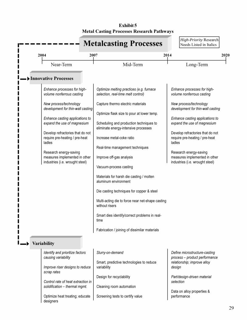
�
������������ ������������������������������������
����������� ������������ ���� ���� ����
High-Priority�������+$�����@����������#���
�������� �������� ���������
��������������������
*�������������������������� ���������� ��������
)��������������������������������������������������
*���������������������������� ������� ����������� �
����� ��������� ��������� �� ���$������� �������"���� ���������
!������������� ������������������������ �����������%&�&��� ���������'
%����������������������+����� ��������������,��������������������-
������������� ����������������
����(�����#�(��� �� ������� ��������&
���������������� ���� �������$���� �������������� ��������� ���
)������������ � #�����
!��� ��������������������$��
)��� ��� �� ��������
*����� �� ��������
��������� ����������������"�� ���������������� �����
��������������$���� ��� �����+�����
���� ���������� �� ������������ ������������� ������
���������������"� �������� ,���������� ���
��,���� ��"�- ���� ���������������
*�������������������������� ���������� ��������
)��������������������������������������������������
*���������������������������� ������� ����������� �
����� ��������� ��������� �� ���$������� �������"���� ���������
!������������� ������������������������ �����������%&�&��� ���������'
������ ���
'���������������������������� ���������������
'����������������������� ������������
������������������ ������������������������.������������
����(��������������.��������������
/� �������������
�����/��������������� � ���� �����������,���
������ ���������,���
��������� ����� ��� �
�������������� �������������
�������������� �� �����������������.���� �������������������������$������������������
(����������������������������������
����� ����� ���� ������+���� ������
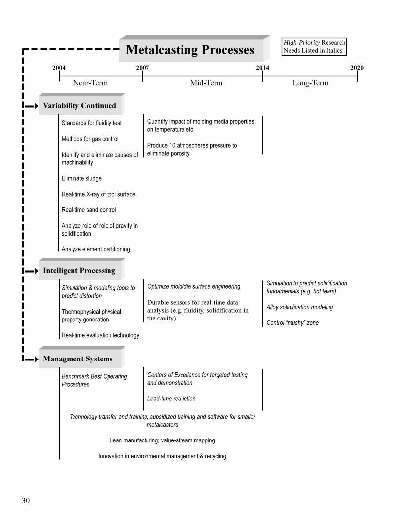
�
����������� ������������ ���� ���� ����
High-Priority�������+$�����@����������#���
�������� �������� ���������
������ ����������!�"
���������� ������������
���� ��� ������ ��� �
)������������������������ �������,���
�������������
!��� ����0 ���� ��� ��������
!��� ��������� ��� �
1����(��� ��� ��� ��� ���������� ������ �
1����(��������������� ���
2������������� ��� ������������ ����� �����������������&
3� �����45���� �������������� ��������� � ��
���� ����������������
/�� ������0��������������������������������
6���� ��������������� ������������� �
!��� ����������� ������� � ��
%��������������� ����������������
���"#������ ��� ���#B����������#�����,������#�������� #�������� ����+����.��-
/�� ������������������������������ ����������+������������-
1��������������������������
�������2� ���3���
���������#������
"��������"���%��������(����� ���
���������* ������������������������������������������
4����������� �����
#����������������������������$� ������������������������������������������������
7����������������.������ ������������
)�� ��� �������� �������������������+���������

Crosscutting�Applications
Research�to�address�the�obstacles�identified�in�the�area�of�casting�design�will�have�crosscuttingbenefits�to�other�industries.���For�example,�research�conducted�to�capture�microstructure�versusphysical/performance�characteristics�will�have�crosscutting�applications�that�apply�to�the�wroughtaluminum,�steel,�copper,�magnesium,�and�welding�industry.��Understanding�the�properties�ofcasting�alloys�will�assist�wrought�metal�producers�to�better�understand�their�own�product�sproperties,�thus�assisting�them�in�developing�better,�more�energy-efficient�products.
In�addition,�development�of�sensors�and�controls�for�casting�can�have�applications�in�othermanufacturing�industries.
Other�manufacturers,�such�as�the�forging�industry�and�powder�metal�industry,�will�benefit�from�anumber�of�the�rapid�tooling�design�programs�proposed�for�the�metalcasting�industry.��Thisresearch�will�also�help�to�expand�markets�for�metalcastings�while�at�the�same�time�producingmore�energy-efficient�technologies.
Research�will�help�designers�and�metalcasters�develop�lightweight�castings�for�the�transportationindustry,�assisting�U.S.�auto�manufacturers�to�develop�vehicles�with�higher�fuel�efficiency.��Themetalcasting�industry�will�also�be�able�to�develop�cast�components�that�will�assist�thepetrochemical�industry�and�power�generation�industry�in�developing�their�energy�systems�in�acost-cutting�energy-efficient�manner.��This�research�will�have�profound�effects�on�thedevelopment�of�a�hydrogen�economy�by�designing�lighter-weight�castings�that�will�make�thehydrogen�automobile�feasible.
��


Appendix�A
Roadmap�Workshop�Attendees
���


Design�Breakout�Group�Attendees
Name OrganizationCharles�Bates University�of�Alabama-BirminghamOmer�Diran Albany�Research�CenterRaymond�Donahue Mercury�MarineRobert�Eppich Eppich�TechnologiesMike�Gwyn Cast�Metals�CoalitionPaul�Kennedy Kennedy�Die�Casting,�Inc.Allen�Miller Ohio�State�UniversityRaymond�Monroe Steel�Founders��Society�of�AmericaMorgan�Mullikin USFilter/�CastalloyRobert�Naranjo BCS,�IncorporatedTom�Oakwood Professional�Metallurgical�ServicesVon�Richards University�of�Missouri-RollaPeter�Ried Ried�and�AssociatesMahi�Sahoo MTL/CANMETJoe�Santner American�Foundry�SocietyJerry�Thiel University�of�Northern�IowaNao�Tsmagari Briggs�and�StrattonSteve�Udvardy North�American�Die�Casting�AssociationJim�Van�Wert AMCAST�Industrial�CorporationJack�Wallace Case�Western�Reserve�UniversityWalt��Xianhua��Wan University�of�MichiganBeth�Waugh Cast�Metals�CoalitionHarvey�Wong U.S.�Department�of�Energy
Process�Breakout�Group�Attendees
Name OrganizationAl�Alagasamy Citation�CorporationDiran�Apelian Metal�Processing�Institute/�Worcester�Polytechnic�InstituteJohn�Berry Mississippi�State�UniversityMalcolm�Blair Steel�Founders��Society�of�AmericaNorman�Bliss American�Foundry�SocietyMike�Cox General�MotorsAlastair�Davidson Casting�Metallurgy�&�Process�Technology,�LLCKenneth�Green BCS,�IncorporatedGeorge�Goodrich Professional�Metallurgical�ServicesFrank�Goodwin International�Lead�Zinc�Research�OrganizationQingyou�Han Oak�Ridge�National�LaboratoryDarrell�Herling Pacific�Northwest�National�LaboratoryRick�Herreid Hormel�Foods�CorporationAl�Hetke Hetke�ConsultingJohn�Hryn Argonne�National�LaboratoryEhr-Ping�HuangFu U.S.�Department�of�EnergyFrank�Kemeny NUPRO�CorporationBill�LaFramboise Auburn�LaboratoryJohn�Monroe Colorado�School�of�MinesKen�Murphy ACIPCOTony�Overfelt NASA�Auburn�Solidification�Design�CenterKent�Peaslee University�of�Missouri-RollaFrank�Peters Iowa�State�UniversityJeet�Radia Keramida�Environmental,�Inc.Geary�Smith G�&�W�Electric�Co.Marty�Sorensen Idaho�National�Engineering�and�Environmental�LaboratoryDoru�Stefanescu University�of�Alabama
���


BY DAMIAN J. KOTECKI
Q:We aretryingto makefilletweldswithER209 in matching base metal (Nitronic50). We are experiencing severe crater cracking and some centerline cracking.We measuredferrite on the crackedweldsand found about 4 FN. I thought 3 to 4 FNwas sufficient to prevent hot cracking.W h y are these welds cracking,and whatcan we do about it?
A: A sample of the wire that was produc-ing the hot cracks was supplied to my lab-oratory. About 50 g of the wire was cut upto melt a button in a GTA furnace. Thebutton contained extensive crater crack-ing, as shown in Fig. 1.It should be appre- ciated that such a button solidifies com-pletely unrestrained, which should notpromote hot cracking., Measurement on the button beside thecracking revealed 4.1 FN. The wire man- ufacturer’s certification included all ele-ments necessary to calculate FN by meansof the WRC-1992 diagram, but a calcu- lated FN was not included. This was ob-tained by extrapolating the iso-ferrite lines of the WRC-1992 diagram to the calcu-
lated chromium equivalent of 23.3 and thecalculated nickel equivalent of 19.1. Thecomposition data, the measured FN, thecalculated FN, and the AWS A5.9 re-quirements for filler metal of the ER209classificationare included in Table 1.Con-sidering that extrapolation was used tocalculate FN, the calculated FN of 1.3 isin reasonable agreement with the meas-ured FN of 4.1.
Although 3 to 4 FN is normally suffi-cient to guarantee freedom from hot cracking, there are certain special cases in which it is not. These special cases in-clude very high-alloy stainless steel weldmetals, such as that of ER209. The WRC-1992diagram for stainless steel weld met-als includes a dashed line that separatescompositions that solidify as primary fer-rite (FA region on the diagram) from compositions that solidify as primaryaustenite (AFregion on the diagram). Pri- mary ferrite solidification is very resistantto hot cracking, while primary austenitesolidification is sensitive to hot cracking.This dashed line is not quite parallel tothe iso-ferrite lines of the WRC-1992 di-
Fig. I -GTA button melt of ER209. Notecrater cracking. The scale at left reads inmm.
agram. It is slightly skewed, so that leanalloys such as 16-8-2 can solidify as pri-mary ferrite even with less than 2 FN,while rich alloys such as ER209 solidify as primary austenite even with more than 5FN. Figure 2 shows this situation, includ-ing the ER209 composition supplied, onthe WRC-1992 diagram.
It’s risky to extrapolate both the iso-fer-rite lines and the dashed line between pri-
Table 1-Composition and Ferrite Number of ER209 Filler Metal
Element % C % Mn %Si %Cr %Ni %Mo %V %Cu %N
ER209AWSA5.9ER209
0.0430.05max
4.634.0to7.0
0.380.90max
21.0620.5
24.0
11.919.5to12.0
2.191.5to
3 . 0
0.140.10to
0.30
0.190.75max
0.280.10to
~ 0.30
Fig. 2-WRC-1992diagram with ER209 Sample plotted.
mary ferrite solidification and primaryaustenite solidification,but if that is done,
one would estimate that a calculated FN ofabout 8, minimum, would be necessary to
FNMeasured
4.1Not
Specified
WRC-19921.3Not
Specified
obtain primary ferrite solidification with the nickel equivalentof this filler metal.
Note: The inquirer subsequently ob- tained a new heat of ER209 filler metalwith calculated FN of 9, and no more hotcracking was observed.
DAMIAN J. KOTECKI is TechnicalDirector forStainless and High-Alloy Product Development for The Lincoln Electric Co., Cleveland, Ohio.He is a member of the A WS A5D Subcommitteeon Stainless Steel Filler Metals; AWS D1Structural Welling Committee, Subcommitteeon Stainless Steel Welding; arid a member andpast chair of the Welling Research CouncilSubcommittee on Welding Stainless Steels and Nickel Base Alloys. Questions may he sent to Mr.Kotecki c/o Welding Journal 550 NW LeJeuneRd., Miami, FL 33126 or via e-mail at

WELDING RESEARCH
WELDING JOURNAL
Weldability of a Corrosion-ResistantNi-Cr-Mo-CuAlloy
313 -S
Copper addition to a Ni-Cr-Mo alloy does not harmweldability, according to Varestraint test results
M. D. ROWE, P. CROOK, AND G. L. HOBACK
ABSTRACT Corrosion-resistant alloys alloys (Ref. 1).The modern corrosion-re-based on the Ni-Cr-Mo system are used in sistant Ni-Cr-Mo alloys have good resis-demanding applications in chemical tance to weld metal solidification crack-process, pollution control, and other in- ing. Weldability testing has been carried dustries. The ability to make sound welds out previously on Ni-Cr-Mo alloys with in these alloys with adequate corrosion re- additions of tungsten and titanium (Refs. sistance is critical for their use in most ap- 2,3), but the influence of copper on weld-plications. Varestraint weldability testing ability of the Ni-Cr-Mo alloyshas not beenwas carried out on a Ni-Cr-Mo-Cu alloy, explored in depth. Information on me-
(UNS N06200). chanical properties o f C-2000 alloy weld-Mechanical testing was conducted on ments and corrosion resistance of weldweldments. Immersion corrosion tests metal is not available in the published lit- were performed on all-weld-metal erature. The solidification cracking resis-coupons of C-2000 alloy in various envi- tance of B-38 alloy also has not been dis-ronments, including hydrochloric, hydro- cussed in the published literature. B-3fluoric, and sulfuric acids, with other Ni- alloy is a Ni-Mo alloy that was developedCr-Mo alloys included for comparison. to offer improved thermal stability in com- The resistance of C-2000 alloy to solidifi- parison to B-2 alloy, while maintaining thecation crackingwas similar to other Ni-Cr- same level o f corrosion resistance in suchMo alloys that are considered to be quite reducing media as hydrochloric acid. weldable, including and C-276. The Varestraint weldability test is usedAlloy C-2000 differs from other modern to measure the resistance of alloys to so-Ni-Cr-Mo alloys in that it contains l .6 lidification cracking. Solidification crack- wt-% copper. Copper does not have a ing occurs when partitioning of elementsdetrimental effect on the resistance of the during solidification causes low-melting-alloy to solidification cracking. C-2000 point films to form along solidification alloy weld metal met the minimum tensile grain boundaries. As the weld metal cools strength requirements of the base metal and shrinks, a level of strain may developand wasvery ductile, passing 2 T and 1.5T that exceeds the ductility of the partiallytransverse bend tests. The corrosion rate solidified material and causes separationof Alloy C-2000 weld metal was lower than of the grain boundaries along the liquidthat of the C-276 and C-22 alloys in hy- films. This type of cracking usually ap-drochloric, hydrofluoric, and dilute sulfu- pears along the weld centerline, especiallyric acids, similar to that of the C-22 alloy in thick or heavily restrained weldments,in ASTM G28A solution, and similar to and is present immediately after welding.that of C-276 alloy in ASTM G28B solu- The Varestraint test has been de-tion and concentrated sulfuric acid. scribed in detail elsewhere (Ref. 4). In the
test, a bending strain is applied to a sam-Introduction ple while an autogenous gas tungsten arc
weld is in progress. Cracking is induced inthe partially solidified metal at the trailingA Ni-Cr-Mo-Cu alloy, known commer-
cially as alloy(UNS N06200),was developed in the early1990s.The alloy was designed to maximizeresistance to uniform corrosion in both ox-idizingand reducing acids while maintain-ing a high level of resistance to pitting andstress corrosion cracking in chloride envi-ronments that is typical of the Ni-Cr-Mo
M. D. ROWE, P. CROOK and G. L. HOBACKare with Haynes International Inc., Kokomo, Ind.
KEY WORDS
Corrosion Resistance Nickel-Based Alloys
Varestraint TestSolidification Cracking
C-2000"
edge of the weld pool. The level of appliedstrain can be varied to tailor the severityo f the test to alloys that are more or less sus-ceptible to cracking.The amount of crack-ing is then quantified as the total crack length or maximum crack distance, allow-ing a ranking of materials with regard tocracking resistance. The minimum level ofaugmented strain necessary to producecracking is another indicator of crackingsusceptibility; a greater critical strain toproduce cracking indicates greater resis-tance to cracking.
Materials and Procedure
Varestraint Testing
The UNS numbers and trade names ofthe alloys are given in Table 1.The chem-ical compositions of alloys included in theVarestraint test matrix are given in Tables2 and 3. Two versions of the Varestrainttest were used: the full-scale and subscaleVarestraint tests. Varestraint welding pa-rameters are given in Table 4. A largerweld bead is produced in the full-scaletest, resulting in longer and more numer-ous cracks, which are easier to count andmeasure. The subscale test is more eco-nomical than the full-scale test, allowingfor a greater number of alloys to be tested and a greater number of replicate tests for improved statistical significance of results.Testing was performed in triplicate unless otherwise noted. After testing, the speci-mens were lightly buffed with a fine non-woven abrasive to remove any surfaceoxide, then the cracks were measuredunder a stereo zoom microscope equipped with a filar eyepiece. Cracklength was measured as the perpendiculardistance from the location of the solid-liquid interface at the time of loading.Both the total crack length (TCL) and themaximum crack distance (MCD) were re-ported. The MCD, along with the temper-ature gradient adjacent to the weld pool,can be taken as an indicator of the brittletemperature range (BTR) for a given alloy(Ref. 5). In the present investigation, it can be assumed that for a given set ofwelding parameters and similar material

WELDING RESEARCH
314 -S
Fig. 1-Full-scale Varestraint test results. Average total crack length vs. per-cent augmented strain.
NOVEMBER2003
Fig. 2-Full-scale Varestraint test results. Average maximum crack distancevs. percent augmented strain.
properties, the MCD gives an indication of the temperature range over which agiven alloy is susceptible to solidificationcracking.
Table 1-UNS Numbers and Trade Namesof Alloys
UNS No. Trade Name
N10276N06022N06200N06059
N06686N10665N10675N06625
C-276HASTELLOYHASTELLOY
5923 hMo
686
HASTELLOY625
(Alloy 59)
HASTELLOY B-2
(a) HASTELLOY, HAYNES, C-22, C-2000, and B-3 aretrademarks of Haynes International, Inc.(b) NICROFER is a trademark of Krupp-VDM GmbH.(c) INCONEL is a trademark of the Special Metals group ofcompanies.
Table 2-Chemical Composition of Alloys Evaluated with the Full-Scale Varestraint Test (wt-%)
AlloyHeat No.
CNbc oCrc uFeMnMoNiPSSiTiVW
C-2762760-9-3740
0.00270.250.97
15.850.106.450.49
15.5655.750.0080.00130.02
<0.010.173.52
c-222277-7-3179
0.0027<0.05
1.0321.520.054.730.24
13.4155.610.0070.00160.027
<0.010.133.03
c-20002316-9-8046
0.0041<0.05
0.1522.60
1.650.520.23
15.5758.30.0030.00260.034
<0.05<0.05
0.10
c-20002316-6-8006
0.00250.010.04
22.151.460.690.19
15.9459.070.0050.00180.01
<0.010.010.10
c-20002316-6-8007
0.0041<0.05<0.0522.92
1.510.740.23
16.5457.850.0050.0026
<0.020<0.05<0.05
0.12
Measurementof Elemental Partitioning in Weld Metal
One metallographic mount, in planview, was prepared from a representative full-scale test specimen of each alloy at thelocation of the solid-liquid interface at thetime of loading. Locations were identified on the etched surface where the cellularsolidification structure was running paral-lel to the surface of the sample. These lo-cations were marked with microhardnessindentations, then the sample was repol-ished. Both energy-dispersive (EDS) andwavelength-dispersive(WDS) X-ray spec-troscopy measurements were made in thescanning electron microscope to quantifythe partitioning of alloying elements.
A useful way to quantify the tendencyof a given alloying element to segregateduring solidification is with the equilib-rium partition coefficient (k ) .Microscopicsegregation in weld metal can be de-scribed using the Scheil equation, which
gives the composition of the first solid toform (at the dendrite core) as the nominalalloy composition multiplied by the parti-tion coefficient, k. If the value of k for a given alloying element is less than unity,the dendrite core will be depleted in thatelement, as is the case for molybdenum in nickel-based alloys.
It is possible to approximate k for agiven element in an alloy by dividing themeasured dendrite core composition bythe bulk alloy composition (Ref. 6). Fourrepresentative alloys were selected for EDS analysis of microsegregation. Addi-tional WDS measurements were made onAlloy C-2000. When calculating k , thebulk alloy composition was measured byan area scan of the weld metal for EDS,and several spot measurements in thewrought base metal for WDS. By using thesame technique to measure both the den-drite core and the nominal compositions for a given calculation of k, it was expectedthat the influence of systematic error in a
B-22665-9-6284
0.00310.10<0.10
0.820.051.670.82
27.8969.4<0.010
0.0030.04
<0.01<0.10
-
B-32675-9-6678
0.002<0.05<0.10
1.810.021.870.56
27.9966.33<0.004
0.003<0.02<0.01<0.01
0.93

WELDING RESEARCH
Fig. 3-Subscale Varestrainttest results.Average total crack length vs.percentaugmented strain.
Fig. 4-Subscale Varestrainttest results.Average maximum crack distance vs.percent augmented strain.
'lable 3-Chemical Composition of Alloys Evaluated with the Subscale Varestraint 'lest (wt-70)
AlloyHeat No.
CNbc oCrc uFeMnMoNiPSSiTiVW
C-2762 7 60-8-
3657
0.00310.051.53
15.550.075.990.50
15.4155.340.0070.00140.040.010.153.98
c-222277-8-
3159
0.00300.050.85
21.820.094.010.20
13.3256.470.0060.00350.030.010.182.84
c-20002316-4-
8000
0.00200.030.01
23.111.680.250.20
16.2357.79<0.004
0.00400.02
<0.01<0.01
0.06
c-20002316-9-
8024
0.00380.050.10
22.611.591.170.22
15.7457.550.0030.00300.020.050.050.05
c-20002316-6-
8005
0.00300.010.03
22.781.570.680.22
15.8958.000.0030.00600.01
10.01<0.01
0.09
5945241
0.0053<0.05<0.0522.580.030.550.17
15.9760.260.0030.00130.05
<0.050.13
<0.05
686
01BK
0.0042
NX19-
<0.05<0.0520.360.030.210.25
16.2059.150.0030.00150.0380.07
<0.053.94
B-2
6273
0.0030
2665-8-
<0.10<0.10
0.740.011.690.75
28.0365.94<0.004
0.00200.02
<0.01<0.01
-
B-32675-4-
6656
0.0020<0.01
0.021.430.011.480.64
27.8167.690.0040.00300.01
<0.010.010.04
625
6993
0.023.650.17
21.550.044.400.279.07
59.270.0060.0020.170.25
0.11
2650-6-
-
given measurement technique would beminimized. To give an estimate of the un-certainty in the analysis,k was calculated from at least five independent dendrite core measurements. The mean and 95%confidence limits were calculated from thefive replicate measurements of k. In thecalculation of k, no attempt was made tocorrect for solid-state diffusion duringcooling of the weld to room temperature.
MechanicalTesting
Plate weldments were prepared for mechanical testing using C-2000 alloy plate, 1 to 1.5 in. (2.5 to 38 mm) thick. Matching composition filler metal wasused. A single V-grooveweld preparationwith a 70-deg included angle and 0.12s-in.(3.2-mm) root opening was used for trans-verse tensile testing. All-weld-metal ten-sile and Charpy specimens were taken
Table 4-Varestraint Welding Parameters
Full Scale Subsc a 1e
Specimen dimensions, in. (mm)Current (A)Travel speed, in./min (mm/s)Arc length, in. (mm)Shielding gas, (L/s), argonTungsten electrode typeTungsten electrode diameter, in. (mm)Electrode included angle (degree)
2 x 12x 0.375(51 x 305 x 10)2204.5 (1.9)0.094 (2.4)35 (0.28)2% Thoriated0.125 (3.2)60
1x 6 x 0.125(25 x 152x 3)704.5 (1.9)0.037 (0.94)
2% Thoriated0.094 (2.4)60
35 (0.28)
from a 1-in.-thick plate using a 20-deg in- cluded angle, single-sided preparationwith a 0.7s-in. (19-mm) root opening and matching composition backing bar. Allwelding was performed manually in theflat position. Welding parameters aregiven in Table 5. All-weld-metal tensiletesting was performed according to Euro-
pean Standard EN 876.The specimenwasa round bar with a 0,394-in. (10-mm) -di-ameter by 1.97-in. (SO-mm) gauge length. Transverse tensile testing was performedaccording to European Standard EN 895.Specimens had a rectangular cross section measuring 1.00x 0.67 in. (25 x 17mm) and a 3.3s-in. (85-mm) gauge length. The av-
WELDING JOURNAL 315 -S
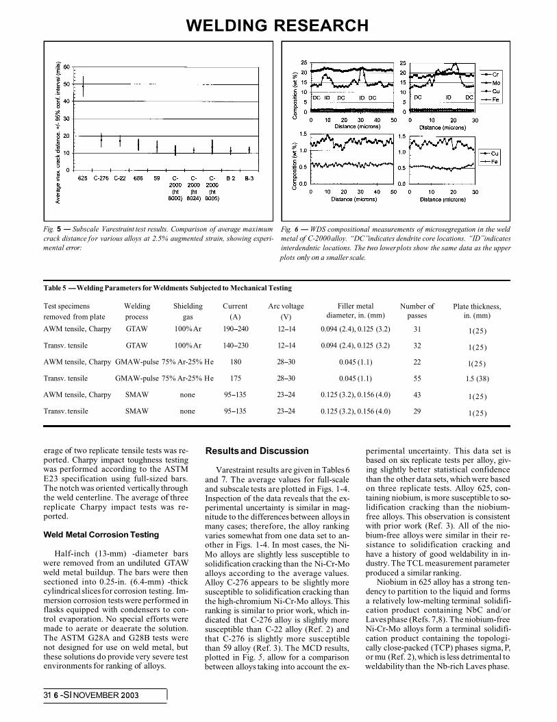
WELDING RESEARCH
Fig. 5-Subscale Varestraint test results. Comparison of average maximumcrack distance for various alloys at 2.5% augmented strain, showing experi-mental error:
Fig. 6-WDS compositional measurements of microsegregation in the weldmetal of C-2000alloy. “DC”indicates dendrite core locations. “ID”indicatesinterdendntic locations. The two lowerplots show the same data as the upperplots only on a smaller scale.
Table 5-Welding Parameters for Weldments Subjected to Mechanical Testing
Test specimens Welding Shielding Current
AWM tensile, Charpy GTAW 100%Ar 190-240
removed from plate process gas (A)
Transv. tensile GTAW 100%Ar 140-230
AWM tensile, Charpy GMAW-pulse 75% Ar-25% He 180
Transv. tensile GMAW-pulse 75% Ar-25% He 175
AWM tensile, Charpy SMAW none 95-135
Transv. tensile SMAW none 95-135
Arc voltage
(V)
12-14
12-14
28-30
28-30
23-24
23-24
Filler metaldiameter, in. (mm)
0.094 (2.4), 0.125 (3.2)
0.094 (2.4), 0.125 (3.2)
0.045 (1.1)
0.045 (1.1)
0.125 (3.2), 0.156 (4.0)
0.125 (3.2), 0.156 (4.0)
Number ofpasses
31
32
22
55
43
29
Plate thickness,in. (mm)
1(25)
1(25)
l(25)
1.5 (38)
1(25)
1(25)
Resultsand Discussionerage of two replicate tensile tests was re-ported. Charpy impact toughness testing was performed according to the ASTME23 specification using full-sized bars. The notch was oriented vertically through the weld centerline. The average of threereplicate Charpy impact tests was re-ported.
Weld Metal Corrosion Testing
Varestraint results are given in Tables 6and 7. The average values for full-scaleand subscale tests are plotted in Figs. 1-4.Inspection of the data reveals that the ex-perimental uncertainty is similar in mag-nitude to the differences between alloys inmany cases; therefore, the alloy rankingvaries somewhat from one data set to an-other in Figs. 1-4. In most cases, the Ni-Mo alloys are slightly less susceptible tosolidification cracking than the Ni-Cr-Moalloys according to the average values.Alloy C-276 appears to be slightly moresusceptible to solidification cracking thanthe high-chromium Ni-Cr-Mo alloys. Thisranking is similar to prior work, which in-dicated that C-276 alloy is slightly moresusceptible than C-22 alloy (Ref. 2) andthat C-276 is slightly more susceptiblethan 59 alloy (Ref. 3). The MCD results,plotted in Fig. 5, allow for a comparisonbetween alloys taking into account the ex-
Half-inch (13-mm) -diameter barswere removed from an undiluted GTAWweld metal buildup. The bars were then sectioned into 0.25-in. (6.4-mm) -thickcylindrical slices for corrosion testing. Im- mersion corrosion tests were performed inflasks equipped with condensers to con-trol evaporation. No special efforts weremade to aerate or deaerate the solution.The ASTM G28A and G28B tests werenot designed for use on weld metal, but these solutions do provide very severe test environments for ranking of alloys.
perimental uncertainty. This data set isbased on six replicate tests per alloy, giv-ing slightly better statistical confidence than the other data sets, which were based on three replicate tests. Alloy 625, con-taining niobium, is more susceptible to so-lidification cracking than the niobium-free alloys. This observation is consistentwith prior work (Ref. 3). All of the nio-bium-free alloys were similar in their re-sistance to solidification cracking andhave a history of good weldability in in-dustry. The TCL measurement parameter produced a similar ranking.
Niobium in 625 alloy has a strong ten-dency to partition to the liquid and formsa relatively low-melting terminal solidifi- cation product containing NbC and/orLavesphase (Refs. 7,8). The niobium-freeNi-Cr-Mo alloys form a terminal solidifi-cation product containing the topologi-cally close-packed (TCP) phases sigma, P,or mu (Ref. 2), which is less detrimental toweldability than the Nb-rich Laves phase.
31 6 -SINOVEMBER2003 I

WELDING RESEARCHTable 6 - Full-Scale Varestraint Test Results
Fig. 7 ~ SEM secondary electron images of cor-roded surfaces of C-2000 alloy all-weld-metal cor-rosion test specimens. Nitric acid attacked the in-terdendritic areas (top), while hydrochloric acidattacked the dendrite cores (bottom).
Alloy C-2000 differs from the other Ni-Cr-Mo alloys in that it contains copper. TheVarestraint test results indicate that theaddition of copper does not have any detri-mental effect on weldability. Theweldabil-ity of B-3 alloy also does not differ signifi-cantly from the other Nb-free Ni-Cr-Moand Ni-Mo alloys.
MechanicalTesting
The Varestraint test is useful for pro-viding a relative ranking between alloys,but actual weldments are more appropri-ate to determine if an alloy is weldableunder realistic fabrication conditions.Heavy plate weldments were producedusing various welding processes and sub-jected to mechanical testing. Mechanicaltest results are given in Tables 8-10, All-weld-metal and transverse tensile testsgave values in excess of the 100 ksi mini-mum ultimate tensile strength specifiedforwrought C-2000 alloyplate. Weld metalshowed substantial ductility and failuretypically occurred in the base metal fortransverse tests. Substantial Charpy im-pact toughness is maintained from room
Alloy
C-276C-22C-2000c-2000C-2000c-2000B-2B-3
Heat No.
2760-9-37402277-7-31792316-9-80462316-6-80062316-6-8007avg. 3 heats
2675-9-66782665-9-6284
Strain (%)1.0 1.5 2.0 3.0
mils (mm) mils (mm) mils (mm) mils (mm)TCL, TCL, TCL, TCL,
0 0 27 (0.7) 90 77 (2.0) 65 63 (1.6) 207 (0.2) 16 18 (0.5) 40 49 (1.2) 8 86 (2.2) 64
0 0 13 (0.3) 57 50 (1.3) 45 81 (2.1) 570 0 0 0 15 (0.4) 36 77 (2.0) 590 0 29 (0.7) 74 53 (1.3) 39 112(2.8) 310 0 14 (0.4) 17 39 (1.0) 18 90 (2.3) 19
4 (0.1) 19 15 (0.4) 34 35 (0.9) 15 46 (1.2) 610 0 4(0.1) 19 21 (0.5) 52 69(1.8) 29
Strain (%)
1.0 1.5 2.0 3.0
mils (mm) mils (mm) mils (mm) mils (mm)Alloy Heat No. MCD, MCD, MCD, MCD,
C-276 2760-9-3740 0 0 20(0.5) 9 23 (0.6) 4 19 (0.5) 7
C-2000 2316-9-8046 0 0 8 (0.2) 11 14(0.4) 2 17(0.4) 2C-2000 2316-6-8006 0 0 0 0 10(0.3) 8 16 (0.4) 3C-2000 2316-6-8007 0 0 15 (0.4) 7 18 (0.5) 2 22(0.6) 4C-2000 avg. 3 heats 0 0 10 (0.3) 9 14(0.4) 4 18 (0.5) 3
B-3 2675-9-6678 0 0 7 (0.2) 9 7 (0.2) 6 15 (0.4) 3
C-22 2277-7-3179 7 (0.2) 7 11 (0.3) 9 1.5(0.4) 2 20(0.6) 4
B-2 2665-9-6284 4 (0.1) 8 12 (0.3) 2 15 (0.4) 4 17 (0.4) 4
Notes: TCL is average Total Crack Length; MCD is average Maximum Crack DistanceValues are average of three replicate tests.
95% confidence interval on the mean in mils.
Alloy Heat No.
C-276c-22c-2000C-2000C-2000C-200059686B-2B-3625
2760-8-3657
2316-4-80002316-9-8024
avg. 3 heats45241
NX 1901BK2665-8-62732675-4-6655
2277-8-3159
2316-6-8005
2650-6-6993
Table 7-Subscale Varestraint Test Results
Strain (5%)1.0 1.5 2.5
TCL, TCL, TCL,
0 0 40(1.0) 19 84 (2.1) 200 0 24 (0.6) 41 64 (1.6) 270 0 22 (0.6) 19 29 (0.7) 220 0 6 (0.2) 14 44 (1.1) 270 0 24 (0.6) 17 46 (1.2) 300 0 17 (0.4) 8 40 (1.0) 130 0 22 (0.6) 4 44 (1.1) 40 0 18 (0.5) 26 60 (1.5) 170 0 3 (0.1) 11 43 (1.1) 13
67 (1.7) 31 188 (4.8) 25 269 (6.8) 77
mils (mm) mils (mm) mils (mm)
0 0 21 (0.5) 17 49 (1.2) 20
Strain (%)
1.0 1.5 2.5
Alloy Heat No. MCD, MCD, MCD,
C-276 2760-8-3657 0 0 15 (0.4) 10 18 (0.5) 4
c-2000 2316-9-8024 0 0 6 (0.2) 14 12 (0.3) 2
mils (mm) mils (mm) mils (mm)
C-22 2277-8-3159 0 0 9 (0.2) 10 17 (0.4) 3C-2000 2316-4-8000 0 0 10 (0.3) 4 12 (0.3) 3
C-2000 2316-6-8005 0 0 11 (0.3) 0 14 (0.4) 4C-2000 avg. 3 heats 0 0 9 (0.2) 3 12 (0.3) 159 45241 0 0 11 (0.3) 8 14 (0.4) 4686 NX1901BK 0 0 11(0.3) 8 15 (0.4) 3
B-3 2675-4-6656 0 0 11 (0.3) 4 12 (0.3) 2625 2650-6-6993 24 (0.6) 7 43 (1.1) 15 49 (1.2) 6
B-2 2665-8-6273 0 0 3 (0.1) 11 11 (0.3) 2
Notes. TCL is average Total Crack Length MCD is average Maximum Crack DistanceValues are average of Sixtests fur suhscale, 2.5% strain. Average of three fur all others.? 95% confidence interval on the mean inmils.
I WELDING JOURNAL 317 -S

WELDING RESEARCHTable 8-All-Weld-Metal Tensile Test Results
Weldingprocess
GTAWGMAWSMAW
UTS,ksi (MPa)
108 (744)109 (752)108 (744)
Std. dev.(ksi)
340
0.2% Yield,ksi (MPa)
75 (517)73 (503)73 (503)
Table 9-TransverseWeldment Tensile Test Results
Weldingprocess
GTAWGMAWSMAW
UTS,ksi (MPa)
104 (717)107 (738)104 (717)
Std. dev. (ksi)
041
0.2% Yield,ksi (MPa)
59 (407)60 (414)53 (365)
Std. dev.ksi
024
Std. dev. (ksi)
130
Elongation(%)
404042
Std. dev.
555
Elongation
( % )
565558
Std.dev.
130
~
Failurelocation
Base metalBase metalBase metal
Table 10-Charpy V-Notch Impact Toughness Test Results, ft-lb (J)
Weldingprocess
GTAWGMAWSMAWAll
Notchlocation
Weld metalWeld metalWeld metal
HAZ
Roomtemp.
92 (125)50 (68)
111(151)
-
Std. dev.,ft-lb
682-
-184°F(-120°C)
89 (121)86 (117)44 (60)-
Std. dev.,ft-lb
1042-
-320°F Std. dev.,(-196°C) ft-lb
79 (107) 768 (92) 536 (49) 1
>263(>357) -
Reduction of area(%)
484440
Std. dev.
226
temperature to cryogenictemperatures inthe as-welded condition, which is typicalof Ni-Cr-Mo alloys. Ductility and impacttoughness of the weld metal, while highcompared to many structural materials, issomewhat less than that of the wroughtalloy. This may be due to the formation ofan interdendritic TCP phase constituent in the weld metal upon solidification.Other Ni-Cr-Mo corrosion-resistant al-loys have been shown to contain TCPphases in the terminal solidification prod-uct (Ref. 2).The impact toughness of weldmetal deposited by shielded metal arcwelding (SMAW) is less than that of weldmetal deposited by the inert gas processesgas tungsten arcwelding (GTAW) and gasmetal arcwelding (GMAW). This trend isalso typical of nickel-based alloys andaustenitic stainless steels in general.Higher weld metal oxygen content, and thus greater content of oxide inclusions, produced by flux-bearing processes causes a reduction in impact toughness. The im-pact toughness of weld metal deposited by
Table 11-SEM-EDS Compositional Measurements of Partitioning in Weld Metal from Representative Full-Scale Varestraint Specimens
Alloy
c-2000
B-3
c-22
C-276
Heat No.
2316-9-8046
2675-9-6678
2277-7-3179
2760-9-3740
BaseBackfillCoreBaseBackfillCoreBaseBackfillCoreBaseBackfillCore
Cr
22.3722.5222.132.081.892.1621.5122.0821.8216.2818.8116.38
c o
-
-
---
-1.071.350.961.040.610.97
________
Mn
0.440.500.390.471.200.64-
-
--
-
-~
Fe
0.530.680.691.991.732.025.074.545.186.765.707.04
Ni
58.4452.5360.9866.2954.8369.8455.2546.2556.7756.2246.3858.45
c u
2.132.152.06--
--
-
-
-
-
-~
Mo
15.7621.6113.7428.7540.3624.8413.3421.1511.1116.3223.8511.94
Notes: All values are in weight percent, and represent single measurements.Base: wrought base metal composition by EDS.Core: dendrite core composition by EDS.Backfill:composition of the terminal solidification product in a backfilled crack by EDS.
Table 12-Calculated Values of the Distribution Coefficient (k )
W
-
-
-
-
-
-
3.764.284.172.764.655.22-
Alloy
C-2000c-2000B-2B-3c-22C-276
Method
EDSWDSEDSEDSEDSEDS
Cr
1.020.96-
-1.001.01
0.020.04--
0.050.04
Fe
-1.06-
-
1.061.07
-0.10--
0.050.04
Ni
1.051.021.041.031.041.04
0.010.030.010.010.020.02
c u
0.820.89-
---
0.040.11-
-
-
-
Mo
0.850.910.900.890.820.86
0.030.030.030.040.050.03
W
-
---
0.970.80
---
-
0.140.12
31 8 -S NOVEMBER2003 I

WELDING RESEARCHSMAW is sufficient for most applications, but if maximum impact toughness is de-sired, an inert gas welding process is rec-ommended. The weldments also passed 2T and 1.5 T side bend tests, indicatinggood ductility and sound weld metal. No evidence of solidification cracking was en-countered in the plate weldment trials.
Elemental Partitioning in Weld Metal
Results of elemental partitioning mea-surements from various locations in theweld metal can be seen in Table 11.The“backfill” regions mentioned in Table 11are locations where cracks induced byVarestraint testing drew in some of the ter-minal solidification product. The back-filled regions are a convenient location tomeasure the composition of the terminalsolidification product. The most apparenttrend is depletion of the dendrite cores inmolybdenum and consequent enrichment of the interdendritic areas. For manyhighly alloyed nickel-based materials, theremaining liquid becomes increasingly en-riched in alloying elements such as molyb-denum as solidification proceeds until acomposition is reached where solidifica-tion terminates by formation of a TCPphase (Ref. 9).
Values of the distribution coefficient( k ) calculated from EDS measurementsare given in Table 12. The measurementson C-2000alloywere also confirmed usingWDS. Those values that have an uncer- tainty of less than about comparefavorably with reported values from thepublished literature, which are summa-rized in Table 13. There is some uncer- tainty in the measured k values of tungstendue to the low nominal alloy content, but this element is expected to behave in asimilar manner to molybdenum, as indi-cated in Table 13 (Ref. 10).
The k value for copper in C-2000 alloy indicates that copper has a slight tendencyto segregate to the terminal solidification product; however, the overall variation in copper content is small due to the lownominal content of copper in the alloy.The partitioning of alloying elements in
Table 13-Values of the Distribution Coefficient (k)Reported in the Literature for VariousNickel- and Iron-Based Alloys
Ref.
101111121378888
~
Alloy
230718909242718625Ni-base 625 typeFe-base 625 type625 overlay on steel20Cb-3
Cr
1.021.03
1.001.02
1.061.021.050.96
-
-
~
Fe
1.561.041.10
1.06
1.001.061.021.08
-
-
~
Ni
0.971.000.971.04-
-1.021.001.040.97
~
Nb
-0.480.49
0.480.540.450.250.460.33
-
Mo
-
-
0.820.880.87-
-
-
-
-~
W
0.85-
-
-
-
-
-
-
-
-~
C-2000alloy weld metal is shown in Fig. 6. The dendrite cores can be expected tohave a copper content that is 80 to 90% ofthe nominal alloycomposition, and the in-terdendritic regions will be somewhat en-riched in copper.
Corrosion Testing of Weld Metal
Results of immersion corrosion tests on all-weld-metal specimens of Ni-Cr-Moalloys are given in Table 14. Even though these alloys have similar chemical compo- sitions, each displayed advantages in cer-tain environments. The high chromium al- loys, C-22, C-2000, and 59,performed wellin the oxidizing test environments, ASTMG28A, and boiling nitric acid. In the se-vere pitting corrosion test environment described in ASTM G28B, Alloys 59 and686 resisted pitting, while the other alloysshowed some degree of pitting corrosion. Alloy C-2000 showed the lowest corrosionrates in hydrochloric and hydrofluoricacid test environments. In concentratedsulfuric acid, the high-molybdenum alloyscontaining either tungsten or copper -C-276, C-2000, and 686-gavelow corro-sion rates.
Weld metal is typically more suscepti-ble to corrosion than wrought material ofthe matching composition due to elemen-tal partitioning during solidification. SEMsecondary electron imagesof C-2000 alloy weld metal corrosion test specimens areshown in Fig. 7, illustrating the influenceof compositional variations on corrosion
behavior. In nitric acid, chromium is theprimary beneficial alloying element and high concentrations of molybdenum can be detrimental; therefore, preferential corrosion occurred at the interdendriticlocations where the molybdenum concen- tration is elevated, as indicated in Fig. 6.The opposite corrosion morphology oc-curred in hydrochloric acid, where molyb-denum and copper are the beneficial al- loying elements; preferential corrosion occurred at the dendrite cores.
The detrimental influence of elemen-tal partitioning on corrosion performanceis a problem common to all molybdenum-bearing nickel-based alloys and stainlesssteels. In the case of molybdenum-bearingstainless steels, an overalloyed filler metal with a higher nominal molybdenum con- tent is sometimes selected to mitigate theproblem. However, localized corrosioncan still occur in the unmixed zone adja-cent to the fusion boundary (Ref. 14).Overalloyed filler metals are typically notavailable for the highly alloyed Ni-Cr-Moalloys due to the fact that a higher overall alloy content tends to promote formation of harmful intermetallic phases. The cor-rosion test results listed in Table 14 indi-cate that certain filler metals outperformothers in specific corrosive environments, but no one alloy qualifies as an overal-loyed filler metal throughout the entire range of corrosive environments. There-fore, dissimilar filler metals may be usedto join the corrosion-resistant nickel-based alloys in special cases where a spe-
Table 14-Immersion Corrosion Test Results for All-Weld-Metal Specimens, mpy (mm/y)
Environment
ASTM G28AASTM G28B65% HNO,2.5% HCl5% HCl20% HF48% HF70%
Temp., °F (“C)
BoilingBoilingBoiling175 (79)175 (79)175 (79)175 (79)175 (79)
c-22
31.4 (0.80)PIP
74.5 (1.89)15.5 (0.39)
102.4 (2.60)151.5 (3.85)636.5 (16.2)29.3 (0.74)
C-276
274 (6.96)P/NP
734 (18.6)4.1 (0.10)
47.9 (1.21)46.1 (1.17)54.5 (1.38)11.3 (0.29)
c-2000
32.2 (0.82)P/NP
88.1 (2.24)0.1 (0.003)0.2 (0.005)22.9 (0.58)26.3 (0.67)10.1 (0.26)
59
31.8 (0.81)NP/NP
85.3 (2.17)0.1 (0.003)22 (0.56)132 (3.35)326 (8.28)29.6 (0.75)
686
105 (2.67)NP/NP
0.1 (0.003)31.7 (0.81)41.6 (1.06)239.5 (6.08)9.4 (0.24)
394 (10.0)
Notes: G28A is 50% sulfuric acid + ferric sulfate; G28B is 23% sulfuric acid + 1.2% hydrochloric acid + 1% ferric chloride + 1%cupric chloride.Results are average of duplicate tests.For G28B test, results of the two tests are given individually: P indicates the sample pitted, NP indicates the sample did not pit.
I WELDING JOURNAL 319 -s

WELDING RESEARCHcific problem has been identified, but, for general use, matching composition filler metals are recommended to take advan-tage of the special characteristics of eachalloy.
Conclusions
1)Varestraint testing indicated that C-2000 alloy containing copper and the Ni-Mo alloy B-3 exhibit resistance to solidifi-cation cracking that is similar to other corrosion-resistant Ni-Cr-Mo and Ni-Moalloys that have a history of good weld- ability in industry. The niobium-free Ni-Cr-Mo and Ni-Mo alloystested were moreresistant to solidification cracking thanthe niobium-containing Alloy 625.
2) Heavy plate weldments usingC-2000 alloy plate and matching composi- tion filler metal showed no indication ofsolidification cracking. Ultimate tensilestrength of weldments exceeded the 100-ksi minimum specified tensile strength ofthe wrought alloy.
3) Modern Ni-Cr-Mo alloy filler metals each show advantages in certain corrosiveenvironments. Matching filler metalsshould be used to join these alloys in most applications to take advantage of the spe-cial characteristics of each alloy.
References
1. Crook, P., Caruso, M. L., and Kingseed,
D. A. 1997. Corrosion resistance of a new,wrought Ni-Cr-Mo alloy.MaterialsPerformance
2. Cieslack, M. J., Headley, T.J., and Romig,Jr., A. D. 1986. The welding metallurgy ofHASTELLOY alloys C-4, C-22, and C-276.Metallurgical Transactions A 17A(11):
3. Brill, U., Hoffman, T., and Wilken, K.1990. Solidification cracking: Super stainlesssteels and nickel-base alloys. Procedings of theWeldability of Materials: Materials WeldabilitySymposium, 99-105. Materials Park, Ohio:ASM International.
4. Savage, W. F., and Lundin, C. D. 1965.The Varestraint test. Welding Journal 44(10):
5. Matsuda, E, Nakagawa, H., Katayama, S.,and Arata, Y. 1982. Weld metal cracking andimprovement of 25%Cr-20%Ni (AISI 310S)fully austenitic stainless steel. Transactions ofthe Japan WeldingInstitute 13(2): 41-58.
6. DuPont, J. N., Micheal, J. R., and New-bury, B. D. 1999. Welding metallurgy of Alloy
Welding Journal 78(12): 408-s to
7. Cieslak, M. J., Headley, T. J., Kollie, T.,and Romig, A. D. 1988.A melting and solidifi-cation study of Alloy 625. Metallurgical Trans-actions 19A(9): 2319-2331.
8. DuPont, J. N., Robino, C. V.,Marder, A. R., and Notis, M. R. 1998. Solidification of Nb-bearing superalloys: Part II-Pseudoternarysolidification surfaces. Metallurgical Transac-tions 29A(11):2797-2806.
36(3): 49-52.
2035-2047.
433-s to 442-S.
415-s.
9. Cieslack, M. J., Knorovsky, G. A.,Headley, T. J., and Romig, Jr., A. D. 1986.Theuse of new PHACOMP in understanding the solidification microstructure of nickel basealloy weld metal. Metallurgical Transactions
10.Ernst, S. C. 1991. Weldability studies ofHaynes 230 alloy. Welding Journal 70(4):80-s to
11. Cieslack, M. J., Headley, T. J.,Knorovsky, G. A., Romig, Jr., A. D., and Kol-lie, T. 1990.A comparison of the solidificationbehavior of INCOLOY 909 and INCONEL718. Metallurgical Transactions 21A(2):479437.
12. Maguire, M. C., and Headley, T J. 1990.A weldability study of Haynes Alloy 242. Weld-ability of Materials: Proceedingsof the MaterialsWeldability Symposium, 167-173. MaterialsPark, Ohio: ASM International.
13. Knorovsky, G. A., Cieslack, M. J.,Headley, T. J., Romig, Jr., A. D., and Hammet-ter, W. F.1989. Inconel 718: A solidification di-agram. Metallurgical Transactions 20A(10):
14. Lundin, C. D., Liu, W., Zhou, G., andQiao, C. Y. 1998. Unmixed zone in arc welds:Significance on corrosion resistance of highmolybdenum stainless steels. Welding Re-search Council, Bulletin No. 428.
2107-2115.
89-S.
2149-2157.
NOVEMBER2003