Embed Size (px)
Citation preview
1 | P a g e
Steel Innovations Conference 2015
Auckland, New Zealand
3-4 September 2015
BRITTLE FRACTURE ASSESSMENT OF SEISMIC CONNECTIONS USING MODIFIED BS
7910 APPROACH
Michail KARPENKO1
Florian BAUMGARTNER2
Nandor MAGO3
ABSTRACT
This paper discusses a simplified engineering assessment procedure to evaluate the risk of brittle fracture in welds in seismic steel connections as typically used in New Zealand. The approach is based on the modified BS 7910 Level 2A procedure that includes a shift in the transition temperature due to the strain hardening introduced by high-strain cyclic loadings. The procedure was used to assess the critical crack size in an active link application as well as in some representative examples of seismic moment connections. Conclusions were made with respect to the critical crack seize as a function of material properties, service temperature, strain hardening and other critical factors. Furthermore, notch toughness properties in the k-area of some typical universal columns as used for seismic applications have been randomly verified by testing. The test data was used for the analysis.
KEYWORDS: brittle fracture, seismic connections, k-area, crack seize
Introduction
The Northridge (USA, 1994) and Kobe (Japan, 1995) earthquakes showed that existing buildings were prone to unexpected failure. This prompted international research into the earthquake performance of Moment Resisting Connections (MRC). An extensive and comprehensive series of investigations and reports has been completed in the USA by the Federal Emergency Management Agency (FEMA) FEMA 350
i,351
ii,352
iii, 353
iv, 355
v. Extensive investigations have also been carried
out in Japan leading to the production of Japanese Recommendationsvi, vii
.
1 Dr.-Ing., IWE, General Manager NZWC at HERA
2 Student University of Regensburg, Germany, Applied Mathematics, Intern Student at HERA
3 ME, BE, MIPENZ (Structural), CPEng, NAFEMS Registered, Professional Simulation Engineer
(Advanced Level), Finite Element Analyst, HERA
2 | P a g e
Following these international developments, HERA in cooperation with the University of Auckland undertook a major research program where a series of large-scale steel connections with artificial imperfections in the welds, were tested under simulated earthquake loads to investigate the nature of failure. These imperfections varied in size and location. Other parameters known to influence performance and therefore investigated are weld size, weld metal composition, beam flange thickness and panel zone rotation. The outcome of this study was that steel connections tested, that were designed and welded in accordance with the NZ standard NZS 3404.1:1997
viii and AS/NZS
1554.1ix showed adequate performance under the test conditions applied (SHORT et al.
x).
Steel structures designed and fabricated to NZS 3404.1 performed very well in the Canterbury earthquake(s) (GARDINER et al. 2012
xi, CLIFTON et al. 2013
xii). One of the concerns following the
earthquake was a fracture of an active link that has been assisted by the low toughness of the base metal in the areas of the web known as k-areas (FERGUSON et al. 2013
xiii). This fact raised a number
of fabrication compliance and steel traceability issues.
There are several established procedures available for the assessment of brittle fracture e.g. BS7910
xiv, R6
xv and API579
xvi. There is considerable overlap in the methodologies for linear-elastic
fracture mechanics with BS 7910 reflecting the basic methodology of the other standards. The standard is also applicable for a range of welded joins irrespective of the application field. These procedures largely cover linear-elastic fracture mechanics and therefore have limited applicability for the possible assessment of seismic structures with potentially high plastic demand. A strain-based assessment methodology to assess brittle fracture in steel weldments as typically in the Japanese seismic design is given in the standard WES2808
xvii. There are also local-strain-based procedures
available to predict fatigue strength of welded joints in low cycle fatigue regionxviii,xix
.
Investigation of the k-area of UC’s
Universal columns (UCs) are widely used in seismic systems for moment resisting connections and Eccentrically Braced Frames (EBFs). The UCs are typically fabricated using hot-rolling process with a subsequent rotary straightening to ensure that the item is within manufacturing tolerances.
Researchxx
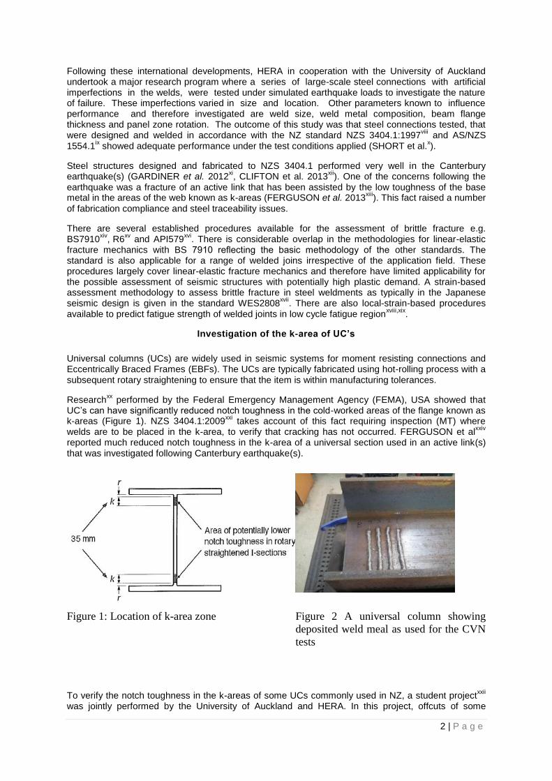
performed by the Federal Emergency Management Agency (FEMA), USA showed that UC’s can have significantly reduced notch toughness in the cold-worked areas of the flange known as k-areas (Figure 1). NZS 3404.1:2009
xxi takes account of this fact requiring inspection (MT) where
welds are to be placed in the k-area, to verify that cracking has not occurred. FERGUSON et alxxiv
reported much reduced notch toughness in the k-area of a universal section used in an active link(s) that was investigated following Canterbury earthquake(s).
Figure 1: Location of k-area zone
Figure 2 A universal column showing
deposited weld meal as used for the CVN
tests
To verify the notch toughness in the k-areas of some UCs commonly used in NZ, a student projectxxii
was jointly performed by the University of Auckland and HERA. In this project, offcuts of some
3 | P a g e
randomly selected UC’s of the following types have been tested: 200UC46.2, 200UC52.2, 250UC72.9, 310UC96.8 and 310UC118. The testing was done in the k-areas of the UCs in welded (Figure 2) and unwelded conditions to verify its possible effect.
The test data is reproduced in the Table 1 as reported in CHAU et alxxii
. Due to some inconsistency during machining of the samples and subsequent testing, the test data should be considered as indicative only.
Table 1: Average Charpy impact energy recorded in the web areas of universal columns
tested at 0°C, 10mmx5mm specimens
Area / CVN in J 200UC46.2 200UC52.2 250UC72.9 310UC96.8 310UC118
Welded K-Area 12.0 30.7 10.3 34.3 34.7
Non-Welded K-Area
21.7
30.3
19.7
42.3
22.0
Welded Web Centre
22.0
27.3
21.7
44.3
49.7
Non-Welded Web Centre
22.0
28.3
32.0
43.0
38.3
In the case of 200UC46.2 and 250UC72.9 the test results show a significant reduction in the CVN valued in the k-area in welded condition as compared with the tests performed in the central area of the web. In the case of 200UC52.2 and 310UC118 no apparent reduction in the CVN has been reported.
The effect of the notch toughness in the k-era of an active link on the brittle fracture reported below was assessed using a lowest measured CVN value of 10.3J@0C (10x5mm specimen)
The Approach
BS 7910 has been selected as the assessment standard as it can be applied to the range of welded joints irrespective of the application field. The standard provides a guideline for three levels of fracture assessments. The Level 2A assessment referred to as a normal assessment route for general applications has been selected. A tension Mode I has been considered.
The method is based on a Failure Assessment Diagram (FAD) as shown in the Figure 3. In the FAD
diagram, the fracture ratio rK is plotted along the y-axis and the load ratio, rL , is plotted along the
x-axis. The load ratio determines the danger of plastic collapse and the fracture ratio determines the danger of brittle fracture. For a combination of input parameters, the assessment point has to be placed within the limits of the FAD diagram in order to avoid brittle fracture.
The method does not take into account the strain hardening of the structural steels due to cyclic loading. In order to account for the pre-strain, the assessment procedure has been modified to include
a temperature shift in the JT27 transition temperature according to HYLANDxxiii
(Figure 4). The
reported tests have been performed on the 310UC158 flange steel. For the purpose of this assessment it was assumed that the test results are also valid for typical universal section 310UC118 350L0 to AS/NZS 3679.1 that was used in this analysis.
The temperature shift, ShiftT , is included in the model by the equation:
ShiftJ
Shift
J TTT 2727
4 | P a g e
where the temperature shift is expressed by
5397.17141.30415.02
prepreShiftT
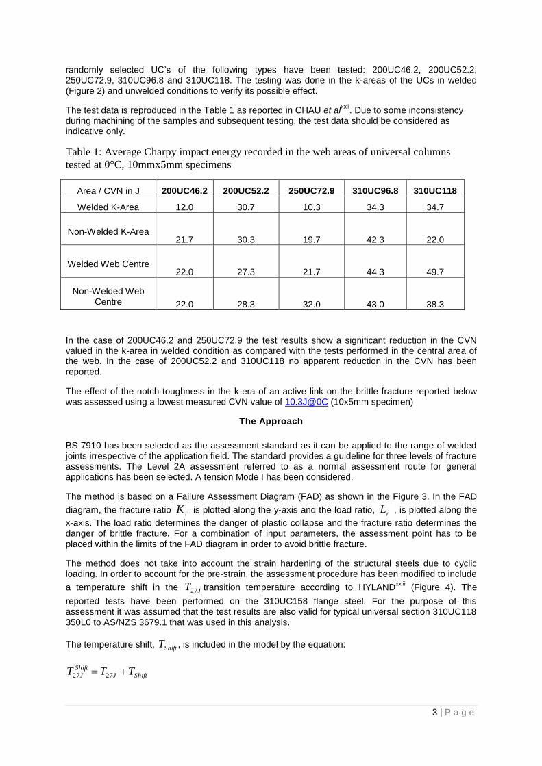
Here pre is the amount of pre strain that can be estimated (e.g according to the empirical data shown
in the Figure 3) or obtained from hardness measurements following a procedure outlined in FERGUSON et al
xxiv (Figure 5).
Figure 3: Schematic showing the effect of
number of cycles on the increase in transition
temperature according to SEALxxv
Figure 4: The effect of pre-strain on the
transition temperature according to
HYLANDxxvi
Figure 5: Hardness versus Plastic Strain
relationship for 8mm thick tensile
specimens according to H. Nashid reported
in FERGUSONxiii
Figure 6: Basic principle of a Failure
Assessment Diagram (FAD)
The assessment requires the knowledge of the peak stresses at the location of interest (weld toe and weld root). The peak stress at the weld toe was determined using the approach proposed by GLINKA et al.
xxvii. The approach is based on the decomposition of the hot spot stress into the membrane and
bending contribution.
The stress concentration factors are used together with the hot spot membrane and bending stress at the location of interest. The classical stress concentration factors according to LIDA et al.
xxviii were
0
0.2
0.4
0.6
0.8
1
1.2
1.4
0 0.2 0.4 0.6 0.8 1 1.2 1.4
K_r
L_r
Assessment Line
Cut-off Limit
Assessment Point
Not Acceptable
Acceptable
5 | P a g e
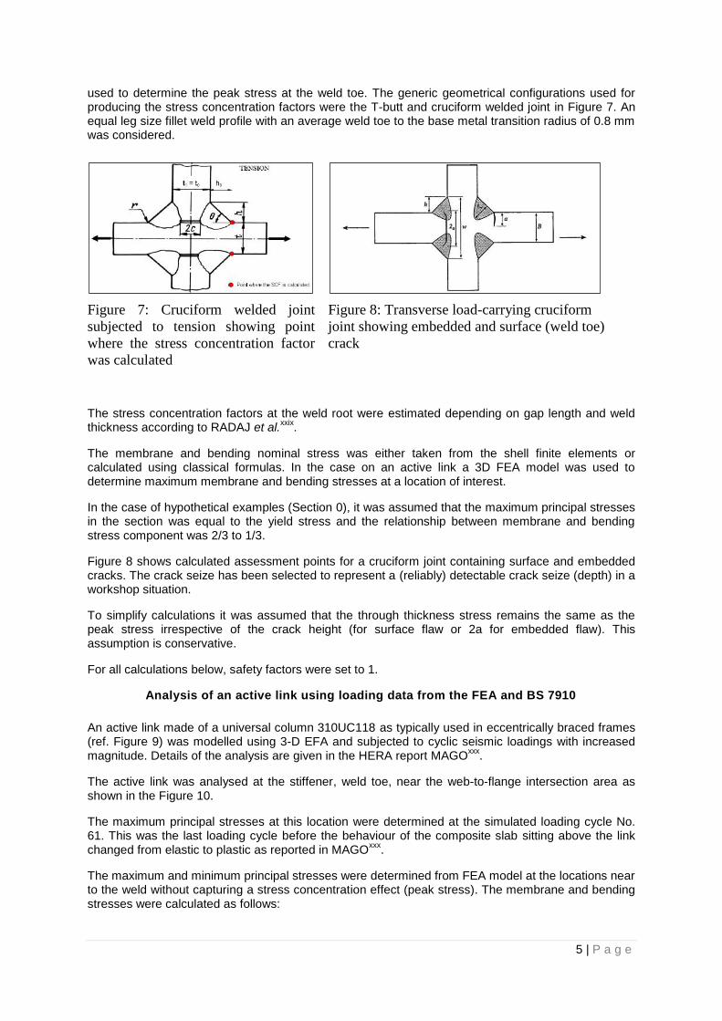
used to determine the peak stress at the weld toe. The generic geometrical configurations used for producing the stress concentration factors were the T-butt and cruciform welded joint in Figure 7. An equal leg size fillet weld profile with an average weld toe to the base metal transition radius of 0.8 mm was considered.
Figure 7: Cruciform welded joint
subjected to tension showing point
where the stress concentration factor
was calculated
Figure 8: Transverse load-carrying cruciform
joint showing embedded and surface (weld toe)
crack
The stress concentration factors at the weld root were estimated depending on gap length and weld thickness according to RADAJ et al.
xxix.
The membrane and bending nominal stress was either taken from the shell finite elements or calculated using classical formulas. In the case on an active link a 3D FEA model was used to determine maximum membrane and bending stresses at a location of interest.
In the case of hypothetical examples (Section 0), it was assumed that the maximum principal stresses in the section was equal to the yield stress and the relationship between membrane and bending stress component was 2/3 to 1/3.
Figure 8 shows calculated assessment points for a cruciform joint containing surface and embedded cracks. The crack seize has been selected to represent a (reliably) detectable crack seize (depth) in a workshop situation.
To simplify calculations it was assumed that the through thickness stress remains the same as the peak stress irrespective of the crack height (for surface flaw or 2a for embedded flaw). This assumption is conservative.
For all calculations below, safety factors were set to 1.
Analysis of an active link using loading data from the FEA and BS 7910
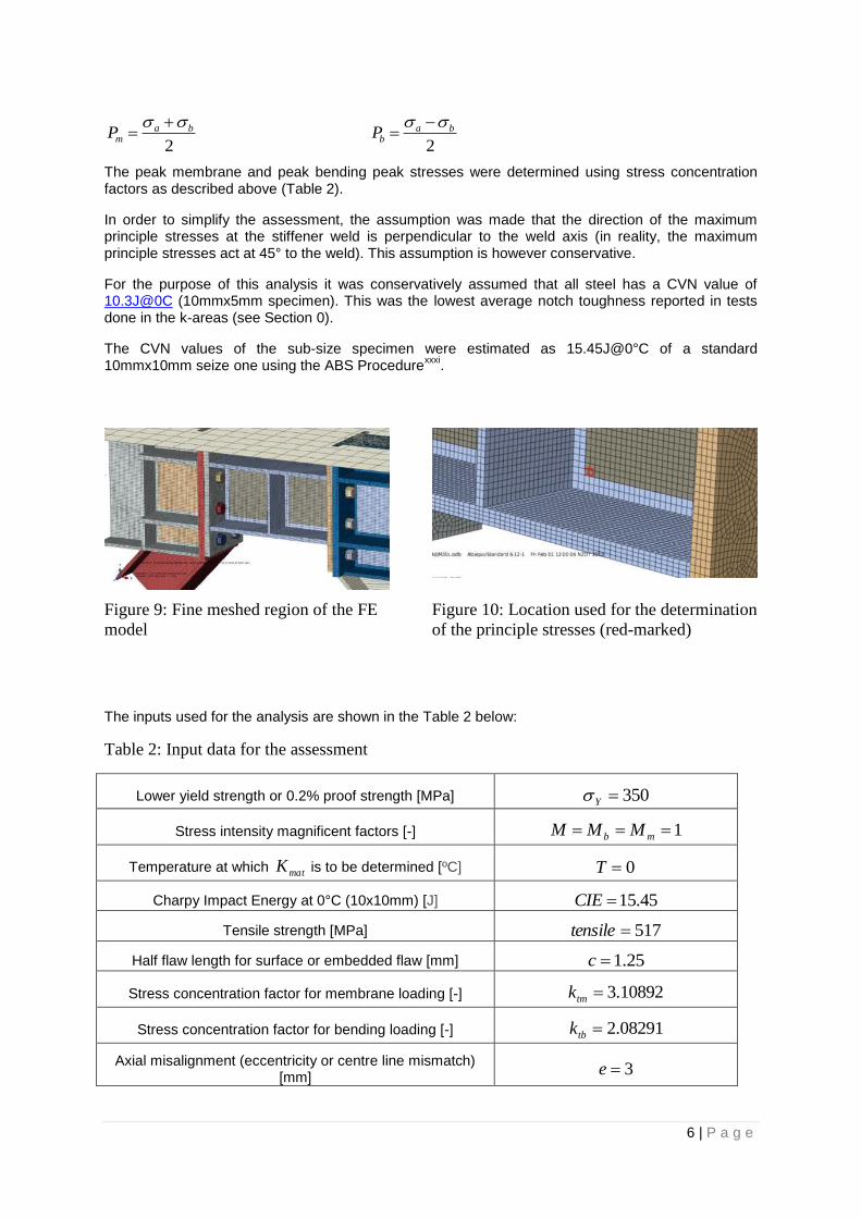
An active link made of a universal column 310UC118 as typically used in eccentrically braced frames (ref. Figure 9) was modelled using 3-D EFA and subjected to cyclic seismic loadings with increased magnitude. Details of the analysis are given in the HERA report MAGO
xxx.
The active link was analysed at the stiffener, weld toe, near the web-to-flange intersection area as shown in the Figure 10.
The maximum principal stresses at this location were determined at the simulated loading cycle No. 61. This was the last loading cycle before the behaviour of the composite slab sitting above the link changed from elastic to plastic as reported in MAGO
xxx.
The maximum and minimum principal stresses were determined from FEA model at the locations near to the weld without capturing a stress concentration effect (peak stress). The membrane and bending stresses were calculated as follows:
6 | P a g e
2
bamP
2
babP
The peak membrane and peak bending peak stresses were determined using stress concentration factors as described above (Table 2).
In order to simplify the assessment, the assumption was made that the direction of the maximum principle stresses at the stiffener weld is perpendicular to the weld axis (in reality, the maximum principle stresses act at 45° to the weld). This assumption is however conservative.
For the purpose of this analysis it was conservatively assumed that all steel has a CVN value of 10.3J@0C (10mmx5mm specimen). This was the lowest average notch toughness reported in tests done in the k-areas (see Section 0).
The CVN values of the sub-size specimen were estimated as 15.45J@0°C of a standard 10mmx10mm seize one using the ABS Procedure
xxxi.
Figure 9: Fine meshed region of the FE
model
Figure 10: Location used for the determination
of the principle stresses (red-marked)
The inputs used for the analysis are shown in the Table 2 below:
Table 2: Input data for the assessment
Lower yield strength or 0.2% proof strength [MPa] 350Y
Stress intensity magnificent factors [-] 1 mb MMM
Temperature at which matK is to be determined [ºC] 0T
Charpy Impact Energy at 0°C (10x10mm) [J] 45.15CIE
Tensile strength [MPa] 517tensile
Half flaw length for surface or embedded flaw [mm] 25.1c
Stress concentration factor for membrane loading [-] 10892.3tmk
Stress concentration factor for bending loading [-] 08291.2tbk
Axial misalignment (eccentricity or centre line mismatch) [mm]
3e
7 | P a g e
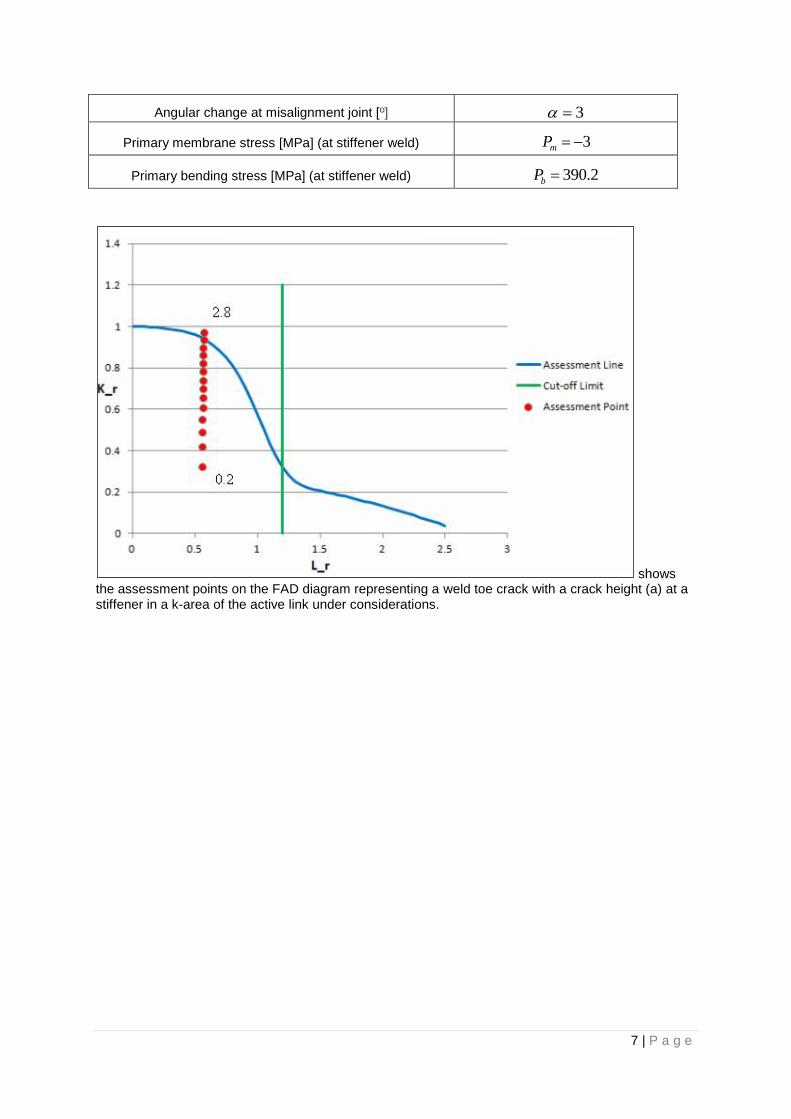
Angular change at misalignment joint [º] 3
Primary membrane stress [MPa] (at stiffener weld) 3mP
Primary bending stress [MPa] (at stiffener weld) 2.390bP
shows the assessment points on the FAD diagram representing a weld toe crack with a crack height (a) at a stiffener in a k-area of the active link under considerations.
8 | P a g e
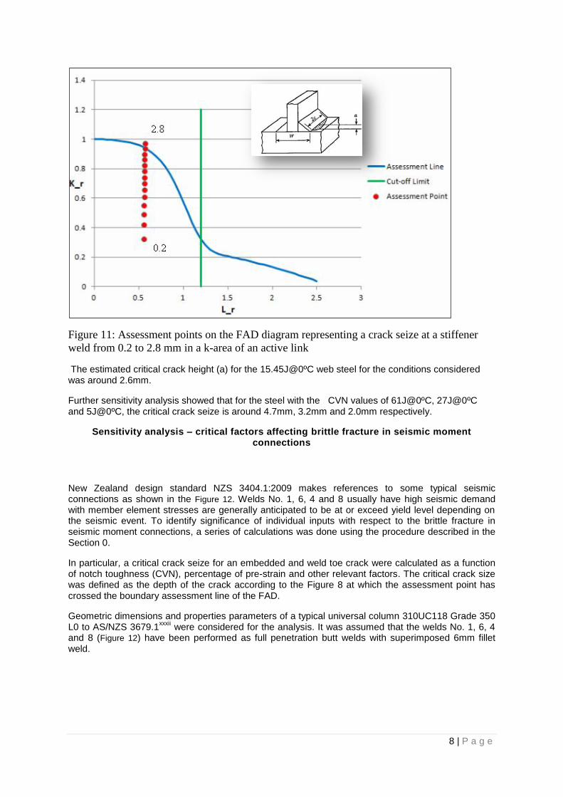
Figure 11: Assessment points on the FAD diagram representing a crack seize at a stiffener
weld from 0.2 to 2.8 mm in a k-area of an active link
The estimated critical crack height (a) for the 15.45J@0ºC web steel for the conditions considered was around 2.6mm.
Further sensitivity analysis showed that for the steel with the CVN values of 61J@0ºC, 27J@0ºC and 5J@0ºC, the critical crack seize is around 4.7mm, 3.2mm and 2.0mm respectively.
Sensitivity analysis – critical factors affecting brittle fracture in seismic moment connections
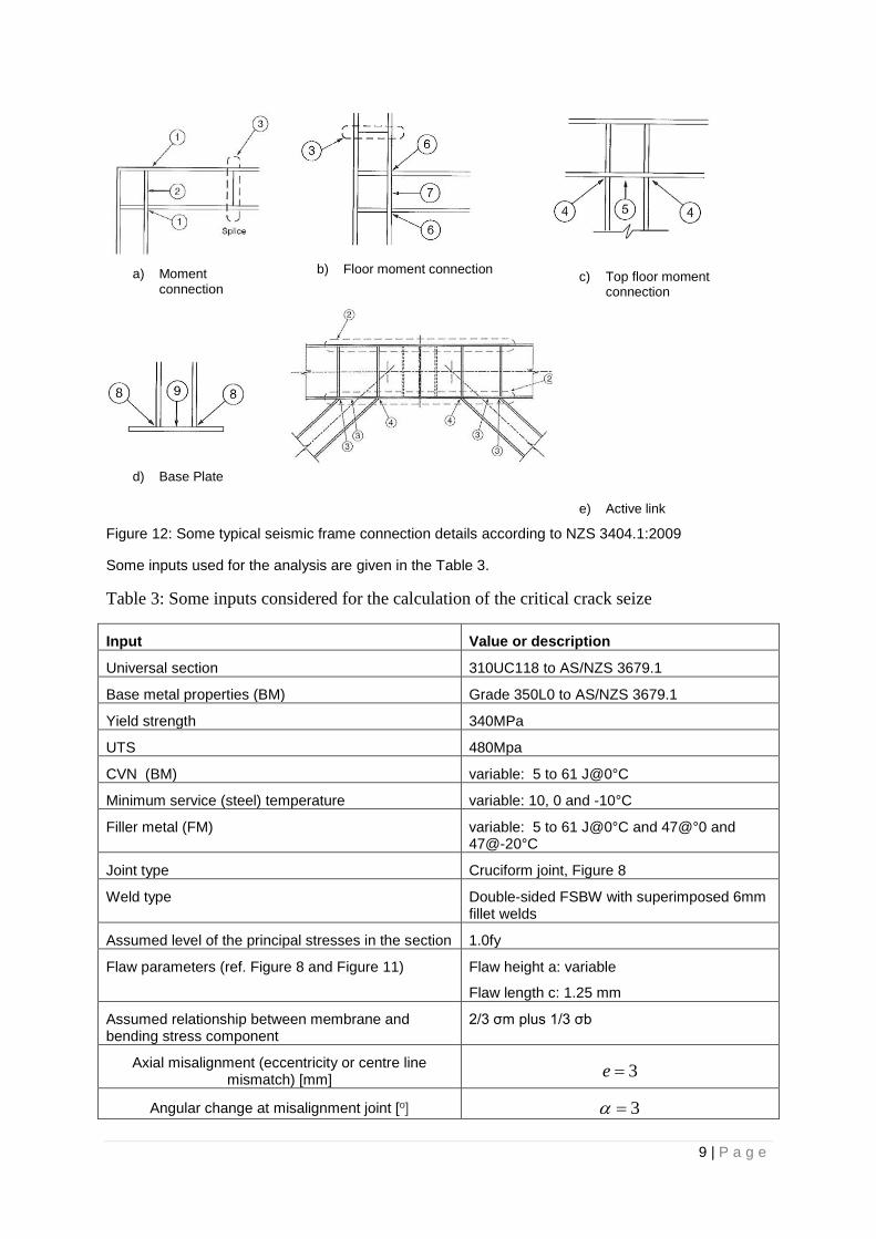
New Zealand design standard NZS 3404.1:2009 makes references to some typical seismic connections as shown in the Figure 12. Welds No. 1, 6, 4 and 8 usually have high seismic demand with member element stresses are generally anticipated to be at or exceed yield level depending on the seismic event. To identify significance of individual inputs with respect to the brittle fracture in seismic moment connections, a series of calculations was done using the procedure described in the Section 0.
In particular, a critical crack seize for an embedded and weld toe crack were calculated as a function of notch toughness (CVN), percentage of pre-strain and other relevant factors. The critical crack size was defined as the depth of the crack according to the Figure 8 at which the assessment point has crossed the boundary assessment line of the FAD.
Geometric dimensions and properties parameters of a typical universal column 310UC118 Grade 350 L0 to AS/NZS 3679.1
xxxii were considered for the analysis. It was assumed that the welds No. 1, 6, 4
and 8 (Figure 12) have been performed as full penetration butt welds with superimposed 6mm fillet weld.
9 | P a g e
a) Moment connection
b) Floor moment connection
c) Top floor moment connection
d) Base Plate
e) Active link
Figure 12: Some typical seismic frame connection details according to NZS 3404.1:2009
Some inputs used for the analysis are given in the Table 3.
Table 3: Some inputs considered for the calculation of the critical crack seize
Input Value or description
Universal section 310UC118 to AS/NZS 3679.1
Base metal properties (BM) Grade 350L0 to AS/NZS 3679.1
Yield strength 340MPa
UTS 480Mpa
CVN (BM) variable: 5 to 61 J@0°C
Minimum service (steel) temperature variable: 10, 0 and -10°C
Filler metal (FM) variable: 5 to 61 J@0°C and 47@°0 and 47@-20°C
Joint type Cruciform joint, Figure 8
Weld type Double-sided FSBW with superimposed 6mm fillet welds
Assumed level of the principal stresses in the section 1.0fy
Flaw parameters (ref. Figure 8 and Figure 11) Flaw height a: variable
Flaw length c: 1.25 mm
Assumed relationship between membrane and bending stress component
2/3 σm plus 1/3 σb
Axial misalignment (eccentricity or centre line mismatch) [mm]
3e
Angular change at misalignment joint [º] 3
10 | P a g e
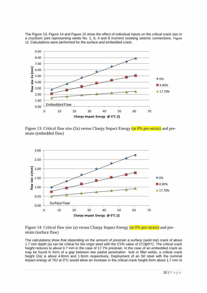
The Figure 13, Figure 14 and Figure 15 show the effect of individual inputs on the critical crack size in a cruciform joint representing welds No. 1, 6, 4 and 8 moment resisting seismic connections, Figure
12. Calculations were performed for the surface and embedded crack.
Figure 13: Critical flaw size (2a) versus Charpy Impact Energy (at 0% pre-strain) and pre-
strain (embedded flaw)
Figure 14: Critical flaw size (a) versus Charpy Impact Energy (at 0% pre-strain)-and pre-
strain (surface flaw)
The calculations show that depending on the amount of prestrain a surface (weld toe) crack of about 1.7 mm depth (a) can be critical for the virgin steel with the CVN value of 27J@0°C. The critical crack height reduces to about 0.7 mm in the case of 17.7% prestrain. In the case of an embedded crack as may be found in form of a gap between two partial penetration butt or fillet welds, a critical crack height (2a) is about 4.8mm and 1.9mm respectively. Deployment of an S0 steel with the nominal impact energy of 70J at 0°C would allow an increase in the critical crack height form about 1.7 mm to
0.00
1.00
2.00
3.00
4.00
5.00
6.00
7.00
8.00
9.00
0 10 20 30 40 50 60 70
Flaw
siz
e 2
a [m
m]
Charpy Impact Energy @ 0°C [J]
0%
4.90%
17.70%
Embedded Flaw
0.00
0.50
1.00
1.50
2.00
2.50
3.00
0 10 20 30 40 50 60 70
Flaw
siz
e a
[m
m]
Charpy Impact Energy @ 0°C [J]
0%
4.90%
17.70%
Surface Flaw
11 | P a g e
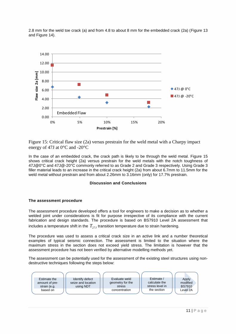
2.8 mm for the weld toe crack (a) and from 4.8 to about 8 mm for the embedded crack (2a) (Figure 13 and Figure 14).
Figure 15: Critical flaw size (2a) versus prestrain for the weld metal with a Charpy impact
energy of 47J at 0°C and -20°C
In the case of an embedded crack, the crack path is likely to be through the weld metal. Figure 15 shows critical crack height (2a) versus prestrain for the weld metals with the notch toughness of 47J@0°C and 47J@-20°C commonly referred to as Grade 2 and Grade 3 respectively. Using Grade 3 filler material leads to an increase in the critical crack height (2a) from about 6.7mm to 11.5mm for the weld metal without prestrain and from about 2.26mm to 3.16mm (only) for 17.7% prestrain.
Discussion and Conclusions
The assessment procedure
The assessment procedure developed offers a tool for engineers to make a decision as to whether a welded joint under considerations is fit for purpose irrespective of its compliance with the current fabrication and design standards. The procedure is based on BS7910 Level 2A assessment that
includes a temperature shift in the JT27 transition temperature due to strain hardening.
The procedure was used to assess a critical crack size in an active link and a number theoretical examples of typical seismic connection. The assessment is limited to the situation where the maximum stress in the section does not exceed yield stress. The limitation is however that the assessment procedure has not been verified by alternative modelling methods yet.
The assessment can be potentially used for the assessment of the existing steel structures using non-destructive techniques following the steps below:
0.00
2.00
4.00
6.00
8.00
10.00
12.00
14.00
0% 5% 10% 15% 20%
Flaw
siz
e 2
a [m
m]
Prestrain [%]
47J @ 0°C
47J @ -20°C
Embedded Flaw
Estimate the amount of pre-
strain (e.g. based on hardness)
measurements
Identify defect seize and location
using NDT
Evaluate weld geometry for the
stress concentration
factors
Apply modified BS7910 Level 2A
asessment
Estimate / calculate the stress level in
the section
12 | P a g e
Tests in the k-area of universal columns
Charpy impact tests performed on some typical universal columns show in the case of 250UC72.9 an almost three-fold reduction in the CVN in the k-area as compared with the centreline of the web. Due to some inconsistency during machining and testing, the test results should be considered as indicative only. The tests should be repeated under the controlled conditions. This should also include a distribution of the CVN values as a function of beam length to capture possible scattering of the cold-worked areas along the beam. However, calculations below show that the notch toughness of the web is not as critical as that of the flange metal.
Evaluation of an active link at the stiffener
The assessment of an active link shows an estimated critical crack seize (depth) at a stiffener of an active link that exhibits an average CVN value of 15.45J@0ºC for the loading case considered was around 2.6mm. Even 5J@0ºC steel will be able to resist propagation of an up to 2.0mm deep crack under the loading conditions considered.
A crack of this depth can be reliably detected by the surface inspection methods. From the practical point of view it means that, a universal beam with the lower impact toughness in the web area can be accepted as fit for purpose for this application provided there is no surface braking (weld toe) cracks.
Sensitivity analysis of factors affecting brittle fracture in seismic moment connections
Alongside with the crack size, component temperatures and strain-hardening are the significant impact factors affecting brittle fracture. However the crack size (depth) has the most significant impact implying that the quality control during welding fabrication is a vital step alongside with material traceability.
Using higher toughness filler material significantly improves fracture resistance of a cruciform welded joint. Grade 3 filler material shall be specified for all critical welds as required in NZS 3404.1.
The critical crack size for the embedded crack was always smaller than the gap between two fillet welds indicating that specifying fillet welds for the moment resisting seismic connections may not be conservative. Welds used to connect beams to columns in Moment Resisting Connections (MRCs) and designed to resist seismic loads are usually butt welds. The New Zealand structural steel design code however permits the use of fillet welds which are commonly considered more economic for sections with beam flange thicknesses less than 15 mm.
SP weld category (ref. AS/NZS 1554.1 Table 6.2.2) permits a short surface crack-like imperfection referred to as “Lack of fusion or incomplete penetration” with a length of up to 20mm and a depth of up to 1.5mm depending on the material thickness and the location of the imperfection relative to the end of the weld. Depending on the notch toughness of the BM this imperfection may be critical for moment-resisting connections from the brittle fracture point of view.
Recommendations
Following recommendations can be given:
a) Suitability of fillet welds for the moment connections needs to be re-considered (gap=crack). b) Acceptability of a lack of fusion as a surface imperfection for SP weld to AS/NZS 1554.1
should be re-considered. c) AISC
xxxiii & AWSD1.18
xxxiv approach that is more prescriptive regarding weld details and QA
needs to be re-considered with respect to the applicability of some of the aspects to NZ practices (e.g. welding in the corner area, coping holes etc.).
d) A guidance should be given to the engineers addressing NDT requirements as a function of critical defect size, material properties, service conditions and probability of detection and well as welding QA.
e) An auditable welding quality management system according to NZS 3404.1 and AS/NZS 1554.1, and/or AS/NZS ISO 3834
xxxv needs to be considered as a mandatory requirement for
fabricators involved in welding of critical seismic connections.
13 | P a g e
Acknowledgement
The authors would like to thank Prof. K. Jayaraman, Prof. Ch. Clifton, Mr H. Nashid, Mr J. Chau and J. Shin from the University of Auckland, Mr A. McClintock and H. Heinzel from HERA, Grayson Engineering Ltd and other people and companies who have contributed to this project.
REFERENCES
i FEMA-350, Recommended Seismic Design Criteria for New Steel Moment –Frame Buildings, June 2000.
ii FEMA-351, Recommended Seismic Evaluation and Upgrade Criteria for Existing Welded Steel
Moment –Frame Buildings, June 2000.
iii FEMA-352, Recommended Post Earthquake Evaluation and Repair Criteria for Welded Steel
Moment –Frame Buildings, June 2000.
iv FEMA-353, Recommended Specifications and Quality Assurance Guidelines for Steel Moment –
Frame Construction for Seismic Applications, June 2000.
v FEMA-355A to E, State of the Art Reports on Various Aspects of Behaviour of Steel Moment-Frame
Buildings Subjected to Seismic Loading, September 2000.
vi Japanese Standard AIJ 2001, Recommendations for the Design of Connections of Steel Structures,
Architectural Institute of Japan, Tokyo, Japan, in Japanese
vii Japanese Welding Engineering Society Report, WES TR 2808:2000, on Method for
Assessment of Brittle Fracture in Steel Weldments Subject to Cyclic and Dynamic Large Straining.
viii NZS 3404.1:1997 Steel Structures.
ix AS/NZS 1554.1:2011 Structural Steel Welding. Part 1: Welding of steel structures
x Andrew Short et al.: Earthquake Performance of Welded Moment Resisting Connections. NEW
ZEALAND WELDING CENTRE REPORT R8-28. 2004
xi Sean Gardiner, G. Charles Clifton , Gregory A MacRae: Performance, damage assessment and
repair of multi-storey eccentrically braced framed building following the Christchurch earthquake series. SESOC NZ Conference 2-3 November 2012.
xii G. C. Clifton and G. A. MacRae: New insights into steel building performance from the Christchurch
natural laboratory. Steel Innovations Conference 2013 Christchurch, New Zealand 21-22 February 2013
14 | P a g e
xiii W. G. Ferguson, H. Nashid, G.C. Clifton, M V Kral, S. Lopert and G MacRae: The Performance and
Remnant Life of Structural Steel in an Earthquake Damaged Building. Steel Innovations Conference 2013 Christchurch, New Zealand 21-22 February 2013
xiv BS7910: 2005 - Guide to Methods for Assessing the Acceptability of Flaws in Metallic Structures,
BSI 2005.
xv R6 Rev4 —Assessment of Integrity of Structures containing Defects, British Energy EDF, 2012
xvi API-579-1/ASME FFS-1, Fitness-For-Service, American Petroleum Institute — American Society of
Mechanical Engineers, 2007.
xvii WES 2808:2003 Method of assessing brittle fracture in steel weldments subjected to large cyclic
and dynamic strain
xviii Kazuo TATEISHI et al.: Low cycle fatigue assessment for welded joints based on local strain
approach. IIW Document XIII-2160-07
xix Kawin SAIPRASERTKIT , Takeshi HANJI and Chitoshi MIKI: Fatigue strength assessment of load
arrying cruciform joints in low and high cycle fatigue region based on effective notch concept. IIW Document XIII-2384-11
xx FEMA Report, "FEMA-355A State of the Art Report on Base Metals and Fracture. FEMA2000.
xxi NZS 3404.1:2009 Steel structures Standard – Part 1: Materials, fabrication, and construction
xxii J. Chau, J. Shin; Investigation of the effects of welding in the k-area of steel beams in NZ
structures; 2013
xxiii Clark William Keith Hyland; Assessment of ductile endurance of earthquake resisting steel
members; 2008
xxiv W. G. Ferguson, H. Nashid, G. C. Clifton, M. V. Kral, S. Lopert, G. MacRae; The Performance and
Remnant Life of Structural Steel in an Earthquake Damaged Building; 2013
xxv C. K. Seal: Cyclic Plasticity of Steel under Seismic Load Condition. PhD Thesis, The University of
Auckland 2009.
xxvi C. W. K. Hyland: Assessment of ductile endurance of Earthquake Resisting Steel Members. PhD
Thesis, The University of Auckland, 2008.
xxvii G. Glinka et al.: Stress analysis and fatigue life assessment of welded structures. IIW Document
XIII-2319-10

15 | P a g e
xxviii K. Iida and T. Uemura, Stress Concentration Factor Formulas Widely Used in Japan, The
International Welding Institute, Document IIW XIII-1530-94, 1994
xxix D. Radaj and C.M. Sonsino: Fatigue Assessment of Welded Joints by Local Approaches.
Woodhead Publishing 1998.
xxx N. Mago: Finite element analysis of eccentrically braced frames with removable link; HERA Report;
2013
xxxi American Bureau of Shipping; Rules for materials and welding – Part 2; ABS; 2012
xxxii AS/NZS 3679.1:2010 Structural steel - Hot-rolled bars and sections
xxxiii AISC: The Seismic Design Manual. The American Institute of Steel Construction
xxxiv AWS D1.8 Structural Welding Code - Seismic Supplement. AWS, USA.
xxxv AS/NZS ISO 3834 Part 1 to Part 5: Quality requirements for fusion welding of metallic materials


![IN THE HIGH COURT OF NEW ZEALAND AUCKLAND REGISTRY … · SKP INCORPORATED v AUCKLAND COUNCIL [2019] NZHC 900 [24 April 2019] IN THE HIGH COURT OF NEW ZEALAND AUCKLAND REGISTRY I](https://img.pdfslide.net/doc/110x75/5ea612508dc1ec5f595fe327/in-the-high-court-of-new-zealand-auckland-registry-skp-incorporated-v-auckland-council.jpg)