Embed Size (px)
Citation preview
59
The RIBA Journal October 2014
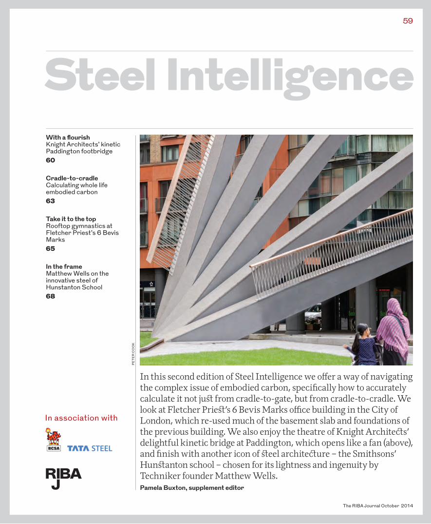
In this second edition of Steel Intelligence we offer a way of navigating the complex issue of embodied carbon, specifically how to accurately calculate it not just from cradle-to-gate, but from cradle-to-cradle. We look at Fletcher Priest’s 6 Bevis Marks office building in the City of London, which re-used much of the basement slab and foundations of the previous building. We also enjoy the theatre of Knight Architects’ delightful kinetic bridge at Paddington, which opens like a fan (above), and finish with another icon of steel architecture – the Smithsons’ Hunstanton school – chosen for its lightness and ingenuity by Techniker founder Matthew Wells.Pamela Buxton, supplement editor
PE
TE
R C
OO
K
Steel IntelligenceWith a flourish Knight Architects’ kinetic Paddington footbridge 60
Cradle-to-cradle Calculating whole life embodied carbon 63
Take it to the top Rooftop gymnastics at Fletcher Priest’s 6 Bevis Marks 65
In the frame Matthew Wells on the innovative steel of Hunstanton School 68
In association with
The RIBA Journal October 2014
60 Steel IntelligenceMerchant Square footbridge
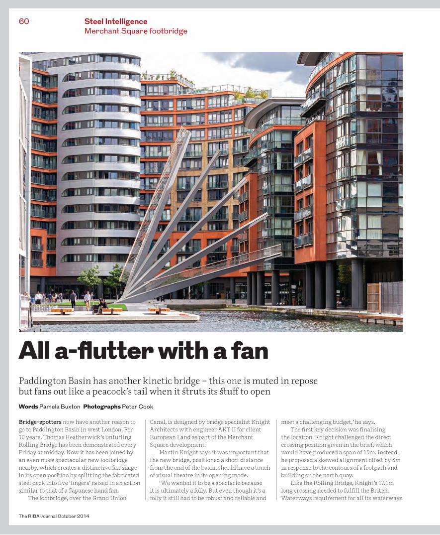
Bridge-spotters now have another reason to go to Paddington Basin in west London. For 10 years, Thomas Heatherwick’s unfurling Rolling Bridge has been demonstrated every Friday at midday. Now it has been joined by an even more spectacular new footbridge nearby, which creates a distinctive fan shape in its open position by splitting the fabricated steel deck into five ‘fingers’ raised in an action similar to that of a Japanese hand fan.
The footbridge, over the Grand Union
Canal, is designed by bridge specialist Knight Architects with engineer AKT II for client European Land as part of the Merchant Square development.
Martin Knight says it was important that the new bridge, positioned a short distance from the end of the basin, should have a touch of visual theatre in its opening mode.
‘We wanted it to be a spectacle because it is ultimately a folly. But even though it’s a folly it still had to be robust and reliable and
meet a challenging budget,’ he says.The first key decision was finalising
the location. Knight challenged the direct crossing position given in the brief, which would have produced a span of 15m. Instead, he proposed a skewed alignment offset by 3m in response to the contours of a footpath and building on the north quay.
Like the Rolling Bridge, Knight’s 17.1m long crossing needed to fulfill the British Waterways requirement for all its waterways
All a-flutter with a fanPaddington Basin has another kinetic bridge – this one is muted in repose but fans out like a peacock’s tail when it struts its stuff to openWords Pamela Buxton Photographs Peter Cook
61
The RIBA Journal October 2014
to be navigable. This left the designer with three main choices: a fixed elevated bridge, a horizontally opening swing bridge, or a vertically opening bridge.
The elevated option had the disadvantage of taking people away from the quayside and would lead to land ownership issues on the south quay. A swing bridge would also take out use of some of the quayside, and would crucially lack drama. In particular, Knight thought the side-opening mechanism would be too resonant of the 20m long narrow boats that manouvered at the end of the basin.
The chosen option is a far more exciting vertical-opening design achieved by a hydraulically operated hinged bascule mechanism, supported primarily from the north quay. To develop the design, the engineer and architect used Rhino with a Grasshopper modelling plug-in.
‘Through these an extremely lightweight and economic structure was achieved, based on an outer plate thickness of 10mm and an internal ribbing of 10mm plates,’ says AKT II director Daniel Bosia.
For the vast majority of the time, the bridge is closed, clearing the high tide by just 100mm to give a sense of walking on water. In this position, the bridge is sober in appearance, each deck beam slotting down onto a conical-tipped steel bar on a shelf on the southern quay. The most visible element is not the bridge deck itself but the integral five steel counterweights on the northern quay which balance the cantilevers. These counterweights, says Knight, are conceived as sculptural objects in the landscape that give a clue to the raised form of the bridge. A great deal of deliberation went into their scale – they needed to be visible but don’t compete in any way with the main event.
‘There’s something nice about the understated quality of the bridge
compared to the drama of when it’s open... We didn’t want a peacock there all the time,’ says Knight.
The fabricated, 600mm wide trapezoid box girders are tapered from 900mm deep at the pivot point on the north of the quay to 300mm at the tip on the other side. These lock together laterally to form a rigid, single deck. One of the challenges was achieving only the narrowest of gaps – the client was adamant that there would be no danger of anyone catching a heel in the gap or of a glimpse of the water beneath. Each has a stainless steel edge strip which contains anti-skid surfacing.
‘The 0-3mm tolerance required was very difficult to achieve for a moving bridge with pivoting,’ says Mark Randerson, operations director of S H Structures.
As the bridge deck is raised by the hydraulic mechanism, the counterweights rotate down flush into the ground. Added spectacle is created by splitting the 3m wide deck into five parallel, equal beams that rise intentionally slowly in a graduated, sequenced flourish from 67° to 16°. This lowest
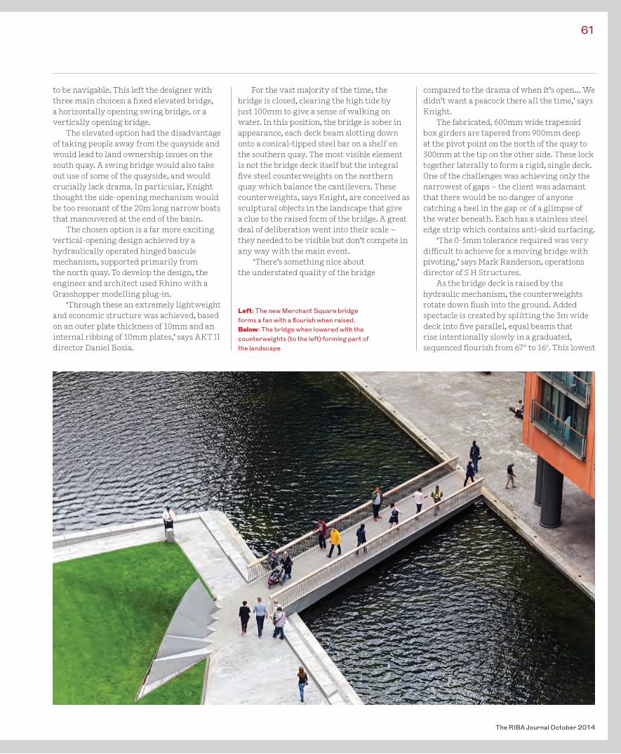
Left: The new Merchant Square bridge forms a fan with a flourish when raised.Below: The bridge when lowered with the counterweights (to the left) forming part of the landscape
beam achieves the required clearance at mid channel. The design allows each beam to move in windy conditions and to avoid any contact by offsetting the axis of rotation by 784mm between each finger. Each beam moves faster than the next to co-ordinate the fanning effect during the opening sequence, with manual override possible if necessary.
‘We wanted it to look as simple and minimal as possible, but to make something that minimal is much harder,’ says AKT II director Daniel Bosia.
The bridge has epoxy resin decking in charcoal grey to match the quayside paving, with tubular stainless steel balustrades and a timber handrail. The balustrades, says Knight, gives a comforting sense of enclosure when looking along the bridge but still allow a degree of transparency when the bridge is viewed side on from the ends of the dock.
At night, the bridge is lit by LEDs beneath the handrail and strip lights between each counterweight to wash light up onto the sculptural forms.
One of the biggest challenges was installation. Because of limited vehicular access to the basin, the steelwork was
prefitted in the fabrication shop with its pivots, pistons and bearing plates to ensure a very tight tolerance. It was then disassembled and brought to site by barge, arranged on the vessel with the highest point in the middle to ensure that it would clear the vaulted bridges en route.
A separate project by Townshend Landscape Architects integrates the counterweights into the landscape design for a quayside terrace.
‘One of the real challenges, and the beauty of the project, is that everything is bespoke,’ says Knight. ‘The idea is unique and the solution is unique, with everything thought through from first principles. It’s very rewarding.’
Soon more buildings will be constructed at Merchant Square, including a high-rise designed by Robin Partington & Partners – adding to the collection of offices by Richard Rogers Partnership, Terry Farrell & Partners and Mossessian & Partners. These new buildings will bring increased footfall across the new bridge and an even greater potential audience for the regular Friday lifting of both of Paddington Basin’s kinetic bridges. •
The RIBA Journal October 2014
62 Steel IntelligenceMerchant Square footbridge
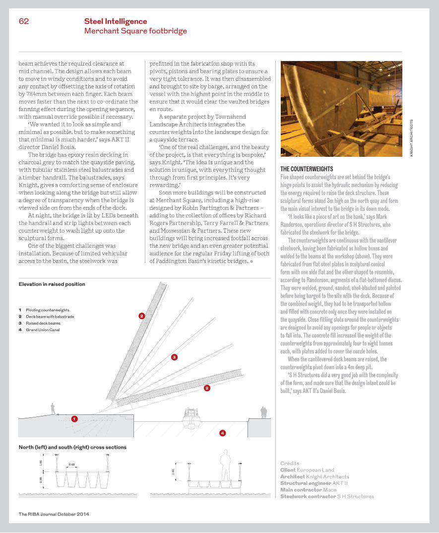
THE COUNTERWEIGHTSFive shaped counterweights are set behind the bridge’s hinge points to assist the hydraulic mechanism by reducing the energy required to raise the deck structure. These sculptural forms stand 3m high on the north quay and form the main visual interest to the bridge in its down mode.
‘It looks like a piece of art on the bank,’ says Mark Randerson, operations director of S H Structures, who fabricated the steelwork for the bridge.
The counterweights are continuous with the cantilever steelwork, having been fabricated as hollow boxes and welded to the beams at the workshop (above). They were fabricated from flat steel plates in sculptural conical form with one side flat and the other shaped to resemble, according to Randerson, segments of a flat-bottomed discus. They were welded, ground, sanded, shot-blasted and painted before being barged to the site with the deck. Because of the combined weight, they had to be transported hollow and filled with concrete only once they were installed on the quayside. Close fitting slots around the counterweights are designed to avoid any openings for people or objects to fall into. The concrete fill increased the weight of the counterweights from approximately four to eight tonnes each, with plates added to cover the nozzle holes.
When the cantilevered deck beams are raised, the counterweights pivot down into a 4m deep pit.
‘S H Structures did a very good job with the complexity of the form, and made sure that the design intent could be built,’ says AKT II’s Daniel Bosia.
CreditsClient European LandArchitect Knight ArchitectsStructural engineer AKT IIMain contractor MaceSteelwork contractor S H Structures
cross section north
1.00
1.00
0.90
0.60
cross section south
1.10
0.81
0.60
1.10
1.10
0.81
0.60
1.10
KN
IGH
T A
RC
HIT
EC
TS
Elevation in raised position
1
2
4
3
North (left) and south (right) cross sections
1 Pivoting counterweights2 Deck beam with balustrade 3 Raised deck beams4 Grand Union Canal
2
Steel IntelligenceEmbodied carbon Steel IntelligenceEmbodied carbon
As the operational efficiency of buildings improves, the relative proportion of embodied carbon within the total emissions is rising. As a result, embodied carbon is coming under greater scrutiny as part of the drive to meet government targets for reducing CO2
emissions by 80% by 2050.
Know your definitionsEmbodied carbon has become synonymous with the term carbon footprint. This refers to the lifecycle greenhouse gas emissions during
manufacture and transport of construction materials and components, plus the construction process and end-of-life aspects of the building. It is expressed as carbon dioxide equivalents – CO2e – and is separate to operational carbon, which is the CO2 emitted during a building’s operational phase, such as from heating, cooling, ventilation and lighting. A building’s total emissions are a combination of embodied and operational carbon.
It is important to be clear on popular
63
The RIBA Journal October 2014
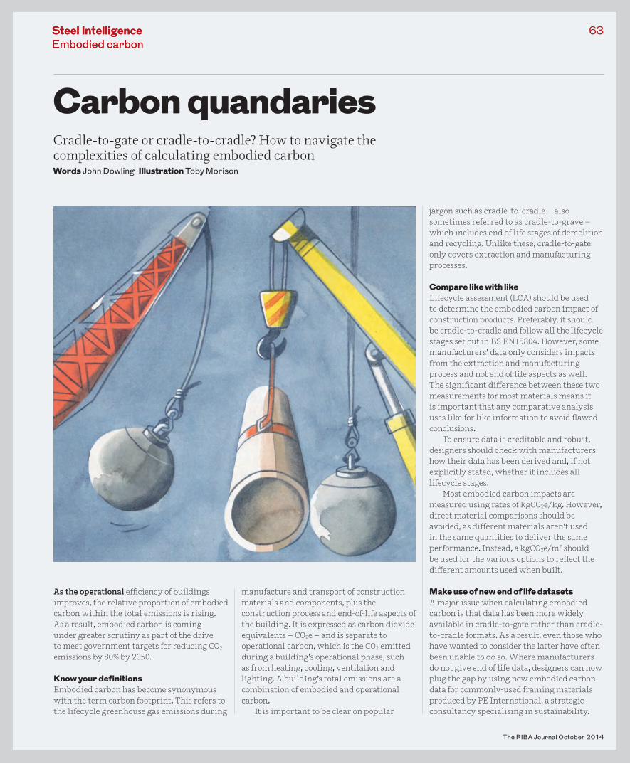
Carbon quandariesCradle-to-gate or cradle-to-cradle? How to navigate the complexities of calculating embodied carbonWords John Dowling Illustration Toby Morison
jargon such as cradle-to-cradle – also sometimes referred to as cradle-to-grave – which includes end of life stages of demolition and recycling. Unlike these, cradle-to-gate only covers extraction and manufacturing processes.
Compare like with likeLifecycle assessment (LCA) should be used to determine the embodied carbon impact of construction products. Preferably, it should be cradle-to-cradle and follow all the lifecycle stages set out in BS EN15804. However, some manufacturers’ data only considers impacts from the extraction and manufacturing process and not end of life aspects as well. The significant difference between these two measurements for most materials means it is important that any comparative analysis uses like for like information to avoid flawed conclusions.
To ensure data is creditable and robust, designers should check with manufacturers how their data has been derived and, if not explicitly stated, whether it includes all lifecycle stages.
Most embodied carbon impacts are measured using rates of kgCO2e/kg. However, direct material comparisons should be avoided, as different materials aren’t used in the same quantities to deliver the same performance. Instead, a kgCO2e/m2 should be used for the various options to reflect the different amounts used when built.
Make use of new end of life datasetsA major issue when calculating embodied carbon is that data has been more widely available in cradle-to-gate rather than cradle-to-cradle formats. As a result, even those who have wanted to consider the latter have often been unable to do so. Where manufacturers do not give end of life data, designers can now plug the gap by using new embodied carbon data for commonly-used framing materials produced by PE International, a strategic consultancy specialising in sustainability.
This data set was overseen by Jane Anderson, lead author of the BRE’s Green Guides to Specification. The table below is an extract from the PE International data, covering demolition and recycling impacts for common construction materials (BS EN15804 modules C and D) and includes robust comparative data for extraction and manufacturing lifecycle stages too.
Calculate embodied carbon footprints onlineTata Steel and the BCSA have developed an online tool to assist in estimating the embodied carbon footprint for a multi-storey superstructure as part of a new guide on the subject. The tool can auto generate a CO2e figure using algorithms developed by the Steel Construction Institute, or can be used with manual inputs specific to the designer’s building. This manual option also enables a comparison to be made between the impact of a steel and concrete framed building.
The carbon emissions rates used in the tool can alternatively be incorporated into the designer’s own spreadsheet. •John Dowling is sustainability manager of the British Constructional Steelwork Association and author of the Tata Steel and British Constructional Steelwork Association’s new guide to calculating embodied carbon. Steel Construction: Embodied Carbon is available to download at www.steelconstruction.info. An extended version of the table below is also available online.
The RIBA Journal October 2014
64
SPECIFICS, MINDSETS, AND A HOLISTIC APPROACHArchitects specialising in sustainability discuss some of the issues they encounter when calculating embodied carbon.
Stewart Dodd, managing director, Satellite ArchitectsEmbodied energy is a minefield. There are so many bits of data out there that contradict each other. The major problem is that it’s so subjective you rarely end up with any true information. BRE databases can give you a broad brush idea but you really need an analysis of your particular building to get the true picture, and that’s where the cost comes in.
Duncan Baker-Brown, director, BBM Sustainable DesignYou can’t analyse embodied carbon without looking at things holistically. Architects and specifiers need to understand the relative embodied carbon values of the most commonly used materials in principle, but then it’s all about how they detail and construct a building so that any components that might have high embodied carbon can be easily re-used.
Anna Woodeson, head of sustainability, Wilkinson EyreAs an industry we’ve just about cracked calculating embodied energy, although it’s clear there’s no one single approach. What’s interesting is how we then use that information to adapt our designs. We’ve started analysing embodied carbon in detail on some of our projects and as soon as you start questioning it, you begin to get a different mindset and start to pare back and simplify the design and the use of materials.
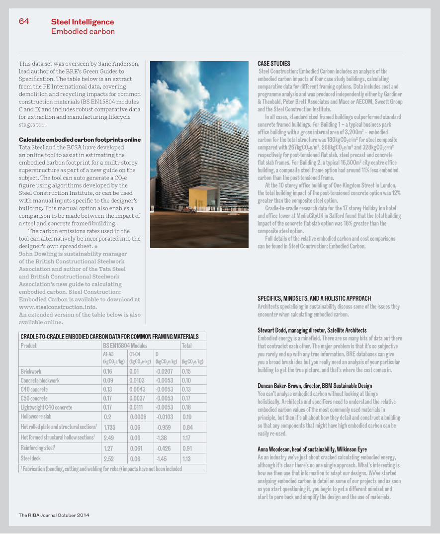
CRADLE-TO-CRADLE EMBODIED CARBON DATA FOR COMMON FRAMING MATERIALSProduct BS EN15804 Modules Total
A1-A3(kgCO2e/kg)
C1-C4(kgCO2e/kg)
D(kgCO2e/kg) (kgCO2e/kg)
Brickwork 0.16 0.01 -0.0207 0.15Concrete blockwork 0.09 0.0103 -0.0053 0.10C40 concrete 0.13 0.0043 -0.0053 0.13C50 concrete 0.17 0.0037 -0.0053 0.17Lightweight C40 concrete 0.17 0.0111 -0.0053 0.18Hollowcore slab 0.2 0.0006 -0.0103 0.19Hot rolled plate and structural sections1 1.735 0.06 -0.959 0.84Hot formed structural hollow sections1 2.49 0.06 -1.38 1.17Reinforcing steel1 1.27 0.061 -0.426 0.91Steel deck 2.52 0.06 -1.45 1.131 Fabrication (bending, cutting and welding for rebar) impacts have not been included
CASE STUDIES Steel Construction: Embodied Carbon includes an analysis of the embodied carbon impacts of four case study buildings, calculating comparative data for different framing options. Data includes cost and programme analysis and was produced independently either by Gardiner & Theobald, Peter Brett Associates and Mace or AECOM, Sweett Group and the Steel Construction Institute.
In all cases, standard steel framed buildings outperformed standard concrete framed buildings. For Building 1 – a typical business park office building with a gross internal area of 3,200m2 – embodied carbon for the total structure was 180kgCO2e/m² for steel composite compared with 267kgCO2e/m², 268kgCO2e/m² and 328kgCO2e/m² respectively for post-tensioned flat slab, steel precast and concrete flat slab frames. For Building 2, a typical 16,500m2 city centre office building, a composite steel frame option had around 11% less embodied carbon than the post-tensioned frame.
At the 10 storey office building of One Kingdom Street in London, the total building impact of the post-tensioned concrete option was 12% greater than the composite steel option.
Cradle-to-cradle research data for the 17 storey Holiday Inn hotel and office tower at MediaCityUK in Salford found that the total building impact of the concrete flat slab option was 18% greater than the composite steel option.
Full details of the relative embodied carbon and cost comparisons can be found in Steel Construction: Embodied Carbon.
Steel IntelligenceEmbodied carbon
Steel IntelligenceBevis Marks
At just 16 storeys high, 6 Bevis Marks is relatively diminutive compared with the many new towers now dominating the City of London skyline.
The Fletcher Priest-designed office development is dwarfed by the adjacent Swiss Re ‘Gherkin’ and nearby Leadenhall ‘Cheesegrater’, and at 52.4m is nowhere near tall enough to attract a nickname of its own yet. But there are ways other than height to create distinctiveness on the skyline – in this case a steel and ETFE rooftop canopy that wraps over the 21,370m2 building to capture an all-weather roof terrace, before continuing in a lattice down the side.
The site was occupied by a 1980s eight-storey structure, and client AXA Real Estate & MGPA naturally wanted to maximise its potential with a much larger development. After experimenting with several massing options, Fletcher Priest designed a 15 storey tower that steps down to 11. The footprint is slightly reduced from 27.5m to 24.5m to maximise public space on Bevis Marks, with new pedestrian links created from the rear to Bury Court and the Swiss Re building.
But while the top of the £52m building grabs attention, it’s what’s going on at the bottom that provides the key to the whole scheme.
With limited scope to install new foundations, options quickly moved from demolition to the more cost effective re-use of what was already there, according to Julian Traxler, director of structural engineer Waterman Structures. This meant retaining the original 67 piles, basement slab and retaining walls and rebuilding the cores in the same place. These original piles
65
The RIBA Journal October 2014
Feet firmly on the groundForget the fad for height and funny shapes, wearing the last man’s shoes is the really smart move at the City’s 6 Bevis Marks Words Pamela Buxton Photographs Robert Leslie
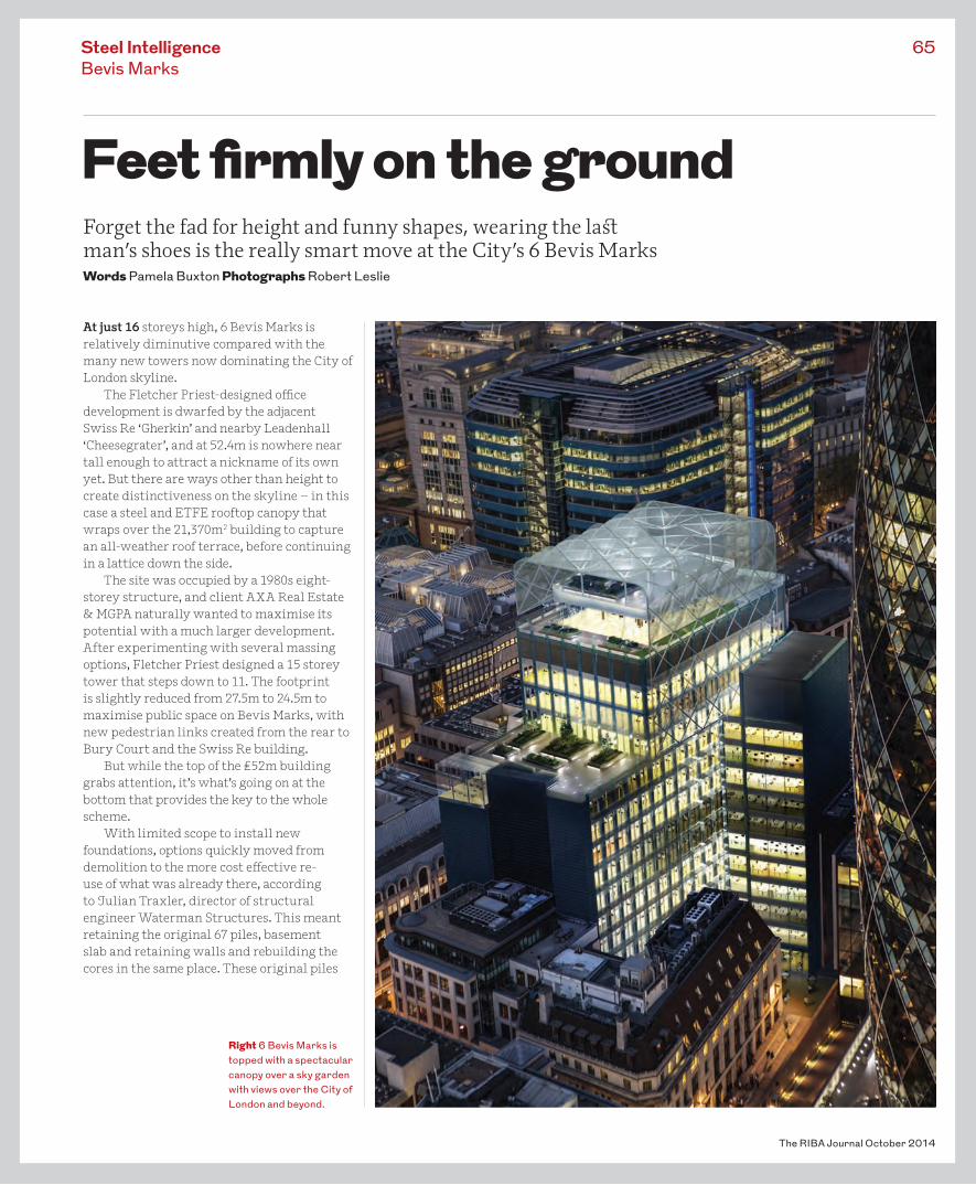
Right 6 Bevis Marks is topped with a spectacular canopy over a sky garden with views over the City of London and beyond.
The RIBA Journal October 2014
66
CreditsClient AXA Real Estate & MGPAArchitect Fletcher PriestStructural engineer Waterman Building Structures; David Dexter Associates (ETFE roof)General contractor SkanskaSteelwork contractor William Hare (main structure) Billington Structures/Tubecon (ETFE roof)
support 56% of the new building with the rest provided by 37 new piles and 66 mini piles.
To make this solution viable, the new, taller building needed to be as lightweight as possible, using a superstructure far lighter than the one it replaced.
‘This wouldn’t have been possible if it had been a concrete building,’ says Traxler.
The structural design uses a 150mm composite steel and concrete deck slab supported by 600mm deep fabricated composite steel beams with circular and rectangular web penetration for service distribution. The total floor zone is 1100mm deep. These beams were fabricated by steelwork contractor William Hare from three plates welded together to the engineer’s specification to ensure the lightest possible outcome for the job.
According to Traxler, the new steelwork
Left The roof canopy continues down the top of the south elevation as a diagrid.
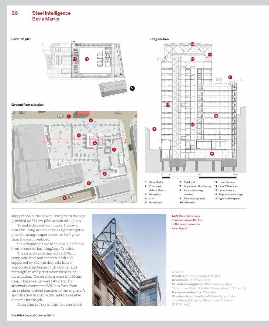
Long section
Ground floor site plan
Level 15 plan
7
8
9
10
11
1213 12
13
14
15
15
Steel IntelligenceBevis Marks
3
2
5
1
6 0 5 25 50m
1 Bevis Marks2 Entrance to 6 Bevis Marks3 Reception4 Lifts5 Bury Court
6 Retail unit7 Upper level of loading bay8 Access to loading bay road9 Plant /storage zone10 Lift shafts
11 Lower terrace12 Level 15 bar area13 Upper terrace14 Polycarbonate canopy15 Typical office space
4
1
for the main structure was relatively straightforward. The structural grid is formed using 13.4 m long secondary beams and 9m primary beams with perimeter columns varying from 300mm circular hollow sections (CHS) to 550mm by 350mm rectangular hollow sections. This gives clear spans across the plan depth with the exception of three CHS columns on every floor excluding reception level.
Floor plates total approximately 1255m2 on levels 1-10 and 650m2 on the smaller levels 11-13. All have 2.75m floor to ceiling heights.
The only major complication was the inclusion of a number of large transfer beams including three at first floor level. The biggest was needed above the loading bay. Weighing 38t, this 15m long beam measures 1500mm deep with 1000mm by 100mm flanges and 50mm webs. Because of its size and weight it had to be brought to site in two pieces and welded; then it was installed with the help of kentledge blocks on the ends of the beams to shift the centre of gravity and avoid the core. All this had to be achieved within a very tight programme window as a result of Olympic Games-related road closures.
On level 11, a 10.5m long plated section – again delivered in two pieces – supports the plant unit enclosure.
Two further 9m transfer beams, each weighting 25t, were incorporated over the reception to avoid columns within the entrance space. All these transfer beams were essential for the success of the development.
‘If you don’t have a decent reception or operational loading bay, you can’t let the building,’ explains Traxler.
Aesthetically, a key reference point for the architects was the nearby, HP Berlage-designed Holland House, in particular its vertical emphasis and the way its ribbed green faience appears ‘closed’ when viewed obliquely. Fletcher Priest aimed to reference this through its choice of textured green glass column cladding panels brought forward from the glass facade line. This cladding is interspersed after every two panels of windows to form a strong vertical rhythm down the building.
‘Like Holland House this looks like a closed façade and you get a sense of solidity of the material which goes as you walk past,’ says project architect Mareike Langkitsch.
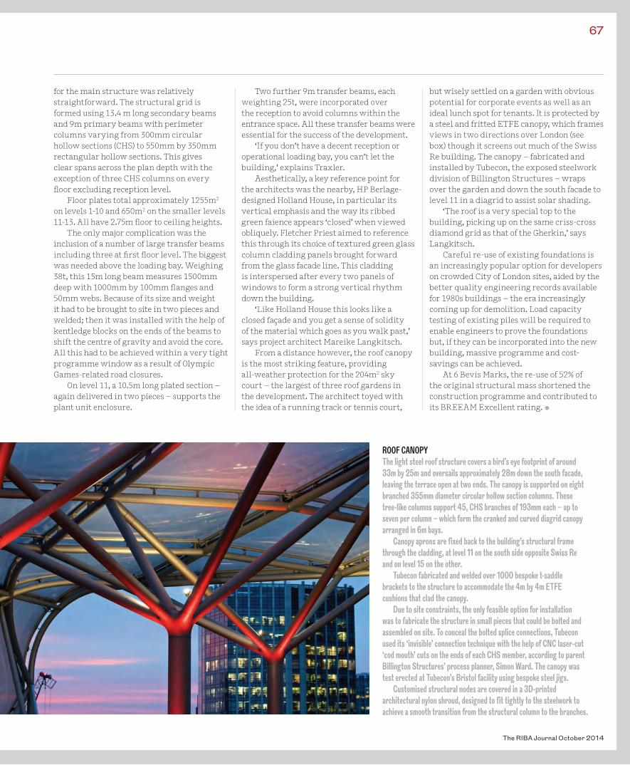
From a distance however, the roof canopy is the most striking feature, providing all-weather protection for the 204m2 sky court – the largest of three roof gardens in the development. The architect toyed with the idea of a running track or tennis court,
but wisely settled on a garden with obvious potential for corporate events as well as an ideal lunch spot for tenants. It is protected by a steel and fritted ETFE canopy, which frames views in two directions over London (see box) though it screens out much of the Swiss Re building. The canopy – fabricated and installed by Tubecon, the exposed steelwork division of Billington Structures – wraps over the garden and down the south facade to level 11 in a diagrid to assist solar shading.
‘The roof is a very special top to the building, picking up on the same criss-cross diamond grid as that of the Gherkin,’ says Langkitsch.
Careful re-use of existing foundations is an increasingly popular option for developers on crowded City of London sites, aided by the better quality engineering records available for 1980s buildings – the era increasingly coming up for demolition. Load capacity testing of existing piles will be required to enable engineers to prove the foundations but, if they can be incorporated into the new building, massive programme and cost-savings can be achieved.
At 6 Bevis Marks, the re-use of 52% of the original structural mass shortened the construction programme and contributed to its BREEAM Excellent rating. •
67
The RIBA Journal October 2014
ROOF CANOPYThe light steel roof structure covers a bird’s eye footprint of around 33m by 25m and oversails approximately 28m down the south facade, leaving the terrace open at two ends. The canopy is supported on eight branched 355mm diameter circular hollow section columns. These tree-like columns support 45, CHS branches of 193mm each – up to seven per column – which form the cranked and curved diagrid canopy arranged in 6m bays.
Canopy aprons are fixed back to the building’s structural frame through the cladding, at level 11 on the south side opposite Swiss Re and on level 15 on the other.
Tubecon fabricated and welded over 1000 bespoke t-saddle brackets to the structure to accommodate the 4m by 4m ETFE cushions that clad the canopy.
Due to site constraints, the only feasible option for installation was to fabricate the structure in small pieces that could be bolted and assembled on site. To conceal the bolted splice connections, Tubecon used its ‘invisible’ connection technique with the help of CNC laser-cut ‘cod mouth’ cuts on the ends of each CHS member, according to parent Billington Structures’ process planner, Simon Ward. The canopy was test erected at Tubecon’s Bristol facility using bespoke steel jigs.
Customised structural nodes are covered in a 3D-printed architectural nylon shroud, designed to fit tightly to the steelwork to achieve a smooth transition from the structural column to the branches.
I once thought that the best buildings occurred in the middle of a Venn diagram between architecture and engineering. But these disciplines are actually more like separate paths weaving back and forth, with something special happening at the intersections. Hunstanton [now Smithdon] School (1949-54) is one such example.
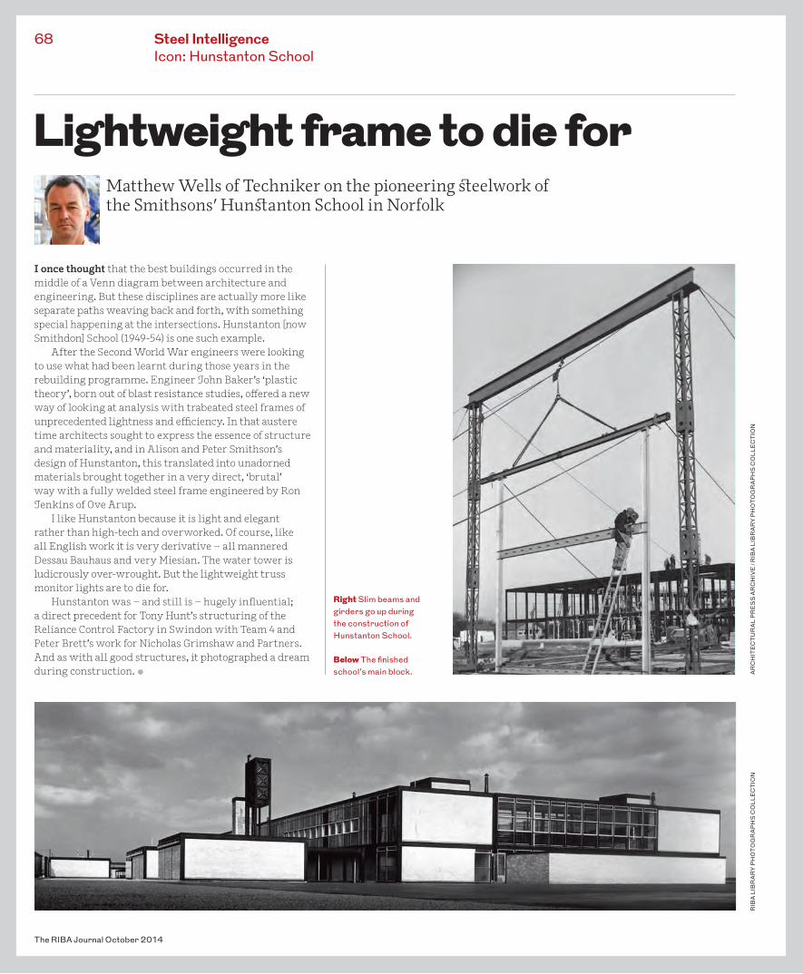
After the Second World War engineers were looking to use what had been learnt during those years in the rebuilding programme. Engineer John Baker’s ‘plastic theory’, born out of blast resistance studies, offered a new way of looking at analysis with trabeated steel frames of unprecedented lightness and efficiency. In that austere time architects sought to express the essence of structure and materiality, and in Alison and Peter Smithson’s design of Hunstanton, this translated into unadorned materials brought together in a very direct, ‘brutal’ way with a fully welded steel frame engineered by Ron Jenkins of Ove Arup.
I like Hunstanton because it is light and elegant rather than high-tech and overworked. Of course, like all English work it is very derivative – all mannered Dessau Bauhaus and very Miesian. The water tower is ludicrously over-wrought. But the lightweight truss monitor lights are to die for.
Hunstanton was – and still is – hugely influential; a direct precedent for Tony Hunt’s structuring of the Reliance Control Factory in Swindon with Team 4 and Peter Brett’s work for Nicholas Grimshaw and Partners. And as with all good structures, it photographed a dream during construction. •
The RIBA Journal October 2014
68 Steel IntelligenceIcon: Hunstanton School
RIB
A LI
BR
AR
Y P
HO
TOG
RA
PH
S C
OLL
EC
TIO
NA
RC
HIT
EC
TU
RA
L P
RE
SS
AR
CH
IVE
/ R
IBA
LIB
RA
RY
PH
OTO
GR
AP
HS
CO
LLE
CT
ION
Lightweight frame to die forMatthew Wells of Techniker on the pioneering steelwork of the Smithsons’ Hunstanton School in Norfolk
Right Slim beams and girders go up during the construction of Hunstanton School.
Below The finished school’s main block.