Embed Size (px)
DESCRIPTION
Steel Plants Fuels and Water Consumption
Citation preview
7/17/2019 Steel Plants Fuels and Water Consumption
http://slidepdf.com/reader/full/steel-plants-fuels-and-water-consumption 1/102
6.1 Fuels, Combustion and Heat FlowAny substance capable of producing heat by combustion may be termed a fuel. However, it is cus-tomary to rank as fuels only those which include carbon and hydrogen and their compounds. Woodwas the earliest fuel used by man. Coal was known to exist in the fourth century B.C., and petro-leum was used by the Persians in the days of Alexander. Prehistoric records of China and Japanare said to contain references to the use of natural gas for lighting and heating.
Heat generated by the combustion of fuel is utilized in industry directly as heat or is converted intomechanical or electrical energy. Fuel has become the major source of energy for manufacturingenterprises.
Fuel enters significantly into manufacturing costs, and in some industries represents one of thelargest items of expense. The steel industry is one of the major consumers of metallurgical coaland also consumes large quantities of electricity, natural gas and petroleum.
Energy conservation efforts and technological improvements have combined to decrease domesticsteel industry energy consumption from 34.40 gigajoules per net tonne (29.58 million Btu/ton) of shipments in 1980 to 24.44 gigajoules per net tonne (21.02 million Btu/ton) of shipments in 1995per AISI survey data. The actual total steel industry average has dropped to an even lower valuebecause most of the non-surveyed companies are electric arc furnace based, which inherently con-sume fewer gigajoules per net tonne (Btu/ton).
6.1.1 Classif icat ion of Fuels There are four general classes of fuels; namely, fossil, byproduct, chemical and nuclear. Of theseclasses, the first three listed achieve energy release by combustion of carbon and/or hydrogen withan oxidant, usually oxygen; the process involves electron exchange to form products of a lowerenergy state and results in an energy release in an exothermic reaction. The fourth class liberatesenergy by fission of the nucleus of the atom and converting mass into energy.
Fossil fuels are hydrocarbon or polynuclear aromatic compounds composed principally of carbonand hydrogen and are derived from fossil remains of plant and animal life. These fossil remainshave been transformed by biochemical and geological metamorphoses into such fuels as coal, nat-ural gas, petroleum, etc.
Chapt er 6St eel Plant Fuels and W aterRequirementsA. Lehrman, Development Engineer, LTV Steel Co.C. D. Bl umenschein, Senior Vice President, Chester EngineersD. J. Doran, Manager of Market Development, Metals, Nalco Chemical Co.
S. E. Stewar t, District Account Manager, Nalco Chemical Co.
C opyright © 1999, The A IS E S teel Foundation, Pittsburgh, PA . A ll rights reserved. 279
7/17/2019 Steel Plants Fuels and Water Consumption
http://slidepdf.com/reader/full/steel-plants-fuels-and-water-consumption 2/102
Byproduct and waste fuels are derived from a main product and are of a secondary nature.Examples of these fuels are coke breeze, coke-oven gas, blast-furnace gas, wood wastes, etc.
Chemical fuels are primarily of an exotic nature and normally are not used in conventionalprocesses. Examples of these fuels are ammonium nitrate and fluorine.
Nuclear fuels are obtained from fissionable materials. The three basic fissionable materials are
uranium–235, uranium–233 and plutonium–239.
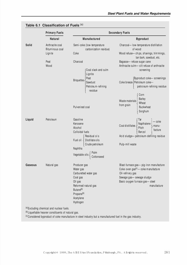
Fossil and byproduct fuels currently used in the steel industry are classified further into three gen-eral divisions; namely, solid, liquid and gaseous fuels. Fuels in each general division can be clas-sified further as natural, manufactured or byproduct. Fuels found in nature sometimes are calledprimary fuels; those manufactured for a specific purpose or market, together with those that arethe unavoidable byproduct of some regular manufacturing process, are called secondary fuels. Theprimary fuels serve as the principal raw materials for the secondary fuels. Table 6.1 gives a classi-fied list of the important fossil fuels. It also lists some interesting byproduct fuels, many of whichhave been utilized by industry to conserve primary fuel.
6.1.1.1Impor tance of Each Class
Coal is the major fuel of public utilities for the generation of power and is essential to the steelindustry for the manufacture of coke.
Coal has been supplanted almost entirely by liquid fuels for the generation of motive power by rail-roads in North America. However, coal continues as a major raw material for many chemical plantsas a source of carbon, hydrogen, and their compounds.
The growth of petroleum consumption has resumed after the price shocks of the past two decadesdue to the increasing demand for its distillation products. Gasoline, the most important product, isused as a motor fuel. Diesel engine fuel is a distillate of crude oil. Distillate and residual fuel oils,and some crude petroleums of too low commercial value for distillation are used for industrial and
domestic heating. Crude and refined petroleum of various grades are used for lubrication of alltypes of machinery and prime movers. Petroleum and natural gas are raw materials for the petro-chemical industry.
Natural gas has replaced coal to a considerable extent for domestic and industrial heating due tothe installation of very large pipelines from producing to consuming centers, the relative level inthe price of natural gas over the intervening time, and its convenience, cleanliness, controllabilityand versatility as a fuel. The byproduct gaseous fuels—coke-oven gas and blast furnace gas—aremajor integrated steel industry fuels.
The nuclear energy industry has fallen on hard times. The development of a practical method forfission of the atom and the release of nuclear energy in controlled chain reactions had given rise
to a different type of power generation system. Many large reactors were built throughout the coun-try and are still in operation. However, no new units are under construction or are being designed.Nuclear power will contribute an ever decreasing share of power to the electric grid as units aretaken out of service unless some major breakthrough in design and operation occurs.
6.1.2 Pr inciples of CombustionFossil and byproduct fuels consist essentially of one, or a mixture of two or more, or of four com-bustible constituents: (1) solid carbon, (2) hydrocarbons, (3) carbon monoxide, and (4) hydrogen.In addition to these combustible constituents, nearly all commercial fuels contain inert material,such as ash, nitrogen, carbon dioxide, and water. Bituminous coal is an example of a fuel which
contains all four of the combustible constituents named above, and coke is an example of a fuelcontaining only one (solid carbon). The constituents which make up liquid fuels and many coalsare quite complex, but because these complex constituents decompose or volatilize into the four
Ironmaking Volume
280 C opyright © 1999, The A IS E S teel Foundation, Pittsburgh, PA . A ll rights reserved.
7/17/2019 Steel Plants Fuels and Water Consumption
http://slidepdf.com/reader/full/steel-plants-fuels-and-water-consumption 3/102
Steel Plant Fuels and Water Requirements
C opyright © 1999, The A IS E S teel Foundation, Pittsburgh, PA . A ll rights reserved. 281
Table 6.1 Classification of Fuels (a)
Primary Fuels Secondary Fuels
Natural Manufactured Byproduct
Solid Anthracite coal Semi- coke (low- temperature Charcoal— low- temperature disti llationBituminous coal carbonization residue) of wood
Lignite Coke Wood refuse— chips, shavings, trimmings,
tan bark, sawdust, etc.
Peat Charcoal Bagasse— refuse sugar cane
Wood Anthracite culm— silt refuse of anthracite
Coal slack and culm screening
Lignite
BriquettesPeat Byproduct coke— screenings
Sawdust Coke breeze Petroleum coke—
Petroleum-refining petroleum-refining residue
residue
Corn
BarleyWaste materials
Wheatfrom grain
Pulverized coal Buckwheat
Sorghum
TarLiquid Petroleum Gasoline — coke
Kerosene Napthalenemanu-Coal di stillates
Alcohol Pitchfacture
Colloidal fuels Benzol
Residual oils Acid sludge— petroleum-defining residue
Fuel o il D is ti l late o il sCrude petroleum Pulp-mil l waste
Naphtha
PalmVegetable oil s
Cottonseed
Gaseous Natural gas Producer gas Blast- furnace gas— pig- iron manufacture
Water gas Coke-oven gas(c) — coke m anufactu re
Carburetted water gas Oil- refinery gas
Coal gas Sewage gas— sewage sludge
Oil gas Basic oxygen furnace gas— steel
Reformed natural gas manufactureButane(b)
Propane(b)
Acetylene
Hydrogen
(a)Excluding chemical and nuclear fuels.(b) Liquefiable heavier constituents of natural gas.(c)Considered byproduct of coke manufacture in steel industry but a manufactured fuel in the gas industry.
7/17/2019 Steel Plants Fuels and Water Consumption
http://slidepdf.com/reader/full/steel-plants-fuels-and-water-consumption 4/102
simpler constituents named above before actual combustion takes place, a knowledge of the com-bustion characteristics of these constituents is sufficient for nearly all practical applications. All of these four constituents of fuels except carbon are gases at the temperatures where combustionoccurs. Combustion takes place by combining oxygen, a gas present in air, with the combustibleconstituents of a fuel. The complete combustion of all fuels generates gases. It is apparent, there-fore, that a review of the properties, thermal values and chemical reactions of gases is necessary
for an understanding of any class of fuel.
Because fuels are used to develop heat, a knowledge of heat terms and the principles of heat floware also essential for the efficient utilization of this heat. The combustion of fuels involves, besidescombustion reactions, the factors and principles which influence speed of combustion, ignitiontemperature, flame luminosity, flame development, flame temperature and limits of flammability. The ensuing divisions of this section deal generally with these subjects. Sections 6.2, 6.3 and 6.4,respectively, deal specifically with the combustion of solid, liquid and gaseous fuels.
6.1.2.1 Units f or M easuri ng Heat
Heat is a form of energy and is measured in absolute joules in SI units.
In the centimetre-gram-second (cgs) the unit for measuring heat was the calorie (abbreviated cal),defined as the amount of heat required to raise the temperature of one gram of pure, air-free water1°C in the temperature interval of 3.5° to 4.5°C at normal atmospheric pressure: this unit was thegram-calorie or small calorie, identified in the Table 6.2 as cal4°C. The temperature interval chosenfor this definition was selected because the density and, therefore, the heat capacity of water variesslightly with temperature and the temperature of maximum density of water is very nearly 4°C. Alarger heat unit in the cgs system was the kilocalorie (kilogram-calorie or large calorie), equal to1000 gram-calories and abbreviated kcal.
Other values for the calorie were obtained by selecting other temperature intervals, resulting, forexample, in the call5°C and the cal20°C listed in Table 6.2. Yet another variation was the mean calo-
rie (abbreviated calmean), defined as 1/100 of the amount of heat required to raise the temperatureof one gram of water from 0°C (the ice point) to 100°C (the boiling point).
None of the foregoing definitions of the calorie were completely satisfactory because of the vari-ation of the heat capacity of water with temperature. Consequently, on the recommendation of theNinth International Conference of Weights and Measures (Paris, 1948), the calorie came to bedefined in energy units in ways that made its value independent of temperature. The thermochem-ical calorie (abbreviated calthermochem) was defined first in international electrical-energy units andlater (1948) in terms of mechanical-energy units. The calorie used in the present International Tables, identified as calIT was adopted in 1956 at the International Conference on Properties of Steam in Paris, and is expressed in mechanical-energy units.
As stated above, the SI unit used to define the calorie in terms of mechanical-energy units is theabsolute joule: the word “absolute” differentiates the SI joule based on mechanical-energy unitsfrom the international joule formerly used which was based on international electrical units.
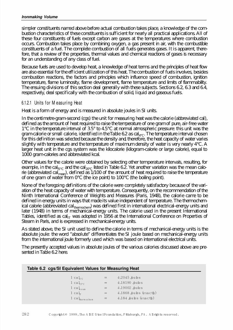
The presently accepted values in absolute joules of the various calories discussed above are pre-sented in Table 6.2 here.
Ironmaking Volume
282 C opyright © 1999, The A IS E S teel Foundation, Pittsburgh, PA . A ll rights reserved.
Table 6.2 cgs/SI Equivalent Values for Measuring Heat
1 cal4°C 4.2045 joules
1 cal15°C 4.18190 joules
1 calm ean 4.19002 joules1 calIT 4.1868 joules (exactly)
1 caltherm ochem 4.184 joules (exactly)
7/17/2019 Steel Plants Fuels and Water Consumption
http://slidepdf.com/reader/full/steel-plants-fuels-and-water-consumption 5/102
In the foot-pound-second (fps) system, the principal unit adopted for measuring heat was theBritish thermal unit (Btu). Defined as the amount of heat required to raise by 1°F the temperatureof one pound of pure, air-free water, its value depended upon the temperature interval chosen forits complete definition. As in the case of the calorie, several values came into use, notably theBtu39°F based on a 1°F rise in temperature at or near the temperature of maximum density of water(39.2°F), the Btu59°F based on the temperature interval of 58.5°F to 59.5°F corresponding nearly to
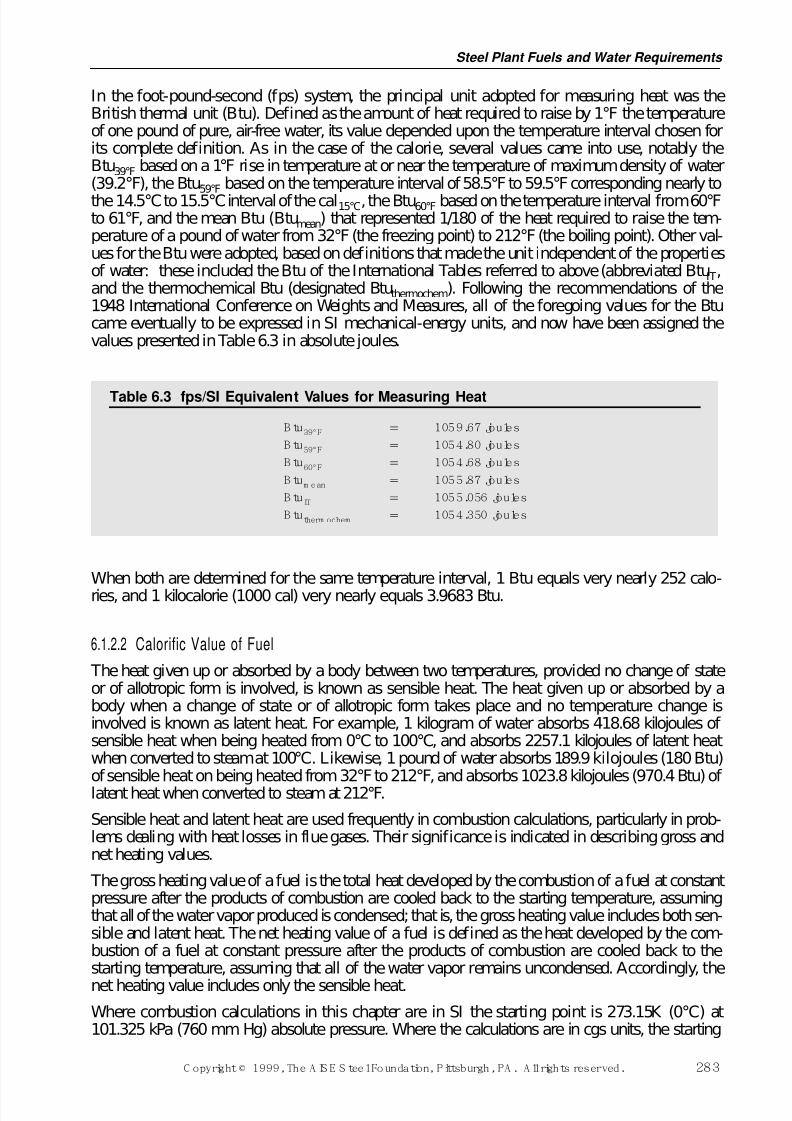
the 14.5°C to 15.5°C interval of the cal15°C, the Btu60°F based on the temperature interval from 60°Fto 61°F, and the mean Btu (Btumean) that represented 1/180 of the heat required to raise the tem-perature of a pound of water from 32°F (the freezing point) to 212°F (the boiling point). Other val-ues for the Btu were adopted, based on definitions that made the unit independent of the propertiesof water: these included the Btu of the International Tables referred to above (abbreviated BtuIT,and the thermochemical Btu (designated Btuthermochem). Following the recommendations of the1948 International Conference on Weights and Measures, all of the foregoing values for the Btucame eventually to be expressed in SI mechanical-energy units, and now have been assigned thevalues presented in Table 6.3 in absolute joules.
When both are determined for the same temperature interval, 1 Btu equals very nearly 252 calo-ries, and 1 kilocalorie (1000 cal) very nearly equals 3.9683 Btu.
6.1.2.2 Calorific Value of Fuel
The heat given up or absorbed by a body between two temperatures, provided no change of stateor of allotropic form is involved, is known as sensible heat. The heat given up or absorbed by abody when a change of state or of allotropic form takes place and no temperature change isinvolved is known as latent heat. For example, 1 kilogram of water absorbs 418.68 kilojoules of sensible heat when being heated from 0°C to 100°C, and absorbs 2257.1 kilojoules of latent heatwhen converted to steam at 100°C. Likewise, 1 pound of water absorbs 189.9 kilojoules (180 Btu)of sensible heat on being heated from 32°F to 212°F, and absorbs 1023.8 kilojoules (970.4 Btu) of latent heat when converted to steam at 212°F.
Sensible heat and latent heat are used frequently in combustion calculations, particularly in prob-lems dealing with heat losses in flue gases. Their significance is indicated in describing gross andnet heating values.
The gross heating value of a fuel is the total heat developed by the combustion of a fuel at constantpressure after the products of combustion are cooled back to the starting temperature, assumingthat all of the water vapor produced is condensed; that is, the gross heating value includes both sen-sible and latent heat. The net heating value of a fuel is defined as the heat developed by the com-bustion of a fuel at constant pressure after the products of combustion are cooled back to thestarting temperature, assuming that all of the water vapor remains uncondensed. Accordingly, the
net heating value includes only the sensible heat.
Where combustion calculations in this chapter are in SI the starting point is 273.15K (0°C) at101.325 kPa (760 mm Hg) absolute pressure. Where the calculations are in cgs units, the starting
Table 6.3 fps/SI Equivalent Values for Measuring Heat
B tu39°F 1059.67 joules
B tu59°F 1054.80 joules
B tu60°F 1054.68 joules
B tum ean 1055.87 joules
B tuIT 1055.056 joules
B tutherm ochem 1054.350 joules
Steel Plant Fuels and Water Requirements
C opyright © 1999, The A IS E S teel Foundation, Pittsburgh, PA . A ll rights reserved. 283
7/17/2019 Steel Plants Fuels and Water Consumption
http://slidepdf.com/reader/full/steel-plants-fuels-and-water-consumption 6/102
point is 0°C at 760 mm absolute pressure. The starting point for calculations in the fps system inthis chapter has been taken as 60°F at 30 in. of Hg absolute pressure; this has generally been thebase for combustion calculations in the American steel industry.
When a fuel contains neither hydrogen nor hydrocarbons, no water vapor is produced by combus-tion and the gross and net heating value will be the same, as in the case of burning carbon or car-
bon monoxide. The heating value or calorific value of a fuel may be determined on a dry or wetbasis. The determination may be made by laboratory tests employing calorimeters, or by calcula-tion. The process of determining the calorific value of solid and liquid fuels by a calorimeter con-sists in completely oxidizing the fuel in a space enclosed by a metal jacket (called the bomb) soimmersed that the heat evolved is absorbed by a weighed portion of water contained in an insulatedvessel. From the rise in temperature of the water, the heat liberated by one gram of the fuel is cal-culated. The best types of calorimeters for solid and liquid fuels are those called oxygen-bombcalorimeters in which the fuel is burned in the presence of compressed oxygen. Gas calorimetersare of different construction to permit volumetric measurement of the gas and its complete com-bustion under non-explosive conditions, as well as absorption of the heat produced in a water jacket.
A saturated gas is one which contains the maximum amount of water vapor it can hold without anycondensation of water taking place. The usual basis for reporting the calorific value of a saturatedfuel gas in SI units is in gross kilojoules per cubic metre measured at 273K and 101 kPa absolutepressure. In the cgs system, calorific value usually has been reported in gross kilocalories per cubicmetre measured at 0°C and 760 mm Hg absolute pressure. In fps units in the American steel indus-try, calorific value usually has been reported in gross Btu per cubic foot of saturated gas measuredat 60°F and 30 in. Hg absolute pressure.
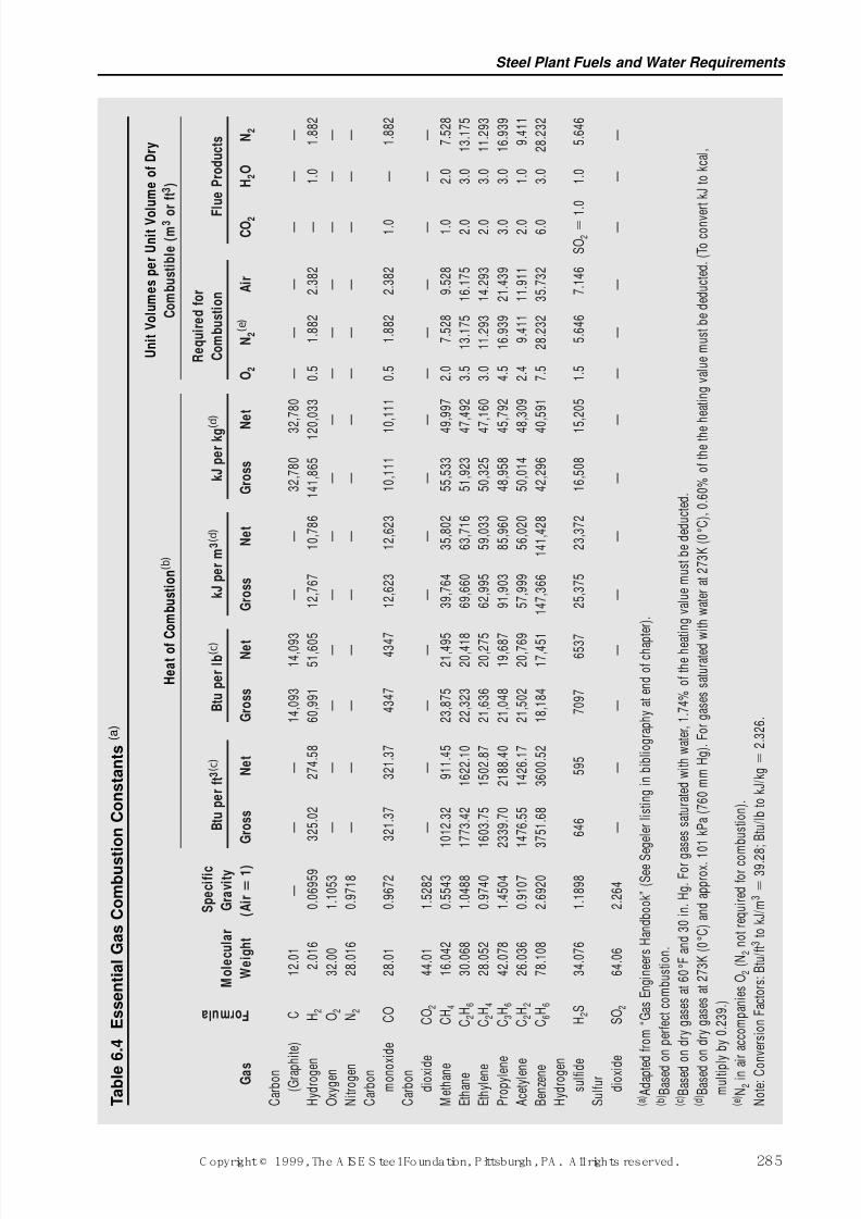
The heating value of a given fuel can be obtained by multiplying the calorific value of each gas byits percentage of the total fuel volume, and then totaling the individual values of the separate con-stituents. The heat of combustion for various dry elementary gases may be found in Table 6.4. Forinstance, the gross heating value of dry blast-furnace gas is 3633 kilojoules per cubic metre (92.5Btu per cubic foot) for the composition used in the following calculations.
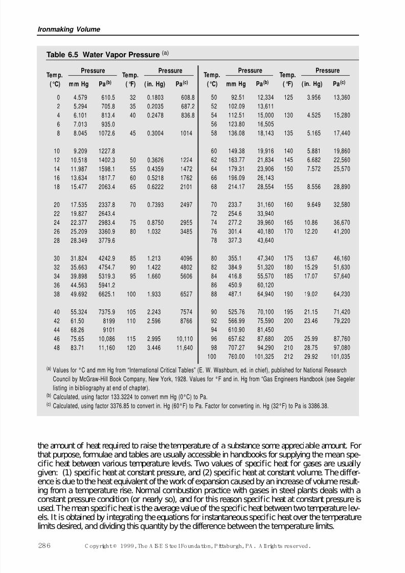
In the calculation of the heating value of gases saturated with water vapor, the volume of watervapor must be deducted from the unit volume of the gas. For instance, a cubic metre of dry carbonmonoxide gas has a heating value of 12,623 kilojoules, but when saturated with water vapor at273K (0°C) and 101 kPa (760 mm Hg), a cubic metre has a heating value of only 12,405 kilojoules(see Table 6.4). Likewise, a cubic foot of dry carbon monoxide gas has a heating value of 321.4Btu, but when saturated with water vapor at 60°F and 30 in. Hg absolute pressure, a cubic foot hasa heating value of only 315.8 Btu. The amount of water vapor present in saturated mixtures can becalculated from data in Table 6.5, as discussed in Section 6.1.2.4.
6.1.2.3 Thermal Capacity, Heat Capacity and Specific Heat The thermal capacity or heat capacity of a substance is expressed as the amount of heat requiredto raise the temperature of a unit weight of the substance one degree in temperature. In SI, it isexpressed in joules per kilogram Kelvin (J /kg K). The fps system has used Btu per pound perdegree Fahrenheit (Btu/lbm °F), while the cgs system has used calories per gram per degree Celsius(cal/g °C). The specific heat is always a ratio, expressed as a number; for example, the specific heatof wrought iron is 0.115. There is no further designation, as this means that if it takes a certainnumber of joules to heat a certain number of kilograms of water a certain number of Kelvins, itwill take only 0.115 times as many joules to heat the same number of kilograms of wrought ironthe same number of Kelvins, and the same figure, 0.115, obviously applies if the centimetre-gram-second or foot-pound-second system were used.
The amount of heat required to raise the temperature of equal masses of different substances to thesame temperature level varies greatly; that is to say, the specific heat varies greatly; also the spe-cific heat of the same substance varies at different temperatures. Usually, it is necessary to know
Ironmaking Volume
284 C opyright © 1999, The A IS E S teel Foundation, Pittsburgh, PA . A ll rights reserved.
7/17/2019 Steel Plants Fuels and Water Consumption
http://slidepdf.com/reader/full/steel-plants-fuels-and-water-consumption 7/102
Steel Plant Fuels and Water Requirements
C opyright © 1999, The A IS E S teel Foundation, Pittsburgh, PA . A ll rights reserved. 285
T a b l e
6 . 4
E s s e n t i a l G a s C o m b u s t i o n C o n s t a n t s ( a )
U n
i t V o
l u m e s p e r
U n
i t V o
l u m e o
f D r y
H e a
t o f
C o m
b u s
t i o n
( b )
C o m
b u s
t i b l e ( m 3 o
r f t 3 )
R e q u
i r e d f o r
S p e c
i f i c
B t u p e r
f t 3 ( c )
B t u p e r
l b ( c )
k J p e r m
3 ( d )
k J p e r
k g (
d )
C o m
b u s
t i o n
F
l u e
P r o
d u c
t s
M o
l e c u
l a r
G r a v
i t y
G a s
W e
i g h t
( A i r
1 )
G r o s s
N e
t
G r o s s
N e t
G r o s s
N e
t
G r o s s
N
e t
O 2
N 2
( e )
A i r
C O
2
H 2
O
N 2
C a r b o n
( G r a p
h i t e )
C
1 2 . 0
1
—
—
—
1 4 , 0
9 3
1 4 , 0 9
3
—
—
3 2 , 7
8 0
3 2 , 7
8 0
—
—
—
—
—
—
H y d r o g e
n
H 2
2 . 0
1 6
0 . 0
6 9 5 9
3 2 5 . 0
2
2 7 4 . 5
8
6 0 , 9
9 1
5 1 , 6 0
5
1 2 , 7
6 7
1 0 , 7
8 6
1 4 1 , 8
6 5
1 2 0
, 0 3 3
0 . 5
1 . 8
8 2
2 . 3
8 2
—
1 . 0
1 . 8
8 2
O x y g e n
O 2
3 2 . 0
0
1 . 1
0 5 3
—
—
—
—
—
—
—
—
—
—
—
—
—
—
N i t r o g e n
N 2
2 8 . 0
1 6
0 . 9
7 1 8
—
—
—
—
—
—
—
—
—
—
—
—
—
—
C a r b o n
m o n o
x i d e
C O
2 8 . 0
1
0 . 9
6 7 2
3 2 1 . 3
7
3 2 1 . 3
7
4 3 4 7
4 3 4
7
1 2 , 6
2 3
1 2 , 6
2 3
1 0 , 1
1 1
1 0 , 1
1 1
0 . 5
1 . 8
8 2
2 . 3
8 2
1 . 0
—
1 . 8
8 2
C a r b o n
d i o x i d e
C O 2
4 4 . 0
1
1 . 5
2 8 2
—
—
—
—
—
—
—
—
—
—
—
—
—
—
M e t h a n e
C H 4
1 6 . 0
4 2
0 . 5
5 4 3
1 0 1 2 . 3
2
9 1 1 . 4
5
2 3 , 8
7 5
2 1 , 4 9
5
3 9 , 7
6 4
3 5 , 8
0 2
5 5 , 5
3 3
4 9 , 9
9 7
2 . 0
7 . 5
2 8
9 . 5
2 8
1 . 0
2 . 0
7 . 5
2 8
E t h a n e
C 2
H 6
3 0 . 0
6 8
1 . 0
4 8 8
1 7 7 3 . 4
2
1 6 2 2 . 1
0
2 2 , 3
2 3
2 0 , 4 1
8
6 9 , 6
6 0
6 3 , 7
1 6
5 1 , 9
2 3
4 7 , 4
9 2
3 . 5
1 3 . 1
7 5
1 6 . 1
7 5
2 . 0
3 . 0
1 3 . 1
7 5
E t h y l e n e
C 2
H 4
2 8 . 0
5 2
0 . 9
7 4 0
1 6 0 3 . 7
5
1 5 0 2 . 8
7
2 1 , 6
3 6
2 0 , 2 7
5
6 2 , 9
9 5
5 9 , 0
3 3
5 0 , 3
2 5
4 7 , 1
6 0
3 . 0
1 1 . 2
9 3
1 4 . 2
9 3
2 . 0
3 . 0
1 1 . 2
9 3
P r o p y l e n e
C 3
H 6
4 2 . 0
7 8
1 . 4
5 0 4
2 3 3 9 . 7
0
2 1 8 8 . 4
0
2 1 , 0
4 8
1 9 , 6 8
7
9 1 , 9
0 3
8 5 , 9
6 0
4 8 , 9
5 8
4 5 , 7
9 2
4 . 5
1 6 . 9
3 9
2 1 . 4
3 9
3 . 0
3 . 0
1 6 . 9
3 9
A c e t y l e n
e
C 2
H 2
2 6 . 0
3 6
0 . 9
1 0 7
1 4 7 6 . 5
5
1 4 2 6 . 1
7
2 1 , 5
0 2
2 0 , 7 6
9
5 7 , 9
9 9
5 6 , 0
2 0
5 0 , 0
1 4
4 8 , 3
0 9
2 . 4
9 . 4
1 1
1 1 . 9
1 1
2 . 0
1 . 0
9 . 4
1 1
B e n z e n e
C 6
H 6
7 8 . 1
0 8
2 . 6
9 2 0
3 7 5 1 . 6
8
3 6 0 0 . 5
2
1 8 , 1
8 4
1 7 , 4 5
1
1 4 7 , 3
6 6
1 4 1 , 4
2 8
4 2 , 2
9 6
4 0 , 5
9 1
7 . 5
2 8 . 2
3 2
3 5 . 7
3 2
6 . 0
3 . 0
2 8 . 2
3 2
H y d r o g e
n
s u l f i d
e
H 2
S
3 4 . 0
7 6
1 . 1
8 9 8
6 4 6
5 9 5
7 0 9 7
6 5 3 7
2 5 , 3
7 5
2 3 , 3
7 2
1 6 , 5
0 8
1 5 , 2
0 5
1 . 5
5 . 6
4 6
7 . 1
4 6
S O 2 1
. 0
1 . 0
5 . 6
4 6
S u l f u r
d i o x i d e
S O 2
6 4 . 0
6
2 . 2
6 4
—
—
—
—
—
—
—
—
—
—
—
—
—
—
( a ) A d a p t e d f r o m
“ G a s E n g i n e e r s H a n d b o o k ” ( S e e S e g e l e r l i s t i n g i n b i b l i o g r a p h y a t e n d o f c h a p
t e r ) .
( b ) B a s e d
o n p e r f e c t c o m b u s t i o n .
( c ) B a s e d
o n d r y g a s e s a t 6 0 ° F a n d 3 0 i n .
H g .
F o r g a s e s s a t u r a t e d w i t h w a t e r , 1 . 7
4 % o
f t h e h e a
t i n g v a l u e m u s t b e d e d u c t e d .
( d ) B a s e d
o n d r y g a s e s a t 2 7 3 K ( 0 ° C ) a n d a p p r o x . 1
0 1 k P a ( 7 6 0 m m H g ) . F o r g a s e s s a t u r a t e d w i t h w a t e r a t 2 7 3 K ( 0 ° C ) , 0 . 6
0 % o
f t h e t h e
h e a t i n g v a l u e m u s t b e d e d u c t e d .
( T o c o n v e
r t k J t o k c a l ,
m u l t i p
l y b y 0 . 2
3 9 . )
( e ) N
2 i n a i r a c c o m p a n i e s O 2
( N 2 n o t r e q u i r e d f o r c o m b u s t i o n ) .
N o t e : C o
n v e r s i o n F a c t o r s : B t u / f t 3 t o k J / m 3
3 9 . 2 8 ; B t u / l b t o k J / k g
2 . 3
2 6 .
F o r m u l a
7/17/2019 Steel Plants Fuels and Water Consumption
http://slidepdf.com/reader/full/steel-plants-fuels-and-water-consumption 8/102
the amount of heat required to raise the temperature of a substance some appreciable amount. Forthat purpose, formulae and tables are usually accessible in handbooks for supplying the mean spe-cific heat between various temperature levels. Two values of specific heat for gases are usuallygiven: (1) specific heat at constant pressure, and (2) specific heat at constant volume. The differ-ence is due to the heat equivalent of the work of expansion caused by an increase of volume result-ing from a temperature rise. Normal combustion practice with gases in steel plants deals with a
constant pressure condition (or nearly so), and for this reason specific heat at constant pressure isused. The mean specific heat is the average value of the specific heat between two temperature lev-els. It is obtained by integrating the equations for instantaneous specific heat over the temperaturelimits desired, and dividing this quantity by the difference between the temperature limits.
Ironmaking Volume
286 C opyright © 1999, The A IS E S teel Foundation, Pittsburgh, PA . A ll rights reserved.
Table 6.5 Water Vapor Pressure (a)
Pressure PressureTemp. Temp.
(°C) mm Hg Pa(b) ( °F) ( in. Hg) Pa(c)
0 4.579 610.5 32 0.1803 608.82 5.294 705.8 35 0.2035 687.2
4 6.101 813.4 40 0.2478 836.8
6 7.013 935.0
8 8.045 1072.6 45 0.3004 1014
10 9.209 1227.8
12 10.518 1402.3 50 0.3626 1224
14 11.987 1598.1 55 0.4359 1472
16 13.634 1817.7 60 0.5218 1762
18 15.477 2063.4 65 0.6222 2101
20 17.535 2337.8 70 0.7393 2497
22 19.827 2643.4
24 22.377 2983.4 75 0.8750 2955
26 25.209 3360.9 80 1.032 3485
28 28.349 3779.6
30 31.824 4242.9 85 1.213 4096
32 35.663 4754.7 90 1.422 4802
34 39.898 5319.3 95 1.660 5606
36 44.563 5941.2
38 49.692 6625.1 100 1.933 6527
40 55.324 7375.9 105 2.243 7574
42 61.50 8199 110 2.596 8766
44 68.26 9101
46 75.65 10,086 115 2.995 10,110
48 83.71 11,160 120 3.446 11,640
(a) Values for °C and mm Hg from “International Critical Tables” (E. W. Washburn, ed. in chief), published for National Research
Council by McGraw-Hill Book Company, New York, 1928. Values for °F and in. Hg from “Gas Engineers Handbook (see Segeler
listing in bi bliography at end of chapter).(b) Calculated, using factor 133.3224 to convert mm Hg (0°C) to Pa.(c) Calculated, using factor 3376.85 to convert in. Hg (60°F) to Pa. Factor for converting in. Hg (32°F) to Pa is 3386.38.
Pressure PressureTemp. Temp.
(°C) mm Hg Pa(b) ( °F) ( in. Hg) Pa(c)
50 92.51 12,334 125 3.956 13,36052 102.09 13,611
54 112.51 15,000 130 4.525 15,280
56 123.80 16,505
58 136.08 18,143 135 5.165 17,440
60 149.38 19,916 140 5.881 19,860
62 163.77 21,834 145 6.682 22,560
64 179.31 23,906 150 7.572 25,570
66 196.09 26,143
68 214.17 28,554 155 8.556 28,890
70 233.7 31,160 160 9.649 32,580
72 254.6 33,940
74 277.2 39,960 165 10.86 36,670
76 301.4 40,180 170 12.20 41,200
78 327.3 43,640
80 355.1 47,340 175 13.67 46,160
82 384.9 51,320 180 15.29 51,630
84 416.8 55,570 185 17.07 57,640
86 450.9 60,120
88 487.1 64,940 190 19.02 64,230
90 525.76 70,100 195 21.15 71,420
92 566.99 75,590 200 23.46 79,220
94 610.90 81,450
96 657.62 87,680 205 25.99 87,760
98 707.27 94,290 210 28.75 97,080
100 760.00 101,325 212 29.92 101,035
7/17/2019 Steel Plants Fuels and Water Consumption
http://slidepdf.com/reader/full/steel-plants-fuels-and-water-consumption 9/102
The heat content is the heat contained at a specified temperature above some fixed temperature. Itis calculated by multiplying the weight of a substance by the mean specific heat times the temper-ature difference, or Ht weight mean specific heat (T2 – T1). For convenience in calculationswith gases, the unit weight of the volume of a cubic metre or a cubic foot of gas is often used.
6.1.2.4 Gas Law s
Calculations based on the gas laws to be discussed involve the concepts of absolute zero andabsolute temperature. Absolute zero in SI is 0K, in the cgs system it is –273.15°C and in the fpssystem it is –459.67°F: for practical purposes to facilitate calculations, –273°C and –460°F can betaken as absolute zero in the cgs and fps systems, respectively.
Absolute temperature in SI is the temperature expressed in Kelvins above 0K at an absolute pres-sure of 101.325 kPa (one standard atmosphere). In the cgs system, absolute temperature (°Cabs) hasbeen the temperature in degrees Celsius (formerly called degrees centigrade) above –273.15°C at760 mm Hg (millimetres of mercury) at one standard atmosphere absolute pressure. Absolute tem-perature in the cgs system also has been expressed according to the Kelvin scale of temperature,using K instead of °C, (1°C 1K). Absolute zero on the Kelvin scale is 0K, and on the Celsiusscale absolute zero, as stated above, is –273.15°C. Temperatures on the Kelvin and Celsius scaleshave the following relation:
TK T°C 273.15
or, to facilitate calculations,
TK T°C 273 (6.1.1)
Absolute temperature in the fps system is the temperature in degrees Fahrenheit (°Fabs) above459.67°F at 29.921 inches of mercury (one standard atmosphere) absolute pressure. Also in the fpssystem, absolute temperatures have been expressed according to the Rankine temperature scale,
using degrees Rankine (°R) instead of degrees Fahrenheit (°F), (1°R 1°F). Absolute zero on theRankine scale is 0°R, and on the Fahrenheit scale absolute zero, as stated above, is –459.67°F. Temperatures on these two scales have the following relation:
T°R T°F 459.67
or, to facilitate calculations,
T°R T°F 460 (6.1.2)
Again to facilitate calculations, rounded values for an absolute pressure of one atmosphere (101kPA in SI and 30 in. Hg in the fps system) can be used instead of the more precise values in thedefinitions.
The volume of an ideal gas varies in direct proportion to its absolute temperature (Charles’ Law)and inversely as its absolute pressure (Boyle’s Law).
For example, in SI units, the volume of 1000 m3 of a gas measured at 288K (15°C) and 101 kPaabsolute pressure, when heated to 1253K (980°C) and 101 kPa absolute pressure, is equal to:
1000 1253/288 4351 m3
and the volume of 1000 m3 of fuel gas measured at 288K(15°C) and 101 kPa absolute pressure isequal to 802 m3 when compressed to 25 kPa gauge pressure at 288K, calculated as follows:
1000 101/(10125) 802 m3
Similarly, in the fps system, the volume of 40,000 ft3 of gas measured at 60°F and 30 in. Hgabsolute pressure, when heated to 1800°F and 30 in. Hg absolute pressure, is equal to:
40,000 (460 1800)/(46060) 174,000 ft3
Steel Plant Fuels and Water Requirements
C opyright © 1999, The A IS E S teel Foundation, Pittsburgh, PA . A ll rights reserved. 287
7/17/2019 Steel Plants Fuels and Water Consumption
http://slidepdf.com/reader/full/steel-plants-fuels-and-water-consumption 10/102
and the volume of 40,000 ft3 of fuel gas measured at 60°F and 30 in. Hg (standard conditions) isequal to 31,579 ft3 when compressed to 8 in. Hg gauge pressure at 60°F, calculated as follows:
40,000 30/(308) 31,579 ft3
The total pressure of any gas mixture is equal to the sum of the pressures of each component. Each
component produces a partial pressure proportional to its concentration in the mixture. Therefore,in a mixture of water vapor and any other gas, each exerts a pressure proportional to its percentageby volume, and since water has a definite vapor pressure at various temperatures, as shown in Table6.5, the concentration of water vapor in a gas is limited. When this limit of water vapor is reached,the gas is said to be saturated. Any drop in temperature or increase in pressure from that point willcause condensation of some of the water vapor; for instance, the water vapor in 1000 m3 of satu-rated fuel gas at 293K (20°C) and 101 kPa would equal:
1000 2.3378/100 23.1 m3
(2.3378 kPa is the partial pressure of water vapor in a saturated mixture at 293K (20°C) and 101kPa as shown in Table 6.5.) In fps units, water vapor in 1000 ft3 of saturated fuel gas measured at
60°F and 30 in. Hg is calculated as follows:1000 0.522/30 17.40 ft3
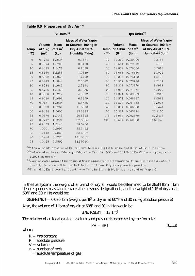
(0.522 is the partial pressure of water vapor in a saturated mixture at 60°F and 30 in. Hg, from Table 6.5.) The amount of water vapor which will condense at various temperatures may be ascer-tained by the use of Table 6.6.
In some combustion calculations, it is necessary to convert volumes to weights and vice versa.Such conversions can be made very conveniently by using molar units; namely, the mole (abbrevi-ated mol and expressed in kilograms) in SI; the gram-mole (abbreviated g-mol and expressed ingrams) in the cgs system; and the pound-mole (abbreviated lb-mol and expressed in pounds) in thefps system. A mol, g-mol or lb-mol of a substance is that quantity whose mass expressed in the
proper units stated above is the same number as the number of the molecular weight. Thus, the mol-ecular weight of oxygen is 32, so that the mol in SI is 32 kg of oxygen, the g-mol in the cgs sys-tem is 32 grams of oxygen, and the lb-mol in the fps system is 32 lb of oxygen.
In SI, a mol of any gas (its molecular weight in kilograms) theoretically occupies 22.414 m3 at273.15K and 101.325 kPa absolute pressure. (Values of 22.4 m3, 273K and 101 kPa are closeenough for most calculations.) In the cgs system, a g-mol of any gas (its molecular weight ingrams) theoretically occupies 22.414 dm3at 0°C and 760 mm Hg absolute pressure. In the fps sys-tem, a lb-mol of any gas (its molecular weight in pounds) theoretically occupies 359 ft3 at 32°Fand 29.921 in. Hg absolute pressure; or, at 60°F and 30 in. Hg absolute pressure (the usual refer-ence points for combustion problems in the steel industry) a lb-mol occupies 378.4 ft3. The sim-plicity of using molar units in combustion calculations is shown by the following examples: Theweight of a cubic metre of dry air is calculated in SI as follows:
0.21 (% vol. of O2 in air) 32 (mol. wt. of 02) 6.720.79 (% vol. of N2 in air) 28 (mol. wt. of N2) 22.12
Weight in kg of a mol of dry air 28.84.
28.84/22.4 1.29 kg (weight per m3 of dry air at 273K and 101 kPa absolute pressure)
The volume of 1 kg of dry air at 273K and 101 kPa absolute pressure is equal to:
22.4/28.84 0.78 m3
In the cgs system, the calculations would be similar to those in SI, except that the weight of a gram-mol of dry air would be determined to be 28.84 grams, and the weight of a cubic decimetre (liter)of dry air would be found to be 1.29 grams: the volume of 1 gram of dry air at 0°C and 760 mmHg would be found to be 0.78 dm3.
Ironmaking Volume
288 C opyright © 1999, The A IS E S teel Foundation, Pittsburgh, PA . A ll rights reserved.
7/17/2019 Steel Plants Fuels and Water Consumption
http://slidepdf.com/reader/full/steel-plants-fuels-and-water-consumption 11/102
In the fps system, the weight of a lb-mol of dry air would be determined to be 28.84 lbm, (lbmdenotes pounds-mass and replaces the previous designation lb) and the weight of 1 ft3of dry air at
60°F and 30 in Hg would be:28.84/378.4 0.076 lbm (weight per ft3 of dry air at 60°F and 30 in. Hg absolute pressure)
Also, the volume of 1 lbm of dry air at 60°F and 30 in. Hg would be
378.4/28.84 13.1 ft3
The relation of an ideal gas to its volume and pressure is expressed by the formula:
PV nRT (6.1.3)where:
R gas constant
P absolute pressureV volumen number of mols
T absolute temperature of gas
Steel Plant Fuels and Water Requirements
C opyright © 1999, The A IS E S teel Foundation, Pittsburgh, PA . A ll rights reserved. 289
Table 6.6 Properties of Dry Air (a)
SI Units(b)
Mass of Water Vapor
Volume Mass to Saturate 100 kg of
Temp. of 1 kg of 1 m3 Dry Air at 100%(°C) (m3) (kg) Humidity(c) (kg)
0 0.7735 1.2928 0.3774
5 0.7874 1.2700 0.5403
10 0.8019 1.2471 0.7638
15 0.8160 1.2255 1.0649
20 0.8302 1.2046 1.4702
25 0.8443 1.1844 2.0082
30 0.8584 1.1649 2.7194
35 0.8726 1.1460 3.6586
40 0.8868 1.1277 4.8872
45 0.9010 1.1099 6.5279
50 0.9151 1.0928 8.6686
55 0.9293 1.0761 11.5070
60 0.9434 1.0600 15.3233
65 0.9576 1.0443 20.5315
70 0.9717 1.0291 27.8395
75 0.9859 1.0143 38.5230
80 1.0001 0.9999 55.1492
85 1.0142 0.9860 83.6207
90 1.0284 0.9724 141.5052
95 1.0425 0.9592 312.9940
(a)A t an ab solute pressure of 101.325 kPa (760 m m H g) in SI units, and 30 in. of H g in fps units.(b)C alculated on basis of density of dry air at 273.15K (0°C ) and 101.325 kP a (760 m m H g) eq ual to
1.2928 kg per m 3.(c)M ass of w ater vapor at low er hum idities is approxim ately proportional to the hum idity; e.g., at 50%
hum idity, the m ass w ill be one-half that at 100% hum idity for a g iven tem perature.(d)From “G as Eng ineers H andbook”(see Segeler listing in bibliograp hy at end of chapter).
fps Units(d)
Mass of Water Vapor
Volume Mass to Saturate 100 lbm
Temp. of 1 lbm of 1 ft3 of Dry Air at 100%(°F) (ft3) (lbm) Humidity(c) (lbm)
32 12.360 0.080906 0.3767
40 12.561 0.079612 0.5155
50 12.812 0.078050 0.7613
60 13.063 0.076550 1.1022
70 13.315 0.075103 1.5726
80 13.567 0.073710 2.2184
90 13.818 0.072370 3.0998
100 14.069 0.071077 4.2979
110 14.321 0.069829 5.0913
120 14.571 0.068627 8.0981
130 14.823 0.067463 11.0935
140 15.074 0.066338 15.2441
150 15.327 0.065244 21.1155
175 15.954 0.062679 52.6416
200 16.584 0.060298 226.384
7/17/2019 Steel Plants Fuels and Water Consumption
http://slidepdf.com/reader/full/steel-plants-fuels-and-water-consumption 12/102
The numerical value of R in the above equation depends upon what units (SI, cgs or fps) are usedto measure P. V, n and T. Values of R for various combinations of units for measuring the otherquantities are as follows:
SI units R 8.3144 kJ/mol K
CGS units R 8.3144 J/g-mol K
R 62.37 mm Hg-dm3/g-mol K R .08206 dm3-atm/g-mol K
FPS units R 10.703 lbf ft3 in2/lb-mol °RR 21.83 in. Hg-ft3/lb-mol °R
In SI units, an example of the use of the foregoing formula would be to calculate the volume occu-pied by 100 kg of natural gas having a composition of 80% CH4, 18% C2H6 and 2% N2 by volumeat a gauge pressure of 27 kPa and a temperature of 38°C (using the data from Table 6.4).
The weight of a mol of the gas is:
CH4 0.80 16 12.8
C2H6 0.18 30 5.4N2 0.02 28 0.56kg18.76 kg
P 27 101 128 kPa absoluten 100/18.76 5.33R 8.3144 T 273 38 311
Substituting these values into the equation 6.1.3 for a perfect gas:
128V 5.33 8.3144 311V 107.7 m3
In fps units, a similar application of the formula would be to calculate the volume occupied by 100lbm of natural gas of the same composition as above at 8 in. Hg gauge pressure and a temperatureof 100°F.
P 30 8 38 in. Hg absoluten 100/18.75 5.33 lb-molsR 21.83 T 460 100 560°R
38V 5.33 21.83 560V 1715 ft3
6.1.2.5 Combusti on Calculat ions
The combustion of fuels is carried out by chemical reaction with air, and occasionally with airenriched with oxygen, or with pure oxygen. Dry air is a mixture of the following gas volumesunder average conditions:
N2 78.03%O2 20.99%Ar 0.94%CO2 0.03%H2 0.01% Total 100.00%
In combustion calculations it is customary to include all elements in dry air (other than oxygen)with the nitrogen, as shown below:
% by Volume % by WeightOxygen 20.99 23.11Nitrogen 79.01 76.89
Ironmaking Volume
290 C opyright © 1999, The A IS E S teel Foundation, Pittsburgh, PA . A ll rights reserved.
7/17/2019 Steel Plants Fuels and Water Consumption
http://slidepdf.com/reader/full/steel-plants-fuels-and-water-consumption 13/102
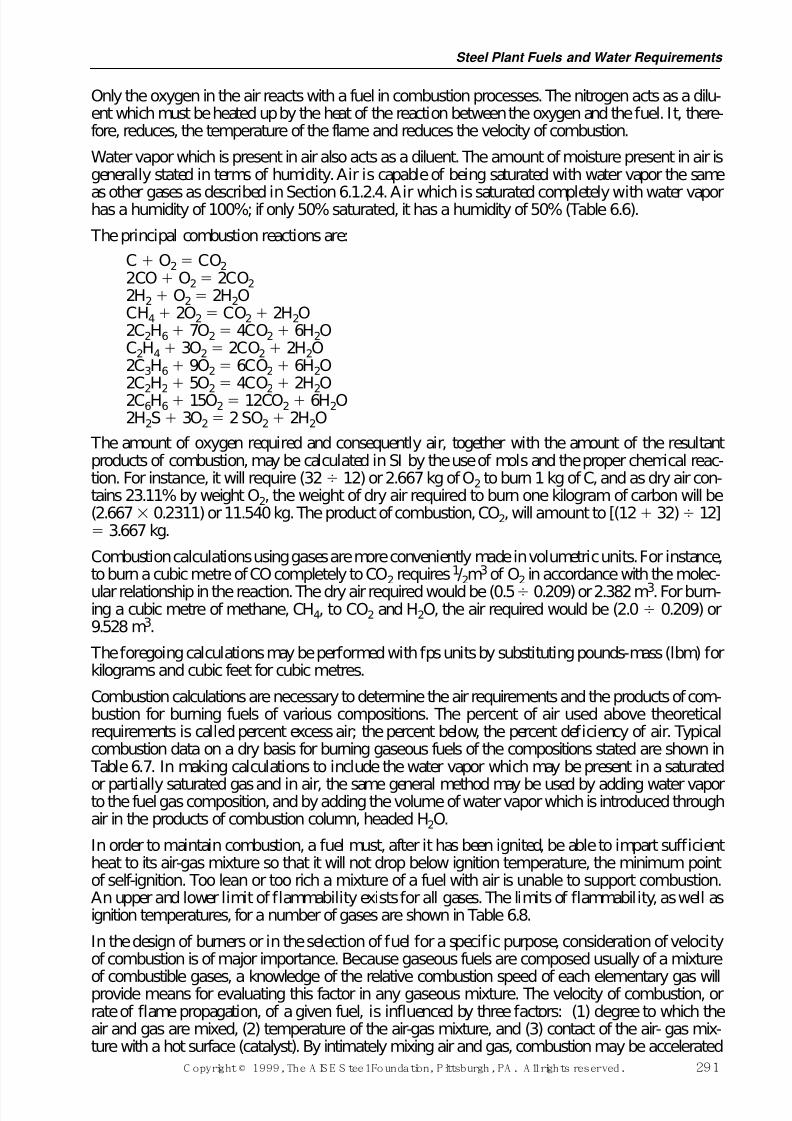
Only the oxygen in the air reacts with a fuel in combustion processes. The nitrogen acts as a dilu-ent which must be heated up by the heat of the reaction between the oxygen and the fuel. It, there-fore, reduces, the temperature of the flame and reduces the velocity of combustion.
Water vapor which is present in air also acts as a diluent. The amount of moisture present in air isgenerally stated in terms of humidity. Air is capable of being saturated with water vapor the same
as other gases as described in Section 6.1.2.4. Air which is saturated completely with water vaporhas a humidity of 100%; if only 50% saturated, it has a humidity of 50% (Table 6.6).
The principal combustion reactions are:
C O2 CO22CO O2 2CO22H2 O2 2H2OCH4 2O2 CO2 2H2O2C2H6 7O2 4CO2 6H2OC2H4 3O2 2CO2 2H2O2C3H6 9O2 6CO2 6H2O2C
2H
2 5O
2 4CO
2 2H
2O
2C6H6 15O2 12CO2 6H2O2H2S 3O2 2 SO2 2H2O
The amount of oxygen required and consequently air, together with the amount of the resultantproducts of combustion, may be calculated in SI by the use of mols and the proper chemical reac-tion. For instance, it will require (32 12) or 2.667 kg of O2 to burn 1 kg of C, and as dry air con-tains 23.11% by weight O2, the weight of dry air required to burn one kilogram of carbon will be(2.667 0.2311) or 11.540 kg. The product of combustion, CO2, will amount to [(12 32) 12] 3.667 kg.
Combustion calculations using gases are more conveniently made in volumetric units. For instance,to burn a cubic metre of CO completely to CO2 requires1/2m
3of O2 in accordance with the molec-
ular relationship in the reaction. The dry air required would be (0.5 0.209) or 2.382 m3. For burn-ing a cubic metre of methane, CH4, to CO2 and H2O, the air required would be (2.0 0.209) or9.528 m3.
The foregoing calculations may be performed with fps units by substituting pounds-mass (lbm) forkilograms and cubic feet for cubic metres.
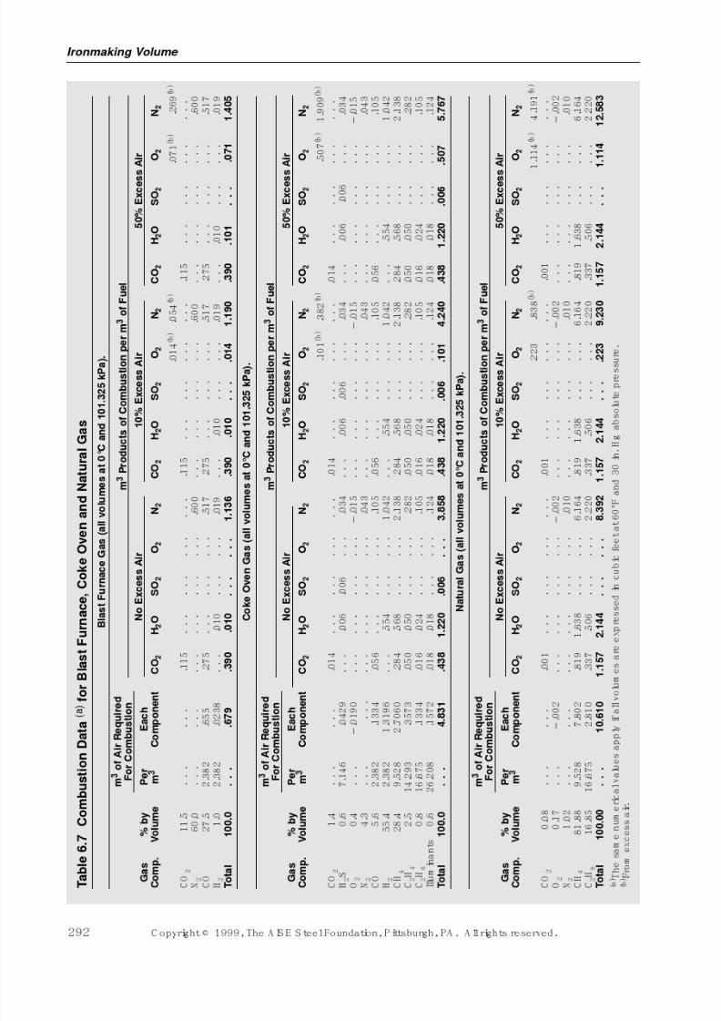
Combustion calculations are necessary to determine the air requirements and the products of com-bustion for burning fuels of various compositions. The percent of air used above theoreticalrequirements is called percent excess air; the percent below, the percent deficiency of air. Typicalcombustion data on a dry basis for burning gaseous fuels of the compositions stated are shown in Table 6.7. In making calculations to include the water vapor which may be present in a saturated
or partially saturated gas and in air, the same general method may be used by adding water vaporto the fuel gas composition, and by adding the volume of water vapor which is introduced throughair in the products of combustion column, headed H2O.
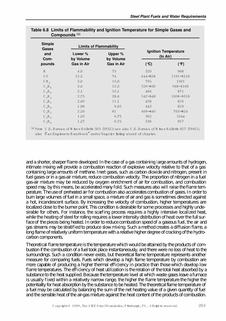
In order to maintain combustion, a fuel must, after it has been ignited, be able to impart sufficientheat to its air-gas mixture so that it will not drop below ignition temperature, the minimum pointof self-ignition. Too lean or too rich a mixture of a fuel with air is unable to support combustion.An upper and lower limit of flammability exists for all gases. The limits of flammability, as well asignition temperatures, for a number of gases are shown in Table 6.8.
In the design of burners or in the selection of fuel for a specific purpose, consideration of velocityof combustion is of major importance. Because gaseous fuels are composed usually of a mixture
of combustible gases, a knowledge of the relative combustion speed of each elementary gas willprovide means for evaluating this factor in any gaseous mixture. The velocity of combustion, orrate of flame propagation, of a given fuel, is influenced by three factors: (1) degree to which theair and gas are mixed, (2) temperature of the air-gas mixture, and (3) contact of the air- gas mix-ture with a hot surface (catalyst). By intimately mixing air and gas, combustion may be accelerated
Steel Plant Fuels and Water Requirements
C opyright © 1999, The A IS E S teel Foundation, Pittsburgh, PA . A ll rights reserved. 291
7/17/2019 Steel Plants Fuels and Water Consumption
http://slidepdf.com/reader/full/steel-plants-fuels-and-water-consumption 14/102
7/17/2019 Steel Plants Fuels and Water Consumption
http://slidepdf.com/reader/full/steel-plants-fuels-and-water-consumption 15/102
and a shorter, sharper flame developed. In the case of a gas containing large amounts of hydrogen,
intimate mixing will provide a combustion reaction of explosive velocity relative to that of a gascontaining large amounts of methane. Inert gases, such as carbon dioxide and nitrogen, present infuel gases or in a gas-air mixture, reduce combustion velocity. The proportion of nitrogen in a fuelgas-air mixture may be reduced by oxygen enrichment of air for combustion, and combustionspeed may, by this means, be accelerated many fold. Such measures also will raise the flame tem-perature. The use of preheated air for combustion also accelerates combustion of gases. In order toburn large volumes of fuel in a small space, a mixture of air and gas is sometimes directed againsta hot, incandescent surface. By increasing the velocity of combustion, higher temperatures arelocalized close to the burner point. This condition is desirable for some processes and highly unde-sirable for others. For instance, the scarfing process requires a highly intensive localized heat,while the heating of steel for rolling requires a lower intensity distribution of heat over the full sur-face of the pieces being heated. In order to reduce combustion speed of a gaseous fuel, the air andgas streams may be stratified to produce slow mixing. Such a method creates a diffusion flame, along flame of relatively uniform temperature with a relative higher degree of cracking of the hydro-carbon components.
Theoretical flame temperature is the temperature which would be attained by the products of com-bustion if the combustion of a fuel took place instantaneously, and there were no loss of heat to thesurroundings. Such a condition never exists, but theoretical flame temperature represents anothermeasure for comparing fuels. Fuels which develop a high flame temperature by combustion aremore capable of producing a higher thermal efficiency in practice than those which develop lowflame temperatures. The efficiency of heat utilization is the relation of the total heat absorbed by asubstance to the heat supplied. Because the temperature level at which waste gases leave a furnace
is usually fixed within a relatively narrow range, the higher the flame temperature the higher thepotentiality for heat absorption by the substance to be heated. The theoretical flame temperature of a fuel may be calculated by balancing the sum of the net heating value of a given quantity of fueland the sensible heat of the air-gas mixture against the heat content of the products of combustion.
Steel Plant Fuels and Water Requirements
C opyright © 1999, The A IS E S teel Foundation, Pittsburgh, PA . A ll rights reserved. 293
Table 6.8 Limits of Flammability and Ignition Temperature for Simple Gases andCompounds (a)
Simple
GasesLimits of Flammability
Ignition Temperatureand Lower % Upper %
(In Air)Com- by Volume by Volume
pounds Gas in Air Gas in Air (°C) (°F)
H 4.0 75 520 968
C O 12.5 74 644–658 1191–1216
C H 4 5.0 15.0 705 1301
C 2H 6 3.0 12.5 520–630 968–1166
C 3H 8 2.1 10.1 466 871
C 2H 4 2.75 28.6 542–548 1008–1018
C 3H 6 2.00 11.1 458 856
C 4H 8 1.98 9.65 443 829
C 2H 2 2.50 81 406–440 763–824C 6H 6 1.35 6.75 562 1044
C 7H 8 1.27 6.75 536 997
(a)From U .S. B ureau of M ines B ulletin 503 (1952); see also U .S. B ureau of M ines B ulletin 627 (1965);
also “G as Engineers H andbook”under Segeler listing at end of chapter.
7/17/2019 Steel Plants Fuels and Water Consumption
http://slidepdf.com/reader/full/steel-plants-fuels-and-water-consumption 16/102
Theoretical flame temperature so calculated should be corrected for dissociation of CO2 and H2Oat temperatures in excess of 1650°C (3000°F). The theoretical flame temperatures for a number of important gaseous fuels are given in Table 6.23 in Section 6.4.5. The reader is referred to the Gas Engineers Handbook and the books by Lewis and von Elbe, by Hougen et al., and Trinks andMawhinney and others listed in the bibliography at the end of this chapter for a full explanation of combustion stoichiometry, fuel economy calculations and the calculation of theoretical flame tem-
peratures, and the dissociation of gases at elevated temperatures.
There are a number of factors which determine the character, size and shape of a gas flame. Gasesburned at very high combustion velocity will produce very little or no luminosity regardless of thekind of gas. The velocity and volume with which the air-gas stream leaves a burner or furnace port,the fuel-air ratio, and the amount of non-combustible material in the fuel will influence the lengthand shape of a flame. The kind of gas to be burned has a very great effect upon the character of theflame. Carbon monoxide and hydrogen burn with an invisible to a clear blue flame, while thehydrocarbon gases, methane, ethane, etc. are capable of developing highly luminous flames. Theprincipal reason that these gases burn with a luminous flame is due to the thermal breakdown of the hydrocarbons into carbon and hydrogen, and under combustion conditions which permit this,
the carbon particles are heated to incandescence thereby giving the flame its luminous appearance. The luminosity of a flame may be decreased or increased by varying the supply of air. A deficiencyof air below theoretical requirements will increase luminosity and it also usually will lengthen theflame. An excess of air will decrease luminosity and shorten the flame with most burners or fur-nace ports. Increasing the temperature of preheat of the air for combustion will reduce luminosity,as is also the case when water vapor (steam), which may be introduced with the gas, air, or foratomization of liquid fuels, is increased. A luminous flame has a number of desirable qualities, theprincipal one being its greater ability to transfer heat by radiation from a fixed temperature level.However, it should be noted that a luminous flame is obtained usually at a lower temperature levelthan when the same fuel is burned with a lower degree of luminosity.
6.1.3 Heat FlowHeat flow is caused by a difference in temperature, and heat is transmitted in three ways, namely,by conduction, by convection, and by radiation
6.1.3.1 Conduction
Conduction is the transmission of heat through a solid body without visible motion of the body, asthrough a steel bar. The amount of heat transferred through a homogeneous solid by conduction isexpressed by the formula:
q (k A T)/ x (6.1.4)
where, in SI, the quantities are expressed in the following units:
q watts transmitted (1 W 1 J/s)k conductivity factor in W/m K A area in m2
T temperature difference in K x length of heat-transfer path in metres
and, in fps units:
q Btu transmitted per hourk conductivity factor in Btu in. / ft2 h °F
A area in square feet T temperature difference in °Fx length of heat-transfer path in inches
Ironmaking Volume
294 C opyright © 1999, The A IS E S teel Foundation, Pittsburgh, PA . A ll rights reserved.
7/17/2019 Steel Plants Fuels and Water Consumption
http://slidepdf.com/reader/full/steel-plants-fuels-and-water-consumption 17/102
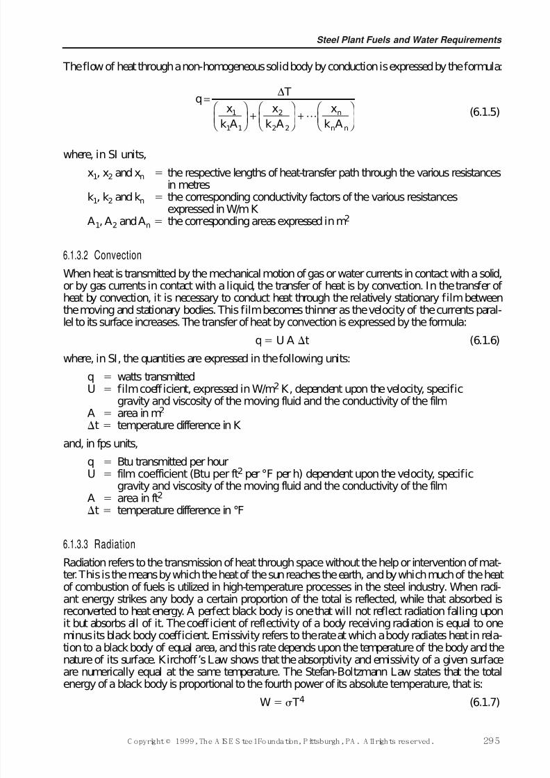
The flow of heat through a non-homogeneous solid body by conduction is expressed by the formula:
(6.1.5)
where, in SI units,
x1, x2 and xn the respective lengths of heat-transfer path through the various resistancesin metres
k1, k2 and kn the corresponding conductivity factors of the various resistancesexpressed in W/m K
A1, A2 and An the corresponding areas expressed in m2
6.1.3.2 Convection
When heat is transmitted by the mechanical motion of gas or water currents in contact with a solid,or by gas currents in contact with a liquid, the transfer of heat is by convection. In the transfer of heat by convection, it is necessary to conduct heat through the relatively stationary film betweenthe moving and stationary bodies. This film becomes thinner as the velocity of the currents paral-lel to its surface increases. The transfer of heat by convection is expressed by the formula:
q U A t (6.1.6)
where, in SI, the quantities are expressed in the following units:
q watts transmittedU film coefficient, expressed in W/m2 K, dependent upon the velocity, specific
gravity and viscosity of the moving fluid and the conductivity of the filmA area in m2
t temperature difference in K
and, in fps units,
q Btu transmitted per hourU film coefficient (Btu per ft2 per °F per h) dependent upon the velocity, specific
gravity and viscosity of the moving fluid and the conductivity of the filmA area in ft2
t temperature difference in °F
6.1.3.3 RadiationRadiation refers to the transmission of heat through space without the help or intervention of mat-ter. This is the means by which the heat of the sun reaches the earth, and by which much of the heatof combustion of fuels is utilized in high-temperature processes in the steel industry. When radi-ant energy strikes any body a certain proportion of the total is reflected, while that absorbed isreconverted to heat energy. A perfect black body is one that will not reflect radiation falling uponit but absorbs all of it. The coefficient of reflectivity of a body receiving radiation is equal to oneminus its black body coefficient. Emissivity refers to the rate at which a body radiates heat in rela-tion to a black body of equal area, and this rate depends upon the temperature of the body and thenature of its surface. Kirchoff’s Law shows that the absorptivity and emissivity of a given surfaceare numerically equal at the same temperature. The Stefan-Boltzmann Law states that the total
energy of a black body is proportional to the fourth power of its absolute temperature, that is:
W T4 (6.1.7)
q T
x
k A
x
k A
x
k An
n n
=
+
+
∆
1
1 1
2
2 2
L
Steel Plant Fuels and Water Requirements
C opyright © 1999, The A IS E S teel Foundation, Pittsburgh, PA . A ll rights reserved. 295
7/17/2019 Steel Plants Fuels and Water Consumption
http://slidepdf.com/reader/full/steel-plants-fuels-and-water-consumption 18/102
where, in SI units, W equals the total emissive power of a black body, expressed in watts per squaremetre (W/m2), is the Stefan-Boltzmann constant equal to 5.71 10–5 ergs/cm2 s K 4 or 5.71 10–8 watts per m2 K 4 and T is the absolute temperature in Kelvins (K).
In fps units, W is expressed in Btu/ft2 h °R4 and equals 0.173 10–8 Btu/ft2 h °R4 with T rep-resenting the absolute temperature in °R.
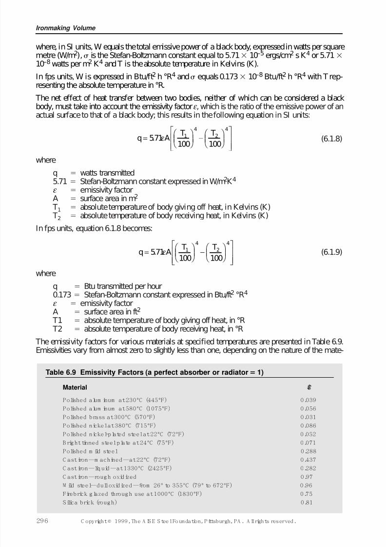
The net effect of heat transfer between two bodies, neither of which can be considered a blackbody, must take into account the emissivity factorε , which is the ratio of the emissive power of anactual surface to that of a black body; this results in the following equation in SI units:
(6.1.8)
where
q watts transmitted5.71 Stefan-Boltzmann constant expressed in W/m2K 4
ε emissivity factorA surface area in m2
T1 absolute temperature of body giving off heat, in Kelvins (K) T2 absolute temperature of body receiving heat, in Kelvins (K)
In fps units, equation 6.1.8 becomes:
(6.1.9)
where
q Btu transmitted per hour0.173 Stefan-Boltzmann constant expressed in Btu/ft2 °R4
ε emissivity factorA surface area in ft2
T1 absolute temperature of body giving off heat, in °R T2 absolute temperature of body receiving heat, in °R
The emissivity factors for various materials at specified temperatures are presented in Table 6.9.Emissivities vary from almost zero to slightly less than one, depending on the nature of the mate-
q A T T
=
−
571100 100
1
4
2
4
. ε
q A T T
=
−
571100 100
1
4
2
4
. ε
Ironmaking Volume
296 C opyright © 1999, The A IS E S teel Foundation, Pittsburgh, PA . A ll rights reserved.
Table 6.9 Emissivity Factors (a perfect absorber or radiator 1)
Material ε
Polished alum inum at 230°C (445°F) 0.039
Polished alum inum at 580°C (1075°F) 0.056
Polished brass at 300°C (570°F) 0.031
Polished nickel at 380°C (715°F) 0.086
Polished nickel-plated steel at 22°C (72°F) 0.052
B right tinned steel plate at 24°C (75°F) 0.071
Polished m ild steel 0.288
C ast iron—m achined—at 22°C (72°F) 0.437
C ast iron—liquid—at 1330°C (2425°F) 0.282
C ast iron—rough oxidized 0.97M ild steel—dull oxidized—from 26° to 355°C (79° to 672°F) 0.96
Firebrick glazed through use at 1000°C (1830°F) 0.75
Silica brick (rough) 0.81
7/17/2019 Steel Plants Fuels and Water Consumption
http://slidepdf.com/reader/full/steel-plants-fuels-and-water-consumption 19/102
rial, its surfaces face finish, and its temperature. Polished metal surfaces have low emissivities,whereas those of oxidized surfaces and non-metals generally approach a value of one. In the gen-eration of heat from fuels, the character of the flame and its proximity to the receptor of heat is par-ticularly signif icant in the transfer of heat by radiation. The amount of heat transferred from aflame varies widely and in proportion to its degree of luminosity. The transfer of heat by radiationvaries inversely with the square of the distance between the transmitter and receptor of radiant
energy. For that reason, flames should be kept close to the substance to be heated where high heattransfer rates are desirable.
6.2 Solid Fuels and Their Ut il izati onSolid fuels have played a significant role in the evolution of our modern, industrial civilization.Coal in particular has been of far-reaching importance in that it has provided the prodigiousamount of energy essential to the development of the iron and steel industries. Vast quantities of this energy source remain to be exploited, but the rate of utilization far exceeds the rate at which
coal is being formed. It follows that the efficient use of the remaining supply is desirable. Towardthis end, modern coal research is directed.
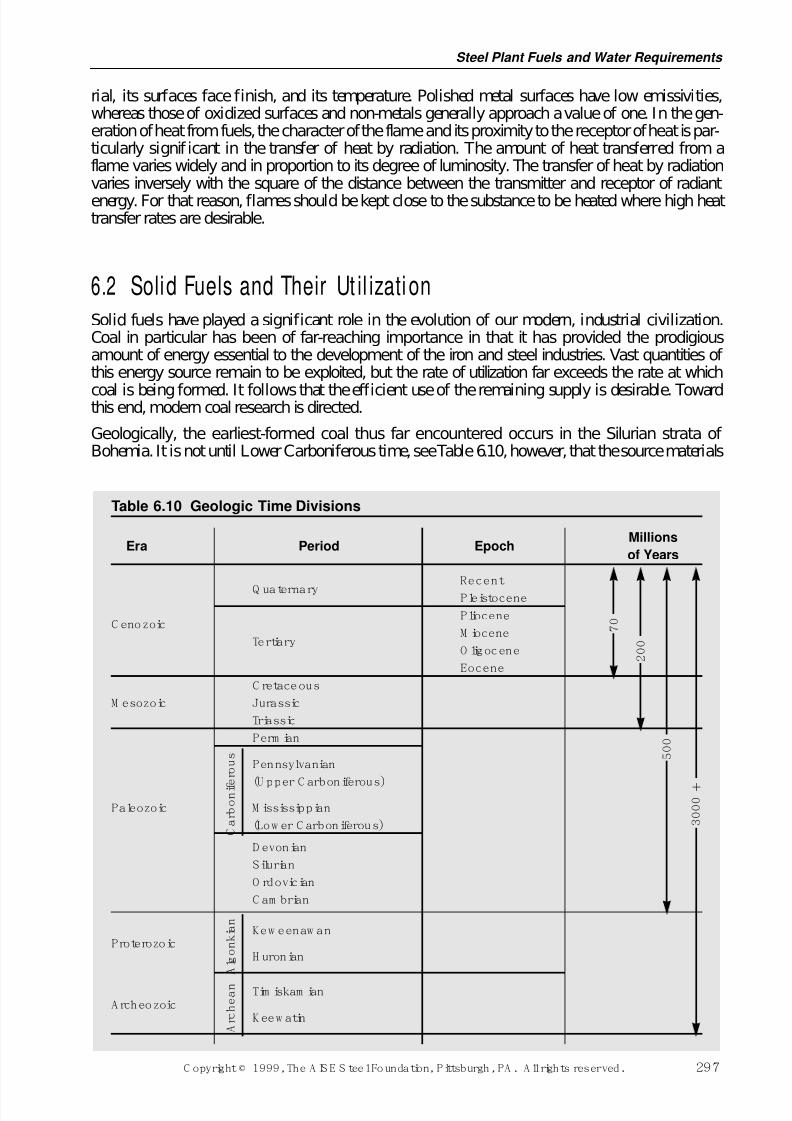
Geologically, the earliest-formed coal thus far encountered occurs in the Silurian strata of Bohemia. It is not until Lower Carboniferous time, see Table 6.10, however, that the source materials
Steel Plant Fuels and Water Requirements
C opyright © 1999, The A IS E S teel Foundation, Pittsburgh, PA . A ll rights reserved. 297
Table 6.10 Geologic Time Divisions
MillionsEra Period Epoch
of Years
RecentQ uaternary Pleistocene
PlioceneC enozoic
M ioceneTertiary
O ligocene
Eocene
C retaceous
M esozoic Jurassic
Triassic
Perm ian
Pennsylvanian
(U pper C arboniferous)
Paleozoic M ississippian
(Low er C arboniferous)
D evonian
Silurian
O rdovician
C am brian
Kew eenaw anProterozoic
H uronian
Tim iskam ianA rcheozoic
K eew atin
C a r b o n i f e r o u s
7 0
2 0 0
5 0 0
3 0 0 0
A l g o n
k i a n
A r c
h e a n
7/17/2019 Steel Plants Fuels and Water Consumption
http://slidepdf.com/reader/full/steel-plants-fuels-and-water-consumption 20/102
of coal began to accumulate in significant quantities. Every continent, including Antarctica, con-tains some coal and no system of rocks younger than the Silurian is devoid of this important sub-stance. In North America major concentrations of source materials were accumulated during theCarboniferous, Cretaceous and Tertiary periods. A similar statement can be made for Europe but,in contrast, some of the most important Asiatic coals occur in Triassic and Jurassic rocks of theMesozoic Era.
6.2.1 Coal Resources The known coal deposits in the U.S. are greater than those of any other country. Based on 1995International Energy Annual data, the U.S. identified recoverable coal reserves of all ranks wereestimated to be 246 billion metric tons (272 billion short tons) which is approximately 24% of theknown world reserves. This figure represents coal of all ranks in the ground at depths and bedthicknesses generally considered mineable under current economic conditions. This would beenough to supply requirements for a long period in the future if all present coal reserves were avail-able economically and of acceptable quality. A considerable quantity of the reserves of better qual-
ity coking coal has been utilized in the past and it is apparent that in the future it will be necessaryto use coals requiring efficient extraction, cleaning, and other processing to assure proper utiliza-tion.
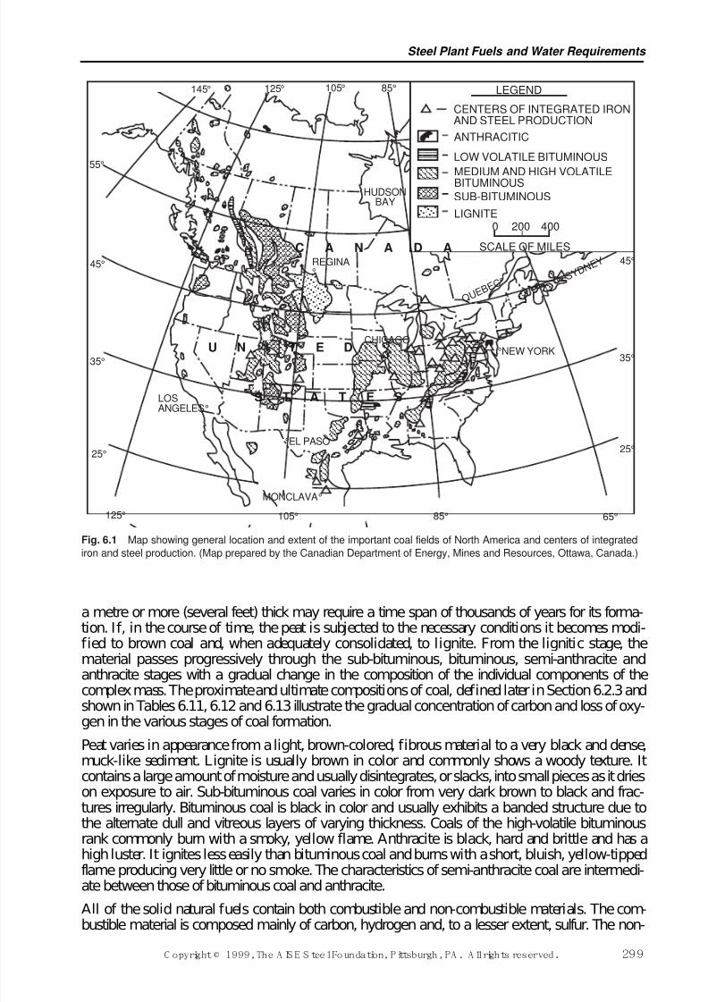
For obvious reasons, the steel industry has been striving to use coals which would produce metal-lurgical coke of optimum quality with a minimum of processing. Concentrations of coals of thisclass are found chiefly in the Appalachian area, although isolated deposits also exist in someCentral and Western states. The preponderance of total coal reserve in the U.S. is in the form of lower-rank coals in the Great Plains, the Rocky Mountains, the Pacific Coast states and the Gulf region, see Fig. 6.1. These western coals are taking a larger share of the electric utility market dueto lower sulfur content and lower mining costs. As a result, the eastern share of national produc-tion fell to 53% in 1995 from the 93% level in 1970. Total domestic coal production is still increas-
ing and reached 937 million metric tons (1,033 million short tons) in 1995.
6.2.1.1 Origin and Composition of Coal
Coal is known to be a complex mixture of plant substances which have been altered in varyingdegrees by physical and chemical processes. Ordinarily, plant material, upon death, completelydecomposes because of the action of microorganisms. Under certain circumstances, notably thoseassociated with forested fresh-water swamps, this action is inhibited by antibiotic solutions whichare common in this type of environment. As a result, the rate of accumulation of the plant mater-ial exceeds that of its decomposition and dispersion. Under such conditions a brown fibrousdeposit known as peat is formed. Peat is the first step in the formation of coal.
Peat deposits, formed millions of years ago, subsequently were submerged through vertical move-ments of the earth’s crust, in which position they became covered by deposits of sedimentary rocks.Later movements of the earth’s crust raised many of these deposits to various heights above sealevel. In the meantime, the peat had been changed, through agencies of biological action, pressure,and heat, into coal. The better ranks of coal in this country were formed during the Carboniferousperiod, the geologic period when conditions were most favorable for plant accumulation anddecomposition. Included in the present deposits that originated in that period are the coal fields of the Appalachian and Central states.
The rate at which peat forms depends upon the rapidity of plant growth and the manner in whichtissue increment is related to the rate of decomposition. It has been estimated that approximately
one century is required to form a deposit of mature, compacted peat about one-third metre (onefoot) in thickness. Certain studies of volatile matter relationships suggest that about a one-metrethick (a three-foot-thick) deposit of mature peat is required to produce a one-third-metre thick(one-foot-thick) layer of bituminous coal. These and other data indicate that a coal seam which is
Ironmaking Volume
298 C opyright © 1999, The A IS E S teel Foundation, Pittsburgh, PA . A ll rights reserved.
7/17/2019 Steel Plants Fuels and Water Consumption
http://slidepdf.com/reader/full/steel-plants-fuels-and-water-consumption 21/102
a metre or more (several feet) thick may require a time span of thousands of years for its forma-tion. If, in the course of time, the peat is subjected to the necessary conditions it becomes modi-fied to brown coal and, when adequately consolidated, to lignite. From the lignitic stage, thematerial passes progressively through the sub-bituminous, bituminous, semi-anthracite andanthracite stages with a gradual change in the composition of the individual components of thecomplex mass. The proximate and ultimate compositions of coal, defined later in Section 6.2.3 and
shown in Tables 6.11, 6.12 and 6.13 illustrate the gradual concentration of carbon and loss of oxy-gen in the various stages of coal formation.
Peat varies in appearance from a light, brown-colored, fibrous material to a very black and dense,muck-like sediment. Lignite is usually brown in color and commonly shows a woody texture. Itcontains a large amount of moisture and usually disintegrates, or slacks, into small pieces as it drieson exposure to air. Sub-bituminous coal varies in color from very dark brown to black and frac-tures irregularly. Bituminous coal is black in color and usually exhibits a banded structure due tothe alternate dull and vitreous layers of varying thickness. Coals of the high-volatile bituminousrank commonly burn with a smoky, yellow flame. Anthracite is black, hard and brittle and has ahigh luster. It ignites less easily than bituminous coal and burns with a short, bluish, yellow-tippedflame producing very little or no smoke. The characteristics of semi-anthracite coal are intermedi-ate between those of bituminous coal and anthracite.
All of the solid natural fuels contain both combustible and non-combustible materials. The com-bustible material is composed mainly of carbon, hydrogen and, to a lesser extent, sulfur. The non-
Steel Plant Fuels and Water Requirements
C opyright © 1999, The A IS E S teel Foundation, Pittsburgh, PA . A ll rights reserved. 299
LEGEND
CENTERS OF INTEGRATED IRONAND STEEL PRODUCTION
ANTHRACITIC
LOW VOLATILE BITUMINOUS
MEDIUM AND HIGH VOLATILEBITUMINOUS
SUB-BITUMINOUS
LIGNITE0 200 400
SCALE OF MILES
Q U E B
E C °
45°
35°
65°
25°
85°105°125°
25°
35°
45°
55°
145° 125° 105° 85°
C A N A D A
HUDSONBAY
LOSANGELES°
REGINA° S Y
D N E Y
CHICAGO
°
MONCLAVA°
°EL PASO
U N I T E D
S T A T E S
°NEW YORK
Fig. 6.1 Map showing general location and extent of the important coal fields of North America and centers of integrated
iron and steel production. (Map prepared by the Canadian Department of Energy, Mines and Resources, Ottawa, Canada.)
7/17/2019 Steel Plants Fuels and Water Consumption
http://slidepdf.com/reader/full/steel-plants-fuels-and-water-consumption 22/102
combustible constituents are water, nitrogen and oxygen, and a variety of mineral materials usuallyreferred to as ash.
The bituminous coals are of greatest interest to the steel industry in view of the fact that essentially
all coking coals fall in this category. The lustrous black bands which are conspicuous in a lump of bituminous coal are generally referred to as vitrain although some American coal petrographersemploy the term anthraxylon in preference. Following U.S. Bureau of Mines terminology, theanthraxylon is derived from woody plant tissues and is surrounded by a dull ground mass made upof translucent attritus, opaque attritus and fusain. The attrital portion is composed of finely com-minuted fragments of altered plant materials. Fusain is a friable, charcoal-like substance derivedfrom woody tissues and is a term used universally without modification.
In addition to the readily recognizable bands of vitrain and fusain, European and Asiatic coal inves-tigators have found it useful to identify silky, minutely striated layers within a coal as clarain.Layers of dull, compact coal are called durain. Thus, coal seams can be thought of as being com-posed, usually, of various mixtures of vitrain, fusain, clarain and durain, each occurring in the formof layers which are visually observable. Coals made up largely of vitrain and clarain are spoken of as bright coals whereas coals containing a high percentage of durain are called splint coals. Brightcoals are generally better coking coals than splint coals, vitrain apparently playing an importantpart in the carbonization process. Fusain will not coke, but in small percentages it may actuallyincrease coke strength provided the particle size is fine enough. The fixed carbon content is higherand the volatile matter content is lower in fusain than in the other banded ingredients.
Microscopic study has shown the banded components to be composed of identifiable plant entitiescalled phyterals, but of greater significance is the fact that the vitrain, fusain, clarain and durainare made up of numerous components or macerals which can be defined by their physical andchemical properties. Durain, for example, may include several macerals (vitrinite, semi-fusinite,
micrinite, cutinite, etc.) which are easily distinguished by their differing optical properties.Additional information regarding the nature and variability of these individual coal componentsand their contribution to the effective and efficient utilization of all types of coal appears in refer-ences on applied coal petrography at the end of this chapter.
Ironmaking Volume
300 C opyright © 1999, The A IS E S teel Foundation, Pittsburgh, PA . A ll rights reserved.
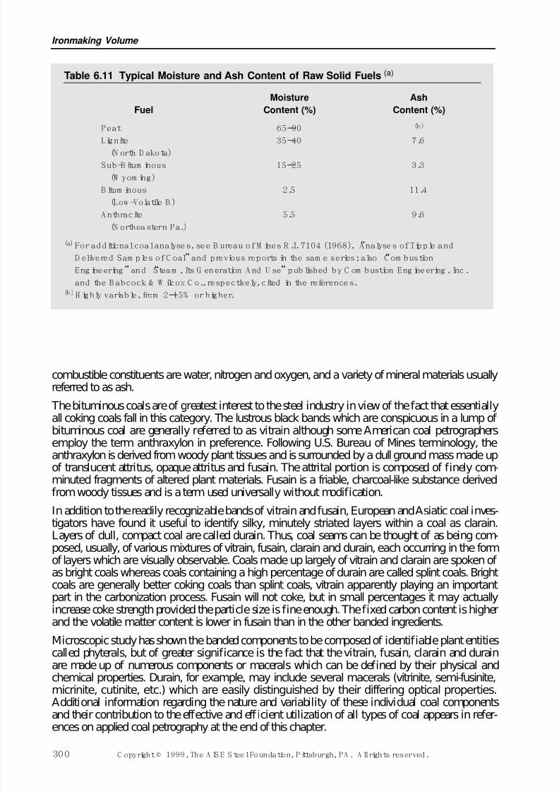
Table 6.11 Typical Moisture and Ash Content of Raw Solid Fuels (a)
Moisture Ash
Fuel Content (%) Content (%)
Peat 65–90 (b)
Lignite 35–40 7.6(N orth D akota)
Sub-B itum inous 15–25 3.3
(W yom ing)
B itum inous 2.5 11.4
(Low -Volatile B )
A nthracite 5.5 9.6
(N ortheastern Pa.)
(a) For additional coal analyses, see B ureau of M ines R .I. 7104 (1968), “Analyses of Tipple and
D elivered Sam ples of C oal”and previous reports in the sam e series; also “C om bustion
Eng ineering”and “Steam , Its G eneration A nd U se”pub lished by C om bustion Eng ineering , Inc.
and the B abcock & W ilcox C o., respectively, cited in the references.(b)H ighly variable, from 2–15% or higher.
7/17/2019 Steel Plants Fuels and Water Consumption
http://slidepdf.com/reader/full/steel-plants-fuels-and-water-consumption 23/102
Steel Plant Fuels and Water Requirements
C opyright © 1999, The A IS E S teel Foundation, Pittsburgh, PA . A ll rights reserved. 301
T a b l e
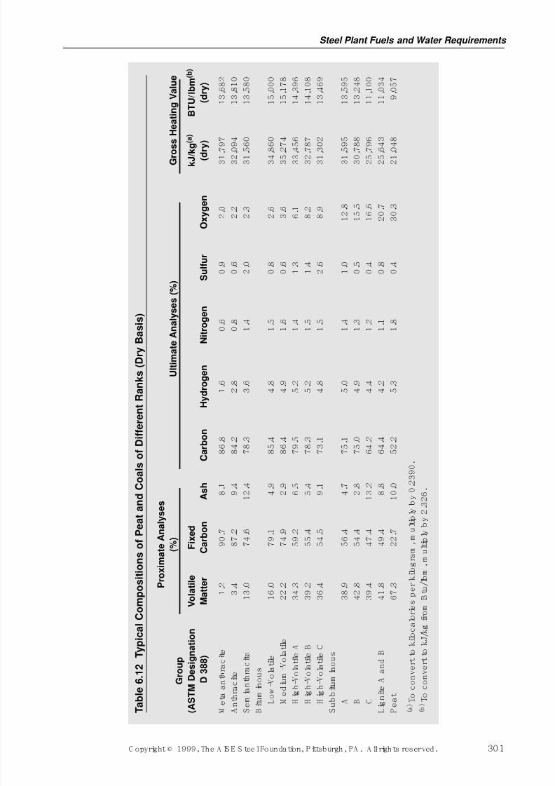
6 . 1 2
T y p i c a l C o m p o s i t i o n s o f P e a t a n d C o a l s o f D i f f e r e n
t R a n k s ( D r y B a s i s )
P r o x i m a t
e A n a l y s e s
(
% )
U l t i m a t e A n a l y s e s ( % )
G r o s s H e a t i n g V a l u e
G r o u p
( A S T M
D e s i g n a t i o n
V o l a t i l e
F i x e d
k J / k g ( a )
B T U / l b m ( b )
D 3 8 8 )
M a t t e r
C
a r b o n
A s h
C a r b o n
H y d r o g e n
N i t r o g e n
S u l f u r
O x y g e n
( d r y )
( d r y )
M e
t a a
n t h r a c
i t e
1 . 2
9 0 . 7
8 . 1
8 6 . 8
1 . 6
0 . 6
0 . 9
2 . 0
3 1 , 7
9 7
1 3 , 6
8 2
A n
t h r a
c i t e
3 . 4
8 7 . 2
9 . 4
8 4 . 2
2 . 8
0 . 8
0 . 6
2 . 2
3 2 , 0
9 4
1 3 , 8
1 0
S e m
i a n
t h r a c
i t e
1 3 . 0
7 4 . 6
1 2 . 4
7 8 . 3
3 . 6
1 . 4
2 . 0
2 . 3
3 1 , 5
6 0
1 3 , 5
8 0
B i t u m i n o u s
L o w - V o
l a t i l e
1 6 . 0
7 9 . 1
4 . 9
8 5 . 4
4 . 8
1 . 5
0 . 8
2 . 6
3 4 , 8
6 0
1 5 , 0
0 0
M e d
i u m - V o
l a t i l e
2 2 . 2
7 4 . 9
2 . 9
8 6 . 4
4 . 9
1 . 6
0 . 6
3 . 6
3 5 , 2
7 4
1 5 , 1
7 8
H i g h
- V o
l a t i l e A
3 4 . 3
5 9 . 2
6 . 5
7 9 . 5
5 . 2
1 . 4
1 . 3
6 . 1
3 3 , 4
5 6
1 4 , 3
9 6
H i g h
- V o
l a t i l e B
3 9 . 2
5 5 . 4
5 . 4
7 8 . 3
5 . 2
1 . 5
1 . 4
8 . 2
3 2 , 7
8 7
1 4 , 1
0 8
H i g h
- V o
l a t i l e C
3 6 . 4
5 4 . 5
9 . 1
7 3 . 1
4 . 8
1 . 5
2 . 6
8 . 9
3 1 , 3
0 2
1 3 , 4
6 9
S u
b b i t
u m
i n o u s
A
3 8 . 9
5 6 . 4
4 . 7
7 5 . 1
5 . 0
1 . 4
1 . 0
1 2 . 8
3 1 , 5
9 5
1 3 , 5
9 5
B
4 2 . 8
5 4 . 4
2 . 8
7 5 . 0
4 . 9
1 . 3
0 . 5
1 5 . 5
3 0 , 7
8 8
1 3 , 2
4 8
C
3 9 . 4
4 7 . 4
1 3 . 2
6 4 . 2
4 . 4
1 . 2
0 . 4
1 6 . 6
2 5 , 7
9 6
1 1 , 1
0 0
L i g n i t e
A a n
d B
4 1 . 8
4 9 . 4
8 . 8
6 4 . 4
4 . 2
1 . 1
0 . 8
2 0 . 7
2 5 , 6
4 3
1 1 , 0
3 4
P e a
t
6 7 . 3
2 2 . 7
1 0 . 0
5 2 . 2
5 . 3
1 . 8
0 . 4
3 0 . 3
2 1 , 0
4 8
9 , 0
5 7
( a ) T o c
o n v e r t
t o k i l o c a
l o r i e s p e r
k i l o g r a m
, m u
l t i p l y b y
0 . 2
3 9 0 .
( b ) T o c
o n v e r t
t o k J / k g
f r o m
B t u / l b m , m u
l t i p l y b y
2 . 3
2 6 .
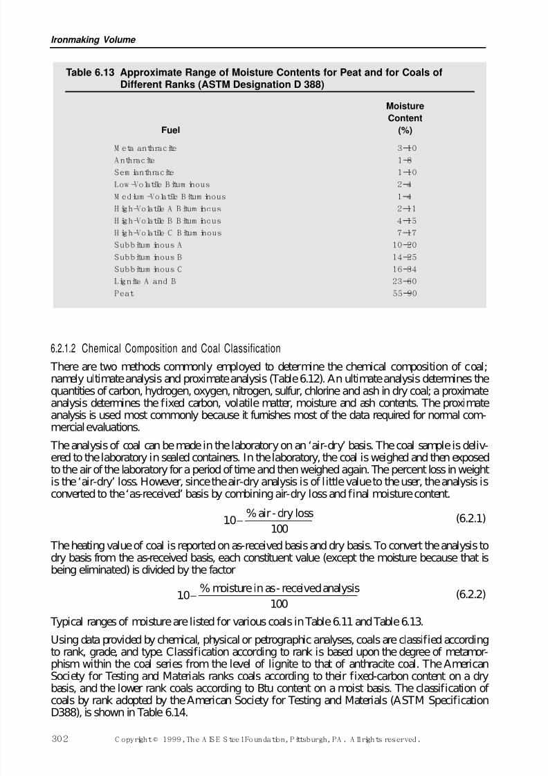
7/17/2019 Steel Plants Fuels and Water Consumption
http://slidepdf.com/reader/full/steel-plants-fuels-and-water-consumption 24/102
6.2.1.2 Chemical Composition and Coal Classification
There are two methods commonly employed to determine the chemical composition of coal;namely ultimate analysis and proximate analysis (Table 6.12). An ultimate analysis determines thequantities of carbon, hydrogen, oxygen, nitrogen, sulfur, chlorine and ash in dry coal; a proximate
analysis determines the fixed carbon, volatile matter, moisture and ash contents. The proximateanalysis is used most commonly because it furnishes most of the data required for normal com-mercial evaluations.
The analysis of coal can be made in the laboratory on an ‘air-dry’ basis. The coal sample is deliv-ered to the laboratory in sealed containers. In the laboratory, the coal is weighed and then exposedto the air of the laboratory for a period of time and then weighed again. The percent loss in weightis the ‘air-dry’ loss. However, since the air-dry analysis is of little value to the user, the analysis isconverted to the ‘as-received’ basis by combining air-dry loss and final moisture content.
(6.2.1)
The heating value of coal is reported on as-received basis and dry basis. To convert the analysis todry basis from the as-received basis, each constituent value (except the moisture because that isbeing eliminated) is divided by the factor
(6.2.2)
Typical ranges of moisture are listed for various coals in Table 6.11 and Table 6.13.
Using data provided by chemical, physical or petrographic analyses, coals are classified accordingto rank, grade, and type. Classification according to rank is based upon the degree of metamor-phism within the coal series from the level of lignite to that of anthracite coal. The American
Society for Testing and Materials ranks coals according to their fixed-carbon content on a drybasis, and the lower rank coals according to Btu content on a moist basis. The classification of coals by rank adopted by the American Society for Testing and Materials (ASTM SpecificationD388), is shown in Table 6.14.
10100
. −% moisture in as- received analysis
10100
. −% air-dry loss
Ironmaking Volume
302 C opyright © 1999, The A IS E S teel Foundation, Pittsburgh, PA . A ll rights reserved.
Table 6.13 Approximate Range of Moisture Contents for Peat and for Coals ofDifferent Ranks (ASTM Designation D 388)
Moisture
Content
Fuel (%)
M eta anthracite 3–10
A nthracite 1–8
Sem ianthracite 1–10
Low -Volatile B itum inous 2–4
M edium -Volatile B itum inous 1–4
H igh-Volatile A B itum inous 2–11
H igh-Volatile B B itum inous 4–15
H igh-Volatile C B itum inous 7–17
Subbitum inous A 10–20
Subbitum inous B 14–25
Subbitum inous C 16–34Lignite A and B 23–60
Peat 55–90
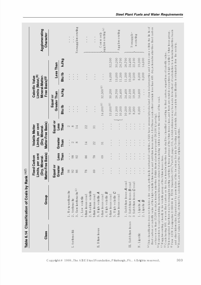
7/17/2019 Steel Plants Fuels and Water Consumption
http://slidepdf.com/reader/full/steel-plants-fuels-and-water-consumption 25/102
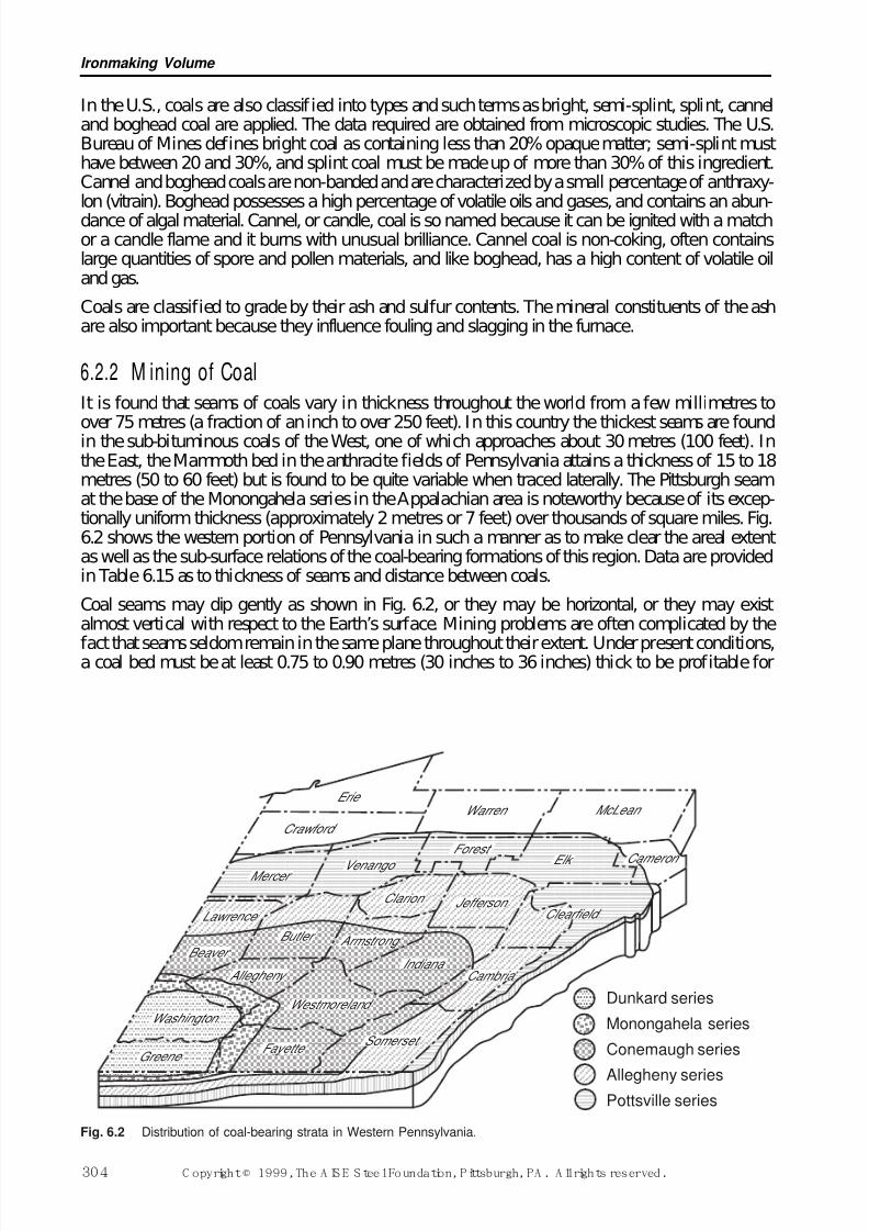
7/17/2019 Steel Plants Fuels and Water Consumption
http://slidepdf.com/reader/full/steel-plants-fuels-and-water-consumption 26/102
In the U.S., coals are also classified into types and such terms as bright, semi-splint, splint, canneland boghead coal are applied. The data required are obtained from microscopic studies. The U.S.Bureau of Mines defines bright coal as containing less than 20% opaque matter; semi-splint musthave between 20 and 30%, and splint coal must be made up of more than 30% of this ingredient.Cannel and boghead coals are non-banded and are characterized by a small percentage of anthraxy-lon (vitrain). Boghead possesses a high percentage of volatile oils and gases, and contains an abun-
dance of algal material. Cannel, or candle, coal is so named because it can be ignited with a matchor a candle flame and it burns with unusual brilliance. Cannel coal is non-coking, often containslarge quantities of spore and pollen materials, and like boghead, has a high content of volatile oiland gas.
Coals are classified to grade by their ash and sulfur contents. The mineral constituents of the ashare also important because they influence fouling and slagging in the furnace.
6.2.2 M ining of CoalIt is found that seams of coals vary in thickness throughout the world from a few millimetres to
over 75 metres (a fraction of an inch to over 250 feet). In this country the thickest seams are foundin the sub-bituminous coals of the West, one of which approaches about 30 metres (100 feet). Inthe East, the Mammoth bed in the anthracite fields of Pennsylvania attains a thickness of 15 to 18metres (50 to 60 feet) but is found to be quite variable when traced laterally. The Pittsburgh seamat the base of the Monongahela series in the Appalachian area is noteworthy because of its excep-tionally uniform thickness (approximately 2 metres or 7 feet) over thousands of square miles. Fig.6.2 shows the western portion of Pennsylvania in such a manner as to make clear the areal extentas well as the sub-surface relations of the coal-bearing formations of this region. Data are providedin Table 6.15 as to thickness of seams and distance between coals.
Coal seams may dip gently as shown in Fig. 6.2, or they may be horizontal, or they may existalmost vertical with respect to the Earth’s surface. Mining problems are often complicated by the
fact that seams seldom remain in the same plane throughout their extent. Under present conditions,a coal bed must be at least 0.75 to 0.90 metres (30 inches to 36 inches) thick to be profitable for
Ironmaking Volume
304 C opyright © 1999, The A IS E S teel Foundation, Pittsburgh, PA . A ll rights reserved.
Dunkard series
Monongahela series
Conemaugh series
Allegheny seriesPottsville series
E rie War r en M cLean
Craw f ord
Merc e r
Clarion
Forest
Jeffe r son
Camb r ia
Clea rfield
Elk C amero n
Som erset
Lawr e nce
Wa shingto n
Gr e ene
V e nango
Westm orelan d
F ayette
A lleghen y
B utler Arm s trong
India n a Bea v er
Fig. 6.2 Distribution of coal-bearing strata in Western Pennsylvania.
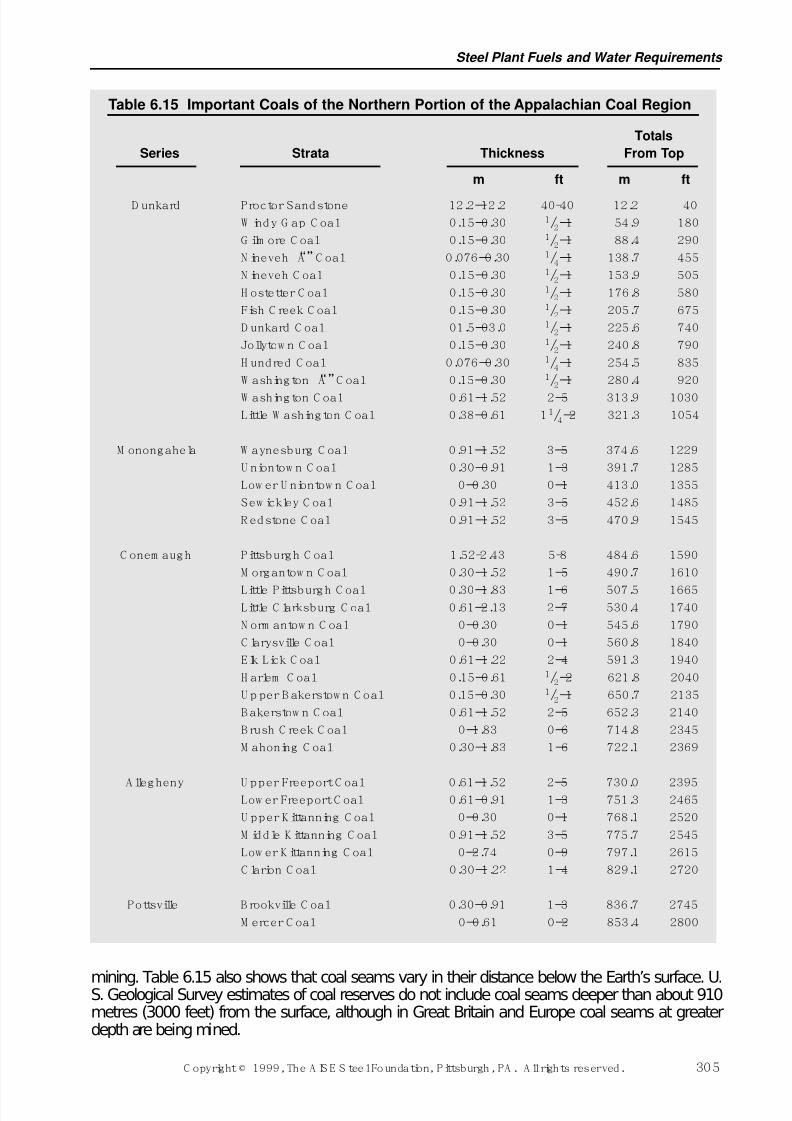
7/17/2019 Steel Plants Fuels and Water Consumption
http://slidepdf.com/reader/full/steel-plants-fuels-and-water-consumption 27/102
mining. Table 6.15 also shows that coal seams vary in their distance below the Earth’s surface. U.S. Geological Survey estimates of coal reserves do not include coal seams deeper than about 910metres (3000 feet) from the surface, although in Great Britain and Europe coal seams at greaterdepth are being mined.
Steel Plant Fuels and Water Requirements
C opyright © 1999, The A IS E S teel Foundation, Pittsburgh, PA . A ll rights reserved. 305
Table 6.15 Important Coals of the Northern Portion of the Appalachian Coal Region
Totals
Series Strata Thickness From Top
m ft m ft
D unkard Proctor Sandstone 12.2–12.2 40-40 12.2 40
W indy G ap C oal 0.15–0.30 1/2–1 54.9 180
G ilm ore C oal 0.15–0.30 1/2–1 88.4 290
N ineveh “A”C oal 0.076–0.30 1/4–1 138.7 455
N ineveh C oal 0.15–0.30 1/2–1 153.9 505
H ostetter C oal 0.15–0.30 1/2–1 176.8 580
Fish C reek C oal 0.15–0.30 1/2–1 205.7 675
D unkard C oal 01.5–03.0 1/2–1 225.6 740
Jollytow n C oal 0.15–0.30 1/2–1 240.8 790
H undred C oal 0.076–0.30 1/4–1 254.5 835
W ashington “A”C oal 0.15–0.30 1/2–1 280.4 920
W ashington C oal 0.61–1.52 2–5 313.9 1030
Little W ashington C oal 0.38–0.61 11/4–2 321.3 1054
M onongahela W aynesburg C oal 0.91–1.52 3–5 374.6 1229
U niontow n C oal 0.30–0.91 1–3 391.7 1285
Low er U niontow n C oal 0–0.30 0–1 413.0 1355
Sew ickley C oal 0.91–1.52 3–5 452.6 1485
R edstone C oal 0.91–1.52 3–5 470.9 1545
C onem augh Pittsburgh C oal 1.52-2.43 5-8 484.6 1590
M organtow n C oal 0.30–1.52 1–5 490.7 1610
Little Pittsburgh C oal 0.30–1.83 1–6 507.5 1665Little C larksburg C oal 0.61–2.13 2–7 530.4 1740
N orm antow n C oal 0–0.30 0–1 545.6 1790
C larysville C oal 0–0.30 0–1 560.8 1840
Elk Lick C oal 0.61–1.22 2–4 591.3 1940
H arlem C oal 0.15–0.61 1/2–2 621.8 2040
U p per B akerstow n C oal 0.15–0.30 1/2–1 650.7 2135
B akerstow n C oal 0.61–1.52 2–5 652.3 2140
B rush C reek C oal 0–1.83 0–6 714.8 2345
M ahoning C oal 0.30–1.83 1–6 722.1 2369
A llegheny U pper Freeport C oal 0.61–1.52 2–5 730.0 2395Low er Freeport C oal 0.61–0.91 1–3 751.3 2465
U pper K ittanning C oal 0–0.30 0–1 768.1 2520
M iddle K ittanning C oal 0.91–1.52 3–5 775.7 2545
Low er K ittanning C oal 0–2.74 0–9 797.1 2615
C larion C oal 0.30–1.22 1–4 829.1 2720
Pottsville B rookville C oal 0.30–0.91 1–3 836.7 2745
M ercer C oal 0–0.61 0–2 853.4 2800
7/17/2019 Steel Plants Fuels and Water Consumption
http://slidepdf.com/reader/full/steel-plants-fuels-and-water-consumption 28/102
The mining of coal is performed by either one of two methods: (1) open pit or stripping, also calledcontour mining, or (2) underground or deep mine. The first method involves removing the forma-tion (over-burden) above the seam by stripping with scrapers, bulldozers, or mechanically operatedshovels, followed by removing the exposed coal. Stripping is applied to coal seams which are rel-atively close to the surface, particularly to thick seams underlying overburden about 25 to 50metres (80 to 150 feet) deep, although the development or larger equipment and improved tech-
niques in recent years has justified removal of layers of overburden thicker than this. Auger min-ing is being used extensively to recover coal where the overburden is too great for strip-miningpractices to be employed. A large-diameter auger or drill with cutting bits on its end is propelledinto the exposed edge of a coal seam. As the auger progresses into and along the seam, the brokencoal is conveyed away from the face through the tube to the outside for transport away from theauger. Production by strip mining has increased greatly since World War I due to reduced labor andmaterial costs and a quicker return on capital investment compared to underground mining. In theU.S., surface mining accounted for slightly over 25% of the coal produced in 1957. By 1995, sur-face mining has climbed to about 62% of the total coal mined.
6.2.2.1 Underground Mining
Underground mining is performed by either the room-and-pillar or the longwall method. Theroom-and-pillar method is in more common use in the U.S. The longwall method is particularlyadaptable to mining seams up to about 4.6 metres (15 feet) thick under conditions where the roof may be permitted to cave. It is used more extensively in the mines of the eastern U.S. There are anumber of modifications applicable to each method. The room-and-pillar system consists essen-tially of working out rooms, chambers, or breasts in the coal seam from passages (entries) drivenfrom the mine entrance. Entrance to an underground mine is by drift, shaft or slope. The roomsvary in width from about 3.5 to 12 metres (12 feet to 40 feet), 6.1 metres (20 ft.) being the mostcommon, and from about 45 to 90 metres (150 feet to 300 feet) in length, depending on such fac-tors as weight and character of the overlying and underlying structure and thickness of seam. Pillars
separating the rooms vary in width from about 2 to 30 metres (6 feet to 100 feet), depending onconditions and mining practice. These pillars are sometimes removed by retreat mining and thecoal recovered.
In the longwall method, a continuous mining face is maintained in the coal seam. After mining, theroof is permitted to cave, about 5 to 9 metres (15 or 30 feet) from the mine working face.
Prior to the advent of mechanical mining, undercutting of the coal seam preparatory to blasting wasdone manually. Production per man was low by this method and required a number of workingfaces in the mine to produce high mine tonnage. Hand loading of coal into mule-drawn cars wasthe prevailing practice for many years until development of machinery for cutting, loading andhaulage. Electric trolley-type locomotives capable of hauling longer underground trains of cars of increased capacity displaced mule-drawn trains as mine capacity increased.
In some modern underground mines, the coal is carried out of the mine by a system of conveyorbelts to a shipping station or cleaning plant. In other mines, the coal is carried in mine cars to arotary dumper. From the dumper the coal is fed by way of a conveyor or elevator to a shipping sta-tion or cleaning plant.
6.2.2.2 Continuous Mining
The cutting machines and loading machines characteristic of mechanical mining in the past weresingle-purpose units, and each performed essentially a single function of mining at the workingface. After either unit completed its work it was withdrawn from the face to allow other units of
the production setup to move up to the face to carry out succeeding functions. To keep all operat-ing units working at full efficiency, it was necessary to have additional working places near at handso that the single-purpose machines could enter the places in rotation and carry out their functionswithout interference.
Ironmaking Volume
306 C opyright © 1999, The A IS E S teel Foundation, Pittsburgh, PA . A ll rights reserved.
7/17/2019 Steel Plants Fuels and Water Consumption
http://slidepdf.com/reader/full/steel-plants-fuels-and-water-consumption 29/102
To eliminate some of the difficulties attendant upon the addition of extra working places, multi-purpose machines known as continuous miners have been developed and the operation carried outby such machines has been given the name continuous mining. Continuous miners combine in asingle unit the actions of dislodging the coal from the solid seam and loading it into some unit of a transportation system. Such machines, therefore, combine in one operation the separate steps of cutting, drilling, blasting and loading common to earlier mechanical mining methods. Coal plan-
ers and shearers with long-wall mining achieve these combined objectives.
There are several types of continuous miners in operation, one of which is a ripper-type miner thathas cutting bits mounted in the rims of multiple wheels that are rotated to rip the coal out of theseam while the ripper wheels are propelled into and up or down in the coal seam. The coal that isripped loose from the seam falls into the gathering head of the loader, which has dual gatheringarms that sweep the broken coal into the conveyor section of the machine for loading into shuttlecars or other suitable conveying equipment.
Continuous miners of some other types employ auger-type cutters that bore into the face, the cutcoal in both cases being carried by a conveyor on the machine to a shuttle car or other means of transportation.
6.2.3 Coal PreparationAs one phase of coal preparation, the objective of coal cleaning (often called washing) is removalof solid foreign matter, such as rock and slate, from the coal prior to its use. Reduction of ash andsulfur contents; control of ash fusibility; increase of heating (calorific) value; and improvement of coking properties of the coal can be achieved by this practice. From a coal-cleaning standpoint, theimpurities in coal are of two types; namely, those which cannot be separated from the coal, usuallycalled fixed or inherent impurities; and those which can be removed, herein referred to as freeimpurities. Altogether, these impurities are of eight types, named as follows: (1) residual inorganicmatter of the coal-forming plants from which the coal was derived; (2) mineral matter washed or
blown into the coal-forming mass during the periods of its formation; (3) pyrites (FeS2) formed bybacterial reaction of iron and sulfur in the coal-forming matter; (4) sedimentary deposits during thecoal-forming periods which appear as partings, sometimes called “bone,” that usually must bemined with the coal; (5) massive deposits formed through deposition on bedding planes; (6) salinedeposits, somewhat rare in coal beds of the U.S.; (7) slate, shale, clay, etc. from the underlying andoverlying strata accidentally included in mining; and (8) water or moisture, which includes that nat-urally carried by the coal in air-dry condition, and excess moisture producing a condition of wet-ness. Items (1) (2) and, for the most part (3) form fixed ash, while (4), (5), (6), and (7) are partlyfree ash-forming materials that can be removed by hand-picking and suitable mechanical cleaningtreatments. Item (8) involves drying operations differing from those required to separate mineralimpurities, which is the primary objective of cleaning. Mechanical cleaning is possible because of
the difference in specific gravity between the major impurities and the coal, the density of the for-mer being 1.7 to 4.9, while pure coal has a density of about 1.3. Sulfur is present as pyrites, organiccompounds, and sulfates, and only part of the pyrites can be removed by cleaning. Phosphorus isusually associated more with bony and impure coal than with clean coal and is, therefore, reducedby washing. Salts, particularly the alkali chlorides, lower the fusion point of the ash, affect coke-oven linings and are troublesome in waste liquors from coking operations.
The advent of full-seam mechanical coal mining and the increasing need for metallurgical coke of low and uniform ash and sulfur contents has focused attention on the needs for the most efficienttypes of washers.
The preparation of coal starts at the production face in the mine. If loading is done by hand, the
miner is required to discard all rock and slate over 75 mm (3 in.) size. As practically all loadingis done mechanically in the U.S. little attempt is made to prepare the coal at the face other thanto control the tonnage from various sections of the mine if sulfur content of the coal is high orvariable.
Steel Plant Fuels and Water Requirements
C opyright © 1999, The A IS E S teel Foundation, Pittsburgh, PA . A ll rights reserved. 307
7/17/2019 Steel Plants Fuels and Water Consumption
http://slidepdf.com/reader/full/steel-plants-fuels-and-water-consumption 30/102
The cleaning qualities of a particular coal are determined by the float and sink test, commonlyreferred to as a washability test. Fundamentally, this test effects a fractionation of the coal by sizeand specific gravity. This test consists in crushing coal to proper size and floating individual sizesof it on liquids having specific gravities of 1.30, 1.40, 1.50, 1.60, etc., to determine the weight andcharacter of the material that floats and sinks in each liquid. The proportion of coal, and the ashand sulfur content of the different fractions, provides reasonably complete data on the washability
characteristics of a tested coal. Extreme fines may be evaluated by froth flotation.
Coal preparation is accomplished by a combination of crushing, sizing, cleaning, and dewateringoperations:
1. Crushinga) Mine breakersb) Bradford breakersc) Roll crushersd) Impact crushers
2. Sizinga) Grizzliesb) Vibrating screensc) Classifiersd) Cyclones
3. Cleaninga) Jigsb) Dense media processesc) Cyclone processesd) Tablese) Froth flotation
4. Dewatering
a) Screensb) Centrifugesc) Vacuum filtersd) Thermal dryers
By far the largest percentage of coal is cleaned by wet methods.
A complete description of each of the foregoing processes would be too lengthy for inclusionherein; hence only a brief review will be given of the principles of some of the more importanttypes of cleaning processes in use at present. A reference list for further study of this subject isappended to this chapter.
J igs were probably the earliest type of machine used in the mineral industry to separate materialsof different densities. They consist essentially of a box with a perforated base into which the mate-rial is placed, and by alternate surges of water upward and downward through the perforations,materials of different specific gravities stratify. Materials having the highest specific gravitiesremain at the bottom while the lighter material rises. With proper mechanical facilities, a continu-ous separation is achieved. While jigs are not very efficient in cleaning a mixture of various sizes,they are capable of satisfying some market requirements, and capacities up to about 450 metrictons (500 net tons) per hour have been obtained.
In dense-media processes, only a part of the power for separating coal and refuse is supplied by anupward flow of liquid, this separating power being supplemented by using a liquid medium whichis heavier than water. The medium employed is a mixture of water and some finely divided solid
material, such as sand, magnetite, or barite, which can be separated readily from the washed coaland reused. In the high-density suspension process, the upward flow is discarded entirely, the liq-uid medium consisting of a mixture which is just dense enough so that the coal floats in it, and theimpurities sink. The size of coal has less significance in the efficiency of this process than of those
Ironmaking Volume
308 C opyright © 1999, The A IS E S teel Foundation, Pittsburgh, PA . A ll rights reserved.
7/17/2019 Steel Plants Fuels and Water Consumption
http://slidepdf.com/reader/full/steel-plants-fuels-and-water-consumption 31/102
previously described, and material ranging from 1.6 to 254 mm (1/16 inch to 10 inches) can becleaned in one operation. However, difficulty is encountered in separating the solid material fromcoal of fine size. Capacities up to about 545 metric tons (600 net tons) per hour have been obtainedwith bituminous coal. The Chance cone method, which uses a mixture of sand and water, is alsowidely used in the U.S. The Tromp and Barvoys processes, using magnetite and barite respectivelyas the solid material in the mixture, are used extensively in Europe and in the U.S. In these
processes, the specific gravity of the mixture of solid material and water can be varied by chang-ing their proportions to suit the optimum conditions in cleaning. Agitation in the separating coneis supplied by an upward current of water and by mechanical stirring.
Cyclones, which have an inverted conical shape and are fed tangentially at the widest part of thecone, are used with the dense medium process to increase the separating rate of particles in themedium. This device is particularly effective on sizes between 3/4 inch (17 mm) and 100–mesh(0.15 mm). Cyclones can also be used in the absence of a specific medium, but the efficiency islower and they must often be combined in stages. In this practice they are referred to as hydro-clones or water-only cyclones.
Coal is also cleaned on table concentrators. Essentially these tables consist of a slightly inclined
rectangular surface having a series of parallel grooves or cleats. The tables are mechanically agi-tated to permit stratification of the light and heavy material and to cause the heavy material to movewith the long axis of the table. A current of water is introduced at the top edge of the table to washthe coal which has settled above the refuse to the discharge edge of the table. The refuse which set-tles underneath the coal moves longitudinally down the table and is discharged at the end. Tableshave been used principally for cleaning coal of the smaller sizes, from about 0.3 to 12.7 mm(48–mesh up to about 1/2 in.).
Froth flotation of coal involves agitating fine coal with a mixture of water and a relatively smallquantity of some frothing agent. In this process, coal is buoyed to the surface by the froth andremoved while refuse settles. It is widely used to recover coal finer than 100–mesh (150 mm).
With practically all wet-washing systems the water is recirculated. When the water passes throughthe dewatering screens it contains a considerable amount of small-size coal solids which must berecovered for efficiency reasons. Also, the circulating water and effluent from flotation must beclarified before it is returned to the cleaning unit. This clarification is accomplished in variousways, the most important being by the use of hydraulic cyclones followed by a Dorr-type thickener.Settling cones and settling tanks are also used for this purpose. Where the Dorr-type thickener andsettling tanks are used, it is customary to draw off the settlings in the form of a slurry containing40% to 60% solids and to further separate the slurry in a vacuum-type filter. The filters deliver aproduct with approximately 25% moisture. For a more complete discussion of dewatering andwaste disposal, the reader is referred to a standard book on coal preparation.
6.2.4 Carbonization of Coal The most important use of coal in the modern steel industry is in the manufacture of metallurgicalcoke, which is discussed in detail in Chapter 7.
The carbonization of coal in byproduct ovens entails the production of large amounts of coke-ovengas and tar, important fuels in the steel industry, as well as light oils and various coal chemicals. The yields of gas and tar are largely a matter of the type of coal used and the temperaturesemployed in coke manufacture.
6.2.5 Combustion of Solid Fuels The principal combustion reactions of solid fuels have been given in Section 6.1.2, and this pre-sent discussion will deal with operating factors pertinent to the combustion of solid fuels in steelplants.
Steel Plant Fuels and Water Requirements
C opyright © 1999, The A IS E S teel Foundation, Pittsburgh, PA . A ll rights reserved. 309
7/17/2019 Steel Plants Fuels and Water Consumption
http://slidepdf.com/reader/full/steel-plants-fuels-and-water-consumption 32/102
The combustion of coke in blast furnaces has been studied by a number of investigators, each of whom has found that combustion takes place in a relatively small space directly in front of eachtuyere.
Coke breeze, produced by screening coke at both the coke plant and blast furnaces, is utilized as afuel in steel plant boiler houses to generate steam and in ore-agglomerating plants. When used as
boiler fuel, coke breeze is burned on chain-grate stokers. Of importance in the combustion of cokebreeze on chain-grate stokers is the maintenance of a relatively uniform fuel bed on the grate,approximately 200 to 300 mm (8 to 12 in.) thick, to prevent blowholes, and a balanced or slightpositive pressure in the furnace at fuel-bed level. The operation of the grate should permit the nor-mal combustion of approximately 146 kilograms per square metre (30 pounds of coke breeze persquare foot) of effective grate area per hour. Chain-grate stokers are particularly adaptable to solidfuels with an ash of low fusion point. The design of front and back arches must take into consid-eration the fuel to be burned on chain-grate stokers. The arches are utilized to reflect heat andthereby aid ignition on the fuel bed.
Stokers for firing coal were generally used in steel plant boilers on units whose capacity is underapproximately 45,000 kilograms (100,000 pounds) of steam per hour and for units using exclu-
sively a solid fuel. They were often used on boilers to provide flexibility for the adjustment of boiler output to the steam load in plants where there is an insufficient or fluctuating supply of gaseous byproduct fuels. When coal is used as a boiler fuel today, pulverized boilers dominate thefield. The advantage of stokers lies in their ability to control easily the rate of combustion of a solidfuel with efficient use of air. The combustion process on stoker-fired boilers consists essentially infirst driving the volatile matter from a continuous supply of fuel, and then oxidizing the carbon inthe residue on the stoker. The combustion of the coke-like residue on the grate produces CO2 andCO. The CO and volatile matter are burned over the grate by secondary air admitted over the fuelbed. The temperature of the fuel bed is affected by the rate of firing and, at the top or hottest partof the bed, varies from about 1230°C (2250°F) at low to 1510°C (2750°F) at high rates. Theamount of primary air supplied determines the capacity of stoker-fired furnaces and the effective
use of secondary air determines the efficiency of combustion. In well operated and carefully sealedboilers, approximately 20 to 30% excess air will permit combustion of the gases within seven oreight feet above the grate.
Stokers are classified in general according to the travel of the fuel. In an overfired stoker the fuelis fed on top of the bed, and in an underfired or a retort stoker the fuel is fed at the bottom or sideof the bed. A traveling-grate or chain-grate stoker carries the bed horizontally on the flat upper sur-face of a conveyor as in a chain-grate stoker. There are a number of modifications of these stokertypes. The spreader stoker projects the coal into the furnace above the fuel bed and the fuel isburned both in suspension and on the fuel bed. While the fuel bed of a stoker-fired boiler is rela-tively thin, usually from 100 to 300 mm (4 to 12 in.), compared to a gas-producer bed, similar zonesof reaction occur. In overfired stokers the ash zone is immediately above the grate, followed by the
oxidation, reduction and distillation zones. In underfired or retort stokers the distillation of thevolatile matter takes place in an oxidizing atmosphere and the volatile products pass through theincandescent residue from combustion rather than through green coal, as in the case of overfiredstokers. The normal combustion rates on coal-fired stokers amounts to approximately 150 to 300kilograms of coal per square metre (30 to 60 pounds per square foot) of effective grate area perhour.
6.2.5.1 Pulverized Coal
The cement industry was the first to use pulverized (powdered) coal extensively as a fuel. Publicutilities and the steel industry began applying pulverized coal on an experimental basis as a boiler
fuel around 1917, and by 1935 practically all large boilers (above about 45,000 kilograms or100,000 pounds of steam per hour) in public utility power stations used this fuel, except for thosestations located in the vicinity of oil and natural gas fields where local fuels were more competi-tive than coal. Large modern boiler installations in integrated steel plants generally use pulverized
Ironmaking Volume
310 C opyright © 1999, The A IS E S teel Foundation, Pittsburgh, PA . A ll rights reserved.
7/17/2019 Steel Plants Fuels and Water Consumption
http://slidepdf.com/reader/full/steel-plants-fuels-and-water-consumption 33/102
coal if coal is utilized, either as a standby or as an auxiliary fuel, in conjunction with blast-furnacegas for steam or power generation. Although pulverized coal has been used as a fuel for metallur-gical purposes in steel plants, such as in open-hearth, reheating, forge and annealing furnaces,today it is employed as an injectant in the blast-furnace tuyere to increase furnace performance andefficiency.
Pulverized-coal firing offers important combustion advantages over grate firing and an economicadvantage over gaseous and liquid fuels in most sections of the country. Boiler capacities are notlimited as is the case with boilers equipped with stokers. Fine particles of coal burned in suspen-sion are capable of developing a highly luminous high-temperature flame. Coal in this form maybe burned normally with less excess of air above theoretical requirements than with a solid fuel,and the rate of heat release from the combustion of pulverized coal is greater than that accom-plished with the solid fuel. Coal, when pulverized to the degree common for boiler uses (70%through a 0.074 mm or 200–mesh screen), has the control flexibility of gaseous and liquid fuels.Practically all ranks of coal, from anthracite to lignite, can be pulverized for combustion and eachpossesses specific combustion characteristics which largely influence the extent of pulverization.Pulverized-coal firing in modern boilers has certain inherent problems. Excessive fly-ash dis-
charge from the stack, high operating power consumption rates, excessive pulverizer maintenancecost, erosion of induced-draft fan blades and other boiler components, and requirements for largefurnace volumes impose practical limitations in selecting this type of firing for low-capacity boil-ers. Dust collectors are required to control stack particulate emissions, while scrubbers are requiredto remove the sulfur from the waste gas stream.
The ash-disposal problem has been one of the principal deterrents to a more extended use of pul-verized coal. In the cement kiln, coal ash is no problem as it is absorbed by the cement in the kilnwithout adverse effect on the final product. In boilers, the principal difficulty of clogged boilertubes and deterioration of furnace walls has been overcome by the use of slagging-type furnaces inwhich the ash in molten form is granulated by water jets at the bottom of the furnace well. Theintroduction of the cyclone furnace, which offered the removal of the ash as liquid slag, further
increased the application of pulverized-coal firing for steam and power generation. This equipmentwas developed to solve two major problems that beset the power engineer: (1) the increasingnecessity to use low quality, high-ash fuels for steam generation; and (2) the requirement that asmuch of the coal ash as possible be kept in the furnace and not permitted to go through the furnaceand out of the stack. However, the removal of ash as a liquid slag requires the use of coal havingash of low fusion point and such special coal is sometimes difficult to obtain.
The problem of ash contamination resulting from burning fine particles of coal in suspensionabove a metallic liquid bath or mass of hot steel, damage to refractories from the chemical or phys-ical action of ash, and the clogging of furnace checkers or recuperators from ash accumulation, aswell as the normal availability of other fuels, has prevented widespread use of the fuel for metal-
lurgical purposes in steel plants.Pulverized coal offers high boiler efficiency, and means for quick regulation of boiler load. Therank of coal pulverized and the extent of pulverization particularly determine the speed of com-bustion. A high-volatile coal will burn faster than anthracite coal, also one with a lower ash con-tent will burn faster. The process of combustion with pulverized coal is similar to that of lump coalbut is of much higher velocity due to the introduction of the particle in suspension in a high-tem-perature chamber, and the greater surface exposure relative to weight. The release of volatile mat-ter in pulverized coal is practically instantaneous when blown into the furnace, and the speed of combustion of the resulting carbonized particle and volatile gases depends upon the thoroughnesswith which the pulverized coal has been mixed with air. High combustion temperatures, low ashlosses, and low excess air needs (10–20%), with resultant high boiler efficiencies (85– 90% with
good practice), make pulverized coal an ideal boiler fuel.
Air for combustion of pulverized fuel is generally preheated, with 10–50% of that required intro-duced ahead of the pulverizer and the balance made up at a point near the burner. This method of
Steel Plant Fuels and Water Requirements
C opyright © 1999, The A IS E S teel Foundation, Pittsburgh, PA . A ll rights reserved. 311
7/17/2019 Steel Plants Fuels and Water Consumption
http://slidepdf.com/reader/full/steel-plants-fuels-and-water-consumption 34/102
introducing the air helps dry the coal and maintains a nonexplosive mix in the pulverized coaltransmission system.
The combustion chamber size for pulverized coal is generally proportioned for a heat-release rangeof from approximately 207,000–1,035,000 watts per cubic metre or 745,000–3,725,000 kilojoulesper cubic metre per hour (20,000–100,000 Btu per cubic foot per hour) of combustion space.
However, the cyclone furnace has heat-release rates of approximately 5,175,000–9,315,000 wattsper cubic metre or 18,625,000–33,525,000 kilojoules per cubic metre per hour (500,000–900,000Btu per cubic foot per hour) within the cyclone chamber and the boiler furnace is used only forextracting heat from the flue gases. The difference in requirements is dependent upon whether pul-verized coal is the sole fuel to be used in the chamber, the size of the coal particles, the rank of coal to be pulverized, the ash-slagging temperature of the coal, and the desired temperature for thecombustion chamber. Spreader-stoker installations offer low first cost for smaller-size boilers, andthe fly-ash emission from the boiler is not as severe as with the pulverized-fuel boilers.
Another technology is fluidized bed combustion which has been used to provide emission controlfor high sulfur coals. In this type of firing, the fuel limestone sorbent particles are kept suspendedand bubbling or fluidized in the lower section of the furnace through the action of air under pres-
sure through a series of orifices in a lower distribution plate. The fluidization promotes the turbu-lent mixing required for good combustion, which in turn promotes the three required parametersfor efficient combustion; time, turbulence, and temperature. The limestone captures the freed sul-fur from the coal products of combustion to form calcium sulfate. The mixture of ash and sulfatedlimestone sorbent discharged is a relatively inert material, disposal of which presents little hazard. This type firing also achieves a measure of NOx control in that it burns at a lower temperature,somewhat below maximum NOx formation.
6.3 Liquid Fuels and Their UtilizationLiquid fuels are essential to practically all parts of the American transportation system. The move-ment of passengers and freight by highway and air is dependent upon gasoline and other productsof petroleum. The railways of the country have nearly all been equipped with diesel locomotivespowered by fuel oil. Nearly all ocean-going ships are driven by oil, as are the majority of lake andriver craft. Liquid fuels have also become of major importance as a source of heat and power inmanufacturing plants. The particular advantages of petroleum as a source of energy and the avail-able supplies have brought about a phenomenal growth in the petroleum industry.
The oil industry has recovered from the traumatic price increases of the 1970s and early 1980swhich temporarily reduced the demand for oil products. The U.S. domestic demand for all oil prod-ucts reached its low point in 1983 at 2.42 million cubic metres (15.23 million barrels) per day and
returned to its highest level since 1979 in 1994 at 2.82 million cubic metres (17.72 million barrels)per day. During this period, the share of crude oil produced by the domestic oil industry has con-tinued a steady decline to 1.06 million cubic metres (6.66 million barrels) per day in 1994 sincereaching a peak of 1.53 million cubic metres (9.64 million barrels) per day in 1970. Unless a majornew field is discovered, this decline in production and reserves will continue indefinitely.
Worldwide crude oil production in 1994 was also back to its highest levels since 1979 with a pro-duction rate of 9.63 million cubic metres (60.58 million barrels) per day with OPEC countriesaccounting for 41.1% of the total. This is still well below the 48.9% share OPEC held in 1979.Fortunately, as consumption of oil products has risen over the last decade, so has the known world-wide reserves. These reserves have stood at nearly 159 billion cubic metres (1,000 billion barrels)since the beginning of the 1990s. This is over 30% above the levels of the 1970s with the OPEC
countries accounting for the majority of the increase.
Fuel oil is the principal liquid fuel used in the steel industry. Tar and pitch consumption has overthe years decreased considerably. Fuel oil is utilized predominantly in the blast furnace as an injec-
Ironmaking Volume
312 C opyright © 1999, The A IS E S teel Foundation, Pittsburgh, PA . A ll rights reserved.
7/17/2019 Steel Plants Fuels and Water Consumption
http://slidepdf.com/reader/full/steel-plants-fuels-and-water-consumption 35/102
tant for coke replacement, in reheating furnaces as a substitute for gaseous fuels and in boilers asa backup fuel for other byproduct fuels.
Tar and pitch are byproducts of the manufacture of coke. The virgin tar as it comes from the ovenscontains valuable tar-liquor oils which can be extracted and the residue pitch used as a fuel. It iscustomary to mix virgin tar with this highly viscous residue to provide fluidity for facilitating han-
dling and burning, or to utilize tar in which only the lighter products have been removed by a top-ping process by which sufficient fluidity is retained. Pitch-tar mixtures and topped tar makeavailable for use as a fuel 78 to 83% of the heat in the crude tar recovered in the distillation process.
6.3.1 Or igin, Composit ion and Dist r ibuti on of Petr oleumClassified according to their origins, three main types of rocks make up the outer crust of the earth:igneous, sedimentary and metamorphic rocks. Igneous rocks are formed from magma, a molten(liquid or pasty) rock material originating at high pressures and temperatures within the earth. Lavais magma that reaches the surface in the liquid or pasty state. Very commonly, the magma coolsand solidifies before reaching the surface. In any case, when the molten material cools sufficiently
to become solid, igneous rocks are the result. If cooling is slow, the rocks will be crystalline (gran-ite, for example); but if the cooling is rapid, the rocks will not be crystalline but glassy in nature(obsidian, for example). Because of the nature of their origin and their usually dense, nonporousstructures, igneous rocks are never hosts to petroleum deposits.
Sedimentary rocks are formed from eroded particles of rocks and soil, carried away by wind orwater (and sometimes glacial action) and deposited in seas, lakes, valleys and deltas in relativelyeven, sometimes very thick, beds or strata (sandstones and shales are formed from deposits of thistype). Other types of stratified deposits may be formed by evaporation of land-locked seas (bedsof rock salt), by accumulation of the mineral remains of animals (composed chiefly of calcium car-bonate, which is the principal constituent of limestone), or by chemical precipitation (gypsum andsome limestones originate in this manner). The beds of sand, silt, clay, calcium carbonate or what-
ever eventually are covered by other sedimentary deposits, sometimes to very great depths. Withthe passage of long periods of time, pressure of the overlying strata, heat, cementation by chemi-cal means, earth movements, or a combination of these or other agencies, the strata are consoli-dated into sedimentary rocks, typified by the few mentioned parenthetically earlier. Petroleumoccurs almost entirely in sedimentary rock formations, principally sandstones and limestones,under certain ideal conditions to be described later.
Metamorphic rocks originally were sedimentary or igneous rocks. Their composition, constitutionor structure have been changed through the single or combined action of natural forces such asheat, pressure, or other agencies. Marble, for example, is metamorphosed limestone.
The organic theory of the origin of petroleum, generally accepted by geologists, is that petroleum
has been derived from either animal or vegetable matter, or both, by a process of slow distillation,after its burial under beds of sediments. There is evidence to indicate that the animal and vegetablematter was of marine origin; such evidence includes the association of brines with oil, the visibleoily coating on seaweed found in certain localities, and the optical phenomenon of light polariza-tion by oils similar to that of substances found in certain plants and animals and which is not shownby inorganically synthesized petroleum. The accumulation of the matter from which petroleum hasbeen derived, its burial by sedimentary material, and the action of pressure and heat to cause dis-tillation, has resulted in petroleum formation in many parts of the world. Geological studies indi-cate that petroleum was not formed in the pools in which it is found, but that the action of waterpressing against oil formations caused the petroleum to flow, over a period of many years, throughporous beds or strata to points of accumulation. Pools of oil occur in traps in sedimentary rocks
such as sandstone or limestone. Essentially, such traps are formed by an impervious layer whichprevents upward migration of the petroleum to any further extent. The oil is obtained by drillingwells into these zones of accumulation. The well is encased in a steel pipe through which it is oftencustomary to run a number of smaller pipes to bring the product to the surface. These traps may be
Steel Plant Fuels and Water Requirements
C opyright © 1999, The A IS E S teel Foundation, Pittsburgh, PA . A ll rights reserved. 313
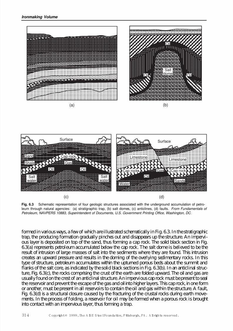
7/17/2019 Steel Plants Fuels and Water Consumption
http://slidepdf.com/reader/full/steel-plants-fuels-and-water-consumption 36/102
formed in various ways, a few of which are illustrated schematically in Fig. 6.3. In the stratigraphictrap, the producing formation gradually pinches out and disappears up the structure. An impervi-ous layer is deposited on top of the sand, thus forming a cap rock. The solid black section in Fig.6.3(a) represents petroleum accumulated below the cap rock. The salt dome is believed to be theresult of intrusion of large masses of salt into the sediments where they are found. This intrusioncreates an upward pressure and results in the doming of the overlying sedimentary rocks. In thistype of structure, petroleum accumulates within the upturned porous beds about the summit andflanks of the salt core, as indicated by the solid black sections in Fig. 6.3(b). In an anticlinal struc-ture, Fig. 6.3(c), the rocks comprising the crust of the earth are folded upward. The oil and gas areusually found on the crest of an anticlinal structure. An impervious cap rock must be present to sealthe reservoir and prevent the escape of the gas and oil into higher layers. This cap rock, in one form
or another, must be present in all reservoirs to contain the oil and gas within the structure. A fault,Fig. 6.3(d) is a structural closure caused by the fracturing of the crustal rocks during earth move-ments. In the process of folding, a reservoir for oil may be formed when a porous rock is broughtinto contact with an impervious layer, thus forming a trap.
Ironmaking Volume
314 C opyright © 1999, The A IS E S teel Foundation, Pittsburgh, PA . A ll rights reserved.
(a) (b)
Oil
Oil Oil
Saltdome
(c) (d)
Surface
Sand
Shale
Saltwater
Oil Oil
Cap rock
Saltwater
Limestone
Cap rock Gas
Oil
WaterSands
Cap rock
Limestone
Surface
Gas
Fig. 6.3 Schematic representation of four geologic structures associated with the underground accumulation of petro-
leum through natural agencies: (a) stratigraphic trap, (b) salt domes, (c) anticlines, (d) faults. From Fundamentals of
Petroleum, NAVPERS 10883, Superintendent of Documents, U.S. Government Printing Office, Washington, DC.
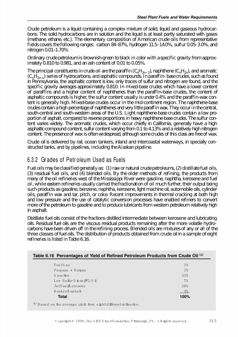
7/17/2019 Steel Plants Fuels and Water Consumption
http://slidepdf.com/reader/full/steel-plants-fuels-and-water-consumption 37/102
Crude petroleum is a liquid containing a complex mixture of solid, liquid and gaseous hydrocar-bons. The solid hydrocarbons are in solution and the liquid is at least partly saturated with gases(methane, ethane, etc.). The elementary composition of American crude oils from representativefields covers the following ranges: carbon 84–87%, hydrogen 11.5–14.0%, sulfur 0.05–3.0%, andnitrogen 0.01–1.70%
Ordinary crude petroleum is brownish-green to black in color with a specific gravity from approx-imately 0.810 to 0.981, and an ash content of 0.01 to 0.05%.
The principal constituents in crude oil are the paraffin (CnH2n2), naphthene (CnH2n), and aromatic(CnH2n–x) series of hydrocarbons, and asphaltic compounds. In paraffin- base crudes, such as foundin Pennsylvania, the asphaltic content is low, only traces of sulfur and nitrogen are found, and thespecific gravity averages approximately 0.810. In mixed-base crudes which have a lower contentof paraffins and a higher content of naphthenes than the paraffin-base crudes, the content of asphaltic compounds is higher, the sulfur content usually is under 0.4% and the paraffin-wax con-tent is generally high. Mixed-base crudes occur in the mid-continent region. The naphthene-basecrudes contain a high percentage of naphthenes and very little paraffin wax. They occur in the central,south-central and south-western areas of the U.S. Light naphthene-base crudes contain a low pro-
portion of asphalt, compared to reverse proportions in heavy naphthene-base crudes. The sulfur con-tent varies widely. The aromatic crudes, which occur chiefly in California, generally have a highasphaltic-compound content, sulfur content varying from 0.1 to 4.13% and a relatively high nitrogencontent. The presence of wax is often widespread, although some crudes of this class are free of wax.
Crude oil is delivered by rail, ocean tankers, inland and intercoastal waterways, in specially con-structed tanks, and by pipelines, including the Alaskan pipeline.
6.3.2 Gr ades of Petr oleum Used as FuelsFuel oils may be classified generally as: (1) raw or natural crude petroleums, (2) distillate fuel oils,(3) residual fuel oils, and (4) blended oils. By the older methods of refining, the products frommany of the oil refineries west of the Mississippi River were gasoline, naphtha, kerosene and fueloil, while eastern refineries usually carried the fractionation of oil much further, their output beingsuch products as gasoline, benzene, naphtha, kerosene, light machine oil, automobile oils, cylinderoils, paraffin wax and tar, pitch, or coke. Recent improvements in thermal cracking at both highand low pressure and the use of catalytic conversion processes have enabled refiners to convertmore of the petroleum to gasoline and to produce lubricants from western petroleum relatively highin asphalt.
Distillate fuel oils consist of the fractions distilled intermediate between kerosene and lubricatingoils. Residual fuel oils are the viscous residual products remaining after the more volatile hydro-carbons have been driven off in the refining process. Blended oils are mixtures of any or all of the
three classes of fuel oils. The distribution of products obtained from crude oil in a sample of eightrefineries is listed in Table 6.16.
Steel Plant Fuels and Water Requirements
C opyright © 1999, The A IS E S teel Foundation, Pittsburgh, PA . A ll rights reserved. 315
Table 6.16 Percentages of Yield of Refined Petroleum Products from Crude Oil (a)
Fuel G as 2%
Propane B utane 5%
G asoline 55%
Low Sulfur D iesel/#2 O il 7%
Jet Fuel/K erosene 28%
B unker/A sphalt 3%
Total 100%
(a) B ased on the average yield from eight different refineries.
7/17/2019 Steel Plants Fuels and Water Consumption
http://slidepdf.com/reader/full/steel-plants-fuels-and-water-consumption 38/102
6.3.3 Properties and Specifications of Liquid FuelsBefore discussing the more important properties and specifications of fuel oil, some of the com-mon terms will be reviewed. Further details may be found in the ASTM Standards for Petroleum,Section 5, cited in the references at the end of this chapter.
Specific gravity is the ratio of the weight of a volume of a body to the weight of an equal volumeof some standard substance. In the case of liquids, the standard is water. Baumé gravity is an arbi-trary scale for measuring the density of a liquid, the unit being called Baumé degree. Its relation tospecific gravity is shown by the formula:
(6.3.1)
For example, the Baumé hydrometer will read 10°Bé in pure water, when the specific gravity scalereads 1.00.
The American Petroleum Institute (API) Gravity is a modification of the Baumé scale for light liq-uids. API gravities are always reported at 15°C (60°F). The relation between API gravity and spe-
cific gravity is:
(6.3.2)
The greater the degrees Baumé or API, the lighter or lower in density the fluid. There are roughly90 API degrees between the heaviest and lightest oils which, therefore, make this scale valuable fordetermining differences between the density of various oils.
Flash point is the lowest temperature at which, under specified conditions, a liquid fuel vaporizesrapidly enough to form above its surface an air and vapor mixture which gives a flash or slightexplosion when ignited by a small flame. It is an indication of the ease of combustion or of the fire
hazard in handling or using oil.Pour point is the lowest temperature at which oil will pour or flow when chilled without disturbanceunder specified conditions.
Viscosity is the property of liquids that causes them to resist instantaneous change of shape orrearrangement of their parts due to internal friction. Since this property has a direct relation toresistance of flow in fuel-oil pipe systems and to atomization, it is an important specification.
Absolute viscosity is a measure of internal fluid friction. It is defined as the tangential force on unitarea of either of two parallel planes a unit distance apart when the space between the two planes isfilled with liquid and one of the planes moves relative to the other with unit velocity in its ownplane, and is also referred to as dynamic viscosity.
The unit for expressing absolute viscosity in SI is the Pascal-second (Pa s). By definition the pas-cal equals one Newton per square metre (N/m2) and the Newton has the formula kg m/s2, thus thedimensions for the Pascal-second are kilograms per second per metre (kg/s/m). One Pascal-secondis equal to 0.1 poise or 10 centipoises (the poise and centipoise are defined below).
The cgs unit of absolute viscosity is the poise, which has the dimensions, grams per centimetre persecond (g/s/cm). The centipoise is 1/100 of a poise and is the unit of absolute viscosity most com-monly used in cgs. One poise equals 10 Pa s (the SI unit) and one centipoise equals 0.1 Pa s.
Absolute viscosity in the fps system is expressed in pounds force per second per foot (lbf/s/ft) Theabsolute viscosity of water at 20°C (68°F) in SI equals 0.1 Pa s; in the cgs system it equals 1 cen-tipoise; and in the fps system it equals 0.00209 lbf/s/ft.
Relative viscosity of a fluid is defined as the ratio of the absolute viscosity of the fluid to theabsolute viscosity of water, with both the fluid and water at the same temperature and with theirrespective viscosity measured in the same units.
oAPI = −1415
1315.
.Sp. Gr.
Beo = −140
130Sp. Gr.
(for liquids lighter than water)
Ironmaking Volume
316 C opyright © 1999, The A IS E S teel Foundation, Pittsburgh, PA . A ll rights reserved.
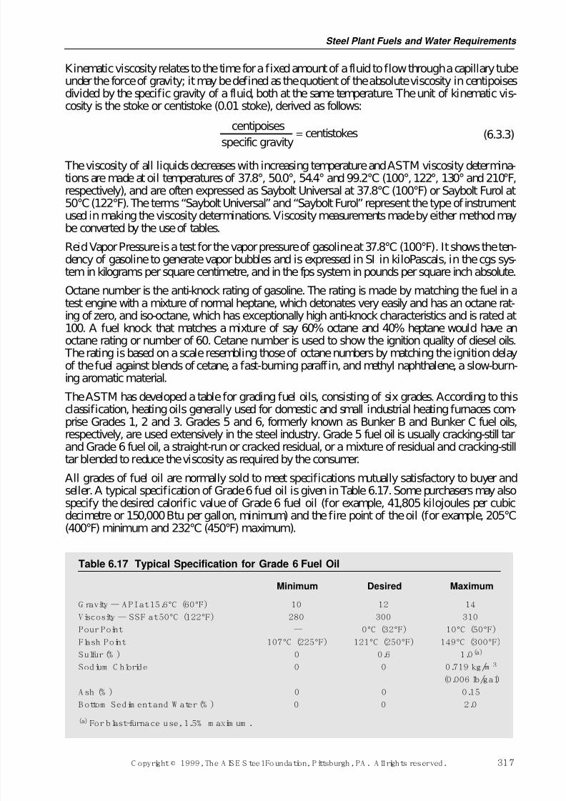
7/17/2019 Steel Plants Fuels and Water Consumption
http://slidepdf.com/reader/full/steel-plants-fuels-and-water-consumption 39/102
Kinematic viscosity relates to the time for a fixed amount of a fluid to flow through a capillary tubeunder the force of gravity; it may be defined as the quotient of the absolute viscosity in centipoisesdivided by the specific gravity of a fluid, both at the same temperature. The unit of kinematic vis-cosity is the stoke or centistoke (0.01 stoke), derived as follows:
(6.3.3)
The viscosity of all liquids decreases with increasing temperature and ASTM viscosity determina-tions are made at oil temperatures of 37.8°, 50.0°, 54.4° and 99.2°C (100°, 122°, 130°and 210°F,respectively), and are often expressed as Saybolt Universal at 37.8°C (100°F) or Saybolt Furol at50°C (122°F). The terms “Saybolt Universal” and “Saybolt Furol” represent the type of instrumentused in making the viscosity determinations. Viscosity measurements made by either method maybe converted by the use of tables.
Reid Vapor Pressure is a test for the vapor pressure of gasoline at 37.8°C (100°F). It shows the ten-dency of gasoline to generate vapor bubbles and is expressed in SI in kiloPascals, in the cgs sys-tem in kilograms per square centimetre, and in the fps system in pounds per square inch absolute.
Octane number is the anti-knock rating of gasoline. The rating is made by matching the fuel in atest engine with a mixture of normal heptane, which detonates very easily and has an octane rat-ing of zero, and iso-octane, which has exceptionally high anti-knock characteristics and is rated at100. A fuel knock that matches a mixture of say 60% octane and 40% heptane would have anoctane rating or number of 60. Cetane number is used to show the ignition quality of diesel oils. The rating is based on a scale resembling those of octane numbers by matching the ignition delayof the fuel against blends of cetane, a fast-burning paraffin, and methyl naphthalene, a slow-burn-ing aromatic material.
The ASTM has developed a table for grading fuel oils, consisting of six grades. According to thisclassification, heating oils generally used for domestic and small industrial heating furnaces com-
prise Grades 1, 2 and 3. Grades 5 and 6, formerly known as Bunker B and Bunker C fuel oils,respectively, are used extensively in the steel industry. Grade 5 fuel oil is usually cracking-still tarand Grade 6 fuel oil, a straight-run or cracked residual, or a mixture of residual and cracking-stilltar blended to reduce the viscosity as required by the consumer.
All grades of fuel oil are normally sold to meet specifications mutually satisfactory to buyer andseller. A typical specification of Grade 6 fuel oil is given in Table 6.17. Some purchasers may alsospecify the desired calorific value of Grade 6 fuel oil (for example, 41,805 kilojoules per cubicdecimetre or 150,000 Btu per gallon, minimum) and the fire point of the oil (for example, 205°C(400°F) minimum and 232°C (450°F) maximum).
Table 6.17 Typical Specification for Grade 6 Fuel Oil
Minimum Desired Maximum
G ravity — API at 15.6°C (60°F) 10 12 14
Viscosity — SSF at 50°C (122°F) 280 300 310
Pour Point — 0°C (32°F) 10°C (50°F)
Flash Point 107°C (225°F) 121°C (250°F) 149°C (300°F)
Sulfur (% ) 0 0.6 1.0(a)
Sodium C hloride 0 0 0.719 kg/m 3
(0.006 lb/gal)
A sh (% ) 0 0 0.15
B ottom Sedim ent and W ater (% ) 0 0 2.0
(a) For blast-furnace use, 1.5% m axim um .
centipoises
specific gravitycentistokes
=
Steel Plant Fuels and Water Requirements
C opyright © 1999, The A IS E S teel Foundation, Pittsburgh, PA . A ll rights reserved. 317
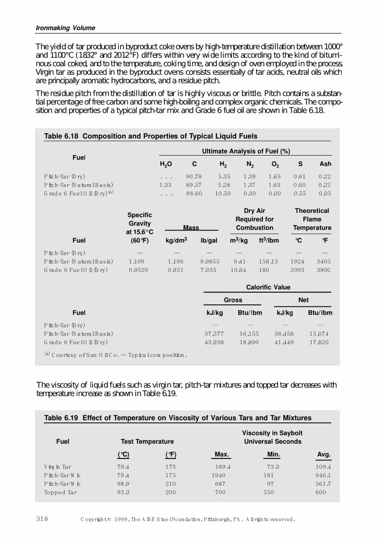
7/17/2019 Steel Plants Fuels and Water Consumption
http://slidepdf.com/reader/full/steel-plants-fuels-and-water-consumption 40/102
The yield of tar produced in byproduct coke ovens by high-temperature distillation between 1000°and 1100°C (1832° and 2012°F) differs within very wide limits according to the kind of bitumi-nous coal coked, and to the temperature, coking time, and design of oven employed in the process.Virgin tar as produced in the byproduct ovens consists essentially of tar acids, neutral oils whichare principally aromatic hydrocarbons, and a residue pitch.
The residue pitch from the distillation of tar is highly viscous or brittle. Pitch contains a substan-tial percentage of free carbon and some high-boiling and complex organic chemicals. The compo-sition and properties of a typical pitch-tar mix and Grade 6 fuel oil are shown in Table 6.18.
Ironmaking Volume
318 C opyright © 1999, The A IS E S teel Foundation, Pittsburgh, PA . A ll rights reserved.
Table 6.18 Composition and Properties of Typical Liquid Fuels
Ultimate Analysis of Fuel (%)Fuel
H2O C H2 N2 O2 S Ash
Pitch-Tar (D ry) . . . 90.78 5.35 1.39 1.65 0.61 0.22
Pitch-Tar (N atural B asis) 1.33 89.57 5.28 1.37 1.63 0.60 0.22
G rad e 6 Fuel O il (D ry)(a) . . . 88.60 10.50 0.30 0.00 0.55 0.05
SpecificDry Air Theoretical
GravityRequired for Flame
at 15.6°CMass Combustion Temperature
Fuel (60°F) kg/dm3 lb/gal m3/kg ft3/lbm °C °F
Pitch-Tar (D ry) — — — — — — —
Pitch-Tar (N atural B asis) 1.199 1.196 9.9855 9.41 158.13 1924 3495
G rade 6 Fuel O il (D ry) 0.9529 0.951 7.935 10.64 180 2093 3800
Calorific Value
Gross Net
Fuel kJ/kg Btu/ lbm kJ/kg Btu/ lbm
Pitch-Tar (D ry) — — — —
Pitch-Tar (N atural B asis) 37,577 16,155 36,458 15,674
G rade 6 Fuel O il (D ry) 43,938 18,890 41,449 17,820
(a) C ourtesy of Sun O il C o.— Typical com position.
The viscosity of liquid fuels such as virgin tar, pitch-tar mixtures and topped tar decreases withtemperature increase as shown in Table 6.19.
Table 6.19 Effect of Temperature on Viscosity of Various Tars and Tar Mixtures
Viscosity in Saybolt
Fuel Test Temperature Universal Seconds
(°C) (°F) Max. Min. Avg.
Virgin Tar 79.4 175 189.4 73.3 109.4
Pitch-Tar M ix 79.4 175 1940 181 946.1Pitch-Tar M ix 98.9 210 687 97 561.7
Topped Tar 93.3 200 700 550 600
7/17/2019 Steel Plants Fuels and Water Consumption
http://slidepdf.com/reader/full/steel-plants-fuels-and-water-consumption 41/102
6.3.4 Combustion of Liquid Fuels The combustion of liquid fuel usually is obtained by atomizing the fuel. Atomization breaks up thefuel into fine, mist-like globules, thus permitting an increased area for intimate contact betweenthe air supplied for combustion and the fuel. The chemistry of combustion of liquid fuels is com-plex. The small particles of fuel either vaporize to form gaseous hydrocarbons which burn to CO2
and H2O through a chain of reactions, or the fuel cracks to form carbon (soot) and hydrogen whichalso burn with complete combustion to CO2 and H2O. Both of these conditions normally occur inthe combustion of liquid fuels. The first condition predominates with good atomization and propermixing with suff icient air. A deficiency of air or poor atomization will cause smoke. For large fur-naces the atomizing agent is usually steam at a pressure anywhere between 415 and 860 kPa(60 and 125 pounds per square inch) gauge. The steam consumed in atomization varies from 0.3to 0.7 kilograms per kilogram of fuel. When liquid fuels are used in smaller furnaces, atomizationusually is achieved by compressed air or by mechanical action. The character of a liquid-fuel flame,that is, its shape, size and luminosity, may be altered with a fixed burner design by changing thedegree of atomization which is controlled by the steam pressure. Liquid fuels normally are burnedin steel plants to produce a highly luminous flame at an intensity of flame propagation intermedi-
ate between that generally secured with coke-oven gas and that with natural gas.Liquid fuels are often preferred because they permit better control of flame direction and, becauseof their high calorific value, control of flame temperature and luminosity.
The amount of air required to burn liquid fuels depends upon the chemical composition of the par-ticular fuel. Grade 6 fuel oil requires approximately 10.64 m3per kilogram (180 ft3per lbm) of dryair for perfect combustion, and tar-pitch approximately 9.34 m3 (158 ft3). From the ultimate analy-sis of a liquid fuel, the theoretical air requirements and products of combustion may be calculated,as explained in Section 6.1.2.5.
6.3.5 Liquid-Fuel Burners There are many different designs of burners for liquid fuels. Burners designed for atomization bysteam or air may be classified into two general types, the inside mixing and the outside mixing. Inthe inside-mixing type the fuel and atomizing agent are mixed inside the burner or burner system,while in the outside-mixing type the two fluids meet immediately outside the burner tip. In largereheating furnaces the inside-mixing type is used. The inside-mixing type is sometimes classifiedas an emulsion type or a nozzle-mix type of burner. In the emulsion type the mixing is performedat a point several feet from the burner tip, while in the nozzle-mix type the two fluids meet insidethe burner but very close to the burner tip. In the latter type, mixing probably takes place bothinside the burner and as the stream enters the furnace. Liquid-fuel burners used in reheating, forgeand annealing furnaces seldom require water cooling.
The handling of liquid fuels at consuming plants requires a system for their transportation, storageand conditioning. Where liquid fuels are received by tank car, a system of receiving basins, unload-ing pumps, strainers and storage tanks generally is required. The storage tanks must be of amplesize to meet fuel demands between deliveries and should be provided with heaters to maintainproper fluidity for flow through pipelines to the system pressure pumps. Pressure pumps are usedto deliver the liquid fuel through a pipe system to the point of consumption. Where there are a num-ber of consuming units being served from a common fuel-storage system, the pipe feeder line isdesigned in the form of a loop through which the fuel flows at constant pressure and temperature. The various units tap into this loop. The fuel-oil lines are lagged and provided with tracer steamlines to maintain uniform fluidity throughout the system and to provide fuel at the burners at theproper viscosity for atomization. The temperature at which liquid fuel is delivered to the burners
varies with the character of the fuel and burner design. Where pitch is used, a temperature as highas 150°C (approximately 300°F) in the lines is sometimes required. A temperature level usuallysomewhere between 95° and 120°C (approximately 200° and 250°F) is maintained for pitch-tarmixtures, and 65° and 95°C (approximately 150° and 200°F) for Grade 6 fuel oil. Additional
Steel Plant Fuels and Water Requirements
C opyright © 1999, The A IS E S teel Foundation, Pittsburgh, PA . A ll rights reserved. 319
7/17/2019 Steel Plants Fuels and Water Consumption
http://slidepdf.com/reader/full/steel-plants-fuels-and-water-consumption 42/102
details on burners and firing practices for liquid fuels appear in several references cited at the endof this chapter.
6.4 Gaseous Fuels and Their Utilization The availability of natural gas in so many sections of this country has had a profound influenceupon our industrial progress. It was first used as an illuminating gas at Fredonia, New York, in1821. The discovery of new fields and the installation of pipelines to consuming centers led toincreasing demands, as the convenience, cleanliness, and general utility of this form of fuel becamebetter known. The initial use of natural gas for steel manufacture was at a rolling mill plant atLeechburg, Pa., in 1874. A well in this area permitted exclusive use of natural gas for puddling,heating, and steam generation for a period of six months. Since 1932 there has been an accelerateddemand for natural gas, which peaked in 1972 at 0.626 trillion cubic metres (22.10 trillion cubicfeet). The rapid price escalation which followed the oil shocks cut demand by 1986 to less than75% of the previous peaks. As supplies have increased and prices have fallen, the consumption of natural gas has returned to 0.587 trillion cubic metres (20.73 trillion cubic feet) in 1994.Deregulation of the gas industry has been the main contributing factor in the resurgence of gas asthe fuel of choice in the U.S.
Many industrial and some commercial gas users purchase their own gas from suppliers in the Gulf of Mexico and Southwestern states, arrange for transportation on the interstate pipeline system andif necessary pay the local utility to move the gas into the plant. In some cases, industrial users havebypassed the local utility completely and have built short pipelines from the interstate pipeline totheir plant. End users have many options available to them with regards to the quality of servicerequired. For example, a company could request firm or interruptible transportation services fromthe interstate and/or sign up for storage capacity with the local distribution company to hedgeagainst winter curtailments on the interstate system.
As with oil, the U.S. natural gas reserves are shrinking while the worldwide reserves have risensubstantially. For example, over the past two decades, U.S. natural reserves have fallen 30% to4,599 billion cubic metres (162,415 billion cubic feet) and the world natural gas reserves have nearlydoubled to 141,024 billion cubic metres (4,980,278 billion cubic feet). The majority of the worldincrease has come from the Middle East and the CIS (former Soviet Union Republics). The predom-inant domestic supply sources are the Gulf of Mexico, Southwestern states and Western Canada.
Producer gas was the first gaseous fuel successfully utilized by the iron and steel industry. This gaspermitted the early experimentation in regeneration, and the utilization of this principle started anew era of steel manufacturing. The advantages of preheated gas and air were so clearly indicatedin 1861 that producer gas rapidly became the major fuel utilized by open-hearth furnaces and main-tained its position for almost sixty years, or until about 1920, when byproduct coke plants, sup-plying coke-oven gas and tar, began to challenge this leadership.
Blast-furnace gas utilization by the iron and steel industry probably should rank first historically,although its adoption by the industry was slower than in the case of producer gas. The sensible heatin the blast-furnace top gases was first utilized in 1832 to transfer heat to the cold blast. Originally,this heat exchanger was mounted on the furnace top. In 1845, the first attempts were made to makeuse of its heat of combustion, but history indicates that the burning of blast-furnace gas was notsuccessful until 1857. It is probable that progress in the utilization of blast-furnace gas was delayedby its dust content, the problems of cleaning and handling, and the low cost of solid fuel. Increasingcost of other fuels and competition forced its use, and by the turn of this century, blast-furnace gashad become one of the major fuels of the iron and steel industry. In 1995, the steel industry used
approximately 18 billion cubic metres (651 billion cubic feet) of blast-furnace gas (based on 3,535kJ/m3 or 90 Btu/ft3) for blast-furnace stove heating, coke-oven underfiring, the raising of steam inboilers and heating steel in various types of furnaces. This quantity of blast-furnace gas would, in joules (Btu’s), equal 1.6 billion cubic metres (57 billion cubic feet) of natural gas.
Ironmaking Volume
320 C opyright © 1999, The A IS E S teel Foundation, Pittsburgh, PA . A ll rights reserved.
7/17/2019 Steel Plants Fuels and Water Consumption
http://slidepdf.com/reader/full/steel-plants-fuels-and-water-consumption 43/102
The initial use of byproduct coke-oven gas in the iron and steel industry was at the Cambria SteelCompany, Johnstown, Pa., in 1894. This installation was followed by only a few byproduct coke-plant additions until a shortage of transportation facilities and the rising price of coal and naturalgas during the first World War accelerated installations throughout the steel industry. The utiliza-tion of coke-oven gas has been very profitable as it reduced the purchase of outside fuels. It is esti-mated that plants operating steelmaking furnaces in the U.S. used approximately 11,794 million
cubic metres (28,052 million cubic feet) of coke-oven gas as fuel in 1995 (based on 19,640 kJ/m3
or 500 Btu/ft3). This is only a small fraction of the quantities used as recently as 1982.
The gas produced by the basic oxygen process has not been utilized by the U.S. steel industry dueto the cost of the equipment required to gather and clean the gas versus the cost of alternative fuels.In Europe and Japan, where substitute fuels are more expensive, BOF gas has been collected andutilized by many of the steel works for a number of years. Approximately 0.70 GJ /tonne (0.60 mil-lion Btu/ton) of offgas can be collected from each heat in a BOF with a typical size of 181 tonne(200 ton). The recovered gas has a calorific value of 8837 kJ /m3 (225 Btu/ft3).
6.4.1 Natural GasNatural gas and petroleum are related closely to each other in their chemical composition and ingeographical distribution. Both are made up predominantly of hydrocarbons. Petroleum rarely isfree of natural gas, and the same fields usually produce both fuels. When natural gas exists indige-nous to an oil stratum and its production is incidental to that of oil, it is called casinghead gas. Gasfound in a field is usually under pressure which diminishes with extended use or, sometimes, fromthe presence of too many other wells. The life of a well varies from a few months to twenty years.Rocks bearing gas are sandstones, limestones, conglomerates, and shales, never igneous rocks.Natural gas is derived from the remains of marine animal and plant life—in theory, the same asdescribed previously for petroleum.
Natural gas, as found, is usually of singular purity and is composed principally of the lower gaseoushydrocarbons of the paraffin series, methane and ethane, some of the heavier liquefiable hydro-carbons (which are recovered as casinghead gasoline or sold in bottled form as butane, propane,pentane, etc.) and a small amount of nitrogen or carbon dioxide. Some natural gases contain smallquantities of helium. Occasionally, wells are found in which the gas contains hydrogen sulfide andorganic sulfur vapors. Sour gas is defined as a natural gas which contains in excess of 0.0343grams of hydrogen sulfide or 0.686 grams of total sulfur per cubic metre, equivalent to 11/2 grainsof hydrogen sulfide or 30 grains of total sulfur per 100 cubic feet. It is fortunate, however, that byfar the greater part of natural gas available in this country is practically sulfur-free.
The principal constituent of natural gas is methane, CH4. Because natural gas contains from 60 to100% CH4by volume, the characteristics of methane gas, which were shown in Section 6.1, largely
dominate the parent gas. Comparing methane with the other principal combustible gases, it will benoted that it has a low rate of flame propagation, a high ignition temperature, and a narrow explo-sive range. Methane, as well as all other hydrocarbons (of which it is the lowest member), burnswith a luminous flame. Typical compositions of natural gas are presented in Table 6.20.
The iron and steel industry consumed a total of 7,892 million cubic metres (278,711 million cubicfeet) of natural gas in 1995 in blast furnaces and other uses in the blast-furnace area, steel-meltingfurnaces, heating and annealing furnaces, heating ovens for wire rods, and other uses.
6.4.2 M anufact ur ed Gases
The four most important of the commercially used manufactured gases are producer gas, water gas,oil gas, and liquefied petroleum gases. Because none of these gases except liquefied petroleumgases are used presently in steel manufacturing or processing in the U.S., only a brief descriptionof their manufacture and characteristics will be given here.
Steel Plant Fuels and Water Requirements
C opyright © 1999, The A IS E S teel Foundation, Pittsburgh, PA . A ll rights reserved. 321
7/17/2019 Steel Plants Fuels and Water Consumption
http://slidepdf.com/reader/full/steel-plants-fuels-and-water-consumption 44/102
6.4.2.1Manufacture of Producer Gas
Producer gas is manufactured by blowing an insufficient supply of air for complete combustion,with or without the admixture of steam, through a thick, hot, solid-fuel bed. A large proportion of the original heating value of the solid fuel is recovered in the potential heat of carbon monoxide,hydrogen, tarry vapors, and some hydrocarbons, and in the sensible heat of the composite gaswhich also contains carbon dioxide and nitrogen. When the gas is cleaned, the sensible heat of thegases and the potential heat of the tar vapors is lost.
Table 6.21 gives the composition of clean producer gas made from various fuels in a well-operatedupdraft producer.
The gross heating value of raw producer gas, including tar, made from a high-volatile coal, 8% ash,
is about 6678 to 7463 kilojoules per cubic metre (170 to 190 Btu per cubic foot).Producer gas has a very low rate of flame propagation due to the relatively large amount of inertgases, N2 and CO2, it contains. The hot gas, containing tar, burns with a luminous flame; the coldgas is only slightly luminous, while it is non-luminous if made from anthracite coal or coke.Producer gas is a relatively heavy gas and has a wide explosive range. The theoretical flame tem-perature is low, approximately 1750°C (3180°F), and the gas generally was preheated when utilizedin steel plant processes.
6.4.2.2 Manufacture of Water Gas
Water gas or blue gas is generated by blowing steam through an incandescent bed of carbon. The
gas-forming reactions are primarily:C +H2O CO +H2 (6.4.1)
C +2H2O CO2 +2H2 (6.4.2)
Ironmaking Volume
322 C opyright © 1999, The A IS E S teel Foundation, Pittsburgh, PA . A ll rights reserved.
Table 6.20 Typical Composition of Natural Gas in Various States in the United States(Based on GRI Survey for 1992) (a)
Constituents (% by Volume) Louisiana(b) Illinois(c) Ohio(d) Pennsylvania(d) California(e)
M ethane 93.7 92.6 89.7 96.1 91.2
Ethane 2.3 3.6 4.5 2.2 4.1Propane 0.6 0.6 1.3 0.3 1.1
B utanes 0.3 0.2 0.4 0.2 0.4
Pentanes 0.1 0.1 0.1 0.1 0.1
H exane + 0.1 0.1 0.1 0.1 0.1
O xygen 0 0 0 0 0
Inerts (C O 2 & N 2) 2.9 2.9 3.9 1.1 3.0
G ross H eating Value
B tu/Scf(g) 1023.1 1031.3 1044.9 1029.8 1048.4
M J/m 3 (h) 40.19 40.51 41.04 40.45 41.18
Specific G ravity 0.597 0.601 0.619 0.581 0.615
(a) B ulletin G R 92-0123(b) State W ide Sum m ary D ata(c) G ate Station B(d) C om pany #1 S tation A(e) C ity #1 G ate Station E(f)A t 30 H g, 60°F, D ry(g) A t 760 m m H g, 0°C , D ry
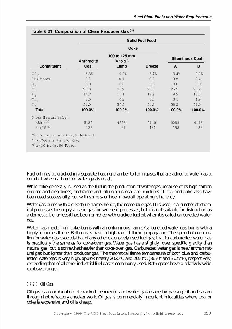
7/17/2019 Steel Plants Fuels and Water Consumption
http://slidepdf.com/reader/full/steel-plants-fuels-and-water-consumption 45/102
Fuel oil may be cracked in a separate heating chamber to form gases that are added to water gas toenrich it when carburetted water gas is made.
While coke generally is used as the fuel in the production of water gas because of its high carboncontent and cleanliness, anthracite and bituminous coal and mixtures of coal and coke also havebeen used successfully, but with some sacrifice in overall operating efficiency.
Water gas burns with a clear blue flame; hence, the name blue gas. It is used in a number of chem-ical processes to supply a basic gas for synthetic processes, but it is not suitable for distribution asa domestic fuel unless it has been enriched with cracked fuel oil, when it is called carburetted watergas.
Water gas made from coke burns with a nonluminous flame. Carburetted water gas burns with ahighly luminous flame. Both gases have a high rate of flame propagation. The speed of combus-tion for water gas exceeds that of any other extensively used fuel gas; that for carburetted water gasis practically the same as for coke-oven gas. Water gas has a slightly lower specific gravity thannatural gas, but is somewhat heavier than coke-oven gas. Carburetted water gas is heavier than nat-ural gas but lighter than producer gas. The theoretical flame temperature of both blue and carbu-retted water gas is very high, approximately 2020°C and 2050°C (3670°and 3725°F), respectively,exceeding that of all other industrial fuel gases commonly used. Both gases have a relatively wideexplosive range.
6.4.2.3 Oil Gas
Oil gas is a combination of cracked petroleum and water gas made by passing oil and steamthrough hot refractory checker work. Oil gas is commercially important in localities where coal orcoke is expensive and oil is cheap.
Steel Plant Fuels and Water Requirements
C opyright © 1999, The A IS E S teel Foundation, Pittsburgh, PA . A ll rights reserved. 323
Table 6.21 Composition of Clean Producer Gas (a)
Solid Fuel Feed
Coke
Bituminous Coal100 to 125 mmAnthracite (4 to 5)
Constituent Coal Lump Breeze A B
C O 2 6.3% 9.2% 8.7% 3.4% 9.2%
Illum inants 0.0 0.1 0.0 0.8 0.4
O 2 0.0 0.0 0.0 0.0 0.0
C O 25.0 21.9 23.3 25.3 20.9
H 2 14.2 11.1 12.8 9.2 15.6
C H 4 0.5 0.2 0.4 3.1 1.9
N 2 54.0 57.5 54.8 58.2 52.0
Total 100.0% 100.0% 100.0% 100.0% 100.0%
G ross H eating Value,
kJ/m 3(b) 5185 4753 5146 6088 6128
B tu/ft3(c) 132 121 131 155 156
(a)U .S. B ureau of M ines, B ulletin 301.(b)A t 760 m m H g, 0°C , dry.(c)A t 30 in. H g, 60°F, dry.
7/17/2019 Steel Plants Fuels and Water Consumption
http://slidepdf.com/reader/full/steel-plants-fuels-and-water-consumption 46/102
6.4.2.4 Liquefi ed Petr oleum Gas
Liquefied petroleum gases (LPG), sometimes referred to as bottled gases, have become commer-cially important because of the concentration of fuel energy in liquid form which may be convertedeasily into a gas. They are distributed for household use in steel cylinders, called bottles, and intank cars or trucks for industrial purposes. They are sometimes sold under various trade names but
are composed mainly of butane, propane, and pentane. A steel cylinder of propane as sold fordomestic purposes contains approximately 50,300 kilojoules per kilogram (21,640 Btu per pound)of liquid gas. Larger versions of these containers have been used by the steel industry as back upsupply for natural gas systems.
6.4.2.5 Alternative Fuel Sources
Drastic escalation of oil prices by the Organization of Petroleum Exporting Countries (OPEC) inthe 1970s stimulated interest in alternative sources of fuels to supplement existing supplies. Anumber of projects began operation during the early 1980s. Tennessee Eastman built a coal gasifi-cation plant to provide synthetic gas for conversion to chemicals. The Cool Water Project inCalifornia integrated coal gasif ication with the generation of electricity by a combination of gas
and steam turbines. Union Oil Company began operation of a shale oil facility at Parachute,Colorado, and a consortium built the Great Plains Coal gasification plant to produce synthetic nat-ural gas. Companies also started to recover gas from sanitary landfills.
Once oil and gas prices stabilized at more normal levels, many of these projects became uneco-nomic. Over time, these types of alternative fuel sources may once again become economicallyattractive.
6.4.3 Byproduct Gaseous Fuels The two major byproduct gaseous fuels recovered by the steel works are blast-furnace and coke-
oven gases. A number of other unavoidable gaseous fuels are created by regular manufacturingprocesses. Some of these are of minor economic consequence, but the majority are useful and gen-erally utilized at the plant where they are produced. An exception is oil-refinery gas which is some-times piped and marketed to industries adjacent to refineries. The calorific value and flamecharacteristics of byproduct gases have wide ranges. Blast-furnace gas has probably the lowest heatcontent of any, and oil refinery gas the highest, respectively about 3535 and 72,668 kilojoules percubic metre (90 and 1850 Btu per cubic foot), although both vary from these values.
6.4.3.1 Blast-Furnace Gas
Blast-furnace gas is a byproduct of the iron blast furnace. The paramount objective in blast-furnaceoperation is to produce iron of a specified quality, economically; the fact that usable gas issuesfrom the top of the furnace is merely a fortunate attendant circumstance. When air enters the tuy-eres, its oxygen reacts with the coke. The resulting gas passes up through the shaft of the furnacewhich has been charged with coke, ore, and limestone, and after a number of chemical reactionsand a travel of some 25 metres (80 feet), issues as a heated, dust-laden, lean, combustible gas. Theannual volume production of this gas is greater than that of any other gaseous fuel. Two and one-half to three and one-half tons of blast-furnace gas are generated per ton of pig iron produced.While the purpose of the gases generated by the partial combustion of carbon is to reduce iron ore,the value of a blast furnace as a gas producer is evident from the relation just noted.
The percentage of CO and CO2 in blast-furnace gas is directly related to the amount of carbon inthe coke and the amount of CO2 in the limestone charged per ton of iron produced. The rate of car-
bon consumption depends principally upon the kind of iron to be made, the physical and chemicalcharacteristics of the charged material, the distribution of the material in the furnace stack, the fur-nace lines, and the temperature of the hot blast. The total COCO2 content of the top gas isapproximately 40% by volume, and when producing ordinary grades of iron the ratio of CO to CO2
Ironmaking Volume
324 C opyright © 1999, The A IS E S teel Foundation, Pittsburgh, PA . A ll rights reserved.
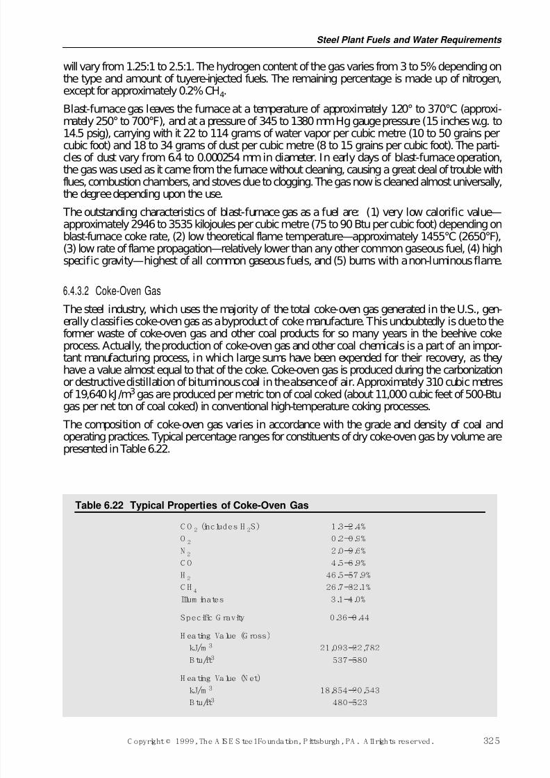
7/17/2019 Steel Plants Fuels and Water Consumption
http://slidepdf.com/reader/full/steel-plants-fuels-and-water-consumption 47/102
will vary from 1.25:1 to 2.5:1. The hydrogen content of the gas varies from 3 to 5% depending onthe type and amount of tuyere-injected fuels. The remaining percentage is made up of nitrogen,except for approximately 0.2% CH4.
Blast-furnace gas leaves the furnace at a temperature of approximately 120° to 370°C (approxi-mately 250°to 700°F), and at a pressure of 345 to 1380 mm Hg gauge pressure (15 inches w.g. to
14.5 psig), carrying with it 22 to 114 grams of water vapor per cubic metre (10 to 50 grains percubic foot) and 18 to 34 grams of dust per cubic metre (8 to 15 grains per cubic foot). The parti-cles of dust vary from 6.4 to 0.000254 mm in diameter. In early days of blast-furnace operation,the gas was used as it came from the furnace without cleaning, causing a great deal of trouble withflues, combustion chambers, and stoves due to clogging. The gas now is cleaned almost universally,the degree depending upon the use.
The outstanding characteristics of blast-furnace gas as a fuel are: (1) very low calorific value—approximately 2946 to 3535 kilojoules per cubic metre (75 to 90 Btu per cubic foot) depending onblast-furnace coke rate, (2) low theoretical flame temperature—approximately 1455°C (2650°F),(3) low rate of flame propagation—relatively lower than any other common gaseous fuel, (4) highspecific gravity—highest of all common gaseous fuels, and (5) burns with a non-luminous flame.
6.4.3.2 Coke-Oven Gas
The steel industry, which uses the majority of the total coke-oven gas generated in the U.S., gen-erally classifies coke-oven gas as a byproduct of coke manufacture. This undoubtedly is due to theformer waste of coke-oven gas and other coal products for so many years in the beehive cokeprocess. Actually, the production of coke-oven gas and other coal chemicals is a part of an impor-tant manufacturing process, in which large sums have been expended for their recovery, as theyhave a value almost equal to that of the coke. Coke-oven gas is produced during the carbonizationor destructive distillation of bituminous coal in the absence of air. Approximately 310 cubic metresof 19,640 kJ/m3gas are produced per metric ton of coal coked (about 11,000 cubic feet of 500-Btu
gas per net ton of coal coked) in conventional high-temperature coking processes. The composition of coke-oven gas varies in accordance with the grade and density of coal andoperating practices. Typical percentage ranges for constituents of dry coke-oven gas by volume arepresented in Table 6.22.
Steel Plant Fuels and Water Requirements
C opyright © 1999, The A IS E S teel Foundation, Pittsburgh, PA . A ll rights reserved. 325
Table 6.22 Typical Properties of Coke-Oven Gas
C O 2 (includes H 2S) 1.3–2.4%
O 2 0.2–0.9%
N 2 2.0–9.6%
C O 4.5–6.9%
H 2 46.5–57.9%
C H 4 26.7–32.1%
Illum inates 3.1–4.0%
Specific G ravity 0.36–0.44
H eating Value (G ross)
kJ/m 3 21,093–22,782
B tu/ft3 537–580
H eating Value (N et)kJ/m 3 18,854–20,543
B tu/ft3 480–523
7/17/2019 Steel Plants Fuels and Water Consumption
http://slidepdf.com/reader/full/steel-plants-fuels-and-water-consumption 48/102
Coke-oven gas contains hydrogen sulf ide, H2S. Approximately 40% of the sulfur in coal, notremoved in the washing process, is evolved with the distillation products. Much of this remains inthe gas. Carbonization of coals containing 1.20% sulfur evolves a gas containing approximately 9.7grams of sulfur per cubic metre (424 grains per 100 cubic feet), and those containing 1.60% sul-fur approximately 14 grams of sulfur per cubic metre (600 grains per 100 cubic feet). Commercialcoals in the eastern part of the U.S. usually run from 0.5 to 1.5% sulfur. Gases high in sulfur con-
tent are very undesirable for metallurgical purposes.
Coke-oven gas normally is saturated with water vapor. In distribution systems, means must be pro-vided for draining off the condensation due to any temperature change.
Coke-oven gas burns with a non-luminous to semi-luminous flame, depending upon the degree of mixing air and gas. Its rate of flame propagation is high, considerably higher than natural, pro-ducer, or blast-furnace gas. It has a low specific gravity, in fact the lowest of any of the gaseousfuels commonly utilized by the steel industry. It has a high theoretical flame, approximately1980°C (3600°F), which is a little higher than that of natural gas. The explosive range is roughlytwice that of natural gas.
6.4.3.3 Basic Oxygen Furnace GasOne fuel that has not been economically recovered by the domestic steel industry is basic oxygenfurnace gas. The utilization of this fuel requires special collection and cleaning equipment whichwould allow for its use in the steel plant. The special equipment includes such items as anadjustable skirt on the vessel hood, a flare, a gas holder, by-pass valving and a wet electrical pre-cipitator. BOF gas of sufficient quality to be used is collected only during part of the blowing cycle.For example, the start of gas recovery begins when the CO content is above 30% and the O2 con-tent falls below 2%. The stoppage of gas recovery occurs when the O2 content is above 2% or theCO content falls below 30%. These parameters may vary from plant to plant. The composition of the gas varies throughout the blow but a typical analysis ( by volume) is as follows: 57% CO, 26%CO2, 2% H2O, 15% N2, and O2 <1% (most of the cycle).
In steel plants in other countries which utilize BOF gas, the most predominate use is in the boilerplant, either directly or blended with blast-furnace gas. More recently, BOF gas has also been uti-lized along with blast-furnace gas in gas turbine combined cycle units, which are much more effi-cient in producing power than a conventional boiler and steam turbine generator set.
6.4.4 Uses for Various Gaseous Fuels in the Steel IndustryGaseous fuels are ideal for many steel plant applications. Below are the more important applica-tions where gaseous fuels either must be used because of the nature of the work or facility, or wherethey are preferred over liquid or solid fuel:
•Coke-Oven Heating•Blast-Furnace Stoves•Gas Turbines for Power Generation•Boilers•Soaking Pits•Reheating Furnaces•Forge and Blacksmith Furnaces•Normalizing and Annealing Furnaces•Controlled-Cooling Pits•Foundry Core Ovens•Blast Furnace and Steel Ladle Drying
•Drying of Blast-Furnace Runners•Hot-Top Drying•Ladle Preheating•Oxy-Fuel Burners
Ironmaking Volume
326 C opyright © 1999, The A IS E S teel Foundation, Pittsburgh, PA . A ll rights reserved.
7/17/2019 Steel Plants Fuels and Water Consumption
http://slidepdf.com/reader/full/steel-plants-fuels-and-water-consumption 49/102
The choice of the most desirable fuel for each of the many facilities in a steel plant is not alwayspossible, but by judicious planning the most efficient fuel or combination can be selected fromthose available. The general characteristics of each gas govern, wherever possible, its selection fora specific purpose in a steel plant. An outline of the important applications of the major gaseousfuels follows.
6.4.4.1 Use of Blast-Furnace Gas
For many years the use of blast-furnace gas for purposes other than for the firing of stoves and boil-ers was not economical. A number of factors have contributed, however, to the enlarged use of blast-furnace gas, the more important of which are: (1) rising cost of purchased fuel; (2) technicalprogress in gas cleaning, in the use of regeneration and recuperation, and in the mixing of gaseousfuels; (3) the economic advantage of using pulverized coal in boiler houses to substitute for blast-furnace gas, thereby permitting its substitution elsewhere for the more expensive liquid andgaseous fuels; and (4) seasonal shortages in the availability of purchased liquid and gaseous fuels.
In certain applications, in addition to preheating the air, the gas itself may be preheated to providehigher temperature potential. For the facilities listed, blast-furnace gas may be utilized successfullywithout preheat: blast furnace stoves, soaking pits, normalizing and annealing furnaces, foundrycore ovens, gas engines for blowing or power generation, gas turbines for power generation, andboilers.
The thermal advantage of using blast-furnace gas in gas engines for blowing and for electric-powergeneration must overcome the heavy investment and maintenance expense of this equipment. Themodern boiler house utilizing high steam pressure and temperature with efficient turbo-blowersand generators has sufficiently reduced the thermal advantage of gas engines, such that their use isdifficult to justify. Some steel plants in Asia and Europe have been successful in the use of direct-connected gas turbines for driving generators.
Preheated blast-furnace gas burned with preheated air has been used successfully in coke-oven
heating, soaking pits, and reheating furnaces.
When blast-furnace gas is preheated, it should have a minimum cleanliness of 0.023 grams percubic metre (0.01 grains per cubic foot); and in all cases where this gas is used, extra precautionsmust be taken to prevent the escape of fuel or unburned gas into attendant surroundings because itcontains a large percentage of toxic CO gas. Blast-furnace gas is used for many applications in thesteel plant and, in addition, is used frequently for heating coke ovens and sometimes is mixed withother gases as a fuel. In blast furnace operations, where the blast-furnace gas has a heating valueapproaching a low value of 2946 kilojoules per cubic metre (75 Btu per cubic foot), it is necessaryto switch the gas with other fuels to obtain very high hot-blast temperature from the stove.
6.4.4.2 Use of Coke-Oven GasCoke-oven gas has had a more extended use than blast-furnace gas because of: (1) relatively lowdistribution costs due to its low specific gravity and high calorific value; (2) its ability to developextremely high temperatures by combustion; and (3) the high rate at which it can release heat,thereby eliminating excessively large combustion chambers. The low specific gravity of coke-ovengas is a disadvantage, and for this reason, it is supplemented wherever possible with a drivenliquid fuel. In addition, the sulfur (in the form of H2S) present in raw (not desulfurized) coke-ovengas is a distinct disadvantage, particularly in heating certain grades of alloy steel for rolling. Itspresence also requires the use of materials resistant to sulfur attack in pipelines, valves, andburners.
There are a number of fuel applications in a steel plant where neither blast-furnace gas nor coke-oven gas, when burned alone, develop the desired flame characteristics or temperature level foroptimum results. By mixing two fuels of such great variance in characteristics, a more ideal fuelcan be obtained for specific applications.
Steel Plant Fuels and Water Requirements
C opyright © 1999, The A IS E S teel Foundation, Pittsburgh, PA . A ll rights reserved. 327
7/17/2019 Steel Plants Fuels and Water Consumption
http://slidepdf.com/reader/full/steel-plants-fuels-and-water-consumption 50/102
The speed of combustion is very high for coke-oven gas and very low for blast-furnace gas. Thedesired speed can be attained through the proper proportioning of the two fuels. The speed also canbe modified to a limited extent when necessary by suitable combustion technique. Mixed blast-fur-nace and coke-oven gas is particularly suitable for application to soaking pits and reheating fur-naces.
6.4.4.3 Use of N atur al Gas
Due to plant balances requiring the purchase of outside gaseous fuels, mixtures of coke-oven gasand natural gas are often utilized. While the temperature-developing characteristics of these twogases are nearly identical, they have differences in other characteristics, notably in the rate of flamepropagation and in luminosity. By proper proportioning, the advantage of a short, intensive cuttingflame or a long, luminous, soft flame may be had to suit the applications. Use of natural gas forflame cutting and scarfing has been increasing steadily.
6.4.4.4 Use of Producer Gas
Raw, hot, producer gas was used extensively in the past in steel plant operations for open-hearth
furnaces, soaking pits, and reheating furnaces. It was customary to preheat this gas regenerativelywhen used in batch-type reheating furnaces. In continuous-type reheating furnaces, the fuel seldomwas preheated. With good gas making, producer gas develops a soft, heavy, long, luminous flamedesirable for reheating steel. The use of this gas has been superseded in all plants by natural gasand byproduct gaseous and liquid fuels.
6.4.5 Combustion of Various Gaseous Fuels The major combustion reactions of the components of gaseous fuels with air and a table of essen-tial gas combustion constants were given in Section 6.1.2.5. From chemical equations, the quan-tity of air required to provide perfect combustion and the resultant products may be calculated for
any given gaseous fuel. Table 6.23 shows the air requirements, products of combustion, and perti-nent characteristics of several gaseous fuels. The degree of mixing of air with a gaseous fuel, andthe degree of excess or deficiency of air to the theoretical requirements are pertinent combustionproblems. The degree of mixing is controlled by burner design. Burners have been developed toproduce short, intense flames or long, slow-burning flames. The short, intense flame is usuallynonluminous or semi-luminous, while the long flame is luminous. This relation is not always thecase, however, because a gas must contain hydrocarbons to develop luminosity. Burners capable of producing short, intense flames will liberate a large amount of heat in a small space. Some gases,due primarily to the constituents of which they are composed, are capable of a high rate of heatrelease; others, of a very low rate of heat release. The two extremes are evident in two commonsteel-plant fuels, coke-oven gas and blast-furnace gas, which give high and low rates of heat
release, respectively. There is also a limit to the length of flame which can be produced. It is deter-mined by the ability of the flame to provide enough heat to propagate itself. If the short, intense-flame type burner is used with coke-oven or natural gas, combustion will be so intense that noflame will be visible, and heat can be liberated at rates over 40 million watts per cubic metre perhour (up to several million Btu per cubic foot per hour) of combustion space; while the long, slow-burning-flame burner firing the same gases is capable of developing a visible flame 6 to 9 metres(20 to 30 feet) long with a heat liberation of 155,000 to 210,000 watts per cubic metre (15,500 to21,000 Btu per cubic foot per hour). Both types of flames are desirable for specific steel plantapplications. It is obvious that burner selection based on degree of mixing is important. Carryingan excess or deficiency of air for combustion is practiced usually to control scale formation, butthis is done sometimes to control flame characteristics. An excess of air tends to shorten, while a
deficiency lengthens, a flame. An excess of air above theoretical requirements causes higher heatlosses as any extra air absorbs its share of the heat of combustion. Fuels containing hydrogen musthave the exit stack temperature high enough to avoid condensation of water within the furnace sys-tem and subsequent corrosion of furnace parts. In some cases, it is necessary to burn the fuel with
Ironmaking Volume
328 C opyright © 1999, The A IS E S teel Foundation, Pittsburgh, PA . A ll rights reserved.
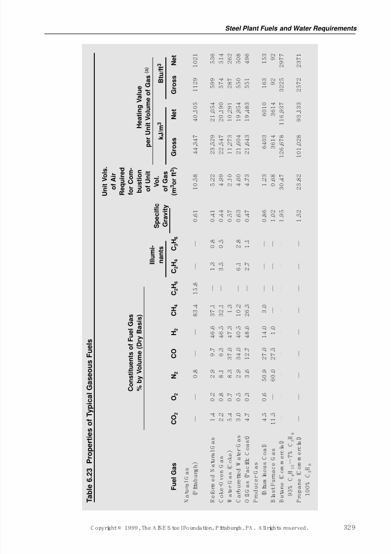
7/17/2019 Steel Plants Fuels and Water Consumption
http://slidepdf.com/reader/full/steel-plants-fuels-and-water-consumption 51/102
Steel Plant Fuels and Water Requirements
C opyright © 1999, The A IS E S teel Foundation, Pittsburgh, PA . A ll rights reserved. 329
T a b l e
6 . 2 3
P r o p e r t i e s o f T y p i c a l G
a s e o u s F u e l s
U
n i t V o l s .
o f A i r
R
e q u i r e d
C
o n s t i t u e n t s o f F u e l G a s
f o r C o m -
%
b y V o l u m e ( D r y B a s i s )
b u s t i o n
H e a t i n g V a
l u e
o f U n i t
p e r U n i t V o l u m e o f G a s ( a )
I l l u m i -
S p e c i f i c
V o l .
n a n t s
G r a v i t y
o f G a s
k J / m 3
B t u / f t 3
F u
e l G a s
C O 2
O 2
N 2
C O
H 2
C H 4
C 2 H 6
C 2 H 4
C 3 H 6
( m 3 o r f t 3 )
G r o s s
N e t
G r o s s
N e t
N a
t u r a
l G a s
( P i t t s
b u r g
h )
—
—
0 . 8
—
—
8 3 . 4
1 5 . 8
—
—
0 . 6
1
1 0 . 5
8
4 4 , 3
4 7
4 0 , 1
0 5
1 1 2 9
1 0 2 1
R e
f o r m
e d N a
t u r a
l G a s
1 . 4
0 . 2
2 . 9
9 . 7
4 6 . 6
3 7 . 1
—
1 . 3
0 . 8
0 . 4
1
5 . 2
2
2 3 , 5
2 9
2 1 , 0
5 4
5 9 9
5 3 6
C o
k e - O v e n
G a s
2 . 2
0 . 8
8 . 1
6 . 3
4 6 . 5
3 2 . 1
—
3 . 5
0 . 5
0 . 4
4
4 . 9
9
2 2 , 5
4 7
2 0 , 1
9 0
5 7 4
5 1 4
W a
t e r
G a s
( C o
k e
)
5 . 4
0 . 7
8 . 3
3 7 . 0
4 7 . 3
1 . 3
—
—
—
0 . 5
7
2 . 1
0
1 1 , 2
7 3
1 0 , 2
9 1
2 8 7
2 6 2
C a r b u r e
t t e d W a
t e r
G a s
3 . 0
0 . 5
2 . 9
3 4 . 0
4 0 . 5
1 0 . 2
—
6 . 1
2 . 8
0 . 6
3
4 . 6
0
2 1 , 6
0 4
1 9 , 9
5 4
5 5 0
5 0 8
O i l G a s
( P a c
i f i c C o a s
t )
4 . 7
0 . 3
3 . 6
1 2 . 7
4 8 . 6
2 6 . 3
—
2 . 7
1 . 1
0 . 4
7
4 . 7
3
2 1 , 6
4 3
1 9 , 4
8 3
5 5 1
4 9 6
P r o
d u c e r
G a s
( B i t u
m i n o u s
C o a
l )
4 . 5
0 . 6
5 0 . 9
2 7 . 0
1 4 . 0
3 . 0
—
—
—
0 . 8
6
1 . 2
3
6 4 0 3
6 0 1 0
1 6 3
1 5 3
B l a s t F
u r n a c e
G a s
1 1 . 5
—
6 0 . 0
2 7 . 5
1 . 0
—
—
—
—
1 . 0
2
0 . 6
8
3 6 1 4
3 6 1 4
9 2
9 2
B u
t a n e
( C o m m e r c
i a l )
—
—
—
—
—
—
—
—
—
1 . 9
5
3 0 . 4
7
1 2 6 , 6
7 8
1 1 6 , 9
3 7
3 2 2 5
2 9 7 7
9 3 %
C 4
H 1 0 —
7 %
C 3
H 8
P r o p a n e
( C o m m e r c
i a l )
—
—
—
—
—
—
—
—
—
1 . 5
2
2 3 . 8
2
1 0 1 , 0
2 8
9 3 , 1
3 3
2 5 7 2
2 3 7 1
1 0 0 %
C 3
H 8
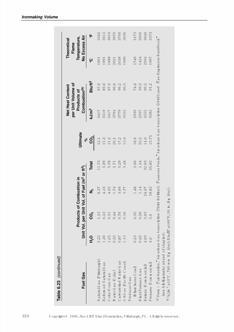
7/17/2019 Steel Plants Fuels and Water Consumption
http://slidepdf.com/reader/full/steel-plants-fuels-and-water-consumption 52/102
Ironmaking Volume
330 C opyright © 1999, The A IS E S teel Foundation, Pittsburgh, PA . A ll rights reserved.
T a b l e
6 . 2 3
( c o n t i n u e d )
N e t H e a t C o n t e n t
T
h e o r e t i c a l
p
e r U n i t V o l u m e o f
F l a m e
P r o d u c t s o f C o m b u s t i o n i n
P r o d u c t s o f
T e
m p e r a t u r e ,
F u e l G a s
U n i t V o l . p e r U n i t V o l . o f F u e l ( m 3 o r f t 3 )
U l t i m a t e
C o m b u s t i o n ( b )
N o
E x c e s s A i r
%
H 2 O
C O 2
N 2
T o t a l
C O 2
k J
/ m 3
B t u / f t 3
° C
° F
N a
t u r a
l G a s
( P i t t s b u r g
h )
2 . 2
2
1 . 1
5
8 . 3
7
1 1 . 7
3
1 2 . 1
3 4 1 7
8 7 . 0
1 9 6 1
3 5 6 2
R e
f o r m
e d N a
t u r a
l G a s
1 . 3
0
0 . 5
3
4 . 1
6
5 . 9
9
1 1 . 3
3 5 1 9
8 9 . 6
1 9 9 1
3 6 1 5
C o
k e - O v e n
G a s
1 . 2
5
0 . 5
1
4 . 0
2
5 . 7
8
1 1 . 2
3 4 1 7
8 7 . 0
1 9 8 8
3 6 1 0
W a
t e r
G a s
( C o
k e
)
0 . 5
3
0 . 4
4
1 . 7
4
2 . 7
1
2 0 . 1
3 7 9 4
9 6 . 6
2 0 2 1
3 6 7 0
C a r b u r e
t t e d W a
t e r
G a s
0 . 8
7
0 . 7
6
3 . 6
6
5 . 2
9
1 7 . 2
3 7 7 9
9 6 . 2
2 0 3 8
3 7 0 0
O i l G a s
( P a c
i f i c C o a s
t )
1 . 1
5
0 . 5
6
3 . 7
7
5 . 4
8
1 2 . 9
3 5 5 5
9 0 . 5
1 9 9 9
3 6 3 0
P r o
d u c e r
G a s
( B i t u
m i n o u s
C o a
l )
0 . 2
3
0 . 3
5
1 . 4
8
2 . 0
6
1 8 . 9
2 9 3 0
7 4 . 6
1 7 4 6
3 1 7 5
B l a s t F
u r n a c e
G a s
0 . 0
2
0 . 3
9
1 . 1
4
1 . 5
4
2 5 . 5
2 3 3 7
5 9 . 5
1 4 5 4
2 6 5 0
B u
t a n e
( C o m m e r c
i a l )
4 . 9
3
3 . 9
3
2 4 . 0
7
3 2 . 9
3
1 4 . 0
3 5 5 5
9 0 . 5
2 0 0 4
3 6 4 0
P r o p a n e
( C o m m e r c
i a l )
4 . 0
3 . 0
1 8 . 8
2
2 5 . 8
2
1 3 . 7
5
3 5 8 2
9 1 . 2
1 9 6 7
3 5 7 3
( a ) F r o m
: “ C o m
b u s
t i o n , ”
A m e r i c a n
G a s A
s s o c
i a t i o n
( T h i r d E d i t i o n
) ; “ G a s e o u s
F u e
l s , ”
A m e r i c a n
G a s
A s s o c i a
t i o n
( 1 9 4 8 ) ; a n
d “ G a s
E n g
i n e e r s
H a n
d b o o
k ”
( s e e
b i b l i o g r a p
h y a
t e n
d o
f c
h a p
t e r ) .
( b ) k J / m
3 a
t 0 ° C ,
7 6 0 m m
H g
( d r y
) ; B t u / f t 3 a
t 6 0 ° F , 3 0 i n .
H g
( d r y
) .
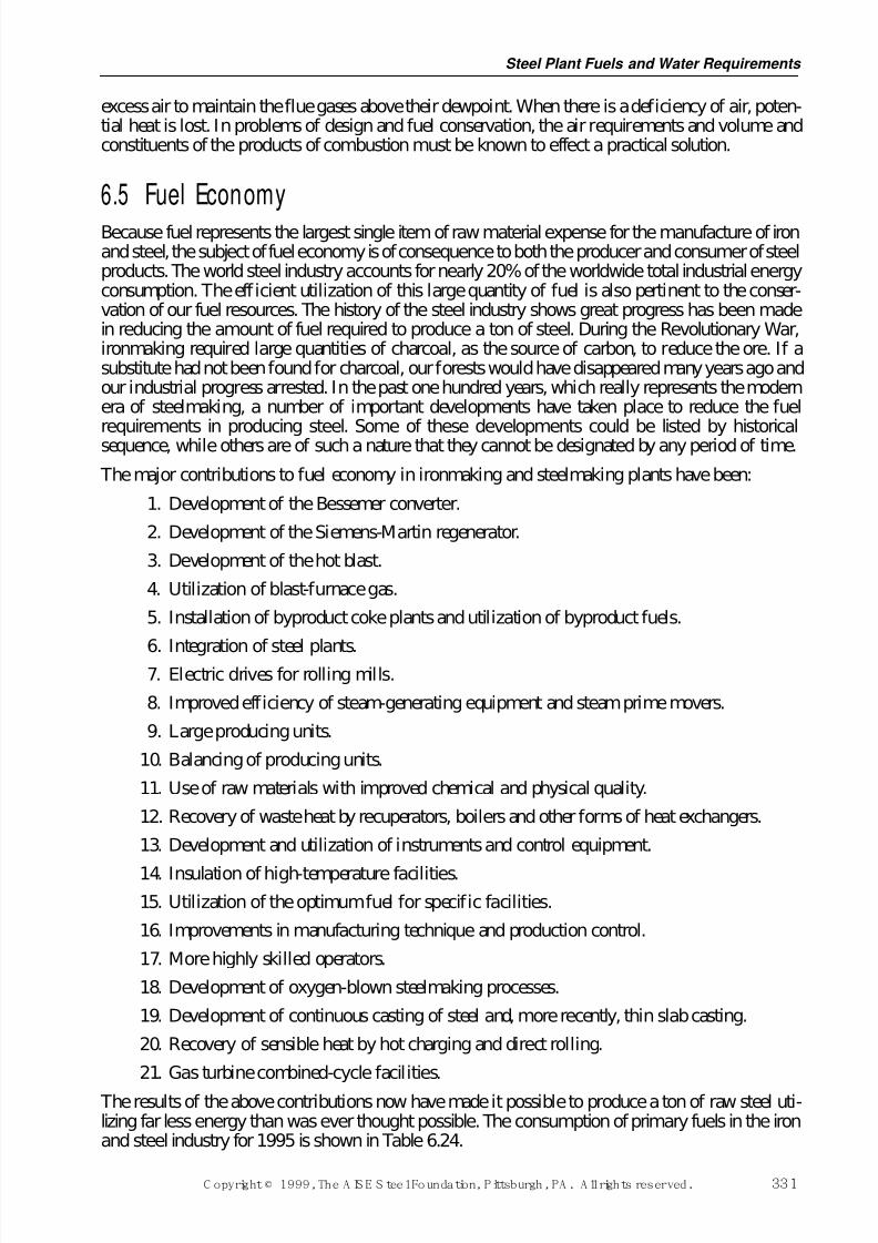
7/17/2019 Steel Plants Fuels and Water Consumption
http://slidepdf.com/reader/full/steel-plants-fuels-and-water-consumption 53/102
excess air to maintain the flue gases above their dewpoint. When there is a deficiency of air, poten-tial heat is lost. In problems of design and fuel conservation, the air requirements and volume andconstituents of the products of combustion must be known to effect a practical solution.
6.5 Fuel EconomyBecause fuel represents the largest single item of raw material expense for the manufacture of ironand steel, the subject of fuel economy is of consequence to both the producer and consumer of steelproducts. The world steel industry accounts for nearly 20% of the worldwide total industrial energyconsumption. The efficient utilization of this large quantity of fuel is also pertinent to the conser-vation of our fuel resources. The history of the steel industry shows great progress has been madein reducing the amount of fuel required to produce a ton of steel. During the Revolutionary War,ironmaking required large quantities of charcoal, as the source of carbon, to reduce the ore. If asubstitute had not been found for charcoal, our forests would have disappeared many years ago andour industrial progress arrested. In the past one hundred years, which really represents the modernera of steelmaking, a number of important developments have taken place to reduce the fuel
requirements in producing steel. Some of these developments could be listed by historicalsequence, while others are of such a nature that they cannot be designated by any period of time.
The major contributions to fuel economy in ironmaking and steelmaking plants have been:
1. Development of the Bessemer converter.
2. Development of the Siemens-Martin regenerator.
3. Development of the hot blast.
4. Utilization of blast-furnace gas.
5. Installation of byproduct coke plants and utilization of byproduct fuels.
6. Integration of steel plants.7. Electric drives for rolling mills.
8. Improved efficiency of steam-generating equipment and steam prime movers.
9. Large producing units.
10. Balancing of producing units.
11. Use of raw materials with improved chemical and physical quality.
12. Recovery of waste heat by recuperators, boilers and other forms of heat exchangers.
13. Development and utilization of instruments and control equipment.
14. Insulation of high-temperature facilities.15. Utilization of the optimum fuel for specific facilities.
16. Improvements in manufacturing technique and production control.
17. More highly skilled operators.
18. Development of oxygen-blown steelmaking processes.
19. Development of continuous casting of steel and, more recently, thin slab casting.
20. Recovery of sensible heat by hot charging and direct rolling.
21. Gas turbine combined-cycle facilities.
The results of the above contributions now have made it possible to produce a ton of raw steel uti-lizing far less energy than was ever thought possible. The consumption of primary fuels in the ironand steel industry for 1995 is shown in Table 6.24.
Steel Plant Fuels and Water Requirements
C opyright © 1999, The A IS E S teel Foundation, Pittsburgh, PA . A ll rights reserved. 331
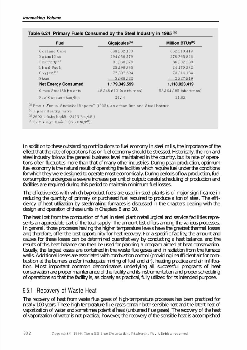
7/17/2019 Steel Plants Fuels and Water Consumption
http://slidepdf.com/reader/full/steel-plants-fuels-and-water-consumption 54/102
In addition to these outstanding contributions to fuel economy in steel mills, the importance of theeffect that the rate of operations has on fuel economy should be stressed. Historically, the iron andsteel industry follows the general business level maintained in the country, but its rate of opera-tions often fluctuates more than that of many other industries. During peak production, optimumfuel economy is the natural result of operating the facilities which require fuel under the conditionsfor which they were designed to operate most economically. During periods of low production, fuelconsumption undergoes a severe increase per unit of output; careful scheduling of production and
facilities are required during this period to maintain minimum fuel losses.
The effectiveness with which byproduct fuels are used in steel plants is of major significance inreducing the quantity of primary or purchased fuel required to produce a ton of steel. The effi-ciency of heat utilization by steelmaking furnaces is discussed in the chapters dealing with thedesign and operation of these units in Chapters 8 and 10.
The heat lost from the combustion of fuel in steel plant metallurgical and service facilities repre-sents an appreciable part of the total supply. The amount lost differs among the various processes.In general, those processes having the higher temperature levels have the greatest thermal lossesand, therefore, offer the best opportunity for heat recovery. For a specific facility, the amount andcauses for these losses can be determined quantitatively by conducting a heat balance, and the
results of this heat balance can then be used for planning a program aimed at heat conservation.Usually, the largest losses are contained in the waste flue gases and in radiation from the furnacewalls. Additional losses are associated with combustion control (providing insufficient air for com-bustion at the burners and/or inadequate mixing of fuel and air), heating practice and air infiltra-tion. Most important common denominators underlying all successful programs of heatconservation are proper maintenance of the facility and its instrumentation and proper schedulingof operations so that the facility is, as closely as practical, fully utilized for its intended purpose.
6.5.1 Recovery of Waste Heat The recovery of heat from waste flue gases of high-temperature processes has been practiced for
nearly 100 years. These high-temperature flue gases contain both sensible heat and the latent heat of vaporization of water and sometimes potential heat (unburned flue gases). The recovery of the heatof vaporization of water is not practical; however, the recovery of the sensible heat is accomplished
Ironmaking Volume
332 C opyright © 1999, The A IS E S teel Foundation, Pittsburgh, PA . A ll rights reserved.
Table 6.24 Primary Fuels Consumed by the Steel Industry in 1995 (a)
Fuel Gigajoules(b) Million BTUs(b)
C oal and C oke 688,302,130 652,510,419
N atural G as 294,056,779 278,765,826
Electricity(c) 91,068,079 86,332,539Liquid Fuels 25,496,395 24,170,582
O xygen(d) 77,337,694 73,316,134
Steam 3,088,522 2,927,919
Net Energy Consumed 1,179,349,599 1,118,023,419
G ross Steel Shipm ents 48,248,612 (m etric tons) 53,194,095 (short tons)
Fuel C onsum ption/Ton 24.44 21.02
(a) From : “Annual Statistical R eports”(1995), A m erican Iron and Steel Institute(b)H igher H eating Valve(c) 3600 K ilojoules/kW (3413 B tu/kW )(d)
37.2 K ilojoules/m3
(175 B tu/ft3
)
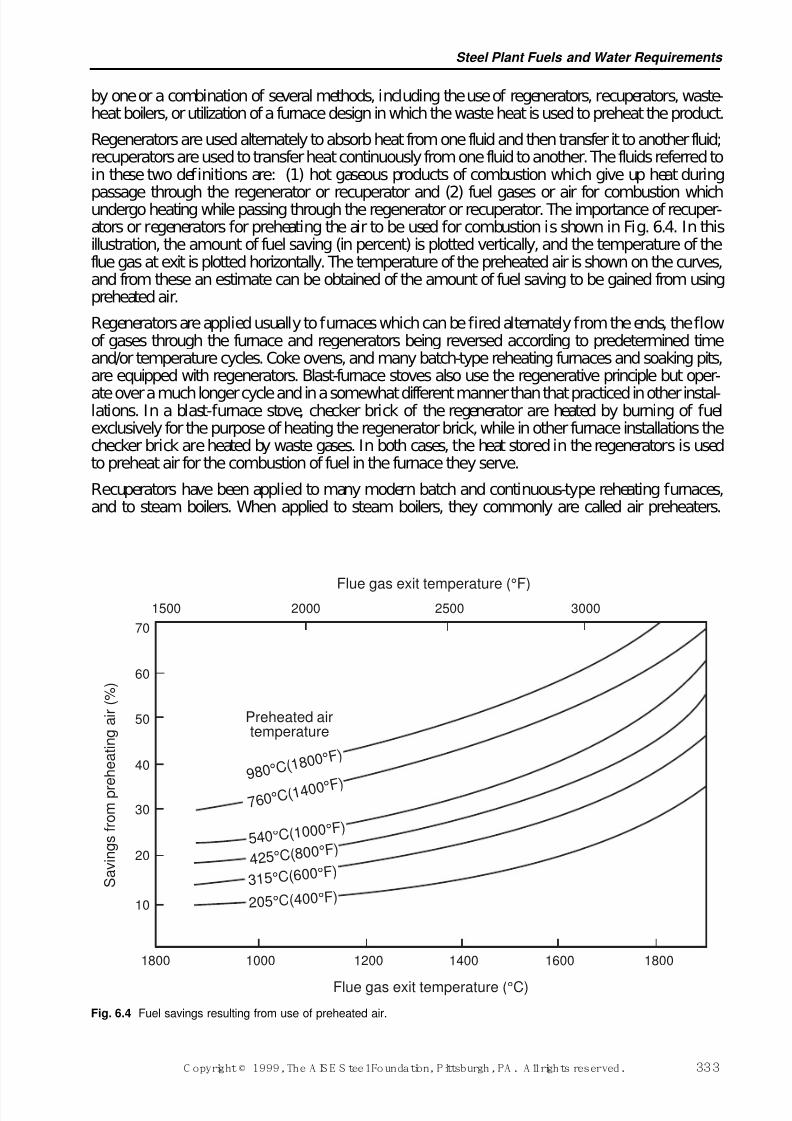
7/17/2019 Steel Plants Fuels and Water Consumption
http://slidepdf.com/reader/full/steel-plants-fuels-and-water-consumption 55/102
by one or a combination of several methods, including the use of regenerators, recuperators, waste-heat boilers, or utilization of a furnace design in which the waste heat is used to preheat the product.
Regenerators are used alternately to absorb heat from one fluid and then transfer it to another fluid;recuperators are used to transfer heat continuously from one fluid to another. The fluids referred toin these two definitions are: (1) hot gaseous products of combustion which give up heat during
passage through the regenerator or recuperator and (2) fuel gases or air for combustion whichundergo heating while passing through the regenerator or recuperator. The importance of recuper-ators or regenerators for preheating the air to be used for combustion is shown in Fig. 6.4. In thisillustration, the amount of fuel saving (in percent) is plotted vertically, and the temperature of theflue gas at exit is plotted horizontally. The temperature of the preheated air is shown on the curves,and from these an estimate can be obtained of the amount of fuel saving to be gained from usingpreheated air.
Regenerators are applied usually to furnaces which can be fired alternately from the ends, the flowof gases through the furnace and regenerators being reversed according to predetermined timeand/or temperature cycles. Coke ovens, and many batch-type reheating furnaces and soaking pits,are equipped with regenerators. Blast-furnace stoves also use the regenerative principle but oper-
ate over a much longer cycle and in a somewhat different manner than that practiced in other instal-lations. In a blast-furnace stove, checker brick of the regenerator are heated by burning of fuelexclusively for the purpose of heating the regenerator brick, while in other furnace installations thechecker brick are heated by waste gases. In both cases, the heat stored in the regenerators is usedto preheat air for the combustion of fuel in the furnace they serve.
Recuperators have been applied to many modern batch and continuous-type reheating furnaces,and to steam boilers. When applied to steam boilers, they commonly are called air preheaters.
Steel Plant Fuels and Water Requirements
C opyright © 1999, The A IS E S teel Foundation, Pittsburgh, PA . A ll rights reserved. 333
70
60
50
40
30
20
10
S a v i n g s f r o m p r e h e a t i n g a i r ( % )
1800 1000 1200 1400 1600 1800
Flue gas exit temperature (°C)
1500 2000 2500 3000Flue gas exit temperature (°F)
Preheated airtemperature
9 8 0 ° C( 1 8 0 0 ° F )
5 40 °C(1000 °F )
7 6 0 ° C( 1 4 0 0 ° F )
4 25 °C( 800 °F )
315 °C(600 °F )
205°C(400°F )
Fig. 6.4 Fuel savings resulting from use of preheated air.
7/17/2019 Steel Plants Fuels and Water Consumption
http://slidepdf.com/reader/full/steel-plants-fuels-and-water-consumption 56/102
Recuperators are of three general types, classified according to the direction of flow of the wastegases and air, as follows: counter-flow, parallel or co-current flow, and cross-flow.
Counter-flow is used to attain maximum air-preheat temperatures, and cross-current flow is usedto secure optimum heat-transfer rates (kilojoules per square metre of recuperator surface perdegree Celsius temperature difference per hour, or Btu per square foot of recuperator surface per
degree Fahrenheit temperature difference per hour). Parallel flow is used where it is necessary, suchas in metallic recuperators, to maintain the temperature difference of the division wall between thetwo fluids as uniform as possible throughout its length and to keep the temperature of the hot endbelow a maximum so that the metallic elements will not be overheated. Generally, a combinationof counter-flow and cross-flow is applied to many steel-mill furnace applications where a refrac-tory material is used to divide the two fluids. A combination of the two types is accomplished bybaffling the flow of one of the fluids. In such designs, the general direction of flow of fluidsexchanging heat is counter-current and the flow in each baffle is cross-current. When the temper-ature of waste gas from which heat is to be extracted is relatively low, under 980°C (approximately1800°F), metallic tubes (e.g., stainless steel) are generally used because they possess an advantageagainst leakage. Higher-temperature recuperators are generally constructed of clay or silicon-car-
bide materials; often, however, these recuperators suffer the disadvantage of air leakage.Waste-heat boilers are used to obtain heat recovery when a practical limit of recovery has beenobtained by regenerators or recuperators and there is still sufficient heat left in the waste gases to justify expenditures for the waste-heat boilers. Boilers sometimes are used in place of regeneratorsor recuperators, depending upon conditions such as where preheated air is undesirable or where thegeneration of steam solves the problem of fuel conservation more satisfactorily. Waste-heat boilersare most applicable to high-temperature, continuous processes and have been used principally inthe steel plant in conjunction with basic oxygen vessels, gas turbines and, to a lesser degree, withreheating furnaces and soaking pits. Fire-tube and water-tube boiler types have been installed, theformer being the preferred type and generally of horizontal single-pass design. Waste-heat boilersusually are provided with superheaters and sometimes with economizers.
6.5.2 M inim izing Radiati on LossesRadiation losses from the walls and roofs of the furnaces can be minimized by the selection anduse of an insulating system. Thermal insulating materials have been used in steel plants for a greatmany years. There are many different kinds of insulating materials, each being most suitable for aspecific temperature level and for the degree of insulation desired and improvements in insulatingmaterials are continuing. A detailed discussion of insulating systems for steel-mill furnaces isgiven in Section 3.6.3.
6.5.3 Combust ion Contr olAs mentioned previously, one of the large losses in a heating process is the heat contained in thewaste flue gases. The amount of sensible heat in the waste flue gases is the product of the heat con-tent per unit volume (m3 or ft3) or unit weight (kg or lbm) of gas multiplied by the total volume ortotal weight of the gas respectively, in the appropriate units. The total loss of heat in waste fluegases can be minimized by providing the proper amount of air for combustion. If too much air isprovided, the volume of the waste gases is increased. In addition, an excess of air over that requiredfor combustion lowers the flame temperature and increases the time necessary to heat the product.In a similar manner, an excess of fuel (or a deficiency of air) also decreases the flame temperatureand prolongs the heating time and, in addition, results in unburned fuel being carried into the wasteflue gases. This results in unnecessary usage of fuel and can be dangerous because this unburnedfuel can burn in the flue and cause damage to the stack and/or waste heat recovery systems. In other
words, fuel economy is optimized by the use of proper combustion conditions.
In modern steel plant furnaces, and in boilers, the amount of air supplied for combustion is main-tained only a little above theoretical requirements by special pressure regulators and valves which
Ironmaking Volume
334 C opyright © 1999, The A IS E S teel Foundation, Pittsburgh, PA . A ll rights reserved.
7/17/2019 Steel Plants Fuels and Water Consumption
http://slidepdf.com/reader/full/steel-plants-fuels-and-water-consumption 57/102
accurately proportion the amounts of fuel and air fed to the burners. For most burners, an amountof air approximately 10% above theoretical is considered to be optimum. The use of instrumentsto continuously monitor the products of combustion and automatically control the air-fuel ratio toachieve this desired level of excess air has led to improved fuel economy and heating efficiency.
The amount of waste flue gases can be minimized, and the heating rate of the unit can be increased,
by the oxygen enrichment of combustion air. Air is composed of only approximately 20.9% oxy-gen (by volume), with the remainder consisting of inert nitrogen plus a small amount of severalother inert gases. When combustion takes place, the oxygen combines with the carbon and hydro-gen of the fuel and liberates heat. The inert gases of the air absorb heat from the combustion andcarry it out of the furnace, and it is lost so far as the furnace process is concerned. These gasesreduce flame temperature by absorbing heat, thus reducing the rate of transfer of heat to the work.
Obviously, if the inert content of the air could be diminished, more efficient combustion could beobtained. Recent technical developments that have lowered the cost for producing oxygen of com-mercial purity have made large-scale use of this gas economical for some industrial processes.Consequently, many plants have experimented with the addition of oxygen to ordinary air used forcombustion, with generally good results. In effect, increasing the oxygen content lowers the inert
content of the air; consequently, when a given amount of fuel is burned with oxygen-enriched air,the volume of the waste gas is less than if ordinary air were used. If the temperature of the wastegas is not increased, the sensible-heat loss in the flue gas will be decreased, due to the smaller heatcapacity of the smaller volume. In furnaces operated at high thermal head, a decrease in the amountof the inert gases usually results in a decrease in the waste-gas temperature. With the same fuelinput, enriched air for combustion raises the flame temperature of a given fuel, thereby improvingheat-transfer rate and increasing production; alternatively, the fuel input may be decreased whenenriched air is used to maintain the same production rate as obtained with fuel using ordinary air.Increased production rates almost always reduce the heat losses per ton of product in any furnaceemploying a high thermal head.
6.5.4 Air Infi l trationIf the pressure of the gases in the heating chamber of the furnace is below atmospheric, cold out-side air will be drawn into the furnace through any openings that exist. If the interior pressure isabove that of the outside air, the hot gases will be forced out of the furnace through these sameopenings, and if too much higher will, in addition, tend to penetrate the refractories and overheatthe furnace bindings with, in some cases, damaging effect. Generally, it is desirable to operate afurnace with a slight positive pressure in the heating chamber (i.e., furnace pressure slightly higherthan atmospheric). It should be noted that the pressure from top to bottom of the heating chamberis not uniform, due to the stack effect of the hot gases. Control, therefore, is aimed at maintainingthe desired pressure at the hearth level. Air drawn into a furnace operating under negative pressure
upsets the fuel-air ratio which is controlled automatically or by valve settings. In some units suchas reheating or heat-treating furnaces, this air aggravates the problem of oxidation (or scaling) of the work because of the ingressed oxygen.
If the pressure in the furnace at the hearth level is equal to atmospheric or slightly positive, betterheating conditions are obtained. This is especially so in furnaces where most of the heating of thework takes place through heat transfer by radiation from the flame to the bath or work. The posi-tive pressure must be controlled to prevent excessive sting-out of flame from furnace openings (asmall pressure imparts a high velocity to hot gases), as well as to avoid the buildup of excessiveback pressure that would interfere with proper flow of fuel (if gaseous) and combustion air. Positivepressures maintained at hearth level in practical work are quite low, ranging only up to approxi-mately one millimetre (a few hundredths of an inch) of water. Furnace pressure is controlled by
adjusting the opening in the stack damper.
Positioning of the damper can be done manually, using the flame sting-out as an indication of theexistence of positive pressure, but it is difficult to adjust the opening for the frequent changes in
Steel Plant Fuels and Water Requirements
C opyright © 1999, The A IS E S teel Foundation, Pittsburgh, PA . A ll rights reserved. 335
7/17/2019 Steel Plants Fuels and Water Consumption
http://slidepdf.com/reader/full/steel-plants-fuels-and-water-consumption 58/102
furnace conditions. The development, about the year 1928, of industrial-type instruments with suf-ficient sensitivity to measure differential gas pressures with an accuracy of 0.06 mm (0.0025inch) of water made possible the use of automatic control of furnace pressure.
Automatic furnace-pressure control has been provided for a majority of steel plant furnaces andhas been a principal factor in the improvements in fuel economy and efficiency of melting and
reheating furnaces during the years following its adoption.
6.5.5 Heating Practice The primary objective of any furnace operation is to heat the product (steel, as in the case of mostfurnaces, or air as in the case of blast-furnace stoves) to the desired temperature at the desired heat-ing rate. The actual practice used to achieve the desired temperature and the desired rate will varywith each specific installation, and in each installation will vary with the level of operation.Consequently, it is beyond the scope of this discussion to provide such specific details. However,several general principles apply to all facilities.
The use of excessive amounts of fuel (high heating rate) is wasteful of the fuel itself and results in
high furnace exit-gas temperatures and damage to refractories. In some processes, high fuel ratesnot only do not hasten transfer of heat to the material being processed, but also may cause it actualdamage. On the other hand, the use of insufficient fuel reduces the rate of heat transfer and pro-longs process time, thereby increasing thermal losses. The optimum rate for protection either of thematerial being heated or the furnace refractories, and often for control of heating or productionrate, is maintained in most furnaces by automatic temperature-measuring instruments which con-trol the fuel rate through a system of electrical relays or other units which control the operation of motors, hydraulic systems or other means for regulating fuel valves. Many heating installationshave adopted computerized control for the heating operations.
A basic requirement for all heating operations is good temperature measurement. One probleminvolved in temperature measurement is the difficulty and almost impossibility of measuring the
temperature inside a solid piece of steel, and in most cases the difficulty is encountered in mea-suring the surface temperature in one spot. Because of this inability to measure the temperature of solid steel directly, measurement is made of some other temperature that is closely related to thesteel temperature. Depending upon the specific furnace installation, this involves measuring thetemperature of the roof or wall of the furnace or a measurement of the temperature of the gases inthe furnace. These measurements are achieved in the steel industry by instruments operating onfour main principles: (1) by measuring the intensity of radiation emitted by the hot furnace orobject being heated, (2) by measuring the minute electrical current generated in a circuit composedof two wires of dissimilar metals, joined end to end, when one of the joints is heated (this is theprinciple of the thermocouple), (3) by measuring the change in the electrical resistance of conduc-tors when heated to the temperature in question, and (4) by measuring the change in the ratio of
two separate wavelengths of radiation emitted from the hot object or furnace.
6.6 Water Requir ements for Steelmaking
6.6.1 Gener al Uses of W ater in SteelmakingWater is such a common substance and generally has been so abundant that its importance to theiron and steelmaking processes is seldom emphasized in the discussion of operations and metal-lurgical problems. Without water, steel could not be made. Because early steel mills were builtadjacent to ample sources of fresh water, the availability and quality of water was taken for granted. Today, greater attention is given to the management of available water resources in the steel mill
environment, particularly in terms of water quality, quantity, and how it is used.
Water is used for direct contact cooling and cleaning of the steel in process, for cooling the processoffgases, for product rinsing, and for process solution makeup; however, the vast majority of the
Ironmaking Volume
336 C opyright © 1999, The A IS E S teel Foundation, Pittsburgh, PA . A ll rights reserved.
7/17/2019 Steel Plants Fuels and Water Consumption
http://slidepdf.com/reader/full/steel-plants-fuels-and-water-consumption 59/102
water used in steel making is for non-contact cooling of associated processing equipment. Water isalso used for steam and power generation, potable uses, and dust and moisture control.
Several factors make water a versatile material. It is normally plentiful, readily available, and inex-pensive. It is easily handled. It can carry large amounts of heat per unit volume (high specific heat).It neither expands nor compresses significantly within ambient temperature ranges. It does not
decompose. It can dissolve, entrain, suspend, and subsequently transport other material. The overall use of water in the steel industry has been reduced since the 1970s as a result of mod-ernization, more continuous processes, and greater reuse (recycle) of the available water supplies. This reduction has been the result of the more efficient use of existing water supplies and compli-ance with environmental regulations governing the quantity and quality of water discharged fromthe plants.
6.6.1.1 Raw Water Sour ces
Water can be generally classified as: seawater, with a total dissolved solids (TDS) or salt contentof more than 3.5% (35,000 ppm); brackish water, with dissolved solids between 1500 and 35,000
ppm; and fresh water, with a dissolved solids content less than 1500 ppm. While some facilities arelocated adjacent to oceans, bays or other sources of high salinity waters, fresh water is the over-whelming preference and source of water consumed and utilized in steel mills.
Fresh water can be further classified into surface water and ground water. All fresh water originatesas rainfall in the continuous cycle of atmospheric evaporation and condensation. Once fallen, thewater either collects on the surface in streams, lakes, and rivers, or seeps into the earth’s crust.Ground water is ‘old’water originated from wells and springs. Depending on the size of the aquiferbeing used, ground water will most likely be the most consistent in terms of temperature and chem-ical content. Water chemistry can also vary relative to the depth and extraction point of the well.As compared to surface waters, good clarity, higher TDS, and low total suspended solids (TSS) levelswould be characteristics of ground water because it has flowed through miles of porous rock strata
prior to extraction.Ground water quality is a function of the geological characteristics of the area. The chemical con-tent will vary, depending on the rock strata through which the water has percolated. Water flowthrough the strata is usually slow, measured in feet per year. Seasonal changes will typically beminimal. Over time, the chemical content may change, particularly if large quantities are extracted,reflecting ground water migration in the aquifer.
Surface water is typically obtained from shallow wells, rivers, and large lakes or reservoirs.Compared to ground water, surface water in general will have higher suspended solids and lowerdissolved solids, depending on rainfall in the area being drained. Quality may vary seasonally,depending on local rainfall patterns, as dilution affects constituent concentrations. In addition,
water quality can be affected by upstream use and sources, including farm runoff, mine drainage,treatment plants, and practices such as road salt application. In larger water bodies, such as theGreat Lakes, observable change may be minimal because of the volume of water contained and itsturnover rate. Table 6.25 lists typical makeup water chemistries from various sources, by geography.
6.6.1.2 Cooling Water and Other Applications
Water usage in the steelmaking process can be generally classified as either non-contact or contactwater. Non-contact application is the use of water for general cooling purposes where only equip-ment is being cooled and the water does not contact the steel in process, offgases or fluids. Contactwater includes all applications of water directly on the steel in process, process gas cleaning appli-cations, process fluid applications (oils, cleaners, etc.) and rinse applications. Contact waters are
subject to treatment, as discussed in Section 6.6.4.
Other applications include steam generation, process solutions makeup, dust control, and potablesystems. Each of these uses is discussed below.
Steel Plant Fuels and Water Requirements
C opyright © 1999, The A IS E S teel Foundation, Pittsburgh, PA . A ll rights reserved. 337
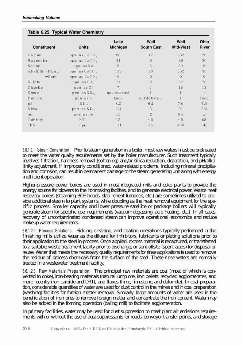
7/17/2019 Steel Plants Fuels and Water Consumption
http://slidepdf.com/reader/full/steel-plants-fuels-and-water-consumption 60/102
6.6.1.2.1 Steam Generat ion Prior to steam generation in a boiler, most raw waters must be pretreatedto meet the water quality requirements set by the boiler manufacturer. Such treatment typicallyinvolves filtration, hardness removal (softening) and/or silica reduction, deaeration, and pH/alka-linity adjustment. If improperly conditioned, water-related problems, including mineral precipita-tion and corrosion, can result in permanent damage to the steam generating unit along with energyinefficient operation.
Higher-pressure power boilers are used in most integrated mills and coke plants to provide theenergy source for blowers to the ironmaking facilities, and to generate electrical power. Waste heatrecovery boilers (steaming BOF hoods, slab reheat furnaces, etc.) are sometimes utilized to pro-vide additional steam to plant systems, while doubling as the heat removal equipment for the spe-cific process. Smaller capacity and lower pressure satellite or package boilers will typicallygenerate steam for specific user requirements (vacuum degassing, acid heating, etc.). In all cases,recovery of uncontaminated condensed steam can improve operational economics and reducemakeup water requirements.
6.6.1.2.2 Process Solutions Pickling, cleaning, and coating operations typically performed in thefinishing mills utilize water as the diluent for inhibitors, lubricants or plating solutions prior to
their application to the steel in-process. Once applied, excess material is recaptured, or transferredto a suitable waste treatment facility prior to discharge, or sent offsite (spent acids) for disposal orreuse. Water that meets the necessary quality requirements for rinse applications is used to removethe residue of process chemicals from the surface of the steel. These rinse waters are normallytreated in a wastewater treatment facility.
6.6.1.2.3 Raw Materials Preparat ion The principal raw materials are coal (most of which is con-verted to coke), iron-bearing materials (natural lump ore, iron pellets, recycled agglomerates, andmore recently iron carbide and DRI), and fluxes (lime, limestone, and dolomite). In coal prepara-tion, considerable quantities of water are used for dust control in the mines and in coal preparation(washing) facilities for foreign matter removal. Similarly, large amounts of water are used in thebeneficiation of iron ores to remove foreign matter and concentrate the iron content. Water may
also be added in the forming operation (balling mill) to facilitate agglomeration.
In primary facilities, water may be used for dust suppression to meet plant air emissions require-ments with or without the use of dust suppressants for roads, conveyor transfer points, and storage
Ironmaking Volume
338 C opyright © 1999, The A IS E S teel Foundation, Pittsburgh, PA . A ll rights reserved.
Table 6.25 Typical Water Chemistry
Lake Well Well Ohio
Constituent Units Michigan South East Mid-West River
C alcium ppm as C aC O 3 80 17 282 70
M agnesium ppm as C aC O 3 41 6 86 30Sodium ppm as N a 9 5 39 9
A lkalinity –Bicarb ppm as C aC O 3 113 20 352 30
–C arb ppm as C aC O 3 0 0 0 0
Sulfate ppm as SO 4 17 2 52 76
C hloride ppm as C l 7 6 18 13
N itrate ppm as N O 3 not detected 1 1 1
Fluoride ppm as F trace not detected 1 trace
pH S.U . 8.2 6.4 7.6 7.3
Silica ppm as SiO 2 2.3 5 31 5.6
Iron ppm as Fe 0.1 .2 6.5 .3
Turbidity N TU 12 < 5 < 5 88TD S ppm 171 46 488 143
7/17/2019 Steel Plants Fuels and Water Consumption
http://slidepdf.com/reader/full/steel-plants-fuels-and-water-consumption 61/102
piles. In pulverized coal injection (PCI) for blast furnaces, moisture content is monitored and addi-tions may be made.
6.6.1.2.4 Potable Systems These systems provide the drinking and convenience water for human con-sumption. Primary concerns are for heavy metal content, water clarity, selected organic com-pounds, and the absence of biological activity. Except in remote plant sites, both potable supplies
and sanitary wastewater treatment are normally provided by municipal systems.
6.6.2 Water -Related Pr oblemsSome of the properties of water that make it useful for so many purposes can also contribute to thecreation of problems in its use. Water’s ability to dissolve, entrain, and suspend solids, liquids, orgases can affect the purity of the water being used and can subsequently affect piping, equipment,and the process. Contamination of the water can subsequently limit its use in many instances untilsuitable treatment can remove or modify the concentration of offending constituents.
Water-related problems can be generally classif ied in four different categories: corrosion, scaling,fouling, or biological activity.
6.6.2.1 Corrosion
Corrosion is an electrochemical process by which a base metal reverts to its oxide form. Corrosioncan be of a general nature, localized (pitting), or galvanic. For corrosion to occur, a corrosion cell,consisting of an anode, a cathode, and an electrolyte, must be present. Water is an excellent elec-trolyte. The most common evidence of corrosion is the visible loss of base metal in piping and wet-ted equipment, and the presence of the resultant oxide (rust). Impurities in the water can affect therate of metal loss.
Specific mechanisms can be responsible for the metal loss or failure. Galvanic corrosion occurswhen two dissimilar metals are in contact in an aqueous environment, resulting in loss of the anodic
metal; this can occur on a macro or micro level. Beneath deposition, concentration cell corrosioncan be established via various mechanisms, resulting in potentially aggressive localized attack (pit-ting). Stress corrosion cracking can occur when metal is subjected to tensile stress in a corrosiveenvironment. Fatigue corrosion occurs in an acidic environment when the metal is subjected tocyclic application of stress. Impingement or erosion/corrosion attack occurs when entrained solidsor gases repeatedly wear the affected metal due to physical/chemical mechanisms.
6.6.2.2 Scaling
Scaling is a chemical process by which certain minerals become insoluble, precipitate from thesolution, and deposit onto equipment surfaces. Scaling is most commonly associated with salts of calcium and magnesium. Common to both of these elements is their inverse solubility in water rel-ative to temperature; as the localized water temperature rises, the solubility of these species drops. The solubility of these minerals is greatly dependent on their relative concentrations, water tem-perature, pH, alkalinity, types of anions present, and other water parameters. Should localized boil-ing to dryness occur, elements including normally soluble ions such as sodium may also precipitateout. The most common evidence of scale formation is the growth of mineral deposition in pipingand heat transfer surfaces.
6.6.2.3 Fouling
Fouling is the deposition of suspended material in the water, originating from internal or externalsources. The most common evidence of fouling is the accumulation of foulants in low-flow areas
and in flow channel restrictions. Foulants can include items such as insects, mollusks, silt, rust, oilsand greases, scale formed in other areas, and other miscellaneous debris. The presence of soft films(i.e., oils/greases/biological masses) can facilitate the growth of deposition by capturing normallysuspended material and forming a fouling matrix of material.
Steel Plant Fuels and Water Requirements
C opyright © 1999, The A IS E S teel Foundation, Pittsburgh, PA . A ll rights reserved. 339
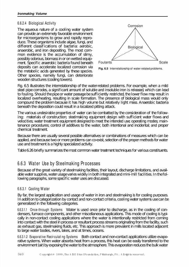
7/17/2019 Steel Plants Fuels and Water Consumption
http://slidepdf.com/reader/full/steel-plants-fuels-and-water-consumption 62/102
6.6.2.4 Biological Activity
The aqueous nature of a cooling water systemcan provide an extremely favorable environmentfor microorganisms to grow and rapidly repro-duce. These organisms include algae, fungi, and
different classif ications of bacteria: aerobic,anaerobic, and iron depositing. The most com-mon evidence is the accumulation of slimy,possibly odorous, biomass in or on wetted equip-ment. Specific anaerobic bacteria found beneathdeposits can accelerate localized corrosion viathe metabolic acids generated by these species.Other species, namely fungi, can deterioratewooden structures (cooling towers).
Fig. 6.5 illustrates the interrelationship of the water-related problems. For example, when a mildsteel pipe corrodes, a significant amount of soluble and insoluble iron is released, which can lead
to fouling. Should the pipe or water passage be sufficiently restricted, the lower flow may result inlocalized overheating, resulting in scale formation. The presence of biological mass would onlycompound the problem because it has high volume but relatively light mass. Anaerobic bacteriabeneath the deposition could result in a localized pitting attack.
The various undesirable properties of water can be combatted by the consideration of the follow-ing: materials of construction; steelmaking equipment design with sufficient water flows andvelocities; water treatment equipment designed to meet the intended use; operating modes; main-tenance procedures; control of additives to the water, both intentional and incidental; and properchemical treatment.
Because there are usually several possible alternatives or combinations of measures which can be
applied, and because two or more problems can co-exist, selection of the proper methods for wateruse and treatment is a highly specialized activity.
Table 6.26 briefly summarizes the most common water treatment techniques for various constituents.
6.6.3 Wat er Use by Steelmaking Pr ocessesBecause of the great variety of steelmaking facilities, their layout, discharge limitations, and avail-able water supplies, water usage varies widely in both integrated and mini-mill facilities. In the fol-lowing paragraphs, some specific water uses are discussed.
6.6.3.1 Cooling W ater
By far, the largest application and usage of water in iron and steelmaking is for cooling purposes.In addition to categorization by contact and non-contact criteria, cooling water systems use can begeneralized in the following categories.
6.6.3.1.1 Once-through Systems Water is used once prior to discharge, as in the cooling of con-densers, furnace components, and other miscellaneous applications. This mode of cooling is typi-cally in non-contact cooling applications where the water is intentionally restricted from cominginto contact with the steel in process or resultant process streams originating from the facility, suchas exhaust gas, steelmaking fluids, etc. This approach is more prevalent in mills located adjacentto large water bodies, rivers, lakes, and at times, oceans.
6.6.3.1.2 Evaporat ive Recir culati ng Systems Both contact and non-contact applications utilize evapo-rative systems. When water absorbs heat from a process, this heat can be easily transferred to theenvironment (air) by exposing the water to the atmosphere. This evaporation reduces the bulk water
Ironmaking Volume
340 C opyright © 1999, The A IS E S teel Foundation, Pittsburgh, PA . A ll rights reserved.
Corrosion
ScaleFoulants
Biological
Fig. 6.5 Interrelationship of water-related problems.
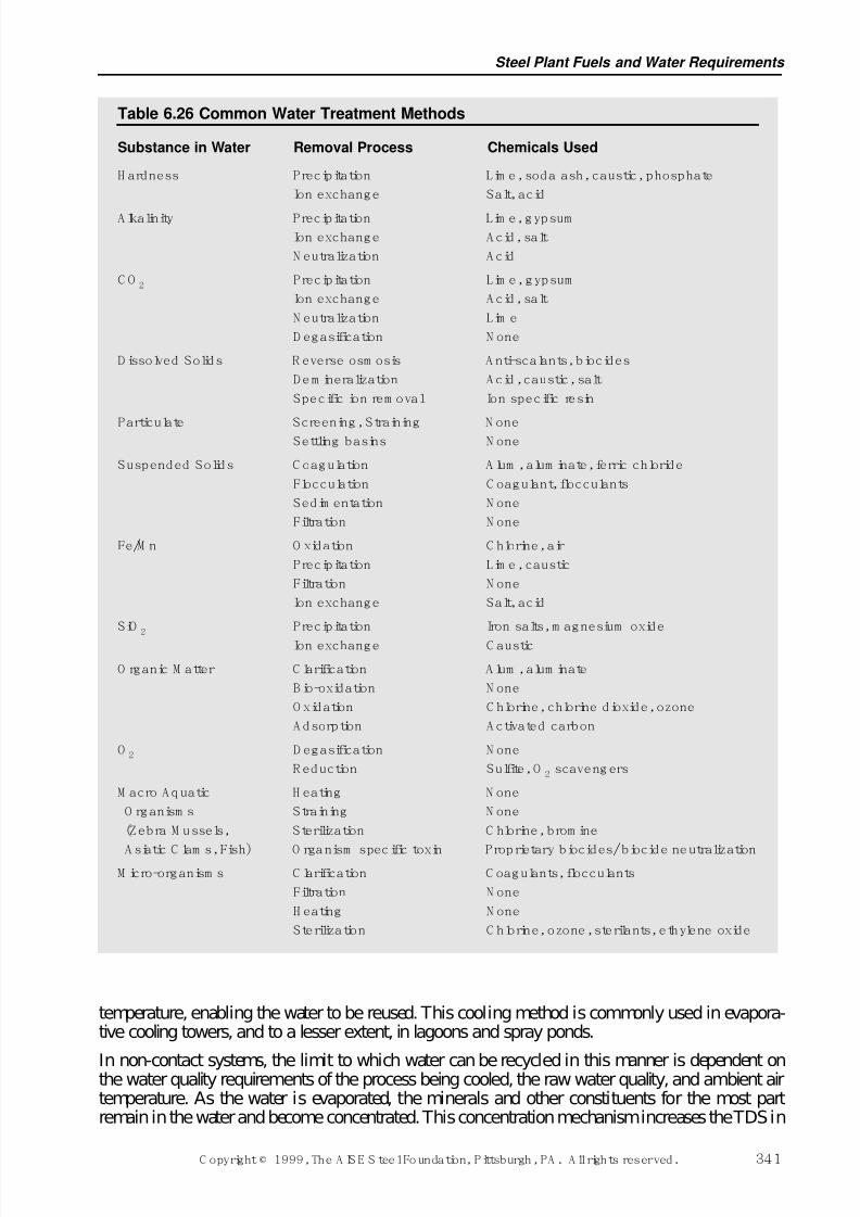
7/17/2019 Steel Plants Fuels and Water Consumption
http://slidepdf.com/reader/full/steel-plants-fuels-and-water-consumption 63/102
temperature, enabling the water to be reused. This cooling method is commonly used in evapora-tive cooling towers, and to a lesser extent, in lagoons and spray ponds.
In non-contact systems, the limit to which water can be recycled in this manner is dependent onthe water quality requirements of the process being cooled, the raw water quality, and ambient airtemperature. As the water is evaporated, the minerals and other constituents for the most partremain in the water and become concentrated. This concentration mechanism increases the TDS in
Steel Plant Fuels and Water Requirements
C opyright © 1999, The A IS E S teel Foundation, Pittsburgh, PA . A ll rights reserved. 341
Table 6.26 Common Water Treatment Methods
Substance in Water Removal Process Chemicals Used
H ardness Precipitation Lim e, soda ash, caustic, phosphate
Ion exchange Salt, acid
A lkalinity Precipitation Lim e, gypsum
Ion exchange A cid, salt
N eutralization A cid
C O 2 Precipitation Lim e, gypsum
Ion exchange A cid, salt
N eutralization Lim e
D egasification N one
D issolved Solids R everse osm osis A nti-scalants, biocides
Dem ineralization Acid, caustic, salt
Specific ion rem oval Ion specific resin
Particulate Screening, Straining N oneSettling basins N one
Suspended Solids C oagulation A lum , alum inate, ferric chloride
Flocculation C oagulant, flocculants
Sedim entation N one
Filtration N one
Fe/M n O xidation C hlorine, air
Precipitation Lim e, caustic
Filtration N one
Ion exchange Salt, acid
SiO 2 Precipitation Iron salts, m agnesium oxide
Ion exchange C austic
O rganic M atter C larification A lum , alum inate
B io-oxidation N one
O xidation C hlorine, chlorine dioxide, ozone
A dsorption A ctivated carbon
O 2 D egasification N one
R eduction Sulfite, O 2 scavengers
M acro A quatic H eating N one
O rganism s Straining N one
(Zebra M ussels, Sterilization C hlorine, brom ine
A siatic C lam s, Fish) O rganism specific toxin Proprietary biocides/ biocide neutralizationM icro-organism s C larification C oagulants, flocculants
Filtration N one
H eating N one
Sterilization C hlorine, ozone, sterilants, ethylene oxide
7/17/2019 Steel Plants Fuels and Water Consumption
http://slidepdf.com/reader/full/steel-plants-fuels-and-water-consumption 64/102
the system and, if not compensated, may lead to water-related problems, as discussed in Section6.6.2. Normally, the TDS concentration in the system is controlled by bleeding off some of thewater from the system (blowdown).
The same is true for contact cooling water systems, and consideration must be given to the con-stituents originating from the process. These systems often require some treatment for the removal
of solids, oil, etc., prior to cooling and recycle.In both contact and non-contact cooling systems, the amount of recycle that is obtainable is highlydependent on the water quality requirements and constraints of the systems being cooled. Becauseof this, some discharge blowdown is required from these systems to maintain the desired waterquality. The balance for an evaporative water system is dictated by the following interrelationshipbetween makeup, evaporation, and blowdown. (Note that blowdown in this equation includesuncontrolled losses such as tower drift, windage losses, exhaust entrainment, spillage, and leakage.)
Makeup (MU) Evaporation (EV) Blowdown (BD) (6.6.1)
Cycles of concentration and concentration ratio are terms used to indicate the degree of concen-tration of the recirculating water as compared to that of the makeup water. The degree of concen-
tration is dictated by the relationship of makeup to blowdown, given that evaporation (heat load) isconstant over time. The evaporating water is pure water vapor, leaving behind soluble water impu-rities that can be measured. Analytically, measurement of these dissolved minerals in the makeupand blowdown can also indicate this concentration phenomenon as shown below:
(6.6.2)
An accepted rule of thumb to estimate evaporation in a recirculating system is for every 6°C (10°F)temperature drop across the evaporative process, 1% of the recirculating water is lost to evapora-tion. This 1% rule of thumb may vary. In areas of high humidity (Gulf Coast), evaporative loss may
be as low as 0.75%, while in arid areas, as high as 1.2%. A second method to determine makeup(MU) is as follows:
(6.6.3)
In direct contact systems, when water is applied to hot steel in process, analytical measurement of dissolved salts may be skewed. Some of the mineral content may precipitate out on the hot surfaceof steel in process as the water evaporates. Conversely, soluble elements from the process may alsodissolve in the water, increasing their level, as in the gas cleaning applications of water.
6.6.3.1.3 Non-evapor ative ( Closed) Recirculation Systems Incorporating the use of a heat exchanger
mechanism, the recirculated water system heat is transferred to a second water system or to the airthrough conductive cooling. This transfer is accomplished through water/water heat exchangers of plate and frame or shell and tube design, or through air coolers of wet surface or dry design. Thesame cooling water is used in a continuous cycle with little or no water loss. Usually associatedwith higher water quality applications, these systems are typically not exposed directly to the envi-ronment and do not have a concentration mechanism. In everyday life, the automobile radiatorcooling system is a common example of a closed loop cooling system.
6.6.3.1.4 Application of Cooling Water Systems Most once-through systems are limited to non-contactor indirect cooling applications. Previously, contact or direct cooling applications were of the once-through design, but these generally have been converted to recirculating systems, incorporating
primarily evaporative cooling towers to meet discharge requirements. Most closed non-evaporativesystems are used to cool process equipment requiring higher quality water in terms of hardness,suspended solids, and dissolved solids. Often these requirements necessitate pretreatment of thewater to meet the desired characteristics.
MU EVCR
CR=
−
1
Concentration Ratio (CR) =MU (gpm)
BD (gpm)
Conc (BD)
Conc (MU)=
Ironmaking Volume
342 C opyright © 1999, The A IS E S teel Foundation, Pittsburgh, PA . A ll rights reserved.
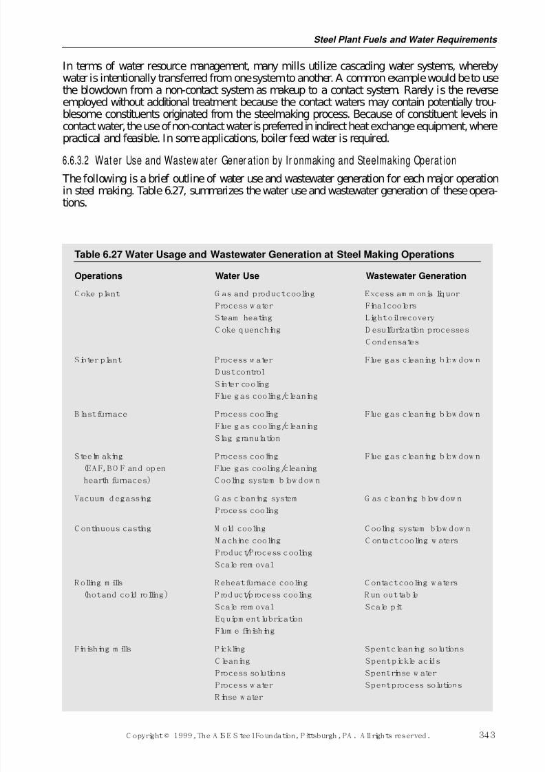
7/17/2019 Steel Plants Fuels and Water Consumption
http://slidepdf.com/reader/full/steel-plants-fuels-and-water-consumption 65/102
In terms of water resource management, many mills utilize cascading water systems, wherebywater is intentionally transferred from one system to another. A common example would be to usethe blowdown from a non-contact system as makeup to a contact system. Rarely is the reverseemployed without additional treatment because the contact waters may contain potentially trou-blesome constituents originated from the steelmaking process. Because of constituent levels incontact water, the use of non-contact water is preferred in indirect heat exchange equipment, where
practical and feasible. In some applications, boiler feed water is required.
6.6.3.2 Wat er Use and Wastew ater Gener ation by Ir onmaking and Steelmaking Operat ion
The following is a brief outline of water use and wastewater generation for each major operationin steel making. Table 6.27, summarizes the water use and wastewater generation of these opera-tions.
Steel Plant Fuels and Water Requirements
C opyright © 1999, The A IS E S teel Foundation, Pittsburgh, PA . A ll rights reserved. 343
Table 6.27 Water Usage and Wastewater Generation at Steel Making Operations
Operations Water Use Wastewater Generation
C oke plant G as and product cooling Excess am m onia liquor
Process w ater Final coolers
Steam heating Light oil recovery
C oke quenching D esulfurization processes
C ondensates
Sinter plant Process w ater Flue gas cleaning blow dow n
D ust control
Sinter cooling
Flue g as cooling/cleaning
B last furnace Process cooling Flue gas cleaning blow dow n
Flue g as cooling/cleaning
Slag granulation
Steelm aking Process cooling Flue gas cleaning blow dow n
(EA F, B O F and op en Flue gas cooling/cleaning
hearth furnaces) C ooling system b low dow n
Vacuum d egassing G as cleaning system G as cleaning blow dow n
Process cooling
C ontinuous casting M old cooling C ooling system blow dow n
M achine cooling C ontact cooling w atersProduct/Process cooling
Scale rem oval
R olling m ills R eheat furnace cooling C ontact cooling w aters
(hot and cold rolling) P rod uct/p rocess cooling R un out tab le
Scale rem oval Scale pit
Equipm ent lubrication
Flum e finishing
Finishing m ills Pickling Spent cleaning solutions
C leaning Spent pickle acids
Process solutions Spent rinse w aterProcess w ater Spent process solutions
R inse w ater
7/17/2019 Steel Plants Fuels and Water Consumption
http://slidepdf.com/reader/full/steel-plants-fuels-and-water-consumption 66/102
6.6.3.2.1 Coke and Coal Chemical Plants The largest volume of water used in these plants is for non-contact cooling in a variety of cooling and condensing operations. Moisture from the coal beingcoked and from process steam condensation makes the byproduct operation a net generator of process water. Process wastewater sources include: excess ammonia liquor from the primarycooler tar decanter, and barometric condenser wastewater from the crystallizer, the final coolers,light oil recovery operations, desulfurization processes, and air pollution control operations. Mostof the wastewater generated at the coke plant results from moisture in the coal and steam conden-sate. Additional sources can include condensates from drip legs and gas lines.
The largest consumption of water in coke plants is for the quenching of coke. The amount of waterrequired for coke quenching can vary and has been reported to be from 400 to 3000 litres/tonne(120 to 900 gallons per ton). A sufficient quantity of water is needed to cool the coke, yet leaveenough heat in the coke to evaporate any entrained water. Some facilities utilize untreated processwastewater for coke quenching, while others use treated process waters or service waters. In someareas, the level of TDS in the quench water must be controlled due to potential air pollution con-cerns. This requirement has impacted the use of untreated process wastewater in coke quenching.
6.6.3.2.2 Sinter Plants The principal uses of water in a sintering plant are for controlling the mois-
ture content of the pre-sinter mix, for dust control, and for sinter product cooling. Some indirectcooling of equipment is involved. For emissions control in sinter plants, either electrostatic pre-cipitator or wet venturi-type scrubber technology is typically employed for dust control. In precip-itator applications, some water may be added to control exhaust temperature and to condition theparticulate prior to capture.
In scrubber systems, water is sprayed into the gas stream to capture the emissions from the sinteroperation to meet stack emissions requirements. The associated water system will typically includeclarifying thickeners, a cooling tower, and pH Adjustment.
6.6.3.2.3 Blast Fur nace The blast furnace is one of the largest water users in an integrated steel milloperation. The primary water use is for non-contact cooling of various parts of the furnace and aux-
iliaries, including the tuyeres, hearth staves, bosh, cooling plates and staves, cinder notch, and stovevalves. The historical approach has been to use once-through cooling water, but recent construc-tion and modernizations have incorporated evaporative cooling systems along with closed-loopwater systems for hot blast valves, tuyeres, and staves. Additional water is used for furnace mois-ture injection (steam), dust control, and slag granulation.
Contact water use is primarily associated with blast-furnace gas cleaning operations necessary torecover the fuel value of the offgas for use in stove and boiler operations. In venturi-type scrubbersand spray-cooled gas coolers, water contacts, cleans, and cools the gas for reuse. This water sys-tem usually consists of thickeners, dewatering devices, and evaporative cooling towers. Chemicaltreatment may consist of settling aids, pH adjustment, and inhibitors, depending on the nature of the particulate and gas exiting the furnace. As the amount of recycle is increased in these systems,
the control of total dissolved solids (TDS) and the increased concentration of specifically moni-tored elements or compounds become concerns.
Treatment for the reduction of TDS would be dependent upon the parameters of concern and couldinvolve more sophisticated treatment systems. Typically, the blast-furnace process waters containammonia, phenols, cyanide, lead, and zinc. Additional treatment for these parameters may berequired prior to discharge of any blowdown from the recycle system. In many facilities, a signif-icant portion of the recirculated water can be consumed rather than discharged by utilizing it forslag quenching.
6.6.3.2.4 Alternative Iron Technologies With the increased tonnage produced via the electric arc fur-nace, the direct reduced iron, iron carbide, and Corex processes play a meaningful role in the steel
industry. Likewise, they also have water requirements. Because these technologies produce asource of iron units in varying forms, their process requirements can be similar to those of a blastfurnace. However, their gas handling system is much more complex due to the nature of the tech-nologies. In general, each of these processes has non-contact cooling requirements for compres-
Ironmaking Volume
344 C opyright © 1999, The A IS E S teel Foundation, Pittsburgh, PA . A ll rights reserved.
7/17/2019 Steel Plants Fuels and Water Consumption
http://slidepdf.com/reader/full/steel-plants-fuels-and-water-consumption 67/102
sors, coolers, and various furnace shell components. Closed non-evaporative systems are prevalentfor this application.
The gas exiting the shaft furnace in these processes is utilized extensively in the process andrequires cleaning prior to reuse. Wet scrubbers are installed in the dirty system to perform thisfunction. The water system usually consists of thickeners, dewatering devices, and evaporative
cooling towers. Chemical treatment may consist of settling aids, pH adjustment, and inhibitorsbecause of the nature of the particulate and gas composition in the dirty gas exiting the furnace.
A clean gas contact system, using water mainly as a process gas coolant, is also used to maintainprocess gas temperature requirements. This system is cooled via an open evaporative cooling tower.
Water treatment to meet the process requirements for each of the systems can be extensive. Thecontact systems in particular may require extensive water treatment and quality adjustment inprocess to maintain plant operations.
6.6.3.2.5 Elect r ic Arc Fur naces The EAF can also be an extensive user of water, particularly for non-contact cooling functions. In the melt shop, emissions in the exhaust gas stream are typically han-dled using baghouse technology, requiring no contact water. Non-contact water applications
include water-cooled ductwork, roof, sidewalls, doors, injection lances, panels, electrode clamps,cables, and arms. These systems usually incorporate evaporative cooling towers, while a numberof applications incorporate closed cooling loops. Some applications utilize closed-loop high-puritysystems for electrical apparatus cooling requiring low conductivity (dissolved solids) water. Aswith other primary operations, the control of TDS in evaporative cooling systems for electric arcfurnaces is a significant concern.
6.6.3.2.6 Basic Oxygen Furnace The BOF and its derivatives are extensive users of water. Non-contact cooling is used for the vessel hood, ductwork, trunnion, and oxygen lance. Both closed-loop and evaporative systems are prevalent for handling the cooling requirements for these com-ponents, based on manufacturer recommendations. The trend for hood cooling in recent years has
been toward the closed-loop cooling approach to extend hood life. Some BOF hoods are steamgenerating, with water requirements similar to those of high pressure boiler applications.
Gas handling for the various basic oxygen processes can be categorized as either full combustion(open) or suppressed combustion (closed) hood systems. In full combustion systems, excess air isallowed to enter the exhaust stream in the hood. This enables the oxygen blow to accomplish acomplete reaction, converting CO to CO2. In suppressed combustion systems, the hood is skirtedto prevent excess air from entering the exhaust. Typically, the amount of particulate emissions gen-erated by either approach equals 1–3% of the steel tonnage produced. The suppressed combustionapproach has gained favor because the particulate generated is generally larger (except in the OBMor Q-BOP process), the temperatures generated in the hood are generally lower, and the volume of gas is lower, thereby reducing the size of the equipment required to convey and clean the gas.
In either full or suppressed combustion gas cleaning systems, water is used for initial cooling of the gas in the ductwork and/or in a quencher to reduce gas temperature and volume. Full combus-tion gas cleaning systems can incorporate either electrostatic precipitator (semi-wet) or venturiscrubber (wet) technology. After initial conditioning in a precipitator-based system, little or nowater is used because the captured dust is handled on a dry basis. Precipitators are generally notused on suppressed combustion systems because the potential for explosion exists due to the pres-ence of CO gas; the few facilities with suppressed combustion and precipitators have incorporateddesign considerations accommodating the potential explosion hazards.
The scrubber-based system typically incorporates separate quencher and venturi-type scrubbers forgas cooling and cleaning purposes. The auxiliary water systems typically consist of a clarifying
thickener and dewatering devices for the solids captured. Upon exiting the thickener, the cleanedwater is returned to the venturi, typically without cooling. After the venturi scrubber, the venturieffluent is typically reused as supply to the quencher. In some facilities, a separate gas cooler witha dedicated cooling tower is in line, after the scrubber but prior to the exhaust fan and stack.
Steel Plant Fuels and Water Requirements
C opyright © 1999, The A IS E S teel Foundation, Pittsburgh, PA . A ll rights reserved. 345
7/17/2019 Steel Plants Fuels and Water Consumption
http://slidepdf.com/reader/full/steel-plants-fuels-and-water-consumption 68/102
Because of the lime carryover in the exhaust gas, the high gas temperature, and the fine particu-late nature of the dust evolved, water-related problems, including mineral precipitation and foul-ing, can interfere with scrubber operations. Problems include plugging of the venturi nozzles andfouling in the venturi/quencher throats. Various water quality treatment approaches are incorpo-rated, including pH/alkalinity control, solids management, and various inhibitor programs.
6.6.3.2.7 Ladle M etallurgy Furnace Water usage for the LMF is similar to the EAF, although its func-tion and design are different. Non-contact water is used to cool the roof, clamps, arms, cables, andassociated equipment. Cooling is typically via an open recirculating system and is combined withthe EAF system if plant layout allows.
6.6.3.2.8 Vacuum Degasser Water usage is primarily associated with the vacuum generating/gascleaning system. The vacuum is generated by injecting steam through multi-point eductors leadingto a barometric condenser. As the steel exhaust emissions are drawn in contact with the steam, theparticulate is wetted and collects in the condenser water. The water system may consist of an evap-orative cooling tower, solids settling, and solids removal equipment.
Depending on the facility design, non-contact water may be used to meet equipment coolingrequirements. Typically, these cooling requirements will be met by evaporative towers associatedwith the EAF/LMF facilities.
6.6.3.2.9 Continuous Casting Water use and quality are critical to the success of continuous casting.Water use in the caster is categorized by function in the casting process: primary (mold); sec-ondary (spray); and auxiliary (equipment). When continuous casting was initially adopted by thesteel industry, little attention was given to water quality and one evaporatively cooled system wasinstalled to provide the cooling requirements.
As with the casting process itself, water management practices evolved as demands for equipmentreliability and quality grew. A signif icant improvement was made when the mold circuit was iso-lated as a non-contact (closed) system, virtually eliminating process contamination and mineralscaling as the cause for mold related failures. Further improvements were made when contact cool-
ing and non-contact requirements were separated into separate water systems.
The primary cooling process is the non-contact cooling of the molten steel shell in the mold to itssemi-finished form by passing high quality water through a highly conductive copper mold.Closed-loop non-evaporative cooling is primarily employed when high surface and strand qualityare required. Because of the high heat flux encountered in the mold, pretreatment is normally spec-ified for removal of scale-forming constituents. Open recirculating evaporative systems are some-times used where makeup water quality and caster quality requirements allow.
Secondary or spray cooling occurs as the strand exits the mold, with contact water sprays coveringthe surface of the strand. Spray cooling allows for the extraction of heat as it migrates from themolten core to the surface until solidification is complete. This contact water system will typically
incorporate settling basins (scale pits), oil skimmers, straining devices, and deep bed filtrationequipment when low suspended solids levels are to be maintained. Water treatment should includeconsideration of contamination from grease, hydraulic fluids, and mold lubricants that will be col-lected and concentrated in this system. As with other contact systems, this system will typicallyutilize evaporative tower systems for cooling.
Auxiliary cooling is non-contact or internal cooling of the casting equipment. Applications typi-cally include heat exchangers, internal roll cooling, frames, bearings, compressors, exposed instru-mentation, and other miscellaneous components. Evaporative cooling systems are prevalent forthese applications. Electromagnetic stirring devices and high temperature exposed componentssuch as center bearings may require the installation of closed-loop cooling systems, which mayrequire high-quality water.
Cascading water systems are not unusual in caster systems as water quality requirements are typi-cally less stringent for contact systems than for non-contact systems. Cascading often occurs unin-tentionally because of equipment leaks during normal operations.
Ironmaking Volume
346 C opyright © 1999, The A IS E S teel Foundation, Pittsburgh, PA . A ll rights reserved.
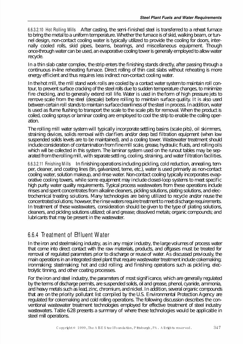
7/17/2019 Steel Plants Fuels and Water Consumption
http://slidepdf.com/reader/full/steel-plants-fuels-and-water-consumption 69/102
6.6.3.2.10 Hot Rolling Mills After casting, the semi-finished steel is transferred to a reheat furnaceto bring the metal to a uniform temperature. Whether the furnace is of skid, walking beam, or tun-nel design, non-contact cooling water is typically utilized to provide the cooling for doors, inter-nally cooled rolls, skid pipes, beams, bearings, and miscellaneous equipment. Thoughonce-through water can be used, an evaporative cooling tower is generally employed to allow waterrecycle.
In a thin slab caster complex, the strip enters the finishing stands directly, after passing through acontinuous in-line reheating furnace. Direct rolling of thin cast slabs without reheating is moreenergy efficient and thus requires less indirect non-contact cooling water.
In the hot mill, the mill stand work rolls are cooled by a contact water system to maintain roll con-tour, to prevent surface cracking of the steel rolls due to sudden temperature changes, to minimizefire checking, and to generally extend roll life. Water is used in the form of high pressure jets toremove scale from the steel (descale) before rolling to maintain surface quality. It is also usedbetween certain roll stands to maintain surface cleanliness of the steel in process. In addition, wateris used as flume flushing to transport the scale to the scale pits for removal. When the product iscoiled, cooling sprays or laminar cooling are employed to cool the strip to enable the coiling oper-
ation. The rolling mill water system will typically incorporate settling basins (scale pits), oil skimmers,straining devices, solids removal with clarifiers and/or deep bed filtration equipment (when lowsuspended solids levels are to be maintained), and a cooling tower. Wastewater treatment shouldinclude consideration of contamination from fine mill scale, grease, hydraulic fluids, and rolling oilswhich will be collected in this system. The laminar system used on the runout tables may be sep-arated from the rolling mill, with separate settling, cooling, straining, and water filtration facilities.
6.6.3.2.11 Finishing M ills In finishing operations including pickling, cold reduction, annealing, tem-per, cleaner, and coating lines (tin, galvanized, terne, etc.), water is used primarily as non-contactcooling water, solution makeup, and rinse water. Non-contact cooling typically incorporates evap-
orative cooling towers, while some equipment may include closed-loop systems to meet specifichigh purity water quality requirements. Typical process wastewaters from these operations includerinses and spent concentrates from alkaline cleaners, pickling solutions, plating solutions, and elec-trochemical treating solutions. Many technologies are being utilized to recycle and/or reuse theconcentrated solutions; however, the rinse waters require treatment to meet discharge requirements.In treatment of these wastewaters, consideration should be given to the type of plating solutions,cleaners, and pickling solutions utilized; oil and grease; dissolved metals; organic compounds; andlubricants that may be present in the wastewater.
6.6.4 Tr eatment of Eff luent W aterIn the iron and steelmaking industry, as in any major industry, the large volumes of process waterthat come into direct contact with the raw materials, products, and offgases must be treated forremoval of regulated parameters prior to discharge or reuse of water. As discussed previously, themain operations in an integrated steel plant that require wastewater treatment include cokemaking;ironmaking; steelmaking; hot and cold rolling; and finishing operations such as pickling, elec-trolytic tinning, and other coating processes.
For the iron and steel industry, the parameters of most significance, which are generally regulatedby the terms of discharge permits, are suspended solids, oil and grease, phenol, cyanide, ammonia,and heavy metals such as lead, zinc, chromium, and nickel. In addition, several organic compoundsthat are on the priority pollutant list compiled by the U.S. Environmental Protection Agency are
regulated for cokemaking and cold rolling operations. The following discussion describes the con-ventional wastewater treatment technologies employed for effective treatment of steel industrywastewaters. Table 6.28 presents a summary of where these technologies would be applicable insteel mill operations.
Steel Plant Fuels and Water Requirements
C opyright © 1999, The A IS E S teel Foundation, Pittsburgh, PA . A ll rights reserved. 347
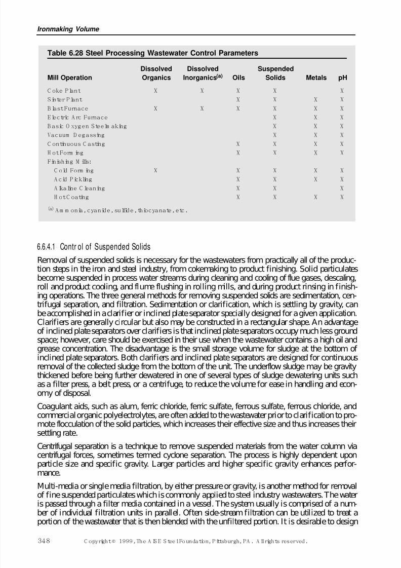
7/17/2019 Steel Plants Fuels and Water Consumption
http://slidepdf.com/reader/full/steel-plants-fuels-and-water-consumption 70/102
6.6.4.1 Contr ol of Suspended Solids
Removal of suspended solids is necessary for the wastewaters from practically all of the produc-tion steps in the iron and steel industry, from cokemaking to product finishing. Solid particulatesbecome suspended in process water streams during cleaning and cooling of flue gases, descaling,roll and product cooling, and flume flushing in rolling mills, and during product rinsing in finish-
ing operations. The three general methods for removing suspended solids are sedimentation, cen-trifugal separation, and filtration. Sedimentation or clarification, which is settling by gravity, canbe accomplished in a clarifier or inclined plate separator specially designed for a given application.Clarifiers are generally circular but also may be constructed in a rectangular shape. An advantageof inclined plate separators over clarifiers is that inclined plate separators occupy much less groundspace; however, care should be exercised in their use when the wastewater contains a high oil andgrease concentration. The disadvantage is the small storage volume for sludge at the bottom of inclined plate separators. Both clarifiers and inclined plate separators are designed for continuousremoval of the collected sludge from the bottom of the unit. The underflow sludge may be gravitythickened before being further dewatered in one of several types of sludge dewatering units suchas a filter press, a belt press, or a centrifuge, to reduce the volume for ease in handling and econ-omy of disposal.
Coagulant aids, such as alum, ferric chloride, ferric sulfate, ferrous sulfate, ferrous chloride, andcommercial organic polyelectrolytes, are often added to the wastewater prior to clarification to pro-mote flocculation of the solid particles, which increases their effective size and thus increases theirsettling rate.
Centrifugal separation is a technique to remove suspended materials from the water column viacentrifugal forces, sometimes termed cyclone separation. The process is highly dependent uponparticle size and specific gravity. Larger particles and higher specific gravity enhances perfor-mance.
Multi-media or single media filtration, by either pressure or gravity, is another method for removal
of fine suspended particulates which is commonly applied to steel industry wastewaters. The wateris passed through a filter media contained in a vessel. The system usually is comprised of a num-ber of individual filtration units in parallel. Often side-stream filtration can be utilized to treat aportion of the wastewater that is then blended with the unfiltered portion. It is desirable to design
Ironmaking Volume
348 C opyright © 1999, The A IS E S teel Foundation, Pittsburgh, PA . A ll rights reserved.
Table 6.28 Steel Processing Wastewater Control Parameters
Dissolved Dissolved Suspended
Mill Operation Organics Inorganics(a) Oils Solids Metals pH
C oke Plant X X X X X
Sinter Plant X X X XB last Furnace X X X X X X
Electric A rc Furnace X X X
B asic O xygen Steelm aking X X X
Vacuum D egassing X X X
C ontinuous C asting X X X X
H ot Form ing X X X X
Finishing M ills:
C old Form ing X X X X X
A cid Pickling X X X X
A lkaline C leaning X X X
H ot C oating X X X X(a) A m m onia, cyanide, sulfide, thiocyanate, etc.
7/17/2019 Steel Plants Fuels and Water Consumption
http://slidepdf.com/reader/full/steel-plants-fuels-and-water-consumption 71/102
a filter system with the highest feasible flow rate through the filter media to minimize the requiredsize and cost.
In a typical multi-media system, the water first passes through a relatively coarse layer of mediasuch as anthracite coal, and then through a layer of fine sand. Most of the particulates are removedby the coarse layer, while the fine layer does the final polishing. Multi-media filters are often used
when oil and grease concentrations are elevated in the wastewaters. High oil and grease concen-trations can result in fouling and/or plugging of the media in both single and multi-media filters.Periodically, the collected particulate must be removed from the filter media by backwashing. Inthis operation, the influent flow of wastewater is shut off and a stream of treated water, and occa-sionally air, is passed through the filter in the opposite direction to flush out the collected solids.By having a number of filter units installed in parallel, one unit can be put through the backwashcycle without interrupting the continuous treatment of the wastewater stream. The backwashstream is usually settled in a backwash holding tank, and the solids are processed through a thick-ener and sludge dewatering equipment. Both single media and multi-media filters can produce ahigh degree of clarity in effluent streams. However, clarifiers should be considered for pretreat-ment of wastewater heavily laden with solids to remove the majority of the particulates prior to fil-
tration. Filters can be used alone without prior clarification for waste streams with less solids. The quantity of suspended solids and other particulates discharged to a receiving stream can usu-ally be greatly reduced by recirculating the water back to the process. However, the degree of recir-culation that is feasible is limited by the amount of suspended solids present in the wastewater andthe buildup in the concentration of dissolved salts in the system, which can eventually lead to depo-sition and plugging in equipment and piping. Therefore, a certain portion of the circulating watervolume must be released as blowdown to control the concentration of dissolved salts to a tolerablelevel.
6.6.4.2 Control of Oil
Oil and grease are commonly found in wastewaters from continuous casting, hot and cold rolling,pickling, electroplating, and coating operations. The oils originate from machinery and productlubricants and coolants; hydraulic systems; and preservative coatings applied during certain phasesof the production operations. Oil and grease can be removed from process wastewaters by severalmethods including skimming, filtration, gravity separation, air flotation, and ultrafiltration. If theoils are insoluble in water, they can be controlled by gravity separation and skimming. Gravity oilseparators are usually rectangular chambers in which the velocity of the water stream is sloweddown sufficiently to allow time for the oil to float to the surface, from where it is removed by oneof several types of skimming devices. Such devices include the rotary drum, rope and belt typeskimmers, and scraper blades, which are also used to scrape the heavier solids that have settled tothe bottom. Insoluble oils also can be removed along with suspended solids in the multi-media fil-
ters previously described. If the oils are emulsified or water soluble, such as those found in wastecold rolling solutions or rinse waters, they can be treated by acid or commercial emulsion break-ers to break the emulsion, followed by gravity sedimentation and skimming, or by air flotationand/or membrane separation techniques.
Skimming may be used on any wastewater containing constituents that float to the surface and iscommonly used to remove free oil, grease, and soaps. Skimming is often used with air flotation orclarification to improve removal of both settling and floating materials. The removal efficiency of a skimmer is a function of the density of the material to be floated and the retention time of thewastewater in the tank. API or other gravity-type separators tend to be more suitable for use wherethe amount of surface oil flowing through the system is fairly high and consistent.
Air flotation is a process that is used to separate floatable materials having a specific gravity closeto that of water, which therefore cannot be effectively separated by gravity alone. In a flotation sys-tem, gas bubbles, usually air, are released in the wastewater and attach to the oil and fine solid par-ticles, causing them to float more rapidly to the surface where they are skimmed off as a froth.
Steel Plant Fuels and Water Requirements
C opyright © 1999, The A IS E S teel Foundation, Pittsburgh, PA . A ll rights reserved. 349
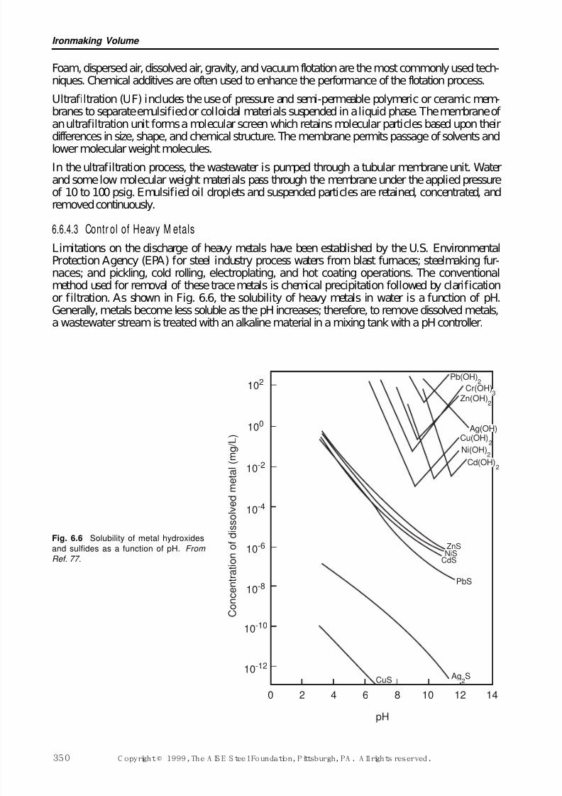
7/17/2019 Steel Plants Fuels and Water Consumption
http://slidepdf.com/reader/full/steel-plants-fuels-and-water-consumption 72/102
Foam, dispersed air, dissolved air, gravity, and vacuum flotation are the most commonly used tech-niques. Chemical additives are often used to enhance the performance of the flotation process.
Ultrafiltration (UF) includes the use of pressure and semi-permeable polymeric or ceramic mem-branes to separate emulsified or colloidal materials suspended in a liquid phase. The membrane of an ultrafiltration unit forms a molecular screen which retains molecular particles based upon their
differences in size, shape, and chemical structure. The membrane permits passage of solvents andlower molecular weight molecules.
In the ultrafiltration process, the wastewater is pumped through a tubular membrane unit. Waterand some low molecular weight materials pass through the membrane under the applied pressureof 10 to 100 psig. Emulsified oil droplets and suspended particles are retained, concentrated, andremoved continuously.
6.6.4.3 Contr ol of Heavy M etals
Limitations on the discharge of heavy metals have been established by the U.S. EnvironmentalProtection Agency (EPA) for steel industry process waters from blast furnaces; steelmaking fur-
naces; and pickling, cold rolling, electroplating, and hot coating operations. The conventionalmethod used for removal of these trace metals is chemical precipitation followed by clarificationor filtration. As shown in Fig. 6.6, the solubility of heavy metals in water is a function of pH.Generally, metals become less soluble as the pH increases; therefore, to remove dissolved metals,a wastewater stream is treated with an alkaline material in a mixing tank with a pH controller.
Ironmaking Volume
350 C opyright © 1999, The A IS E S teel Foundation, Pittsburgh, PA . A ll rights reserved.
ZnSNiS
CdS
PbS
CuS
Pb(OH)2
Zn(OH)2
Cu(OH)2
Ni(OH)2
0 2 4 6 8 10 12 14
C o n c e n t r a t i o n
o f d i s s o l v e d m e t a l ( m g / L )
102
100
10-2
10-4
10-6
10-8
10-10
10-12
Cr(OH)3
Ag(OH)
Cd(OH)2
Ag2S
pH
Fig. 6.6 Solubility of metal hydroxides
and sulfides as a function of pH. From
Ref. 77.
7/17/2019 Steel Plants Fuels and Water Consumption
http://slidepdf.com/reader/full/steel-plants-fuels-and-water-consumption 73/102
Common chemical precipitation processes include hydroxide and sulfide precipitation. In hydrox-ide precipitation, lime, which is the least expensive reagent, is most often used, although causticsoda, magnesium hydroxide, or other alkali may also be employed for this purpose. After the pHis raised to a level where the dissolved metals will precipitate as hydroxides, the water passes toeither a clarifier and/or a filter for removal of the precipitated solids. The addition of a coagulantaid is usually required. The use of a coagulating agent such as ferric chloride at an alkaline pH
results in the formation of an oxy-hydroxide surface, which enhances additional removal of metalsby adsorption. Other coagulants such as alum, ferrous sulfate, and polymeric flocculants also canbe used to enhance particle formation.
If chromium is present in the hexavalent form, it must first be chemically reduced to the trivalentform before it will precipitate. The rate of this reduction reaction is a function of the pH conditionof the system. For example, the pH of the system must be adjusted to between 2.0 and 3.0 if sul-fur dioxide, sodium bisulfite, or spent pickle liquor is used as the reducing agent. Hexavalentchromium can also be reduced to trivalent chromium with sodium hydrosulfite at a relativelyhigher pH (between 8.5 and 9.5). The reduced trivalent chromium ion is then converted to insolu-ble chromium hydroxide and is removed by sedimentation.
As indicated above, dissolved metal ions and certain anions may be chemically precipitated andremoved by physical means such as sedimentation or filtration. In addition to the use of alkalinecompounds, the following other reagents can be used:
1. Metal sulfides—Except for chromium sulfide, the solubility of metal sulfides islower than that of metal hydroxides (see Fig. 6.6). Therefore, the removal of dis-solved metals can be enhanced using the sulfide precipitation process. Both solublesulfides, such as hydrogen sulfide or sodium sulfide, and insoluble sulfides, suchas ferrous sulfide, may be used to precipitate many heavy metal ions as insolublemetal sulfides. Currently, the use of organic sulfide has become popular in thewastewater treatment industry. Typically, the sulfide precipitation process includesclarification and filtration.
2. Carbonates—Carbonate precipitates may be used to remove metals either by directprecipitation using a carbonate reagent such as calcium carbonate or by convertinghydroxides into carbonates using carbon dioxide.
Chemical precipitation as a mechanism for removing metals from wastewater is a complex processconsisting of at least two steps: precipitation of the unwanted metals and removal of the precipi-tate. A small amount of metal will remain dissolved in the wastewater after complete precipitation. The amount of residual dissolved metal depends on the treatment chemicals used, the solubility of the metal, and co-precipitation effects. The effectiveness of this method of removing any specificmetal depends on the fraction of the specific metal in the raw waste (and hence in the precipitate)and the effectiveness of suspended solids removal.
6.6.4.4 Biological Treatment
Biological oxidation is the most commonly applied technology for final treatment of coke plantwastewaters. These waters contain significant levels of phenol, cyanide, thiocyanate, and ammo-nia, plus lesser concentrations of other organic compounds, primarily as a result of condensationfrom coke-oven gases that contain these substances. A conventional system for treatment of cokeplant waste would include ammonia distillation followed by biological oxidation. The ammoniastill system may have a free leg, where dissolved gaseous ammonia is removed by steam distilla-tion, and a fixed leg, where ionized ammonia is converted to free ammonia by alkali addition, andthen is removed in the free leg. While this distillation process will remove a large percentage of the
ammonia and some of the free cyanide from the water, enough of these constituents will remain inthe ammonia still effluent, in addition to phenol, thiocyanate, and other organics to require furthertreatment, such as biological oxidation, prior to disposal.
Steel Plant Fuels and Water Requirements
C opyright © 1999, The A IS E S teel Foundation, Pittsburgh, PA . A ll rights reserved. 351
7/17/2019 Steel Plants Fuels and Water Consumption
http://slidepdf.com/reader/full/steel-plants-fuels-and-water-consumption 74/102
Because biological oxidation is highly sensitive to fluctuations in constituent loadings and pH, theeffluent from the ammonia still is first passed through an equalization basin to level out the con-centrations, temperature, and flow volume. Conventional systems consist of either a single-stageor two-stage system. In a single-stage system, the process is designed to reduce the organic com-pounds as well as ammonia. In a typical two-stage system, the first stage is designed to reduce theorganic compounds and the second stage is utilized for nitrification (ammonia removal).
Sometimes, with careful control, both carbonaceous and nitrogen treatment can occur in the sameaeration basin. It should be noted that the biological treatment of thiocyanates results in an increaseof ammonia in the wastewater. This must be accounted for in the design of the treatment system.Both aeration systems typically utilize an activated sludge process, followed by a clarifier. The acti-vated sludge process is a suspended growth process similar to that applied in sewage treatmentplants. In the aeration system, a mass of microorganisms or biomass in the form of suspendedsolids, called an activated sludge, is supplied with oxygen, which enables it to reduce the biologi-cally degradable constituents in the wastewater. Populations of microorganisms can be developedthat can effectively degrade phenol and other organics, thiocyanate, free cyanide, and ammonia. The required oxygen is supplied either by mechanical surface aerators or by diffusion of air bub-bles through the basin, with or without the use of submerged turbine mixers. The treated water
overflows the basin to a clarifier, where the activated sludge is settled out to be recycled to the aer-ation basin. The overflow water from the clarifier is discharged. Other biological treatmentprocesses also can be used, including fixed film, packed towers, fluidized beds, and suspendedgrowth processes with integral clarification.
6.6.4.5 Ter minal Tr eatment
A common practice in wastewater treatment within the steel industry is to combine wastes fromseveral different types of operations for treatment in a so-called terminal treatment plant. This prac-tice has been particularly successful in the handling of wastes from the various finishing opera-tions. These wastes typically might contain suspended solids, free and emulsified oils from cold
rolling, acids from pickling rinse waters, and heavy metals from pickling and coating processes. Ina typical system, acid streams are mixed with the emulsified oil streams to break the emulsions. The combined wastes are then passed through a gravity-oil separator, neutralized with lime toremove acids and precipitate heavy metals, and treated for removal of solids and any remaining oilsin a clarifier or filter. This general type of terminal treatment system can be applied for environ-mental control of a number of different steel industry processes more economically than the alter-native of providing a separate treatment system for each process.
6.6.4.6 Breakpoint Chlor ination
Chlorination is one of the technologies recognized by U.S. EPA for the treatment of ammonia, phe-nols, and free cyanide. Chlorine has long been utilized as a biocide in municipal drinking waterfacilities and is known for its strong oxidation potential. When chlorine is added to water, hydrol-ysis of the chlorine molecule occurs, creating hypochlorous acid and hypochlorite ions whichtogether comprise the free available chlorine. Alkaline chlorination (at pH >9.5 in the presence of excess chlorine) is required for the destruction of free cyanide.
The term breakpoint chlorination comes from the observation of the point of the maximum reduc-tion of chlorine residual while subjecting a sample to increasing chlorine dosages. The theoreticalchlorine dosage for the treatment of ammonia is 7.6 parts of chlorine to one part of ammonia. Inpractice, dosages of 8:1 to 10:1 may be required. The optimum pH is usually in the range of 6.0 to7.0. Care must be taken to provide sufficient chlorine to complete the reaction to avoid the forma-tion of chloroamines. Additionally, the competing demand from phenols, nitrite, ferrous iron, sul-
fites, hydrogen sulfide, free cyanide, and other organics must be accounted for in the total chlorinedemand. Alkalinity may also need to be added to the wastewater to maintain the desired pH.Approximately 14.3 mg/litre of alkalinity (as CaCO3) is consumed for each 1.0 mg/litre of ammo-
Ironmaking Volume
352 C opyright © 1999, The A IS E S teel Foundation, Pittsburgh, PA . A ll rights reserved.
7/17/2019 Steel Plants Fuels and Water Consumption
http://slidepdf.com/reader/full/steel-plants-fuels-and-water-consumption 75/102
nia nitrogen oxidized. In some cases, dechlorination of the final discharge will be required. Thiscan be accomplished by adding sulfur dioxide, sodium bisulfite, or activated carbon.
The advantages of the process are that it has rather consistent process performance, has low spacerequirements, and can reduce the ammonia concentrations in one step. The disadvantages of thistreatment method are the potential formation of trihalomethanes (THM), an increase in total dis-
solved solids (TDS), and the relatively high operating costs. This is why the technology is usuallyonly applied to treat small concentrations of contaminants, or as a polishing treatment.
6.6.5 Eff luent Limit ations The Federal Clean Water Act has established effluent limitations for any discharge to a river or lake(public waterway) or to the local publicly owned treatment works (POTW). A direct discharge to ariver or lake is regulated by a permit under the National Pollutant Discharge Elimination System(NPDES). The terms of each individual permit can vary from state to state and watershed to water-shed. However, at a minimum, the discharge from an existing facility must meet the EffluentLimitation Guidelines (ELG) for the discharge to a public waterway or to a POTW. These guide-lines were developed by the U.S. Environmental Protection Agency (EPA) and are established asregulations in 40 CFR 420.
U.S. EPA reviewed the parameters of concern for each category of iron and steel manufacturingoperation and established effluent limitations accordingly. This information is presented in theDevelopment Document for Effluent L imitati ons Guidel ines and Standards for the Iron and Steel Industry published by the U.S. EPA. These guidelines establish specific categorical limitations fordischarges to public waterways and to POTWs. The limitations were developed based on the pro-duction operations in industrial facilities as well as the number of tons per day of product produced. The limitations are intended to be uniform treatment standards, such that the location of the facilityis not meaningful. The U.S. EPA established limitations for existing sources as well as new sources.
The Agency evaluated the best practicable control technology currently available (BPT) and thebest available technology economically achievable (BAT) for each steelmaking process. In somecases, the U.S. EPA indicated that BPT is equivalent to BAT and established BPT as BAT. For ourpurposes, these cases are referred to as BAT in the following text. All existing sources dischargingto a public waterway have to meet the best available technology economically achievable (BAT).All existing sources discharging to a POTW have to meet Pretreatment Standards for ExistingSources (PSES) limitations. Similarly, all new sources have to meet New Source PerformanceStandards (NSPS) or Pretreatment Standards for New Sources (PSNS).
In addition to the federally-mandated effluent limitations, the states have the authority to imposemore restrictive conditions in order to comply with local water quality standards. The more restric-tive of the federal or state water quality limitations will be imposed in the NPDES permit. Localmunicipalities can also impose more restrictive effluent limitations for discharge into their sewersystem, based on their need to meet state water quality standards or the ability of the POTW to han-dle the parameters of concern.
It should be noted that the achievable limitations proposed by U.S. EPA, and summarized below,were used to establish effluent limitation guidelines as published in Federal Regulations 40 CFR420. These regulations establish limitations on a production basis and are presented as lb/1000 lbof a product or kg/1000 kg. These limitations are typically presented as a maximum for any oneday (daily maximum) and an average of daily values for 30 consecutive days (monthly average).Historically, the U.S. EPA has utilized production data from the previous five-year period and hascalculated the limitations based on the highest actual monthly production converted to a daily
value. This is done by dividing the monthly production by the number of operating shifts in thatmonth and then multiplying by three to determine a daily production rate. The production valueis then multiplied by the factors in 40 CFR 420 to calculate the effluent limits. The achievable
Steel Plant Fuels and Water Requirements
C opyright © 1999, The A IS E S teel Foundation, Pittsburgh, PA . A ll rights reserved. 353
7/17/2019 Steel Plants Fuels and Water Consumption
http://slidepdf.com/reader/full/steel-plants-fuels-and-water-consumption 76/102
limitations presented below and the associated treatment methodologies are all taken from the U.S.EPA development document. This information is presented as a guideline; it is not intended to rep-resent an absolute condition. There are many ways of achieving the required effluent limitations,including alternate treatment methods and/or alternate flow reduction methods. Additionally, themodel flows presented in this text are not intended to be requirements to achieve BPT or BAT;rather, these flows are simply guidelines that U.S. EPA believes could be achieved. Table 6.29 pre-
sents a general summary of the treatment technologies utilized for the parameters of concern insteel making wastewaters.
Ironmaking Volume
354 C opyright © 1999, The A IS E S teel Foundation, Pittsburgh, PA . A ll rights reserved.
Table 6.29 Treatment Technologies for Parameters of Concern in SteelmakingWastewaters
PARAMETER
D issolved O rganics X X X
D issolved Inorganics(a) X X
M etals X X X X X
Suspended Solids X X X
O il and G rease X X X
pH X
(a) C yanide, am m onia, sulfide, thiocyanate, etc.
G r a v i t y
S e p a r a t i o n
F i l t r a t i o n
M e
c h a n i c a l
S e p a r a t i o n
C h
e m i c a l
P r e c i p i t a t i o n
N e
u t r a l i z a t i o n
C a
r b o n
A d
s o r p t i o n
C h
e m i c a l
O x
i d a t i o n
B i o
l o g i c a l
The expected effluent quality of the treated wastewaters from each of the steelmaking operationsis shown in daily maximum and monthly average values in Table 6.30. Note that these values arebased on BAT treatment systems. New facilities would have more restrictive effluent limitationsas defined under the NSPS. Following Table 6.30 is a discussion of the recommended treatmentsystem for each of the major steel making operations.
6.6.5.1 Cokemaking
The BAT treatment system for cokemaking consists of: 1. the recycle of crystallized wastewaters,if any, to minimize the flow to be treated; 2. the treatment of the remaining wastewater flow in a
two-stage or extended biological system. Fig. 6.7 presents the treatment system while Table 6.31provides the model flows.
6.6.5.2 Sintering
The BAT treatment system for the sintering process involves recycling process wastewaters andfiltering a blowdown flow of 120 gal/ton to reduce the levels of toxic materials and suspendedsolids. The pH of the effluent is adjusted using acid. The BAT system assumes a recycle rate of 92%. The system is illustrated in the Fig. 6.8.
6.6.5.3 Ironmaking
The BAT treatment system for ironmaking consists of recycling process wastewaters and treatingthe blowdown, as shown in Fig. 6.9. The applied flow rate for BAT is 13,344 litres/tonne (3200gal/ton). After recycling, the blowdown (70 gal/ton) may be treated with two-stage alkaline chlo-rination, if required. Lime is added to the blowdown to raise the pH to 10.5 or greater. The toxic
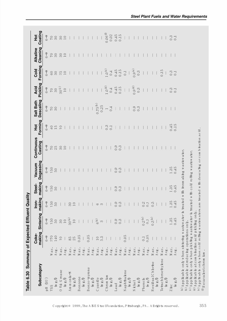
7/17/2019 Steel Plants Fuels and Water Consumption
http://slidepdf.com/reader/full/steel-plants-fuels-and-water-consumption 77/102
Steel Plant Fuels and Water Requirements
C opyright © 1999, The A IS E S teel Foundation, Pittsburgh, PA . A ll rights reserved. 355
T a b l e
6 . 3 0
S u m m a r y o f E x p e c t e d
E f f l u e n t Q u a l i t y
C o k e -
I r o n -
S t e e l -
V a c u u m
C o n t i n u o u s
H o t
S a l t B a t h
A c i d
C o l d
A l k a
l i n e
H o t
S u b
c a t e g o r y
m a k i n g
S i n
t e r i n g
m a k i n g
m a k i n g
D e g a s s i n g
C a s t i n g
F o r m i n g
D e s
c a l i n g
P i c k l i n g
F o r m i n g
C l e a
n i n g
C o a t i n g
p H ( S U
)
6 –
9
6 –
9
6 –
9
6 –
9
6 – 9
6 –
9
6 –
9
6 –
9
6 –
9
6 –
9
6 –
9
6 –
9
T S S
M a x .
2 7 0
1 5 0
1 5 0
1 5 0
1 5 0
7 0
4 0
7 0
7 0
6 0
7
0
7 0
( m g
/ l )
A v g .
1 4 0
5 0
5 0
5 0
5 0
2 5
1 5
3 0
3 0
3 0
3
0
3 0
O i l & G
r e a s e
M a x .
1 0
3 0
—
—
—
3 0
1 0
—
3 0 ( c )
2 5
3
0
3 0
( m g
/ l )
A v g .
—
1 0
—
—
—
1 0
—
—
1 0
1 0
1
0
1 0
A m m o
n i a –
N
M a x .
8 5
3
0 ( a )
3 0
—
—
—
—
—
—
—
—
—
( m g
/ l )
A v g .
2 5
1 0
1 0
—
—
—
—
—
—
—
—
—
B e n z e n e
M a x .
0 . 0
5
—
—
—
—
—
—
—
—
—
—
—
( m g
/ l )
A v g .
—
—
—
—
—
—
—
—
—
—
—
—
B e n z o – p y r e n e
M a x .
0 . 0
5
—
—
—
—
—
—
—
—
—
—
—
( m g
/ l )
A v g .
—
—
—
—
—
—
—
—
—
—
—
—
C y a n i d
e
M a x .
1 0
6 ( a )
6
—
—
—
—
0 . 7
5 ( b )
—
—
—
—
( m g
/ l )
A v g .
5 . 5
3
3
—
—
—
—
0 . 2
5
—
—
—
—
C h r o m
i u m
M a x .
—
—
—
—
—
—
0 . 3
1
1 . 0
( d )
1 . 0
( e )
—
0 . 0
6 ( f )
( m g
/ l )
A v g .
—
—
—
—
—
—
0 . 1
0 . 4
0 . 4
0 . 4
—
0 . 0
2
L e a
d
M a x .
—
0 . 9
0 . 9
0 . 9
0 . 9
0 . 9
—
—
0 . 4
5
0 . 4
5
—
0 . 4
5
( m g
/ l )
A v g .
—
0 . 3
0 . 3
0 . 3
0 . 3
0 . 3
—
—
0 . 1
5
0 . 1
5
—
0 . 1
5
N a p h t
h a
l e n e
M a x .
0 . 0
5
—
—
—
—
—
—
—
—
0 . 1
—
—
( m g
/ l )
A v g .
—
—
—
—
—
—
—
—
—
—
—
—
N i c k e l
M a x .
—
—
—
—
—
—
—
0 . 9
0 . 9
( d )
0 . 9
( e )
—
—
( m g
/ l )
A v g .
—
—
—
—
—
—
—
0 . 3
0 . 3
0 . 3
—
—
P h e n o
l s
M a x .
0 . 1
0
. 2 ( a )
0 . 2
—
—
—
—
—
—
—
—
—
( m g
/ l )
A v g .
0 . 0
5
0 . 1
0 . 1
—
—
—
—
—
—
—
—
—
R e s
i d u
a l C h l o r i n e
M a x .
—
0
. 5 ( a )
0 . 5
—
—
—
—
—
—
—
—
—
( m g
/ l )
A v g .
—
—
—
—
—
—
—
—
—
—
—
—
T e t r a c
h l o r o e
t h y
l e n e
M a x .
—
—
—
—
—
—
—
—
—
0 . 1
5
—
—
( m g
/ l )
A v g .
—
—
—
—
—
—
—
—
—
—
—
—
Z i n c
M a x .
—
1 . 3
5
1 . 3
5
1 . 3
5
1 . 3 5
—
0 . 4
5
—
0 . 3
0 . 3
—
0 . 3
( m g
/ l )
A v g .
—
0 . 4
5
0 . 4
5
0 . 4
5
0 . 4 5
—
0 . 1
5
—
0 . 1
0 . 1
—
0 . 1
( a ) A p p
l i c a
b l e o n
l y w
h e n s
i n t e r i n g w a s t e
w a
t e r
i s t r e a
t e d w
i t h i r o n m a
k i n g w
a s
t e w a
t e r .
( b ) A p p
l i c a
b l e a
t r e
d u c
i n g o p e r a
t i o n s o n
l y .
( c ) A p p
l i c a
b l e o n
l y w
h e n p
i c k l i n g w a s t e w
a t e r
i s t r e a
t e d w
i t h c o
l d r o
l l i n g w
a s
t e w a
t e r .
( d ) A p p
l i c a
b l e a
t c o m
b i n a
t i o n a c
i d p
i c k l i n g o n
l y .
( e ) A p p
l i c a
b l e o n
l y w
h e n c o
l d r o
l l i n g w a s
t e w a
t e r s a r e
t r e a
t e d w
i t h d e s c a l i n g o r c o m
b i n a
t i o n a c
i d .
( f ) H e x a v a
l e n
t c
h r o m
i u m .
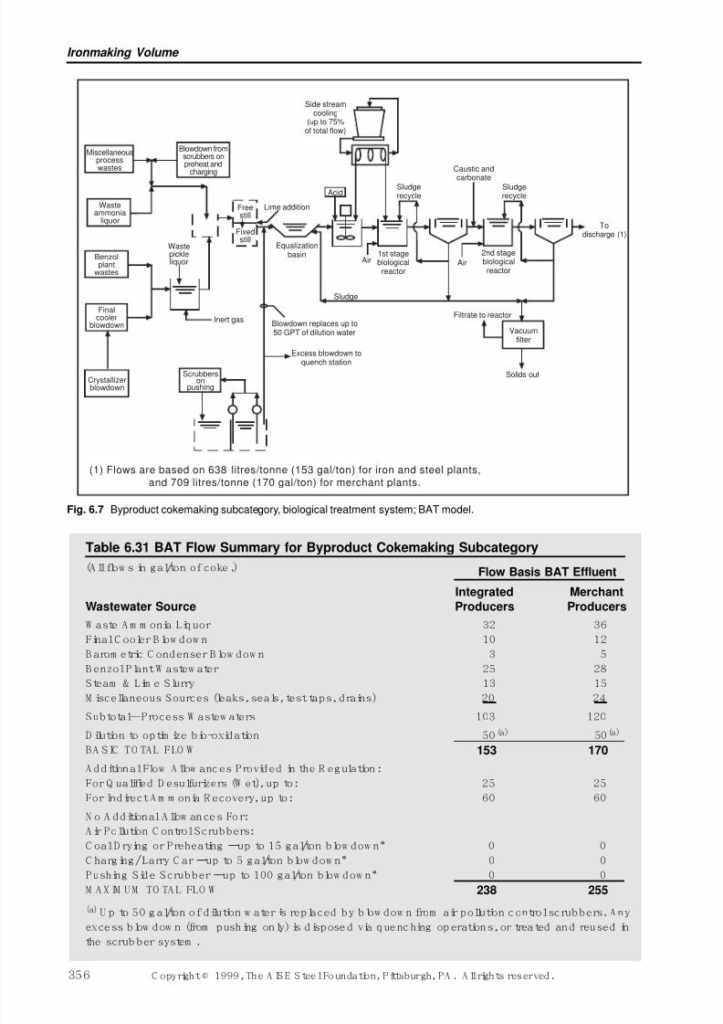
7/17/2019 Steel Plants Fuels and Water Consumption
http://slidepdf.com/reader/full/steel-plants-fuels-and-water-consumption 78/102
Ironmaking Volume
356 C opyright © 1999, The A IS E S teel Foundation, Pittsburgh, PA . A ll rights reserved.
Miscellaneousprocesswastes
Wasteammonia
liquor
Benzolplant
wastes
Finalcooler
blowdown
Crystallizerblowdown
Scrubberson
pushing
Wastepickleliquor
Inert gas
Freestill
Fixedstill
Blowdown fromscrubbers onpreheat and
charging
Lime addition
Equalizationbasin
Blowdown replaces up to50 GPT of dilution water
Excess blowdown toquench station
Sludge
Air1st stagebiologicalreactor
Sludgerecycle
Caustic and
carbonateSludgerecycle
Air
2nd stagebiologicalreactor
Todischarge (1)
Vacuumfilter
Solids out
Filtrate to reactor
Acid
Side streamcooling
(up to 75%of total flow)
(1) Flows are based on 638 litres/tonne (153 gal/ton) for iron and steel plants,
and 709 litres/tonne (170 gal/ton) for merchant plants.
Fig. 6.7 Byproduct cokemaking subcategory, biological treatment system; BAT model.
Table 6.31 BAT Flow Summary for Byproduct Cokemaking Subcategory
(A ll flow s in gal/ton of coke.) Flow Basis BAT Effluent
Integrated Merchant
Wastewater Source Producers Producers
W aste A m m onia Liquor 32 36
Final C ooler B low dow n 10 12
B arom etric C ondenser B low dow n 3 5
B enzol Plant W astew ater 25 28
Steam & Lim e Slurry 13 15
M iscellaneous Sources (leaks, seals, test taps, drains) 20 24
Subtotal—Process W astew aters 103 120D ilution to optim ize bio-oxidation 50(a) 50(a)
BA SIC TO TAL FLO W 153 170
A dditional Flow A llow ances Provided in the R egulation:
For Q ualified D esulfurizers (W et), up to: 25 25
For Indirect A m m onia R ecovery, up to: 60 60
N o A dditional A llow ances For:
A ir Pollution C ontrol Scrubbers:
C oal D rying or Preheating –up to 15 gal/ton blow dow n* 0 0
C harging/ Larry C ar –up to 5 gal/ton blow dow n* 0 0
Pushing Side Scrubber –up to 100 gal/ton blow dow n* 0 0
M AXIM UM TO TAL FLO W 238 255
(a) U p to 50 g al/ton of dilution w ater is replaced by blow dow n from air pollution control scrubbers. A ny
excess blow dow n (from pushing only) is disposed via quenching op erations, or treated and reused in
the scrub ber system .
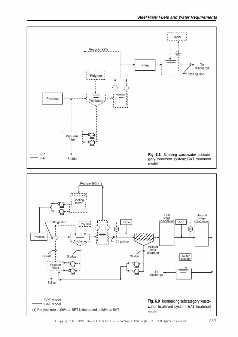
7/17/2019 Steel Plants Fuels and Water Consumption
http://slidepdf.com/reader/full/steel-plants-fuels-and-water-consumption 79/102
Steel Plant Fuels and Water Requirements
C opyright © 1999, The A IS E S teel Foundation, Pittsburgh, PA . A ll rights reserved. 357
BPT
BAT
Vacuumfilter
Process
Polymer
Recycle 92%
Filter
Acid
Todischarge
120 gal/ton
Thickener
Solids
pH
Fig. 6.8 Sintering wastewater subcate-
gory treatment system; BAT treatment
model.
BPT model
BAT model
(1) Recycle rate of 96% at BPT is increased to 98% at BAT.
Vacuumfilters
Solids
pH
Thickener
Process
Filtrate Sludge
Polymer3200 gal/ton
Coolingtower
Recycle 98% (1)
Lime
70 gal/ton
Sludge
Inclinedplate
separator
Todischarge
Sulfurdioxide
Secondstage
chlorinationAcid
Firststage
chlorination
pH
Fig. 6.9 Ironmaking subcategory waste-
water treatment system, BAT treatment
model.
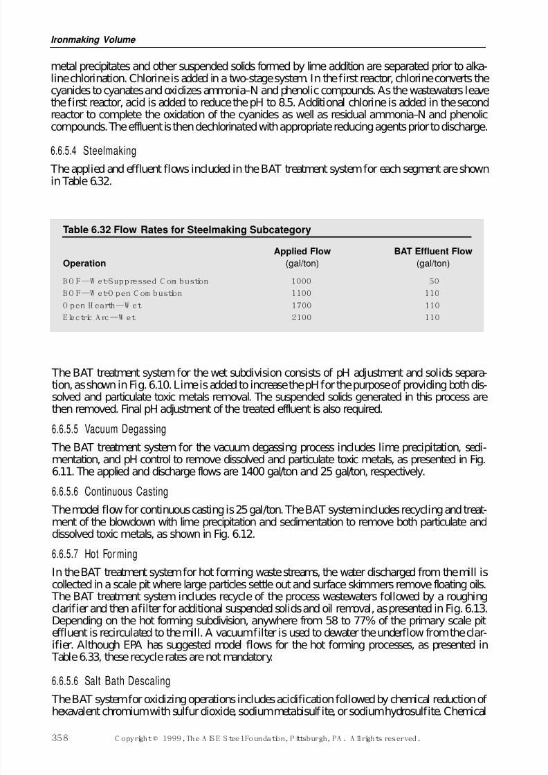
7/17/2019 Steel Plants Fuels and Water Consumption
http://slidepdf.com/reader/full/steel-plants-fuels-and-water-consumption 80/102
metal precipitates and other suspended solids formed by lime addition are separated prior to alka-line chlorination. Chlorine is added in a two-stage system. In the first reactor, chlorine converts thecyanides to cyanates and oxidizes ammonia–N and phenolic compounds. As the wastewaters leavethe first reactor, acid is added to reduce the pH to 8.5. Additional chlorine is added in the secondreactor to complete the oxidation of the cyanides as well as residual ammonia–N and phenoliccompounds. The effluent is then dechlorinated with appropriate reducing agents prior to discharge.
6.6.5.4 Steelmaking
The applied and effluent flows included in the BAT treatment system for each segment are shownin Table 6.32.
Ironmaking Volume
358 C opyright © 1999, The A IS E S teel Foundation, Pittsburgh, PA . A ll rights reserved.
Table 6.32 Flow Rates for Steelmaking Subcategory
Applied Flow BAT Effluent Flow
Operation (gal/ton) (gal/ton)
B O F—W et-Suppressed C om bustion 1000 50
B O F—W et-O pen C om bustion 1100 110
O pen H earth—W et 1700 110
Electric A rc—W et 2100 110
The BAT treatment system for the wet subdivision consists of pH adjustment and solids separa-tion, as shown in Fig. 6.10. Lime is added to increase the pH for the purpose of providing both dis-solved and particulate toxic metals removal. The suspended solids generated in this process are
then removed. Final pH adjustment of the treated effluent is also required.
6.6.5.5 Vacuum Degassing
The BAT treatment system for the vacuum degassing process includes lime precipitation, sedi-mentation, and pH control to remove dissolved and particulate toxic metals, as presented in Fig.6.11. The applied and discharge flows are 1400 gal/ton and 25 gal/ton, respectively.
6.6.5.6 Continuous Casting
The model flow for continuous casting is 25 gal/ton. The BAT system includes recycling and treat-ment of the blowdown with lime precipitation and sedimentation to remove both particulate anddissolved toxic metals, as shown in Fig. 6.12.
6.6.5.7 Hot For ming
In the BAT treatment system for hot forming waste streams, the water discharged from the mill iscollected in a scale pit where large particles settle out and surface skimmers remove floating oils. The BAT treatment system includes recycle of the process wastewaters followed by a roughingclarifier and then a filter for additional suspended solids and oil removal, as presented in Fig. 6.13.Depending on the hot forming subdivision, anywhere from 58 to 77% of the primary scale piteffluent is recirculated to the mill. A vacuum filter is used to dewater the underflow from the clar-ifier. Although EPA has suggested model flows for the hot forming processes, as presented in Table 6.33, these recycle rates are not mandatory.
6.6.5.6 Salt Bath Descaling
The BAT system for oxidizing operations includes acidification followed by chemical reduction of hexavalent chromium with sulfur dioxide, sodium metabisulf ite, or sodium hydrosulfite. Chemical
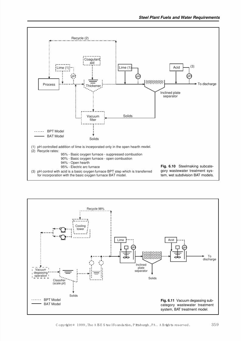
7/17/2019 Steel Plants Fuels and Water Consumption
http://slidepdf.com/reader/full/steel-plants-fuels-and-water-consumption 81/102
Steel Plant Fuels and Water Requirements
C opyright © 1999, The A IS E S teel Foundation, Pittsburgh, PA . A ll rights reserved. 359
pH pH pH
(3)
To discharge
Inclined plateseparator
Solids
Solids
Vacuum
filter
Thickener
Lime (1) Acid
Coagulantaid
Recycle (2)
Lime (1)
Process
(1) pH controlled addition of lime is incorporated only in the open hearth model.
(2) Recycle rates:95% - Basic oxygen furnace - suppressed combustion
90% - Basic oxygen furnace - open combustion
94% - Open hearth
95% - Electric arc furnace
(3) pH control with acid is a basic oxygen furnace BPT step which is transferredfor incorporation with the basic oxygen furnace BAT model.
BPT Model
BAT Model
Fig. 6.10 Steelmaking subcate-
gory wastewater treatment sys-
tem, wet subdivision BAT models.
Todischarge
Acid
Solids
Inclinedplate
separator
pHpH
Recycle 98%
Coolingtower
Vacuumdegassingoperation
Classifier(scale pit)
Solids
Lime
BPT ModelBAT Model
Fig. 6.11 Vacuum degassing sub-
category wastewater treatment
system, BAT treatment model.
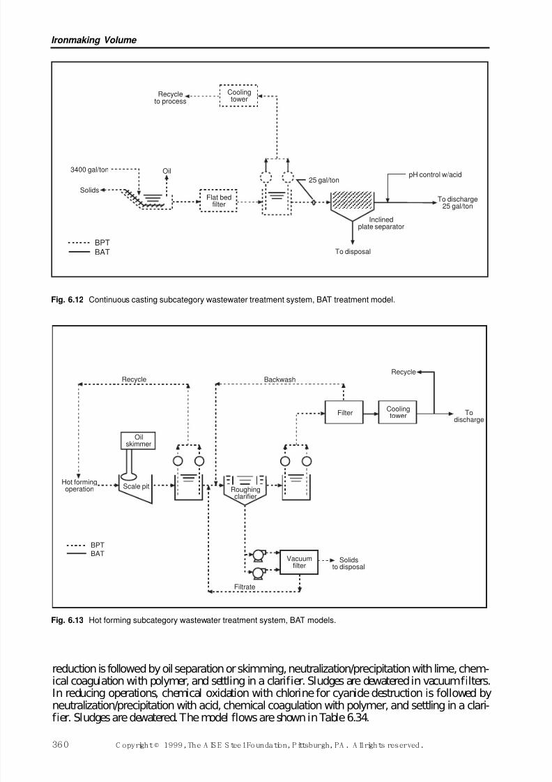
7/17/2019 Steel Plants Fuels and Water Consumption
http://slidepdf.com/reader/full/steel-plants-fuels-and-water-consumption 82/102
Ironmaking Volume
360 C opyright © 1999, The A IS E S teel Foundation, Pittsburgh, PA . A ll rights reserved.
3400 gal/ton
Solids
Oil
Flat bedfilter
25 gal/ton
To disposal
Inclinedplate separator
pH control w/acid
To discharge25 gal/ton
Coolingtower
Recycleto process
BPT
BAT
Fig. 6.12 Continuous casting subcategory wastewater treatment system, BAT treatment model.
Hot formingoperation Scale pit
Oilskimmer
Recycle
Filter
Solidsto disposal
Filtrate
Vacuumfilter
Roughingclarifier
Coolingtower
Recycle
Todischarge
Backwash
BPTBAT
Fig. 6.13 Hot forming subcategory wastewater treatment system, BAT models.
reduction is followed by oil separation or skimming, neutralization/precipitation with lime, chem-
ical coagulation with polymer, and settling in a clarifier. Sludges are dewatered in vacuum filters.In reducing operations, chemical oxidation with chlorine for cyanide destruction is followed byneutralization/precipitation with acid, chemical coagulation with polymer, and settling in a clari-fier. Sludges are dewatered. The model flows are shown in Table 6.34.
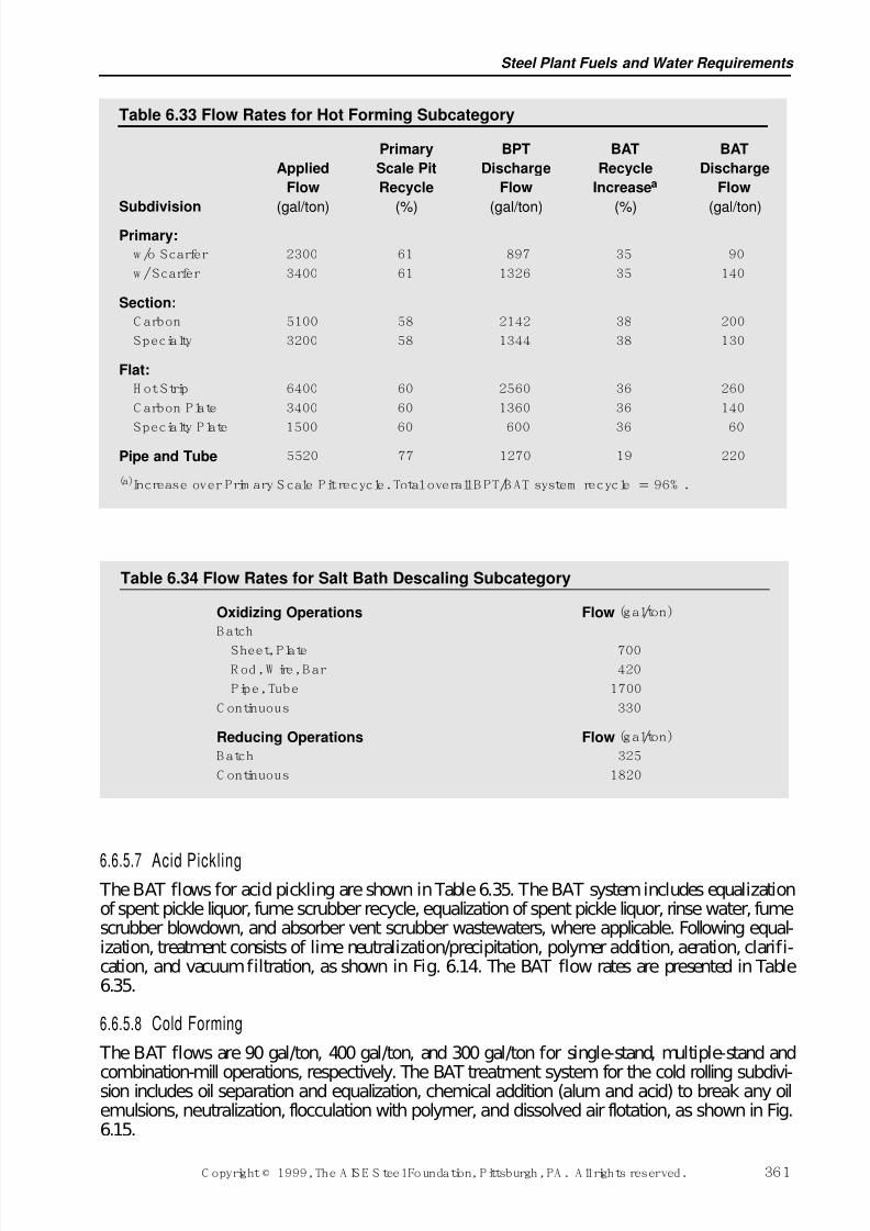
7/17/2019 Steel Plants Fuels and Water Consumption
http://slidepdf.com/reader/full/steel-plants-fuels-and-water-consumption 83/102
6.6.5.7 Acid Pickling The BAT flows for acid pickling are shown in Table 6.35. The BAT system includes equalizationof spent pickle liquor, fume scrubber recycle, equalization of spent pickle liquor, rinse water, fumescrubber blowdown, and absorber vent scrubber wastewaters, where applicable. Following equal-ization, treatment consists of lime neutralization/precipitation, polymer addition, aeration, clarifi-cation, and vacuum filtration, as shown in Fig. 6.14. The BAT flow rates are presented in Table6.35.
6.6.5.8 Cold Forming
The BAT flows are 90 gal/ton, 400 gal/ton, and 300 gal/ton for single-stand, multiple-stand and
combination-mill operations, respectively. The BAT treatment system for the cold rolling subdivi-sion includes oil separation and equalization, chemical addition (alum and acid) to break any oilemulsions, neutralization, flocculation with polymer, and dissolved air flotation, as shown in Fig.6.15.
Table 6.34 Flow Rates for Salt Bath Descaling Subcategory
Oxidizing Operations Flow (gal/ton)
B atch
Sheet, Plate 700R od, W ire, B ar 420
Pipe, Tube 1700
C ontinuous 330
Reducing Operations Flow (gal/ton)
B atch 325
C ontinuous 1820
Steel Plant Fuels and Water Requirements
C opyright © 1999, The A IS E S teel Foundation, Pittsburgh, PA . A ll rights reserved. 361
Table 6.33 Flow Rates for Hot Forming Subcategory
Primary BPT BAT BAT
Applied Scale Pit Discharge Recycle Discharge
Flow Recycle Flow Increasea Flow
Subdivision (gal/ton) (%) (gal/ton) (%) (gal/ton)
Primary:
w /o Scarfer 2300 61 897 35 90
w / Scarfer 3400 61 1326 35 140
Section:
C arbon 5100 58 2142 38 200
Specialty 3200 58 1344 38 130
Flat:
H ot Strip 6400 60 2560 36 260
C arbon Plate 3400 60 1360 36 140
Specialty Plate 1500 60 600 36 60
Pipe and Tube 5520 77 1270 19 220
(a)Increase over Prim ary S cale Pit recycle. Total overall B PT/B AT system recycle 96% .
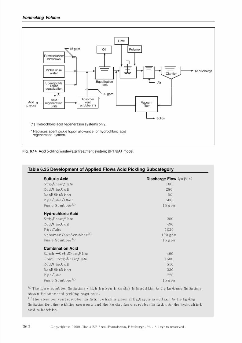
7/17/2019 Steel Plants Fuels and Water Consumption
http://slidepdf.com/reader/full/steel-plants-fuels-and-water-consumption 84/102
Ironmaking Volume
362 C opyright © 1999, The A IS E S teel Foundation, Pittsburgh, PA . A ll rights reserved.
(1) Hydrochloric acid regeneration systems only.
* Replaces spent pickle liquor allowance for hydrochloric acidregeneration system.
Spent pickleliquor
equalization
(1)
Pickle rinsewater
Fume scrubber
blowdown
Acidto reuse
Absorbervent
scrubber (1)
*
15 gpm Oil
Equalizationtank
100 gpm
Lime
Polymer
ClarifierTo discharge
Air
Vacuumfilter
Solids
Acidregeneration
units
Fig. 6.14 Acid pickling wastewater treatment system; BPT/BAT model.
Table 6.35 Development of Applied Flows Acid Pickling Subcategory
Sulfuric Acid Discharge Flow (gal/ton)Strip/Sheet/Plate 180
R od/W ire/C oil 280
B ar/B illet/B loom 90
Pipe/Tube/O ther 500
Fum e Scrubber(a) 15 gpm
Hydrochloric Acid
Strip/Sheet/Plate 280
R od/W ire/C oil 490
Pipe/Tube 1020
A bsorber Vent Scrubber(b) 100 gpm
Fum e Scrubber(a) 15 gpm
Combination Acid
B atch –Strip/Sheet/Plate 460
C ont. –Strip/Sheet/Plate 1500
R od/W ire/C oil 510
B ar/B illet/B loom 230
Pipe/Tube 770
Fum e Scrubber(a) 15 gpm
(a) The fum e scrubber lim itations w hich is g iven in K g/day is in addition to the kg/tonne lim itations
show n for other acid pickling segm ents.(b)
The absorber vent scrubber lim itation, w hich is given in K g/day, is in addition to the kg/K kglim itation for other pickling segm ents and the K g/day fum e scrubber lim itation for the hydrochloric
acid subdivision.
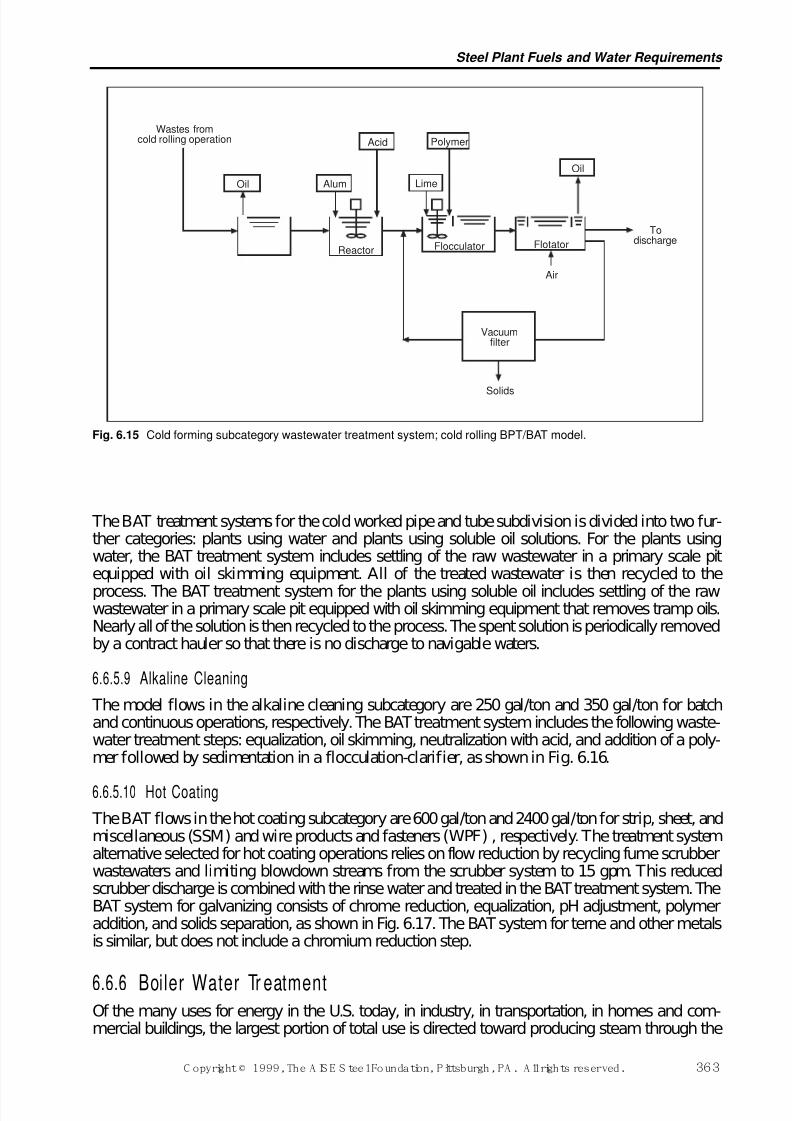
7/17/2019 Steel Plants Fuels and Water Consumption
http://slidepdf.com/reader/full/steel-plants-fuels-and-water-consumption 85/102
Steel Plant Fuels and Water Requirements
C opyright © 1999, The A IS E S teel Foundation, Pittsburgh, PA . A ll rights reserved. 363
The BAT treatment systems for the cold worked pipe and tube subdivision is divided into two fur-ther categories: plants using water and plants using soluble oil solutions. For the plants usingwater, the BAT treatment system includes settling of the raw wastewater in a primary scale pitequipped with oil skimming equipment. All of the treated wastewater is then recycled to the
process. The BAT treatment system for the plants using soluble oil includes settling of the rawwastewater in a primary scale pit equipped with oil skimming equipment that removes tramp oils.Nearly all of the solution is then recycled to the process. The spent solution is periodically removedby a contract hauler so that there is no discharge to navigable waters.
6.6.5.9 Alkaline Cleaning
The model flows in the alkaline cleaning subcategory are 250 gal/ton and 350 gal/ton for batchand continuous operations, respectively. The BAT treatment system includes the following waste-water treatment steps: equalization, oil skimming, neutralization with acid, and addition of a poly-mer followed by sedimentation in a flocculation-clarifier, as shown in Fig. 6.16.
6.6.5.10 Hot Coating
The BAT flows in the hot coating subcategory are 600 gal/ton and 2400 gal/ton for strip, sheet, andmiscellaneous (SSM) and wire products and fasteners (WPF) , respectively. The treatment systemalternative selected for hot coating operations relies on flow reduction by recycling fume scrubberwastewaters and limiting blowdown streams from the scrubber system to 15 gpm. This reducedscrubber discharge is combined with the rinse water and treated in the BAT treatment system. TheBAT system for galvanizing consists of chrome reduction, equalization, pH adjustment, polymeraddition, and solids separation, as shown in Fig. 6.17. The BAT system for terne and other metalsis similar, but does not include a chromium reduction step.
6.6.6 Boiler Water Tr eatmentOf the many uses for energy in the U.S. today, in industry, in transportation, in homes and com-mercial buildings, the largest portion of total use is directed toward producing steam through the
Wastes fromcold rolling operation
Reactor
Oil Alum
Acid
Lime
Oil
Flotator
Todischarge
Air
Vacuumfilter
Flocculator
Solids
Polymer
Fig. 6.15 Cold forming subcategory wastewater treatment system; cold rolling BPT/BAT model.
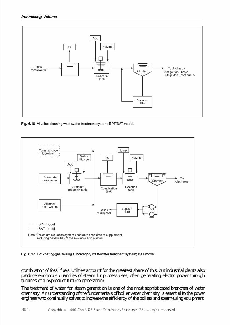
7/17/2019 Steel Plants Fuels and Water Consumption
http://slidepdf.com/reader/full/steel-plants-fuels-and-water-consumption 86/102
combustion of fossil fuels. Utilities account for the greatest share of this, but industrial plants alsoproduce enormous quantities of steam for process uses, often generating electric power throughturbines of a byproduct fuel (co-generation).
The treatment of water for steam generation is one of the most sophisticated branches of waterchemistry. An understanding of the fundamentals of boiler water chemistry is essential to the powerengineer who continually strives to increase the efficiency of the boilers and steam-using equipment.
Ironmaking Volume
364 C opyright © 1999, The A IS E S teel Foundation, Pittsburgh, PA . A ll rights reserved.
Rawwastewater
Oil
Acid
Polymer
Reactiontank
Clarifier
Vacuumfilter
To discharge
250 gal/ton - batch350 gal/ton - continuous
Fig. 6.16 Alkaline cleaning wastewater treatment system; BPT/BAT model.
Fume scrubberblowdown
Acid
Sulfurdioxide
Chromaterinse water
All otherrinse waters
Chromiumreduction tank
Oil Polymer
Lime
Vacuumfilter
Solidsto disposal
ClarifierTo
discharge
Equalizationtank
Reactiontank
BPT model
BAT model
Note: Chromium reduction system used only if required to supplementreducing capabilities of the available acid wastes.
Fig. 6.17 Hot coating/galvanizing subcategory wastewater treatment system; BAT model.
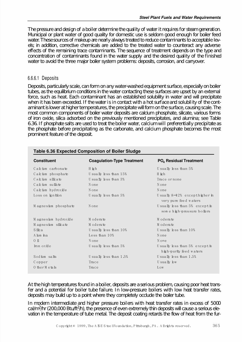
7/17/2019 Steel Plants Fuels and Water Consumption
http://slidepdf.com/reader/full/steel-plants-fuels-and-water-consumption 87/102
The pressure and design of a boiler determine the quality of water it requires for steam generation.Municipal or plant water of good quality for domestic use is seldom good enough for boiler feedwater. These sources of makeup are nearly always treated to reduce contaminants to acceptable lev-els; in addition, corrective chemicals are added to the treated water to counteract any adverseeffects of the remaining trace contaminants. The sequence of treatment depends on the type andconcentration of contaminants found in the water supply and the desired quality of the finished
water to avoid the three major boiler system problems: deposits, corrosion, and carryover.
6.6.6.1 Deposits
Deposits, particularly scale, can form on any water-washed equipment surface, especially on boilertubes, as the equilibrium conditions in the water contacting these surfaces are upset by an externalforce, such as heat. Each contaminant has an established solubility in water and will precipitatewhen it has been exceeded. If the water is in contact with a hot surface and solubility of the cont-aminant is lower at higher temperatures, the precipitate will form on the surface, causing scale. Themost common components of boiler water deposits are calcium phosphate, silicate, various forms
of iron oxide, silica adsorbed on the previously mentioned precipitates, and alumina; see Table6.36. If phosphate salts are used to treat the boiler water, calcium will preferentially precipitate asthe phosphate before precipitating as the carbonate, and calcium phosphate becomes the mostprominent feature of the deposit.
At the high temperatures found in a boiler, deposits are a serious problem, causing poor heat trans-fer and a potential for boiler tube failure. In low-pressure boilers with low heat transfer rates,deposits may build up to a point where they completely occlude the boiler tube.
In modern intermediate and higher pressure boilers with heat transfer rates in excess of 5000cal/m2/hr (200,000 Btu/ft2/h), the presence of even extremely thin deposits will cause a serious ele-vation in the temperature of tube metal. The deposit coating retards the flow of heat from the fur-
Table 6.36 Expected Composition of Boiler Sludge
Constituent Coagulation-Type Treatment PO4 Residual Treatment
C alcium carbonate H igh U sually less than 5%
C alcium phosphate U sually less than 15% H igh
C alcium silicate U sually less than 3% Trace or noneC alcium sulfate N one N one
C alcium hydroxide N one N one
Loss on Ignition U sually less than 5% U sually 8–12% except higher in
very pure feed w aters
M agnesium phosphate N one U sually less than 5% except in
som e high-pressure boilers
M agnesium hydroxide M oderate M oderate
M agnesium silicate M oderate M oderate
Silica U sually less than 10% U sually less than 10%
A lum ina Less than 10% N one
O il N one N oneIron oxide U sually less than 5% U sually less than 5% except in
high-purity feed w aters
Sodium salts U sually less than 1.5% U sually less than 1.5%
C opper Trace U sually low
O ther M etals Trace Low
Steel Plant Fuels and Water Requirements
C opyright © 1999, The A IS E S teel Foundation, Pittsburgh, PA . A ll rights reserved. 365
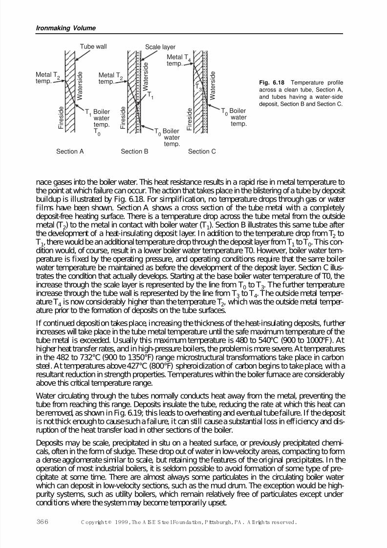
7/17/2019 Steel Plants Fuels and Water Consumption
http://slidepdf.com/reader/full/steel-plants-fuels-and-water-consumption 88/102
nace gases into the boiler water. This heat resistance results in a rapid rise in metal temperature to
the point at which failure can occur. The action that takes place in the blistering of a tube by depositbuildup is illustrated by Fig. 6.18. For simplification, no temperature drops through gas or waterfilms have been shown. Section A shows a cross section of the tube metal with a completelydeposit-free heating surface. There is a temperature drop across the tube metal from the outsidemetal (T2) to the metal in contact with boiler water (T1). Section B illustrates this same tube afterthe development of a heat-insulating deposit layer. In addition to the temperature drop from T2 to T1, there would be an additional temperature drop through the deposit layer from T1 to T0. This con-dition would, of course, result in a lower boiler water temperature T0. However, boiler water tem-perature is fixed by the operating pressure, and operating conditions require that the same boilerwater temperature be maintained as before the development of the deposit layer. Section C illus-trates the condition that actually develops. Starting at the base boiler water temperature of T0, the
increase through the scale layer is represented by the line from T0 to T3. The further temperatureincrease through the tube wall is represented by the line from T3 to T4. The outside metal temper-ature T4 is now considerably higher than the temperature T2, which was the outside metal temper-ature prior to the formation of deposits on the tube surfaces.
If continued deposition takes place, increasing the thickness of the heat-insulating deposits, furtherincreases will take place in the tube metal temperature until the safe maximum temperature of thetube metal is exceeded. Usually this maximum temperature is 480 to 540°C (900 to 1000°F). Athigher heat transfer rates, and in high-pressure boilers, the problem is more severe. At temperaturesin the 482 to 732°C (900 to 1350°F) range microstructural transformations take place in carbonsteel. At temperatures above 427°C (800°F) spheroidization of carbon begins to take place, with aresultant reduction in strength properties. Temperatures within the boiler furnace are considerably
above this critical temperature range.Water circulating through the tubes normally conducts heat away from the metal, preventing thetube from reaching this range. Deposits insulate the tube, reducing the rate at which this heat canbe removed, as shown in Fig. 6.19; this leads to overheating and eventual tube failure. If the depositis not thick enough to cause such a failure, it can still cause a substantial loss in efficiency and dis-ruption of the heat transfer load in other sections of the boiler.
Deposits may be scale, precipitated in situ on a heated surface, or previously precipitated chemi-cals, often in the form of sludge. These drop out of water in low-velocity areas, compacting to forma dense agglomerate similar to scale, but retaining the features of the original precipitates. In theoperation of most industrial boilers, it is seldom possible to avoid formation of some type of pre-
cipitate at some time. There are almost always some particulates in the circulating boiler waterwhich can deposit in low-velocity sections, such as the mud drum. The exception would be high-purity systems, such as utility boilers, which remain relatively free of particulates except underconditions where the system may become temporarily upset.
Ironmaking Volume
366 C opyright © 1999, The A IS E S teel Foundation, Pittsburgh, PA . A ll rights reserved.
Metal T2
temp.
Tube wall
F i r e s i d e
W
a t e r s i d e Metal T
2temp.
F i r e s i d e
T1 Boilerwatertemp.T
0T
0 Boilerwatertemp.
T1
W a t e r s i d e
Scale layer
Metal T4
temp.
F i r e s i d e T
0 Boilerwatertemp.
W
a t e r s i d e
T3
Section A Section B Section C
Fig. 6.18 Temperature profile
across a clean tube, Section A,
and tubes having a water-sidedeposit, Section B and Section C.
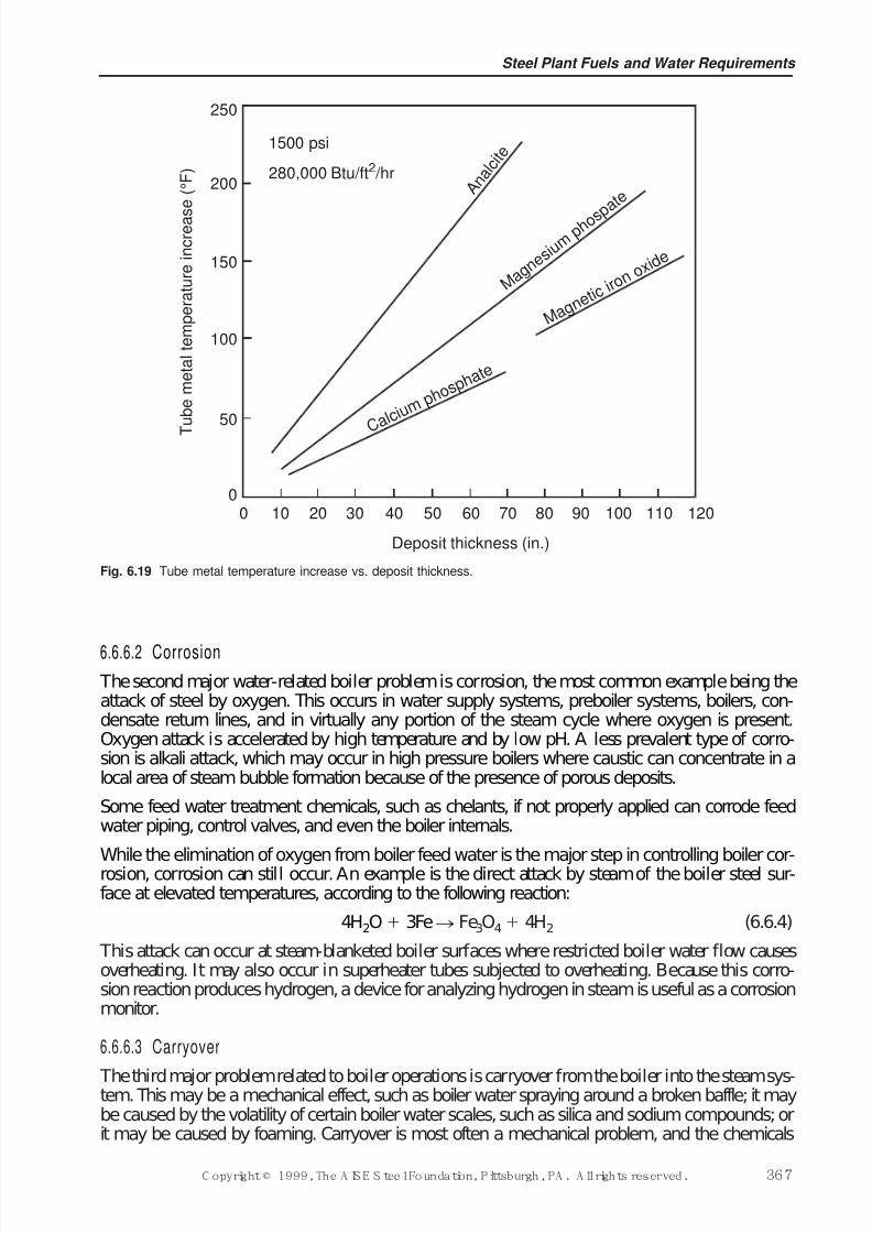
7/17/2019 Steel Plants Fuels and Water Consumption
http://slidepdf.com/reader/full/steel-plants-fuels-and-water-consumption 89/102
6.6.6.2 Corrosion
The second major water-related boiler problem is corrosion, the most common example being theattack of steel by oxygen. This occurs in water supply systems, preboiler systems, boilers, con-densate return lines, and in virtually any portion of the steam cycle where oxygen is present.Oxygen attack is accelerated by high temperature and by low pH. A less prevalent type of corro-sion is alkali attack, which may occur in high pressure boilers where caustic can concentrate in alocal area of steam bubble formation because of the presence of porous deposits.
Some feed water treatment chemicals, such as chelants, if not properly applied can corrode feedwater piping, control valves, and even the boiler internals.
While the elimination of oxygen from boiler feed water is the major step in controlling boiler cor-rosion, corrosion can still occur. An example is the direct attack by steam of the boiler steel sur-face at elevated temperatures, according to the following reaction:
4H2O 3Fen Fe3O4 4H2 (6.6.4)
This attack can occur at steam-blanketed boiler surfaces where restricted boiler water flow causesoverheating. It may also occur in superheater tubes subjected to overheating. Because this corro-sion reaction produces hydrogen, a device for analyzing hydrogen in steam is useful as a corrosionmonitor.
6.6.6.3 Carryover
The third major problem related to boiler operations is carryover from the boiler into the steam sys-tem. This may be a mechanical effect, such as boiler water spraying around a broken baffle; it maybe caused by the volatility of certain boiler water scales, such as silica and sodium compounds; orit may be caused by foaming. Carryover is most often a mechanical problem, and the chemicals
Steel Plant Fuels and Water Requirements
C opyright © 1999, The A IS E S teel Foundation, Pittsburgh, PA . A ll rights reserved. 367
T
u b e m e t a l t e m p e r a t u r e i n c r e a s
e ( ° F )
Deposit thickness (in.)
0 10 20 30 40 50 60 70 80 90 100 110 120
250
200
150
100
50
0
A n a l c i t e
M a g n
e s i u m
p h o s p a t e
M a g n e
t i c i r o n
o x i d e
C a l c i
u m p h o s p
h a t e
1500 psi
280,000 Btu/ft2 /hr
Fig. 6.19 Tube metal temperature increase vs. deposit thickness.
7/17/2019 Steel Plants Fuels and Water Consumption
http://slidepdf.com/reader/full/steel-plants-fuels-and-water-consumption 90/102
found in the steam are those originally present in the boiler water, plus the volatile components thatdistill from the boiler even in the absence of spray.
There are three basic means for keeping these major problems under control. External treatment of makeup water, condensate, or both, is performed before their entry into the boiler to reduce oreliminate chemicals (such as hardness or silica), gases or solids. Internal treatment of the boiler
feed water, boiler water, steam, or condensate with corrective chemicals may be performed.Control of the concentration of chemicals in the boiler water may be performed by blowdown of the water from the boiler.
6.6.6.4 Exter nal Tr eatment
Most of the unit operations of water treatment can be used alone or in combination with others toadapt any water supply to any boiler system. The suitability of the processes available is judged bythe results they produce and the costs involved. Water treatment processes include: sodium zeolitesoftening, lime softening, lime softening followed by sodium zeolite softening, split stream deal-kalization, demineralization, and reverse osmosis.
The boiler treatment program aims at control of seven broad classifications of impurities: sus-pended solids, hardness, alkalinity, silica, total dissolved solids (TDS), organic matter, and gases.
6.6.6.4.1 Suspended Solids The removal of suspended solids is accomplished by coagulation/floc-culation, filtration, or precipitation. Just about all unit processes require prior removal of solids.For example, water to be processed by ion exchange should contain less that 10 mg/litre suspendedsolids to avoid fouling of the exchanger and operating problems.
6.6.6.4.2 Hardness A number of unit operations can remove calcium and magnesium from water,as well as other impurities. Partial cold lime softening and complete hot lime softening are used inmost heavy industrial plants. These processes remove hardness, alkalinity, silica, and suspendedsolids. Sodium exchange can be used alone or in conjunction with lime softening.
6.6.6.4.3 Alkalinity It is desirable to have some alkalinity in boiler water, so complete removal of alkalinity from boiler makeup is seldom practiced except in demineralization. Some alkalinity isalso needed to provide optimum pH in the feed water to prevent corrosion if piping and equipment.
The makeup alkalinity may be present as HCO3–, CO3
2–, or OH–. If the makeup is city water thathas been zeolite softened, alkalinity is usually in the bicarbonate (HCO3
–) form; if lime softened,it is mostly carbonate (CO3
2–), but the water may also contain some hydroxide (OH–). When bicar-bonates and carbonates are exposed to boiler temperatures, they break down to release CO2:
2NaHCO3n Na2CO3 H2O CO2 (6.6.5)
The sodium carbonate then breaks down further to caustic:
Na2CO3 H2On 2NaOH CO2 (6.6.6) The carbon dioxide gas redissolves when the steam condenses, producing corrosive carbonic acid:
CO2 H2On H HCO3– (6.6.7)
The amount of CO2 generated is proportional to alkalinity. For a given alkalinity twice as muchCO2 is formed from HCO3
– as from CO32– because the bicarbonate breakdown is the sum of both
reactions 6.6.5 and 6.6.7 above. The carbonic acid is usually neutralized by chemical treatment of the steam, either directly or indirectly through the boiler, to produce a condensate pH in the rangeof 8.5 to 9.0. Reduction of feed water alkalinity is desirable, then, to minimize CO2 formation andreduce chemical treatment costs.
The hydroxide produced by the breakdown of HCO3
–
and CO3
2–
is beneficial for precipitation of magnesium, to provide a good environment for sludge conditioning, and to minimize SiO2 carry-over. However, too high an excess of caustic can be corrosive, particularly if localized concentra-tion can occur. The breakdown of HCO3
– is complete, but not all the CO32– converts to caustic. The
Ironmaking Volume
368 C opyright © 1999, The A IS E S teel Foundation, Pittsburgh, PA . A ll rights reserved.
7/17/2019 Steel Plants Fuels and Water Consumption
http://slidepdf.com/reader/full/steel-plants-fuels-and-water-consumption 91/102
conversion varies from one boiler to another and increases with temperature. As a general rule, at600 lb/in2 65 to 85% of boiler water alkalinity is NaOH, the remainder being Na2CO3. (This isbased on the equilibrium in the cooled sample of boiler water).
The degree of alkalinity reduction is therefore dictated by boiler water control limits and steamquality goals. The best unit process for alkalinity reduction may be chosen for the other benefits it
provides as well as its efficiency in alkalinity reduction
6.6.6.4.4 Silica The permissible concentrations of silica in boiler water at various operating pres-sures are given in Table 6.37. Silica reduction is not always necessary, especially in the absence of a condensing turbine. Low concentrations of silica can be sometimes produce sticky sludge in low-pressure boilers treated with phosphate. A makeup treatment process may be selected to provide just the proper degree of silica reduction required by the steam system.
6.6.6.4.5 Total Dissolved Solids Some treatment processes increase dissolved solids by adding solu-ble byproducts to water; sodium zeolite softening increases solids by adding an ion (sodium) hav-ing a higher equivalent weight (23) than calcium (20) or magnesium (12.2) removed from the rawwater. Processes to reduce dissolved solids achieve various degrees of success. Usually, reductionof dissolved solids is accomplished by a reduction of several individual contaminants.
6.6.6.4.6 Organic Matter Organic matter as a general classif ication is only a qualitative term. Itincludes a wide variety of compounds that are seldom analyzed as specific materials. Problems inboiler systems attributed to organic matter have often been traced to organic materials from plantprocesses in returned condensate, rather than makeup water contaminants. However, in higherpressure utility systems, organic matter is the major impurity in makeup and can result in forma-
tion of organic acids.
6.6.6.4.7 Dissolved Gases Degasifiers are commonly used to remove gas mechanically rather thanchemically. Blower types are used for CO2 removal at ambient temperatures following acid orhydrogen-exchange units. Vacuum degasifiers provide the same extent of CO2 removal, but alsoreduce O2 to less than 0.5 to 1.0 mg/litre, offering corrosion protection, especially if the vacuumdegasifier is part of a demineralizing system. Steam-scrubbing degasifiers, call deaerating heaters,usually produce an effluent free of CO2with O2concentrations in the range of 0.005 to 0.01 mg/litre.Direct reaction of this low residual with catalyzed sulfite, hydrazine, or hydrazine substitutes (all-volatile oxygen-reducing compounds) eliminates O2 completely to prevent preboiler corrosion.
6.6.6.5 Condensate Retur ns
In addition to makeup treatment, acceptable feed water quality may require cleanup of condensateto protect the boiler system, particularly if there is process condensate containing oil. Boilers
Table 6.37 Permissible Concentrations of Silica in Boiler Water at VariousOperating Pressures
Silica concentration, (mg/litres)
Drum pressure, (lb/in2) Recommended To produce 0.02 mg/litre
0–300 150 150
301–450 90 90
451–600 40 55
601–750 30 35
751–900 20 20
900–1000 8 15
Steel Plant Fuels and Water Requirements
C opyright © 1999, The A IS E S teel Foundation, Pittsburgh, PA . A ll rights reserved. 369
7/17/2019 Steel Plants Fuels and Water Consumption
http://slidepdf.com/reader/full/steel-plants-fuels-and-water-consumption 92/102
requiring high-quality demineralized water also demand high-quality condensate. Some plantsoperate both high- and low-pressure boilers; high-quality feed water for the high pressure boilersmay be provided entirely by a demineralizer, with lower quality condensate segregated for returnto the low-pressure boilers.
Septum filters are usually selected for oily condensate treatment. A cellulose type filter aid
(processed wood pulp) is applied both as a precoat and a body feed. The temperature should be lessthan 93°C (200°F) to avoid degradation of the filter aid. Anthracite filters precoated with a flocproduced from alum and sodium aluminate are also effective. However, the pH of the condensatemust be controlled in the range of 7.0 to 8.0 to avoid solubilizing the alumina floc. Condensate con-taminated with corrosion products and inleakage of hard water is cleaned up through speciallydesigned, high flow rate sodium exchangers. They have been used to process condensate at tem-peratures up to 149°C (300°F). One serious limitation of the simple sodium exchanger is its abil-ity to pick up neutralizing amines such as morpholine (present in the condensate as morpholinebicarbonate) and exchange this for sodium. This causes excessive use of amines, but a more seri-ous problem arises if the condensate is returned to a high-pressure boiler where the presence of sodium may be objectionable in deterioration of steam quality. Special regeneration procedures
would then be needed.
6.6.6.6 Inter nal Tr eatment
Scale formation within a boiler is controlled by one of four chemical programs: coagulation (car-bonate), phosphate residual, chelation, or coordinated phosphate.
6.6.6.6.1 Coagulation Program In this process, sodium carbonate, sodium hydroxide, or both areadded to the boiler water to supplement the alkalinity supplied by the makeup, which is not soft-ened. The carbonate causes deliberate precipitation of calcium carbonate under favorable, con-trolled conditions, preventing deposition at some subsequent point as scale. Under alkalineconditions, magnesium and silica are also precipitated as magnesium hydroxide and magnesium
silicate. There is usually a fairly high concentration of suspended solids in the boiler water, and theprecipitation occurs on these solids. This method of treatment is used only with boilers (usuallyfiretube design) using high-hardness feed water and operating below 250 lb/in2(17 bars). This typeof treatment must be supplemented by some form of sludge conditioner. Even with a supplemen-tal sludge conditioner, heat transfer is hindered by deposit formation, and blowdown rates areexcessive because of high suspended solids. Coagulation programs are becoming obsolete as pre-treatment systems become more common and competitive with the high internal treatment cost.
6.6.6.6.2 Phosphate Program Where the boiler pressure is above 250 lb/in2, high concentrations of sludge are undesirable. In these boilers, feed water hardness should be limited to 60 mg/litre, andphosphate programs are preferred. Phosphate is also a common treatment below 250 lb/in2 with
soft makeup.A sodium phosphate compound is fed either to the boiler feed water or to the boiler drug, depend-ing on water analysis and the preboiler auxiliaries, to form an insoluble precipitate, principallyhydroxyapatite, Ca10(PO4)6(OH)2. Magnesium and silica are precipitated as magnesium hydroxide,magnesium silicate (often combined as 3MgO2SiO22H2O), or calcium silicate. The alkalinity of the makeup is usually adequate to produce the OH– for the magnesium precipitation. Phosphateresidual programs which produce high suspended solids require the addition of a sludge condi-tioner/dispersant. Because these programs restrict heat transfer, owing to the deposition of calciumand magnesium salts, precipitation programs of this type are often replaced with solubilizing treat-ments such as chelants and polymer/dispersants.
6.6.6.6.3Chelant Programs A chelate is a molecule similar to an ion exchanger; it is low in molec-ular weight and soluble in water. The sodium salts of ethylene diamine tetraacetic acid (EDTA) and
nitrilotriacetic acid (NTA) are the chelating agents most commonly used for internal boiler treat-ment. These chelate (form complex ions with) calcium and magnesium. Because the resulting com-
Ironmaking Volume
370 C opyright © 1999, The A IS E S teel Foundation, Pittsburgh, PA . A ll rights reserved.
7/17/2019 Steel Plants Fuels and Water Consumption
http://slidepdf.com/reader/full/steel-plants-fuels-and-water-consumption 93/102
plex is soluble, this treatment is advantageous in minimizing blowdown. The higher cost comparedto phosphate usually limits the use of chelates to feed waters having low hardness. There is the riskthat breakdown of the organic molecule at higher temperatures could create a potential problem of control that could result in corrosion, so chelate programs are usually limited to boilers operatingbelow 1500 lb/in2 (100 bars). The addition of polymers as scale control agents increases the effec-tiveness of chelate programs. It also reduces the corrosion potential by reducing the chelant dosage
below theoretical requirements, so that there is no chelant residual in the boiler water.
Chelates can react with oxygen under boiler water conditions, which can increase the cost of achelate program substantially. Overfeed of chelates and concentration mechanisms in the boiler canlead to severe localized corrosion and subsequent unit failure.
6.6.6.6.4 Coordinated Phosphate Program In high-pressure, high heat transfer rate boilers, the inter-nal treatment program must contribute little or no solids. The potential for caustic attack of boilermetal increases with increasing pressure, so free caustic alkalinity must be minimized. The coor-dinated phosphate program is chosen for these conditions. This differs from the standard programin that the phosphate is added to provide a controlled pH range in the boiler water as well as to
react with calcium if hardness should enter the boiler. Trisodium phosphate hydrolyzes to producehydroxide ions:
Na3PO4 H2On 3Na OH– HPO42– (6.6.8)
This cannot occur with the ionization of disodium and monosodium phosphate:
Na2HPO4n 2Na HPO42– (6.6.9)
NaH2PO4n Na H HPO42– (6.6.10)
The program is controlled by feeding combinations of disodium phosphate with trisodium ormonosodium phosphate to produce pH without the presence of free OH–. To successfully controla coordinated phosphate program, the feed water must be extremely pure and consistent quality.
Coordinated phosphate programs do not reduce precipitation; they simply cause precipitation of less adherent calcium phosphate in the absence of caustic. A dispersant must be added to conditiondeposits that would otherwise reduce the heat transfer rate. The coordinated phosphate programwas first developed for high-pressure utility boilers, and most experience with this program hasbeen gained in this field.
6.6.6.6.5 Complexation and Dispersion The newest addition to internal treatment technology is theuse of synthetic organic polymers for complexation and dispersion. This type of program can beused to 1500 lb/in2 (100 bars) and is economical in all low-hardness feed water systems typical of those produced by ion exchange. Heat transfer rates are maximized because these polymers pro-duce the cleanest tube surfaces of any of the available internal treatment programs. This treatmentsolubilizes calcium, magnesium, and aluminum, and maintains silica in solution while avoidingcorrosion potential side effects as determined by hydrogen levels in the steam. Iron particulatesreturned from the condensate system are likewise dispersed for removal via blowdown. A simplemeasure of ion transport is used to demonstrate on-line performance of this program.
6.6.6.6.6 Program Supplements In addition to controlling scale and deposits, internal treatment mustalso control carryover, defined as entrainment of boiler water into the steam. Boiler salts carriedas a mist may subsequently deposit in the superheater, causing tube failures or deposit on the bladesof a turbine. They may also contaminate a process in which the steam is used. Because a high per-centage of carryover is caused by foaming, this program is usually solved by the addition of anantifoam agent to the boiler feed water.
Sludge in boiler water may settle to form deposits, which are as serious a problem as scale.Chemicals are used to condition boiler water particulates so that they do not form large crystallineprecipitates; smaller particles will remain dispersed at the velocities encountered in the boiler cir-cuit. At lower pressures both the coagulation and phosphate residual programs incorporate sludge
Steel Plant Fuels and Water Requirements
C opyright © 1999, The A IS E S teel Foundation, Pittsburgh, PA . A ll rights reserved. 371
7/17/2019 Steel Plants Fuels and Water Consumption
http://slidepdf.com/reader/full/steel-plants-fuels-and-water-consumption 94/102
conditioning agents for this purpose. A variety of natural organic materials are used, includingstarches, tannins, and lignins.
At intermediate pressures, chemically reacted lignins have been widely used, though syntheticpolymers are replacing them. At pressures up to 1800 lb/in2 (120 bars), heat-stable polymers suchas anionic carboxylates and their derivatives are used as effective dispersants. An alkaline envi-
ronment generally increases their effectiveness. Lignin-type dispersants and other natural organicderivatives are being replaced by these more effective synthetic organic polymers. These disper-sants have been designed for specific dispersion problems, with tailored molecules for magnesiumsilicate, calcium phosphate, and iron particulates being available.
Somewhat related to carryover, in that steam quality is affected, is the discharge of contaminantsthat volatilize under boiler operating conditions. The major volatiles are CO2, created by the break-down of carbonate and bicarbonate mentioned earlier, and SiO2. Although the CO2 can be neutral-ized, it is prudent to reduce feed water alkalinity to minimize its formation. For all practicalpurposes, external treatment for silica reduction and blowdown are the only means to avoid exces-sive SiO2 discharges for protection of turbine blades. Hydroxyl alkalinity helps reduce silicavolatility.
Oxygen is the chief culprit in boiler systems corrosion. Deaeration reduces the oxygen to a lowconcentration in the preboiler system, but does not completely eliminate it. Application of sulfite,hydrazine, or hydrazine-like (all-volatile) compounds after deaeration scavenges the remaining O2and maintains a reducing condition in the boiler water. An advantage of hydrazine is that it is dis-charged into the steam to become available in the condensate as protection against oxygen corro-sion in the return system. If oxygen is present, ammonia can attack copper alloys in condensers andstage heaters. The removal of NH3 by external treatment may be necessary. The corrosive aspectsof CO2 have already been mentioned in relation to condensate systems. The beneficial and detri-mental aspects of NaOH in the boiler circuit in relation to corrosion control have also been dis-cussed earlier.
6.6.6.7 Blowdown
Boiler feed water, regardless of the type of treatment used to process the makeup, still containsmeasurable concentrations of impurities. In some plants, contaminated condensate contributes tofeed water impurities. Internal boiler water treatment chemicals also add to the level of solids inthe boiler water.
When steam is generated, essentially pure H2O vapor is discharged from the boiler, leaving thesolids introduced in the feed water to remain in the boiler circuits. The net result of impuritiesbeing continuously added and pure water vapor being withdrawn is a steady increase in the levelof dissolved solids in the boiler water. There is a limit to the concentration of each component of the boiler water. To prevent exceeding these concentration limits, boiler water is withdrawn asblowdown and discharged to water. Blowdown must be adjusted so that the solids leaving the boilerequal those entering and their concentration is maintained at the predetermined limits. Of courseit is apparent that the substantial heat energy in the blowdown represents a major factor detractingfrom the thermal efficiency of the boiler, so minimizing blowdown is a goal in every steam plant.One way of looking at boiler blowdown is to consider it a process of diluting boiler water solids bywithdrawing boiler water from the system at a rate that induces a flow of feed water into the boilerin excess of steam demand.
There are two separate blowdown points in every boiler system. One accommodates the blowdownflow that is controlled to regulate the dissolved solids or other factors in the boiler water. The other
is an intermittent or mass blowdown, usually from the mud drum or waterwall headers, which isoperated intermittently at reduced boiler load to rid the boiler of accumulated settled solids in rel-atively stagnant areas. The following discussion of blowdown will be confined only to that used foradjusting boiler water dissolved solids concentrations.
Ironmaking Volume
372 C opyright © 1999, The A IS E S teel Foundation, Pittsburgh, PA . A ll rights reserved.
7/17/2019 Steel Plants Fuels and Water Consumption
http://slidepdf.com/reader/full/steel-plants-fuels-and-water-consumption 95/102
Blowdown may be either intermittent or continuous. If intermittent, the boiler is allowed to con-centrate to a level acceptable for the particular boiler design and pressure. When this concentrationlevel is reached, the blowdown valve is opened for a short period of time to reduce the concentra-tion of impurities, and the boiler is then allowed to reconcentrate until the control limits are againreached. In continuous blowdown on the other hand, the blowdown valve is kept open at a fixedsetting to remove water at a steady rate, maintaining a relatively constant boiler water concentra-
tion. Because the average concentration level in a boiler blown down intermittently is substantiallyless than that maintained by continuous blowdown, intermittent blowdown is less efficient, morecostly, than continuous blowdown.
It is common to express blowdown as a percentage of feed water. However, this may give the util-ities engineer a false sense of security. If the plant has 80% condensate return and 20% makeup, a5% blowdown would appear satisfactory, but it indicates that the makeup is being concentratedonly four times; of the four units of makeup entering the boiler, one unit is being thrown away.Perhaps that is as much usage as can be made of that particular quality makeup, but the operatorshould be aware of it.
Because the main purpose of blowdown control is to reach the maximum permissible concentra-
tions for best boiler efficiency without exceeding concentrations that would harm the system, thefirst step in developing a blowdown control program is to establish allowable limits. The conven-tional limits recommended to provide boiler cleanliness and adequate steam quality should be fol-lowed. These limits cover most situations encountered in industrial boiler operations, but not thecoagulation treatment used in low-pressure boilers. With the coagulation treatment, total dissolvedsolids are usually limited to 3500 mg/litre, and adequate alkalinity is maintained to provide the car-bonate for calcium precipitation and the hydroxide for magnesium precipitation. These levels canbe established only after the nature of the makeup treatment system has been considered.
The limits on such things as total dissolved solids, silica, and alkalinity are basically related to theamounts of these materials entering the makeup water; these concentrations can be adjusted byblowdown and also by some adjustment in the makeup treatment system if that flexibility is pro-vided. On the other hand, such constituents as phosphate, organics, and sulfite are introduced asinternal treatment chemicals, and their concentration can be adjusted both by blowdown and by rateof application.
6.6.6.8 Contaminant s i n Retur ned Condensate With increasing use of demineralized water, evenfor intermediate pressure boilers (600 to 900 lb/in2), the major impurities in the feed water are nolonger introduced by the makeup water but rather by the returned condensate, principally ascorrosion products.
These corrosion products are not solubilized by chelates and are difficult to disperse. If theydeposit, boiler salts may concentrate under them because they are relatively porous and permitboiler water to enter with only steam escaping. This may lead to caustic attack. To prevent this,boilers should be cleaned at a set frequency.
The likelihood of alkalinity attack is increased by variable loads and firing conditions, which causeflexing and cracking of the normal dense magnetite film on the boiler metal, exposing fresh metalto attack.
In forced circulation boilers, there is a tendency for deposits to form on the downstream side of flow control orifices. To avoid this, feed water should be free of deposit-forming material, espe-cially corrosion products, so that a chemical program can be applied successfully. Condensate pol-ishing may be required since the condensate is the source of the corrosion products. Steamseparators are essential to production of acceptable steam, and their deterioration will depreciatesteam quality.
Boilers are often damaged by corrosion during out-of-service periods. Idle boilers are very vul-nerable to attack when air contacts moist metal surfaces. To prevent this corrosion, the boiler metalmust be protected by either keeping the surfaces completely dry or by excluding all forms of air
Steel Plant Fuels and Water Requirements
C opyright © 1999, The A IS E S teel Foundation, Pittsburgh, PA . A ll rights reserved. 373
7/17/2019 Steel Plants Fuels and Water Consumption
http://slidepdf.com/reader/full/steel-plants-fuels-and-water-consumption 96/102
from the boiler by completely filling it with properly treated water. Because of variations in boilerdesign, there is no single, detailed procedure that covers all steps in boiler lay-up, including bothchemical and mechanical aspects. The basic principles in protecting boilers against corrosion aresimple.
There are two basic ways of laying up boilers: wet and dry. In storing a boiler dry, trays of mois-
ture absorbing chemicals, such as quicklime, are distributed on trays in the boiler drum (or drums)and the boiler is sealed. The alternate method, wet storage, involves forcing air out of the boiler bycompletely filling to overflow with water which has been specially treated. Nitrogen gas underslight pressure can also be used to displace air and blanket the boiler surfaces. Special considera-tion must be given to protecting superheaters during lay-up, particularly, the non-drainable type.
The choice between the wet and dry methods of lay-up depends to a great extent on how long theboiler is to be out of service. Dry lay-up is preferable for long outages; the wet method has theadvantage of permitting the boiler to be returned to service on reasonably short notice. It is a goodidea to drain, flush, and inspect a boiler prior to any lay-up. When times does not permit this, theboiler may be stored wet without first draining it. In this case, the chemical treatment for lay-up,including catalyzed sulfite, caustic, and organic dispersants, is injected into the boiler just before
it comes off-line.
6.6.6.9 Condensate Retur n Systems
Condensate produced when steam is used in any kind of process is seldom cooled measurablybelow the steam temperature. Because it is hot, close to the steam temperature, the collection sys-tem and piping used to handle it must be carefully selected. The piping is generally larger than thatused for cold water because pressure drop will cause steam to flash from the flowing condensate,choking the pipe and restricting flow. Condensate may be picked up by a pump for boosting to thebest point of return, or it may be delivered to a point of lower pressure simply by the pressuregradient.
Turbine condensate is normally collected in a hotwell, and a level is maintained in the hotwell sothat the pump transferring the turbine condenser to the deaerator will have adequate net positivesuction head. The level in the hotwell is maintained by returning some of the pump discharge,depending on load fluctuations.
Process condensate is also usually returned by pumps to the deaerating heater. Condensatereceivers collect the process condensate and maintain level control so that the pump handling thehot condensate will have adequate suction head. Even so, special designs of centrifugal pumps areusually required for handling hot condensate. Stage heater condensates are normally handled bygravity, returning to a lower pressure stage heater, the deaerator, or even the condenser hotwell.
Once the condensate has been collected, the proper point of return must be decided upon. In theutility station, the entire flow of condensate may be polished through some type of ion exchangesystem before being returned to the deaerating heater. In industrial plants, if the condensate is con-taminated it will be sent to a treatment plant before returning to the deaerator. For the most part,condensates are returned to the deaerating element itself, as they may contain dissolved oxygen andother gases; however, high-pressure returns free of dissolved oxygen may be sent directly to thestorage section of the deaerating heater to flash and supply steam for the deaerating operation.
For the most part, the condensate handling system is of ordinary carbon steel construction,although pump impellers, valve trim, and heat exchange tubes are usually of copper alloys.Because the condensate is usually hot, if corrosive agents are present the rate of corrosion will usu-ally be greater than what would be expected in cold water. The principal agents of corrosion arecarbon dioxide and oxygen. The CO2 is normally produced by the breakdown of alkalinity in the
boiler and the oxygen may be drawn into the system by inleakage of air or of water containing dis-solved oxygen (pump sealing water, for example). Inspection of the condensate piping provides agood clue as to the cause of corrosion. The principal cause of corrosion of copper alloys is ammo-nia in systems containing O2.
Ironmaking Volume
374 C opyright © 1999, The A IS E S teel Foundation, Pittsburgh, PA . A ll rights reserved.
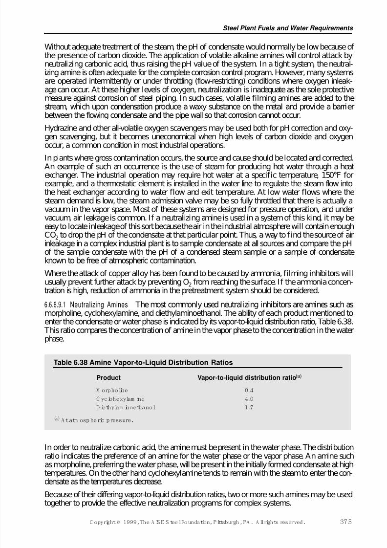
7/17/2019 Steel Plants Fuels and Water Consumption
http://slidepdf.com/reader/full/steel-plants-fuels-and-water-consumption 97/102
Without adequate treatment of the steam, the pH of condensate would normally be low because of the presence of carbon dioxide. The application of volatile alkaline amines will control attack byneutralizing carbonic acid, thus raising the pH value of the system. In a tight system, the neutral-izing amine is often adequate for the complete corrosion control program. However, many systemsare operated intermittently or under throttling (flow-restricting) conditions where oxygen inleak-age can occur. At these higher levels of oxygen, neutralization is inadequate as the sole protective
measure against corrosion of steel piping. In such cases, volatile filming amines are added to thestream, which upon condensation produce a waxy substance on the metal and provide a barrierbetween the flowing condensate and the pipe wall so that corrosion cannot occur.
Hydrazine and other all-volatile oxygen scavengers may be used both for pH correction and oxy-gen scavenging, but it becomes uneconomical when high levels of carbon dioxide and oxygenoccur, a common condition in most industrial operations.
In plants where gross contamination occurs, the source and cause should be located and corrected.An example of such an occurrence is the use of steam for producing hot water through a heatexchanger. The industrial operation may require hot water at a specific temperature, 150°F forexample, and a thermostatic element is installed in the water line to regulate the steam flow into
the heat exchanger according to water flow and exit temperature. At low water flows where thesteam demand is low, the steam admission valve may be so fully throttled that there is actually avacuum in the vapor space. Most of these systems are designed for pressure operation, and undervacuum, air leakage is common. If a neutralizing amine is used in a system of this kind, it may beeasy to locate inleakage of this sort because the air in the industrial atmosphere will contain enoughCO2 to drop the pH of the condensate at that particular point. Thus, a way to find the source of airinleakage in a complex industrial plant is to sample condensate at all sources and compare the pHof the sample condensate with the pH of a condensed steam sample or a sample of condensateknown to be free of atmospheric contamination.
Where the attack of copper alloy has been found to be caused by ammonia, filming inhibitors willusually prevent further attack by preventing O2 from reaching the surface. If the ammonia concen-tration is high, reduction of ammonia in the pretreatment system should be considered.
6.6.6.9.1 Neutralizing Amines The most commonly used neutralizing inhibitors are amines such asmorpholine, cyclohexylamine, and diethylaminoethanol. The ability of each product mentioned toenter the condensate or water phase is indicated by its vapor-to-liquid distribution ratio, Table 6.38. This ratio compares the concentration of amine in the vapor phase to the concentration in the waterphase.
In order to neutralize carbonic acid, the amine must be present in the water phase. The distributionratio indicates the preference of an amine for the water phase or the vapor phase. An amine suchas morpholine, preferring the water phase, will be present in the initially formed condensate at hightemperatures. On the other hand cyclohexylamine tends to remain with the steam to enter the con-
densate as the temperatures decrease.
Because of their differing vapor-to-liquid distribution ratios, two or more such amines may be usedtogether to provide the effective neutralization programs for complex systems.
Table 6.38 Amine Vapor-to-Liquid Distribution Ratios
Product Vapor-to-liquid distribution ratio(a)
M orpholine 0.4
C yclohexylam ine 4.0
D iethylam inoethanol 1.7
(a) A t atm osp heric pressure.
Steel Plant Fuels and Water Requirements
C opyright © 1999, The A IS E S teel Foundation, Pittsburgh, PA . A ll rights reserved. 375

7/17/2019 Steel Plants Fuels and Water Consumption
http://slidepdf.com/reader/full/steel-plants-fuels-and-water-consumption 98/102
Neutralizing amines are fed to the feed water after deaeration, boiler steam drum, or steam header. They are controlled by monitoring the returned condensate pH from samples taken at the begin-ning, middle, and end of a condensate system.
6.6.6.9.2 Filming Inhibitors Inhibitors used to film condensate systems are amines with chain-likemolecules. One end of each molecule is hydrophilic (loves water), and the other end hydrophobic
(hates water). The hydrophilic end attaches to the metal, leaving the other end to repel water. Asthe molecules accumulate, the surface becomes non-wettable. The film, therefore, provides a bar-rier against metal attack by water containing carbon dioxide, oxygen, or ammonia. Because themolecules also repel each other, they do not tend to build up layers or thick films. Instead, theyremain a monomolecular protective film.
A film one molecule thick actually improves heat transfer in condensers, dryers, and other heatexchange equipment. By promoting dropwise condensation, an insulating water film between thewater and metal surface is prevented.
Good distribution of filming inhibitors is of prime importance in preventing condensate corrosion.Protection depends on the maintenance of a continuous film. Because steam and condensate can
wash away the film, it must be constantly repaired by continuous feed of the inhibitor.Octadecylamine and certain of its salts were the first chemicals to be used as filming inhibitors insteam-condensate systems. However, because of their wax-like nature (whether supplied in flakeor emulsion form), it was difficult to put these chemicals into uniform solutions for feeding. A rel-atively narrow condensate pH range of 6.5 to 8.0 is required for the octadecylamine to form a filmand to remain on the metal surface. To overcome these limitations molecules formulated specifi-cally for boiler plant conditions have been developed as alternatives to octadecylamine.
Most filming inhibitors are normally fed to the steam header, but may be fed to the feed water orboiler drum; the latter feed points result in some loss of product to blowdown. If only the processequipment needs protection, the inhibitor may be conveniently fed into the desuperheating water atthe process steam header. Regardless of the feed point, however, the inhibitor should be fed con-tinuously for best results. Dosages are not based on oxygen or carbon dioxide content of the steam. The amount of inhibitor required is set according to the system surface area. Creation of an effec-tive film is a physical process, highly dependent on flow rates, feeding, and testing techniques.
6.6.6.10 Evaluating Result s
There are several good ways of determining how much corrosion is occurring in a system and howeffective a prevention program is. Because this requires extensive monitoring, it is essential thatsampling be done at the significant points of the system and with adequate facilities. There mustbe a quill installed in the line that projects into the flowing stream; a sample taken along the pipewall is meaningless. Sample lines must be of stainless-steel tubing.
6.6.6.10.1 pH Monitoring This involves checking the pH throughout a system, necessary to makesure that: sufficient amine is being fed to neutralize carbon dioxide, the proper amine is used togive total system protection, and process contamination or air inleakage is not occurring.
When taking condensate samples, to avoid carbon dioxide flashing off and giving false results, thesample must be cooled prior to contact with the atmosphere. This means using a sample coolerattached to the condensate line. The sample may be throttled at the outlet but not at the inlet. Thisis done to prevent a vacuum from occurring in the coil and drawing in air, which will give falseresults. Failure to set up a cooler properly will give inaccurate and misleading results.
6.6.6.10.2 Conductivity Monitoring The conductivity of the returning condensate can be an indicatorof process contaminants and corrosion.
6 .6.6.10.3 Carbon Dioxide Testing By actually measuring the carbon dioxide content of the conden-sate, the problem of corrosion from carbon dioxide can be directly monitored.
Ironmaking Volume
376 C opyright © 1999, The A IS E S teel Foundation, Pittsburgh, PA . A ll rights reserved.
7/17/2019 Steel Plants Fuels and Water Consumption
http://slidepdf.com/reader/full/steel-plants-fuels-and-water-consumption 99/102
6.6.6.10.4 Hardness Similar to conductivity measurement, this can be an indicator of process con-taminants, particularly from cooling water leakage.
6.6.6.10.5 Test Nippl es The use of test nipples, installed in steam or condensate lines, permits bothvisual inspection of system conditions and a measure of corrosion.
6.6.6.10.6 Test Coupons These have also been used to evaluate condensate corrosion conditions.Preweighed coupons in holders are inserted into condensate lines. After an arbitrary time interval(usually at least 30 days), the coupons are removed, cleaned, and reweighed. The difference in orig-inal and final weight, when coupon surface area and exposure time are known, gives an indicationof rate of metal loss owing to corrosion. It should be noted, however, that such test coupons usu-ally cannot identify bottom grooving and threaded-joint corrosion as they occur in actual piping.
6.6.6.10.7 Iron and Copper Testing for corrosion products (iron and copper) in condensate is a pre-ferred and widely used means of observing corrosion trends. Because metal corrosion products incondensate are mainly present as insoluble particulates rather than in dissolved form, methods of sampling that insure representative and proportional collection of particulates are important.
A general level of corrosion products in the 0–50g/litre range indicates the system is in control.
Because of the problem of sampling error when looking for this small quantity of particulates, arelatively large amount of sample needs to be run. Two accepted methods used are visual estima-tion and quantitative measurement.
Visual estimation of iron concentration is based on the relative degree of discoloration of a mem-brane filter through which a known volume of condensate is passed. Estimation is made by com-paring the membrane pad, after filtration of the sample, with prepared standard pads having colorequivalents for specific iron values.
Very precise quantitative determinations of total iron and copper values are easily made by theAnalex method. In this procedure, a sample stream of condensate is allowed to flow through asmall plastic cartridge containing a high-purity filter of ion exchange materials for a period of 7 to
30 days. Particulates are captured by filtration, while dissolved solids are retained by ion exchange.By a unique laboratory process, the total weight of each metal is calculated. A series of successiveanalyses gives a complete and accurate picture of condensate corrosion trends. Normally, wheninhibitors are used in a system previously untreated, the corrosion products observed in the con-densate will increase temporarily. Most inhibitors have a detergent effect and tend to slough off oldoxides. This must be taken into consideration when evaluating test results.
Normally a plant uses more than one of the above monitoring methods (e.g. pH monitoring andcorrosion coupons). Although it may seem inconvenient when initially setting up a program tomonitor the condensate, the results are more than worth the time invested in avoiding downtimeand gaining energy savings in the high-heat value and high-purity of the returned condensate.
6.6.6.11 Steam Sampling
The most difficult sampling is of the steam itself as a representative sample is hard to obtain with-out making special provisions for it. The ASTM recommended procedure for sampling steam andcondensing this for analysis should be followed. The analysis may only require a determination of pH to establish the level produced by the application of a neutralizing amine as a benchmark forinterpreting the pH of samples of condensate. On the other hand, steam sampling is extremely valu-able as a means of locating sources of trouble in a system.
Hydrogen analysis of steam will help determine boiler corrosion rate with respect to steaming load.Hydrogen evolution results from active corrosion cells or chemical decomposition. Experienced
consultants should conduct these tests so that correct interpretations can be made. The corrosionaction within the boiler can be easily observed on the hydrogen analyzer chart; destruction of theprotective film of magnetite produces hydrogen directly from the attack of the boiler steel.
Steel Plant Fuels and Water Requirements
C opyright © 1999, The A IS E S teel Foundation, Pittsburgh, PA . A ll rights reserved. 377
7/17/2019 Steel Plants Fuels and Water Consumption
http://slidepdf.com/reader/full/steel-plants-fuels-and-water-consumption 100/102
A common method for determining steam quality is by use of the specific ion electrode for sodium.As the salts dissolved in the boiler water are sodium salts, the presence of sodium in the steam sam-ple is a direct indication of carryover. A trained steam purity consultant should be contracted.
ReferencesGeneral
1. Steel at the Crossroads , (Washington D.C.: American Iron and Steel Institute).2. T. Baumeister, ed.,Marks Standard Handbook for Mechanical Engineers , 8th ed. (New York:
McGraw-Hill, 1978).3. J. S. S. Brame and J. G. King, Fuel—Solid, Liquid and Gaseous (London: Edward Arnold,
1967).4. A. J. Chapman, Heat Transfer , 4th ed. (New York: MacMillan, 1984).5. D. M. Considine, ed., Energy Technology Handbook (New York: McGraw-Hill, 1977).6. R. M. Fristrom and A. A. Westenberg, Flame Structure , (New York: McGraw-Hill, 1965).7. B. Gebhart, Heat Transfer (New York: McGraw-Hill, 1961).8. W. H. Giedt, Principles of Engineering Heat Transfer (New York: Van Nostrand, 1957).9. J. Griswold, Fuels, Combustion and Furnaces (New York: McGraw-Hill, 1946).
10. Hauck Industr ial Combustion Data Handbook , 3rd ed. (Lebanon, PA: Hauck ManufacturingCompany, 1953).
11. R. F. Hill, ed., A Decade of Progress, Energy Technology X , (Government Institutes, Inc.,annual publication, June, 1983).
12. H. C. Hottel and A. F. Sarofim, Radiative Transfer (New York: McGraw-Hill, 1967).13. O. A. Hougen et al., Chemical Process Principles: Part I , 2nd ed. (New York: J ohn Wiley and
Sons, 1954).14. O. A. Hougen et al.,Mater ial and Energy Balances: Part I I, 2nd ed. (New York: John Wiley
and Sons, 1959).15. O. A. Hougen et al., Thermodynamics: Part I I I (New York: J ohn Wiley and Sons, 1947).16. O. A. Hougen et al., Kinetics: Charts , 3rd ed. (New York: John Wiley and Sons, 1964).17. “Waste-Heat Recovery,” in Proceedings of 1961 I nsti tute of Fuel Conference (London:
Chapman and Hall, Ltd., 1963).18. M. J akob, Elements of Heat Transfer , 3rd ed. (New York: John Wiley and Sons, 1957).19. A. J. Johnston and G. H. Auth, Fuels and Combustion Handbook (New York: McGraw-Hill,
1951).20. B. Lewis and R. N. Pease, Combustion Processes (Princeton University Press, 1956).21. B. Lewis and G. von Elbe, Combusti on, Flames and Explosions of Gases (New York:
Academic Press, 1951).
22. G. N. Lewis et al., Thermodynamics , 2nd ed. (New York: McGraw-Hill, 1961).23. C. O. Mackey et al., Engineer ing Thermodynamics (New York: J ohn Wiley and Sons, 1957).24. W. H. McAdams, Heat Transmission , 3rd ed. (New York: McGraw-Hill, 1954).25. Nor th Amer ican Combustion Handbook , 2nd ed. (The North American Manufacturing
Company Company, 1978).26. J. R. O’Loughlin, “Generalized Equations for Furnace Combustion Calculations,”
Combustion 34:5 (1963): 23–4.27. R. H. Perry et al., eds. Chemical Engineers’ Handbook , 6th ed. (New York: McGraw-Hill,
1984).28. A. Schack, Industr ial Heat Transfer , 6th ed. (New York: John Wiley and Sons, 1965) (trans-
lated from German).
29. M. L. Smith and K. W. Stinson, Fuels and Combustion (New York: McGraw-Hill, 1952).30. R. A. Strehlow, Fundamental s of Combusti on (Scranton, PA: International TextbookCompany, 1967).
Ironmaking Volume
378 C opyright © 1999, The A IS E S teel Foundation, Pittsburgh, PA . A ll rights reserved.
7/17/2019 Steel Plants Fuels and Water Consumption
http://slidepdf.com/reader/full/steel-plants-fuels-and-water-consumption 101/102
31. “Temperature—Its Measurement and Control in Science and Industry,”American Institute of Physics 5 (1982).
32. W. Trinks and M. H. Mawhinney, Industr ial Fur naces, Vol. I , 5th ed. (New York: John Wileyand Sons, 1961)
33. W. Trinks and M. H. Mawhinney, Industr ial Furnaces, Vol. I I , 4th ed. (New York: John Wileyand Sons, 1967).
34. U.S. Department of Energy Research, Development and Demonstration for EnergyConservation: Preliminary Identification of Opportunities in Iron and Steelmaking, ArthurD. Little, 1978.
Coal and Coke— Gener al35. F. J . Donnelley and L. T. Barbour, “Delayed Coke—A Valuable Fuel,” Hydrocarbon
Processing 45:11 (1966): 221–4.36. M. A. Elliot, ed.,Chemistry of Coal Uti l ization , 2nd Supplementary Volume (New York: J ohn
Wiley and Sons, 1981).37. R. A. Glenn and H. J. Rose, The Metallurgi cal, Chemical and Other Process Uses of Coal ,
(Pittsburgh: Bituminous Coal Research, Inc., 1958).38. R. E. Machin,Science in a Coalf ield , 2nd ed. (New York: Pitman, 1952).39. J. W. Leonard, ed., Coal Preparation , 4th ed. (New York: American Institute of Mining,
Metallurgical and Petroleum Engineers, 1979).40. A. Raistrick and C. E. Marshall, Nature and Ori gin of Coal and Coal Seams , (New York:
British Book Centre, 1952).41. D. W. Van Krevelen,Coal (New York: Elsevier, 1961).42. D. W. Van Krevelen and J. Schuyer,Coal Science (New York: Elsevier, 1957).43. P. J. Wilson and J. H. Wells, Coal, Coke and Coal Chemicals (New York: McGraw-Hill,
1950).
Coal and Coke— Test ing44. ASTM Standards, Volume 06.05, Gaseous Fuels, Coal and Coke (Philadelphia: American
Society for Testing and Materials, 1983).45. O. W. Rees, Chemistr y, Uses and Limitati ons of Coal Analyses (Illinois State GeologicalSurvey, R. I. 220, 1966).
46. Bulletin 638, Methods of Analyzing and Testing Coal and Coke (Washington, D.C.: U.S.Bureau of Mines, 1967).
Coal Petrography47. R. J. Gray et al., “Distribution and Forms of Sulfur in a High-Volatile Pittsburgh Seam Coal,”
Transactions, American Institute of Mi ning, Metal lurgi cal and Petrol eum Engineers , Vol.226 (1963): 113–21.
48. J. A. Harrison, “Coal Petrography Applied to Coking Problems,” Proceedings, I l l inois Mining Institute (1961): 17–43.
49. J. A. Harrison, “Application of Coal Petrography to Coal Preparation,” Transactions of SME 226 (1963): 346–57.
50. N. Kaye, “The Application of Coal Petrography in the Production of Metallurgical Coke,”The Coke Oven Manager ’s Yearbook (London: The Coke Oven Managers’ Association,1967).
51. M. Th. Mackowsky, “Practical Possibilities of Coal Petrography,” Compterendu 31e Congress Intern. de Chemie Indust., (Liege, Sept. 1958), Special Libraries Association trans-lation 59-17595.
52. C. E. Marshall, Coal Petrol ogy , Economic Geology, 50th Anniversary Volume, 1955.53. D. M. Mason and F. C. Schora, J r., “Coal and Char Transformation in Hydgrogasification,”
Fuel Gasifi cation, Advances in Chemistry Ser ies No. 69 , American Chemical Society, 1967,
18–30.54. B. C. Parks and H. J. O’Donnell, Petrography of American Coals , (Washington, D.C.: U.S.Bureau of Mines Bulletin 550, 1957).
Steel Plant Fuels and Water Requirements
C opyright © 1999, The A IS E S teel Foundation, Pittsburgh, PA . A ll rights reserved. 379
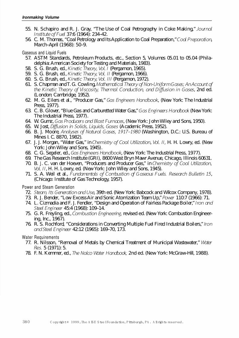
7/17/2019 Steel Plants Fuels and Water Consumption
http://slidepdf.com/reader/full/steel-plants-fuels-and-water-consumption 102/102
55. N. Schapiro and R. J. Gray, “The Use of Coal Petrography in Coke Making,” Journal Insti tute of Fuel 37:6 (1964): 234–42.
56. C. M. Thomas, “Coal Petrology and Its Application to Coal Preparation,”Coal Preparation ,March–April (1968): 50–9.
Gaseous and Liquid Fuels
57. ASTM Standards, Petroleum Products, etc., Section 5, Volumes 05.01 to 05.04 (Phila-delphia: American Society for Testing and Materials, 1983).58. S. G. Brush, ed., Ki netic Theory, Vol. I (Pergamon, 1965).59. S. G. Brush, ed., Ki netic Theory, Vol. I I (Pergamon, 1966).60. S. G. Brush, ed., Kinetic Theory, Vol. II I (Pergamon, 1972).61. S. Chapman and T. G. Cowling,Mathematical Theory of Non-Uniform Gases; An Account of
the Kineti c Theory of Viscosi ty, Thermal Conducti on, and Di ffusion in Gases , 2nd ed.(London: Cambridge, 1952).
62. M. G. Eilers et al., “Producer Gas,” Gas Engineers Handbook , (New York: The IndustrialPress, 1977).
63. C. B. Glover, “Blue Gas and Carburetted Water Gas,”Gas Engineers Handbook (New York:
The Industrial Press, 1977).64. W. Gumz,Gas Producers and Blast Furnaces , (New York: J ohn Wiley and Sons, 1950).65. W. Jost, Diffusion in Solids, Liquids, Gases (Academic Press, 1952).66. B. J. Moore, Analyses of Natural Gases, 1917–1980 (Washington, D.C.: U.S. Bureau of
Mines I. C. 8870, 1982).67. J. J. Morgan, “Water Gas,” inChemistry of Coal Uti li zation , Vol. I I , H. H. Lowry, ed. (New
York: John Wiley and Sons, 1945).68. C. G. Segeler, ed.,Gas Engineers Handbook , (New York: The Industrial Press, 1977).69. The Gas Research Institute (GRI), 8600 West Bryn Mawr Avenue, Chicago, Illinois 60631.70. B. J. C. van der Hoeven, “Producers and Producer Gas,” inChemistry of Coal Uti li zation,
Vol. I I , H. H. Lowry, ed. (New York: John Wiley and Sons, 1945).71. S. A. Weil et al., Fundamental s of Combustion of Gaseous Fuels. Research Bulletin 15 ,
(Chicago: Institute of Gas Technology, 1957).
Power and Steam Generation72. Steam, I ts Generation and Use , 39th ed. (New York: Babcock and Wilcox Company, 1978).73. R. J. Bender, “Low Excess Air and Sonic Atomization Team Up,” Power 110:7 (1966): 71.74. L. Cizmadia and F. J. Fendler, “Design and Operation of Fairless Package Boiler,” I ron and
Steel Engineer 45:4 (1968): 109–14.75. G. R. Freyling, ed.,Combustion Engineer ing, revised ed. (New York: Combustion Engineer-
ing, Inc., 1967).76. R. S. Rochford, “Considerations in Converting Multiple Fuel Fired Industrial Boilers,” Iron
and Steel Engineer 42:12 (1965): 169 70 173
Ironmaking Volume