Embed Size (px)
Citation preview
Procedia Engineering 40 ( 2012 ) 381 – 386
1877-7058 © 2012 Published by Elsevier Ltd.doi: 10.1016/j.proeng.2012.07.112
Steel Structures and Bridges 2012
Steel reinforced ducts stressed by temperature R. Poštaa* and J. Dolejša
a CTU in Prague, Faculty of Civil Engineering, Department of Steel and Timber Structures, Thákurova 7, 166 29 Praha 6, Czech Republic
Abstract
Steel pipelines are an important part of industrial operations in many sectors. Pipelines serve to transport media in liquid and gaseous state. Ducts, with a ratio of pipe diameter to wall thickness up to 150 are considered as simple beams. Ducts with higher ratio are considered as shell elements. In literature we can find how to calculate these structures stressed by many kinds of load. Failures, that have occurred in recent past suggest, that the issue of industrial piping design is not yet fully explored.
The phenomenon presented in this study is behaviour of reinforced steel shell stressed by temperature changes. Due to
high temperature load, there is a big temperature deformation of the whole system. However, the deformation caused by temperature is not the same in all parts of the system. As the high temperature source is inside the pipe, the highest temperature is on the inner surface of the shell. The variation of the temperature in the shell and partial warming of ring stiffeners is caused by heat conduction. Due to the different temperatures of the surrounding environment, the stiffener is warmed less than the shell. Therefore the shell and the stiffener are deformed in a different way. The research is, in more details, focused on the area close to the ring stiffener, where it is a higher possibility of cracks initiation and their expansion due to the cyclical stress. The aim of this study is a construction life diagnosis considering this detail; eventually a proposal of a more effective construction detail. © 2012 Published by Elsevier Ltd. Selection and review under responsibility of University of Žilina, FCE, Slovakia.
Keywords: shell, stiffener, stress, reinforced, temperature, steel, pipe
1. Introduction
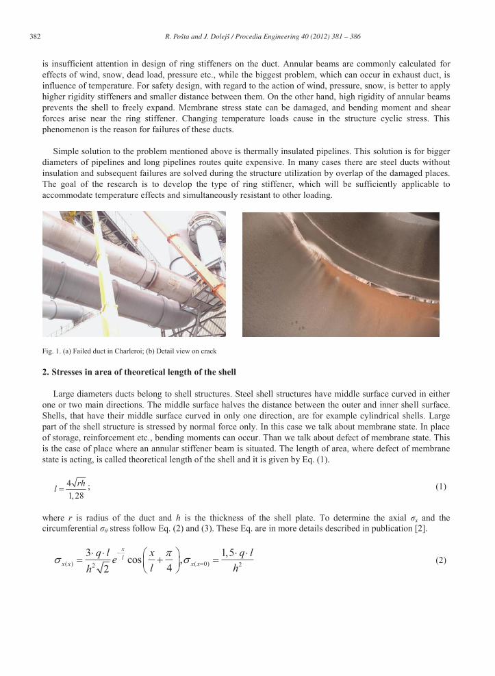
The reason for starting this research have been several accidents, they occurred on steel ducts of industrial structures. For example: failure of exhausting duct in an emission control system at a plant in Washington State [1] or failure of exhausting duct in Belgium town Charleroi (shown in the Fig. 1). The reason of those accidents
* Tel.: +420 224 353 745; fax: +420 233 337 466 Email address: [email protected]
Available online at www.sciencedirect.com
Open access under CC BY-NC-ND license.
Open access under CC BY-NC-ND license.
382 R. Pošta and J. Dolejš / Procedia Engineering 40 ( 2012 ) 381 – 386
is insufficient attention in design of ring stiffeners on the duct. Annular beams are commonly calculated for effects of wind, snow, dead load, pressure etc., while the biggest problem, which can occur in exhaust duct, is influence of temperature. For safety design, with regard to the action of wind, pressure, snow, is better to apply higher rigidity stiffeners and smaller distance between them. On the other hand, high rigidity of annular beams prevents the shell to freely expand. Membrane stress state can be damaged, and bending moment and shear forces arise near the ring stiffener. Changing temperature loads cause in the structure cyclic stress. This phenomenon is the reason for failures of these ducts.
Simple solution to the problem mentioned above is thermally insulated pipelines. This solution is for bigger
diameters of pipelines and long pipelines routes quite expensive. In many cases there are steel ducts without insulation and subsequent failures are solved during the structure utilization by overlap of the damaged places. The goal of the research is to develop the type of ring stiffener, which will be sufficiently applicable to accommodate temperature effects and simultaneously resistant to other loading.
Fig. 1. (a) Failed duct in Charleroi; (b) Detail view on crack
2. Stresses in area of theoretical length of the shell
Large diameters ducts belong to shell structures. Steel shell structures have middle surface curved in either one or two main directions. The middle surface halves the distance between the outer and inner shell surface. Shells, that have their middle surface curved in only one direction, are for example cylindrical shells. Large part of the shell structure is stressed by normal force only. In this case we talk about membrane state. In place of storage, reinforcement etc., bending moments can occur. Than we talk about defect of membrane state. This is the case of place where an annular stiffener beam is situated. The length of area, where defect of membrane state is acting, is called theoretical length of the shell and it is given by Eq. (1).
41,28
rhl ; (1)
where r is radius of the duct and h is the thickness of the shell plate. To determine the axial σx and the circumferential σθ stress follow Eq. (2) and (3). These Eq. are in more details described in publication [2].
( ) ( 0) 22
3 1,5cos ,42
xl
x x x xq l x q le
l hh (2)

383 R. Pošta and J. Dolejš / Procedia Engineering 40 ( 2012 ) 381 – 386
( ) ( 0)sin ,4 22
xl
x xq r x q re
l l hl h (3)
where l is theoretical length of the shell (1) and q is the line load at the perimeter of the shell. The values, given by equations mentioned above, reach high order values. Reason is that those expressions are resultants of simplifying presumptions. In those equations are not considered temperature change through cross section of the stiffener and elasticity of material. For finding the more proper behaviour of this construction detail it is necessary to use finite element method.
3. Finite element modelling
For finite element study authors chose a computer software ANSYS. The example of thermal stressed reinforced duct consists of two parts. In the first part of the calculation is carried out a calculation of thermal changes. They serve as input loads for the second step, which calculates mechanical changes. The first part of the study is called thermal analysis and the second structural analysis. Types of elements, stress-strain diagrams, calculations methods etc. and development of resulting stresses are described in [3]. Results of finite element analysis of typical T stiffeners are shown in Fig. 2.
Fig. 2. (a) Temperature field on structure; (b) Deformation caused by temperature
4. Experiments
To verify numerical modelling (boundary conditions of thermal loading) experiments were performed on existing structure. The objective of this experiment was to monitor temperature changes in the structure depending on the temperature of the flowing medium. Measurement was made on part of dedusting system of the mill in the town of Emmenbrücke in Suisse. Measurement was carried out continuously for six days in August 2011.
To measure the temperature eight thermocouples were used. Pipe diameter and thickness ratio was 1400/5
and stiffener was made of a single plate with dimensions 80/10 mm. The whole part, on which measurement was carried out, is made from stainless steel type X6CrNiMoTi 17-12-2. Location of thermocouples on shell and stiffener is shown on Fig. 3a. The values of measurements were recorded continuously each four seconds. The resulting data shows evaluation of temperature versus time. Measurement data from the fifth day, when operation of mill was switched off, is illustrated in Fig. 3b. The load input for evaluation of measuring was a temperature of the flowing gas, which was measured continuously as well. Two positions in circumferential direction were measured. On both positions thermocouples were located.

384 R. Pošta and J. Dolejš / Procedia Engineering 40 ( 2012 ) 381 – 386
Fig. 3. (a) Location of thermocouples; (b) Temperature evaluation on the structure
4.1. Analytical verification of measured data
Analytical solution is represented by physical transfer and conduction of heat. The result of this task is a temperature of shell and stiffener dependence on temperature of flowing gas. In case of shell it is typical stationary heat conduction in cylindrical wall. Solution of heat transfer between inner environment, wall and outer environment is described in [4]. In case of thin steel plate, it can be considered both surfaces of the shell with almost the same temperature. Then the heat transfer equations are reduced to one, which is described by the following:
1 1 2 2f s s ft t t t (4)
where ts is temperature of the shell, tf1 is temperature of inner environment, tf2 is temperature of outer environment, α1 is the heat transfer coefficient on the inner surface and α2 the heat transfer coefficient on the outer surface. Temperature of flowing gas is known, temperature of outer environment was considered as referent temperature 22°C. Coefficients of heat transfer will be calculated based on heat transfer theory. Convection and radiation are present on both surfaces. On the inner surface, where hot gas is flowing, it is a forced convection and on the outer surface it is the unforced convection. Final value of heat transfer is a summation of both influences. For determination of value of the inner surface heat transfer coefficient is necessary to know the type of flow in the duct. Two types of flow (laminar and turbulent) depend on Reynolds number. For duct with bigger diameters Reynolds number is bigger than 10 000, it means, that these ducts progress a turbulent flow. The relations for calculation of the heat transfer coefficient are published in [5]. Since both coefficients of heat transfer are depending on temperature of the shell, which the sought, eq. (4) was solved by computer software MS excel. Resulting temperature of the shell depending on temperature of flowing gas is shown in Fig. 4a.
In case of stiffener, where authors investigated development of temperature through the cross section of the stiffener, there are used differential equations of heat transfer. These equations were solved by Bessel function. Calculation procedure of stiffened rib by Bessel functions is described in [6]. Resulting temperature in the end of ring stiffener depending on gas flow temperature is shown in Fig. 4b.
385 R. Pošta and J. Dolejš / Procedia Engineering 40 ( 2012 ) 381 – 386
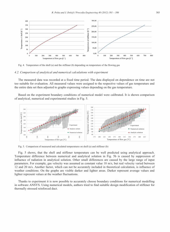
Fig. 4. Temperature of the shell (a) and the stiffener (b) depending on temperature of the flowing gas
4.2. Comparison of analytical and numerical calculations with experiment
The measured data was recorded at a fixed time period. The data displayed on dependence on time are not too suitable for evaluation. All measured values were assigned to the respective values of gas temperature and the entire data set then adjusted to graphs expressing values depending on the gas temperature.
Based on the experiment boundary conditions of numerical model were calibrated. It is shown comparison
of analytical, numerical and experimental studies in Fig. 5.
100
120
140
160
180
200
220
240
180
230
280
330
380
430
Temperature of flow gas [°C]
Tem
pera
ture
of t
he sh
ell [ °
C]
Experiment
Analytic solutin
Numerical solution
80
90
100
110
120
130
140
150
160
170
180
175 200 225 250 275 300 325 350 375 400 425
Temperature of flow gas [°C]
Tem
pera
ture
of s
tiffe
ner [°C
]
Experiment
Numerical solution
Analytic solution
Fig. 5. Comparison of measured and calculated temperatures on shell (a) and stiffener (b) Fig. 5 shows, that the shell and stiffener temperature can be well predicted using analytical approach.
Temperature difference between numerical and analytical solution in Fig. 5b is caused by suppression of influence of radiation in analytical solution. Other small differences are caused by the large range of input parameters. For example, gas velocity was assumed as constant value 18 m/s, but real velocity varied between 12 and 20 m/s. Another factor, which can not be accurately included in theoretical calculation, is influence of weather conditions. On the graphs are visible darker and lighter areas. Darker represent average values and lighter represent values at the weather fluctuations.
Thanks to experiment it is now possible to accurately choose boundary conditions for numerical modelling
in software ANSYS. Using numerical models, authors tried to find suitable design modification of stiffener for thermally stressed reinforced duct.

386 R. Pošta and J. Dolejš / Procedia Engineering 40 ( 2012 ) 381 – 386
5. Conclusion
Numerical calculations demonstrate, that more rigid stiffeners (T, I stiffeners), which have necessary influence on load bearing and buckling stability of duct, have unfavourable properties with respect to thermal stress of structure. It is caused by insufficient heating of an external part (flange of stiffeners Fig. 2a) of the stiffener. Goal of the study is to create the stiffener of the duct, which will not cause large thermal effect and simultaneously will be resistant enough. One way, that seems to be possible, is a connection of annular beam with warm duct shown in Fig. 6. Stiffness of a single annular flange increase by greater co-operating area of shell and whole part of additional structure will heat up more uniformly. This reinforcement type of thermally stressed duct will be further tested on influence of other kinds of loads and buckling stability of the duct. In Fig. 6 is shown deformation (a-temperature, b-underpressure) of the duct with reinforcement mentioned above. In these figures can be seen similar resistance of the classic stiffener rib and reinforcement with transverse plates stressed by underpressure and bigger deformation capacity of new type of reinforcement with temperature acting.
Fig. 6. Deformations of the duct stressed by temperature (a) and underpressure (b)
Acknowledgements
This research is supported by student grant SGS12/033/OHK1/1T/11
References
[1] O´Donnell W.J., Watson J.M., Mallin W.B., Kenrick J.R.: Low cycle thermal fatigue and fracture of reinforced piping, Analyzing Failures: The problem and the solutions, Salt Lake City, Utah, USA, 2-6 December 1985, pp. 227-236
[2] Beitz W., Kuttner K., Zhang W.: Dubbel – Handbook of Mechanical engineering, Springer-Verlag, London, 1994 [3] Pošta R., Dolejš J.: Stiffened steel cylindrical shells at elevated temperature, Proccedings of 6th European Conference on steel and
Composite Structures, Budapest, 2011, p.867-872 [4] Yunus A. Cengel: Heat transfer A Practical approach, McGraw-Hill, USA, 1998 [5] Jurečka P., Proudění a sdílení tepla, Ostrava, 2006, ISBN 80-248-1083-2 [6] Filková I., Tepelné pochody: Příklady výpočtů 2, Praha, 1983