Embed Size (px)
Citation preview

1
V 1.0 – Rev. 09.10.07
AASHTO- Load and Resistance Factor Design (LRFD)
Steel Structures
Mahir Sen, P.E. and Paul Pilarski, P.E.
Credits
The content for this course has been provided by the following PB employees:
Narrated by Greg Metzger, PB University

2
• For your convenience and future reference, you may download a PDF version of this course.
• Click on the ATTACHMENTS link located in the upper right corner of this course window to access the document and save the file to your desktop.
Download Information
Course Navigation

3
Throughout the course review questions are provided. These are designed to reinforce what you have learned in this course and help prepare you for the final assessment. The review scores will not count toward your final grade on the assessment.
Reinforcement
• After completing the content within the course you will be asked to take a final test to ensure that you mastered the key training objectives.
• You will need to make a minimum scoreof 80% on the final assessment to receive credit for passing the course.
• Successful completion of the course will earn 0.1 IACET CEU.
• Please refer to your state’s specific continuing education requirements regarding applicability.
Successful Completion
4
This class is the fourth class in the Structures TRC curriculum for LRFD Design, developed internally at PB. The curriculum focuses on the following ten areas of major change introduced bythe LRFD Bridge Design Specifications:
• Foundations
• Decks & Deck Systems
• Joints and Bearings
• Abutments, Piers, and Walls
• Railings
• Introduction to LRFD
• Loads and Load Factors
• Concrete Structures
• Steel Structures
• Buried Structures
LRFD Design Curriculum
After successfully completing the course you will be able to identify:
• The three areas where the LRFD code changes past practice of steel structures design
• The basic proportioning of economic steel structures
• Applications of the LRFD design philosophy to basic steel structures
• The checks required in steel girder design
• The resources and alternate examples available to designers
The class will take you approximately one hour to complete.
Objectives

5
• Present rules of thumb for economic construction and selection of steel plates
• Provide guidance on analysis procedures
• Walk through the basic implementation of LRFD
• Demonstrate checks required by the LRFD Specifications as applied to a simple span steel girder
• Present and explain an example problem
• Identify resources and alternate examples available to designers
The LRFD Steel Structures section covers a wide variety of applications. This course will give guidance on some basic principles in steel design and demonstrate LRFD by focusing on one of the most basic applications – a simple span composite steel girder bridge. The course will:
Course Description
1. LRFD Changes from Prior Specifications
2. Analysis Options
3. Proportioning Recommendations
4. Checks Required by the LRFD Specifications
5. LRFD Design of Simple Span Steel Girder
6. Resources
Course Outline
Course Outline- LRFD Steel Structures

6
Topic 1
LRFD Changes from Prior Specifications
Topic 1
LRFD Changes
• LRFD has removed 25 ft. max. diaphragm spacing requirement
• Live Load deflection check is optional and per owner preference
• LRFD produces lower Live Load stress range
• LRFD requires higher number of load cycles
1. LRFD Changes from Prior Specifications

7
LRFD Changes, cont.
• Simplified Fatigue Design Provisions
• LRFD is more reflective of actual conditions
• Unified Specs for Straight and Curved Steel Girders
• Parallel Commentary
1. LRFD Changes from Prior Specifications
8
Review
Question Review
LL deflection check is optional
LRFD is more reflective of actual conditions
Shear design has been simplified
Maximum diaphragm spacing of 25 feet has been removed
The correct option to the question on the last slide is: Shear design has been simplified. Unfortunately, shear design has not been simplified. The other items listed have been implemented in LRFD.
Which of the following is not a change implemented in LRFD?
Course Outline
1. LRFD Changes from Prior Specifications
2. Analysis Options
3. Proportioning Recommendations
4. Checks Required by the LRFD Specifications
5. LRFD Design of Simple Span Steel Girder
6. Resources
Course Outline- LRFD Steel Structures

9
Topic 2
Analysis Options
Topic 2
• Model using beam + deck as composite section throughout length
• Larger negative & smaller positive moments
• Model using beam + deck reinforcement as composite section in negative moment region
• Larger positive & smaller negative moments
• LRFD 4.5.2.2 & commentary allow top model to be used.
2. Analysis Options
Analysis Options
10
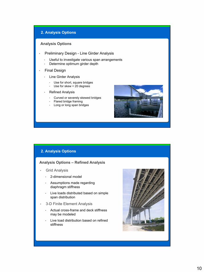
• Preliminary Design - Line Girder Analysis• Useful to investigate various span arrangements• Determine optimum girder depth
• Final Design• Line Girder Analysis
• Use for short, square bridges• Use for skew < 20 degrees
• Refined Analysis• Curved or severely skewed bridges• Flared bridge framing• Long or long span bridges
2. Analysis Options
Analysis Options
• Grid Analysis• 2-dimensional model
• Assumptions made regarding diaphragm stiffness
• Live loads distributed based on simple span distribution
• 3-D Finite Element Analysis• Actual cross-frame and deck stiffness
may be modeled
• Live load distribution based on refined stiffness
2. Analysis Options
Analysis Options – Refined Analysis

11
1. LRFD Changes from prior Specifications
2. Analysis Options
3. Proportioning Recommendations
4. Checks Required by the LRFD Specifications
5. LRFD Design of Simple Span Steel Bridge
6. Resources
Course Outline
Course Outline- LRFD Steel Structures
Topic 3
Proportioning Recommendations
Topic 3

12
• Minimum depths shown in AASHTO are often not the most economical (LRFD Table 2.5.2.6.3-1.)
• Use as wide a girder spacing as practical. Staged re-decking requirements may control girder spacing
• Some states limit fascia girder to 1 ft from gutterline for rolled beams and 2 ft from gutterline for plate girders. This is to accommodate contractor forms
• Limit field section lengths to 120 ft for shipping and erection
• Both flanges should meet NSBA rule of thumb for shipping and handling: bf > L/85
3. Proportioning Recommendations
Recommendations
• Use constant width bottom flange for straight girders
• Use constant width top flange between field splices
• Economical to change flange section at field splices and where a minimum of 800 lbs of steel can be saved
• Locate bolted splices as near inflection points as possible
• Set –M region diaphragm spacing based on bottom flange under all loads
• Set +M region diaphragm spacing based on top flange under construction loads on non-composite beam section
3. Proportioning Recommendations
Recommendations, cont.

13
• Size stiffener widths in even inches – allows the use of bar stock
• Avoid longitudinal stiffeners
• Use 7/16” minimum web thickness to control welding distortions
• Use 3/4” minimum flange thickness
3. Proportioning Recommendations
Recommendations, cont.

14
Review
Question Review
Use a web thickness greater than 7/16”
Use 3/4” minimum compression flange thickness
Use a constant width bottom flange
Keep flange widths smaller than the shipping length/85
Which of the following is NOT a recommendation for an economical structure?
The option Keep flange widths smaller than the shipping length/85 is incorrect. The flange width should be kept greater than L/85. All of the other options are recommendations for economical steel I-girders.
1. LRFD Changes from prior Specifications
2. Analysis Options
3. Proportioning Recommendations
4. Checks Required by the LRFD Specifications
5. LRFD Design of Simple Span Steel Girder
6. Resources
Course Outline
Course Outline- LRFD Steel Structures

15
Topic 4
Checks Required by the LRFD Specifications
Topic 4
4. Checks Required by the LRFD Specifications
LRFD Checks
A. Service Limit State Checks for• Elastic Deformations• Permanent Deformations
B. Constructability Checks for• Flexure• Shear
C. Fatigue and Fracture State Check for• Fatigue• Fracture• Special Fatigue Requirements for Web

16
4. Checks Required by the LRFD Specifications
D. Strength Limit State Check for
• Flexure• Compact or Non-compact Section• Ductility Requirement
• Shear• Check whether Web Stiffeners are required• Transverse Stiffener Design• Flange-to-Web Welds• Bearing Stiffeners• Shear Connectors for Composite Sections
1. LRFD Changes from prior Specifications
2. Analysis Options
3. Proportioning Recommendations
4. Checks Required by the LRFD Specifications
5. LRFD Design Example - Simple Span Steel Girder
6. Resources
LRFD Steel Structures
Course Outline

17
Topic 5
LRFD Design Example - Simple Span Steel Girder
Topic 5
5. LRFD Design Example - Simple Span Steel Girder
Framing Plan: 100’-0” Long Simple Span
Preliminary Design Steps
1. Choose girder spacing and preliminary diaphragm spacing
Stringer (Typ.)
Diaphragm (Typ.)
4 Spa. @ 25’-0”
3 @
8’-4
”= 2
5’-0
”

18
5. LRFD Design Example - Simple Span Steel Girder
Framing Plan: 100’-0” Long Simple Span
Typical Section
2. Choose preliminary sizes for web and flange plates
3. Determine deck thickness requirements for selected configuration
4. Analyze to determine moments and shears
5. Check section proportion limits per LRFD 6.10.2
Refer also to LRFD Chapter 6, Appendix C for basic steps and code references
Preliminary Design Steps
5. LRFD Design Example - Simple Span Steel Girder

19
5. LRFD Design Example - Simple Span Steel Girder
Trial Section
20”
PLASTIC NEUTRAL AXISOF PLATE GIRDER
ELASTIC NEUTRAL AXISOF PLATE GIRDER
23.3
3”38
.92”
60”
51.3
2”10
.93”
3 / 4”
7/16”
16”
11/ 2”
5. LRFD Design Example - Simple Span Steel Girder
Check web proportions per LRFD 6.10.2 (Webs without longitudinal stiffeners in (+) flexure):
D / tw ≤ 150 Art. 6.10.2.1.1-1
where D is depth of the web between flanges, in
tw is web thickness, in
60 / (7/16) = 137 < 150 OK

20
5. LRFD Design Example - Simple Span Steel Girder
Flexural Components will be proportioned such that:
0.11.0 ≤≤yt
yc
II
where Iyc = moment of inertia of the compression flange about the vertical axis, in4
Iyt = moment of inertia of the tension flange about the vertical axis, in4
Iyc = (3/4) 163 / 12 = 256 in4
Iyt = (11/2) 203 / 12 = 1000 in4
0.1 < Iyc / Iyt = 256/1000 = 0.26 < 1.0 OK
Compression Flange:bf / 2tf ≤ 12.0 16 / (2 x 0.75) = 10.7 < 12.0 OK
Tension Flange:bf ≥ D/6 16 > 60/6 = 10 OK
tf ≥ 1.1tw 0.75 > 1.1 (7/16) = 0.48 OK
21
Review
Question Review
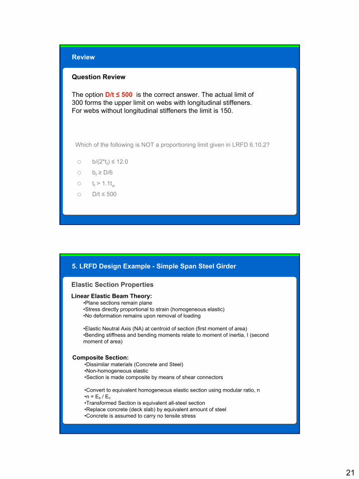
b/(2*tf) ≤ 12.0
bf ≥ D/6
tf > 1.1twD/t ≤ 500
Which of the following is NOT a proportioning limit given in LRFD 6.10.2?
The option D/t ≤ 500 is the correct answer. The actual limit of 300 forms the upper limit on webs with longitudinal stiffeners. For webs without longitudinal stiffeners the limit is 150.
5. LRFD Design Example - Simple Span Steel Girder
Elastic Section PropertiesLinear Elastic Beam Theory:
•Plane sections remain plane•Stress directly proportional to strain (homogeneous elastic)•No deformation remains upon removal of loading
•Elastic Neutral Axis (NA) at centroid of section (first moment of area)•Bending stiffness and bending moments relate to moment of inertia, I (second moment of area)
Composite Section:•Dissimilar materials (Concrete and Steel)•Non-homogeneous elastic•Section is made composite by means of shear connectors
•Convert to equivalent homogeneous elastic section using modular ratio, n•n = Es / Ec•Transformed Section is equivalent all-steel section•Replace concrete (deck slab) by equivalent amount of steel•Concrete is assumed to carry no tensile stress

22
Computation of Elastic Section Properties (Steel girder alone)
Material A d Ad Ad 2 Io I
Top Flange 16 x ¾ 12.0 30.38 365 11,090 11,090
Web 7/16 x 60 26.3 7,880 7,880
Bottom Flange 20 x 1 ½ 30.0 -30.75 -923 28,370 28,370
68.3 -558 47,340
ds = -558/68.3 = 8.17 in. -8.17 x 558 = -4,560
INA = 42,780
Distance from neutral axis of steel section to:
Top of steel = 30 + 0.75 + 8.17 = 38.92 in.
Bottom of steel = 30 + 1.50 – 8.17 = 23.33 in.
Section modulus, top of steel
Sst = 42,780 / 38.92
= 1,100 in3
Section modulus, bottom of steel
Ssb = 42,780 / 23.33
= 1,830 in3
5. LRFD Design Example - Simple Span Steel Girder
Computation of Elastic Section Properties (Composite Section)
243n
rounded 0.86.7ksi 3834ksi 000,29
ksi 3834ksi 4)kcf 150.0(000,33000,33 5.1'5.1
=
⇒===
=××=××=
c
ccc
EEn
fwE Eqn. 5.4.2.4-1
Eqn. 6.10.1.1.1b-1
See Comm. C6.10.1.1.1d
Use 3n = 24 for long-term dead loads such as sidewalks, parapets, future overlay, utilities
Use n = 8 for short-term loads such as live loads
5. LRFD Design Example - Simple Span Steel Girder

23
Computation of Elastic Section Properties (Composite, 3n = 24)
Material A d Ad Ad 2 Io I
Steel Section 68.3 -558 47,340
Concrete 100 x 8 ½ / 24 35.4 37.00 1,310 48,470 210 48,680
103.7 752 96,020
ds = 752/103.7 = 7.25 in. -7.25 x 752 = -5,450
INA = 90,570
Distance from neutral axis of steel section to:
Top of steel = 30.75 - 7.25 = 23.50 in.
Bottom of steel = 31.50 + 7.25 = 38.75 in.
Top of Concrete = 23.50 + 2.00 + 8.50 = 34.00 in.
Top of steel
Sst = 90,570 / 23.50
= 3,850 in3
Bottom of steel
Ssb = 90,570 / 38.75
= 2,340 in3
Section modulus
Top of Concrete
Sc = 90,570 / 34.00
= 2,660 in3
5. LRFD Design Example - Simple Span Steel Girder
Computation of Elastic Section Properties (Composite, n = 8)
Material A d Ad Ad 2 Io I
Steel Section 68.3 -558 47,340
Concrete 100 x 8 ½ / 8 106.3 37.00 3,933 145,520 640 146,160
174.6 3,375 193,500
ds = -3,375/174.6 = 19.33 in. -19.33 x 3,375= -65,240
INA = 128,260
Distance from neutral axis of steel section to:
Top of steel = 30.75 – 19.33 = 11.42 in.
Bottom of steel = 31.50 + 19.33 = 50.83 in.
Top of Concrete = 11.42 + 2.00 + 8.50 = 21.92 in.
Top of steel
Sst = 128,260 / 11.42
= 11,230 in3
Bottom of steel
Ssb = 128,260 / 50.83
= 2,520 in3
Section modulus
Top of Concrete
Sc = 128,260 / 21.92
= 5,850 in3
5. LRFD Design Example - Simple Span Steel Girder

24
Review
Question Review
Creep in the steel will create higher stresses in the concrete due to permanent loads
Shear connectors must be designed assuming increased stresses at the flange interface
Creep in the concrete will create higher stresses in the steel due to permanent loads
Reduced section properties are required to accurately compute LL deflection
Why must one compute section properties for a modulus ratio of 3n?
The correct option is Creep in the concrete will create higher stresses in the steel due to permanent loads. Concrete creep redistributes stresses to stiffer steel sections; using 3 times the modulus ratio is an approximate way to account for this.
25
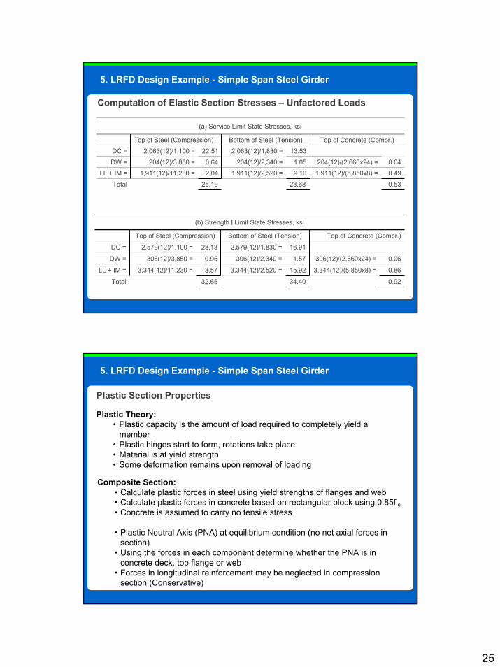
Computation of Elastic Section Stresses – Unfactored Loads
(a) Service Limit State Stresses, ksi
Top of Steel (Compression) Bottom of Steel (Tension) Top of Concrete (Compr.)
DC = 2,063(12)/1,100 = 22.51 2,063(12)/1,830 = 13.53
DW = 204(12)/3,850 = 0.64 204(12)/2,340 = 1.05 204(12)/(2,660x24) = 0.04
LL + IM = 1,911(12)/11,230 = 2.04 1,911(12)/2,520 = 9.10 1,911(12)/(5,850x8) = 0.49
Total 25.19 23.68 0.53
0.9234.4032.65Total
0.863,344(12)/(5,850x8) =15.923,344(12)/2,520 =3.573,344(12)/11,230 =LL + IM =
0.06306(12)/(2,660x24) =1.57306(12)/2,340 =0.95306(12)/3,850 =DW =
16.912,579(12)/1,830 =28.132,579(12)/1,100 =DC =
Top of Concrete (Compr.)Bottom of Steel (Tension)Top of Steel (Compression)
(b) Strength I Limit State Stresses, ksi
5. LRFD Design Example - Simple Span Steel Girder
Plastic Section Properties
Plastic Theory:• Plastic capacity is the amount of load required to completely yield a
member• Plastic hinges start to form, rotations take place• Material is at yield strength• Some deformation remains upon removal of loading
Composite Section:• Calculate plastic forces in steel using yield strengths of flanges and web• Calculate plastic forces in concrete based on rectangular block using 0.85f’c• Concrete is assumed to carry no tensile stress
• Plastic Neutral Axis (PNA) at equilibrium condition (no net axial forces in section)
• Using the forces in each component determine whether the PNA is in concrete deck, top flange or web
• Forces in longitudinal reinforcement may be neglected in compression section (Conservative)
5. LRFD Design Example - Simple Span Steel Girder
26
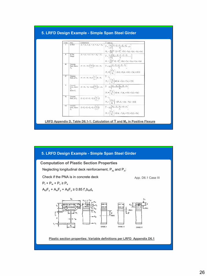
LRFD Appendix D, Table D6.1-1: Calculation of Y and Mp in Positive Flexure_
5. LRFD Design Example - Simple Span Steel Girder
Computation of Plastic Section PropertiesNeglecting longitudinal deck reinforcement, Prb and Prt:
Plastic section properties: Variable definitions per LRFD Appendix D6.1
App. D6.1 Case IIICheck if the PNA is in concrete deck
Pt + Pw + Pc ≥ Ps
AbfFy + AwFy + AtfFy ≥ 0.85 f’cbeffts
5. LRFD Design Example - Simple Span Steel Girder

27
Computation of Plastic Section Properties
App. D6.1 Case III
Therefore PNA is in deck slab
Compute Mp by summing moments about PNA
AbfFy + AwFy + AtfFy ≥ 0.85 f’cbeffts
30(36) + 26.3(36) + 12(36) ≥ 0.85(4.0)(100)(8 ½)
1080 + 947 + 432 = 2459 < 2890 kips
2459
2890Y = 8.5” x = 7.23 in. from top of slab, or 8.5 in - 7.23 in = 1.27 in. from bottom of slab_
Mp = Y2 Ps / (2 x ts ) + Pcdc + Pwdw + Ptdt
= (7.23)2(2,890)/(2 x 8.5) + 1,080(61.50 + 2 + 1.27) + 947(30.75 + 2 + 1.27) + 432(0.38 + 2 + 1.27)
= 8,890 + 69,950 + 32,220 + 1,580 = 112,640 in-kips
Mp = 9,387 ft-kips
5. LRFD Design Example - Simple Span Steel Girder
_
A. Service Limit State Checks for• Elastic Deformations• Permanent Deformations
B. Constructability Checks for• Flexure• Shear
C. Fatigue and Fracture State Check for• Fatigue• Fracture• Special Fatigue Requirements for Web
D. Strength Limit State Check for• Flexure
• Compact or Non-compact Section• Ductility Requirement
• Shear• Check whether Web Stiffeners are required• Transverse Stiffener Design• Flange-to-Web Welds
Checks Required by the LRFD Specifications
5. LRFD Design Example - Simple Span Steel Girder
28
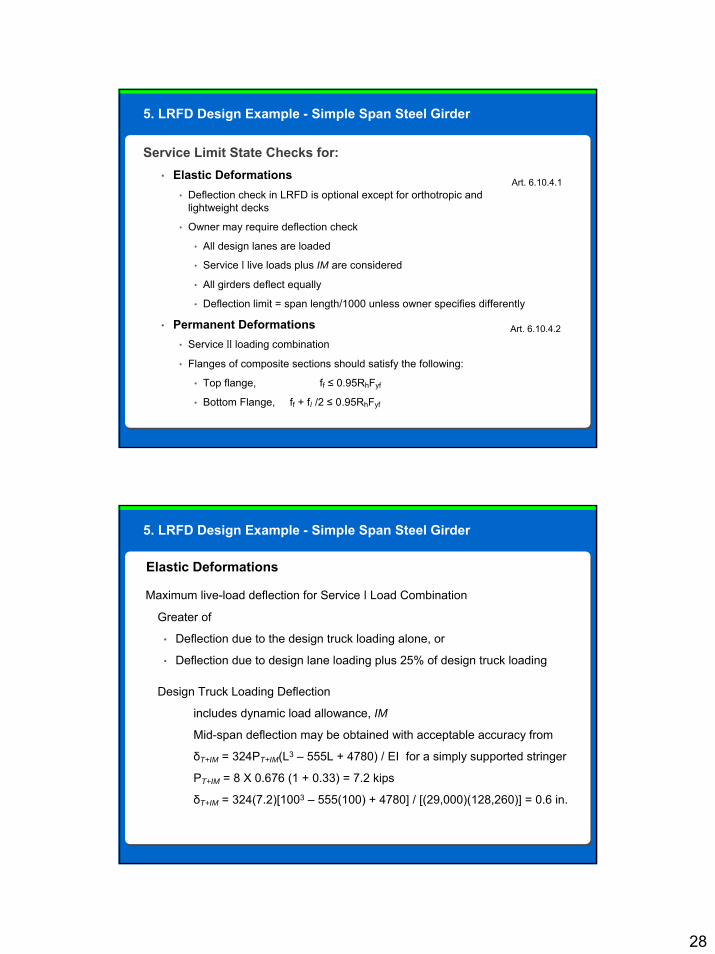
Service Limit State Checks for:• Elastic Deformations
• Deflection check in LRFD is optional except for orthotropic and lightweight decks
• Owner may require deflection check
• All design lanes are loaded
• Service I live loads plus IM are considered
• All girders deflect equally
• Deflection limit = span length/1000 unless owner specifies differently
• Permanent Deformations• Service II loading combination
• Flanges of composite sections should satisfy the following:
• Top flange, ff ≤ 0.95RhFyf
• Bottom Flange, ff + fl /2 ≤ 0.95RhFyf
Art. 6.10.4.2
Art. 6.10.4.1
5. LRFD Design Example - Simple Span Steel Girder
Maximum live-load deflection for Service I Load Combination
Greater of
• Deflection due to the design truck loading alone, or
• Deflection due to design lane loading plus 25% of design truck loading
Design Truck Loading Deflection
includes dynamic load allowance, IM
Mid-span deflection may be obtained with acceptable accuracy from
δT+IM = 324PT+IM(L3 – 555L + 4780) / EI for a simply supported stringer
PT+IM = 8 X 0.676 (1 + 0.33) = 7.2 kips
δT+IM = 324(7.2)[1003 – 555(100) + 4780] / [(29,000)(128,260)] = 0.6 in.
Elastic Deformations
5. LRFD Design Example - Simple Span Steel Girder

29
Maximum live-load deflection for Service I Load Combination
Design Lane Loading Deflectiondoes not include dynamic load allowance, IM
mid-span deflection due to uniformly distributed load from
δL = 5ωL4 / 384EI for a simply supported stringer
ωL = 0.64 X 0.676 = 0.43 kip/ft or 0.036 kip/in
δL = 5(0.036)(12004) / [384(29,000)(128,260)] + 25%(0.6) = 0.4 in.
Since δT+IM = 0.6 in > δL = 0.4 in., Truck Design Loading governs.
δT+IM = 0.6 in < L / 1000 = 1.2 in. OK
The trial section satisfies the elastic deflection requirement.
5. LRFD Design Example - Simple Span Steel Girder
A. Service Limit State Checks for• Elastic Deformations• Permanent Deformations
B. Constructability Checks for• Flexure• Shear
C. Fatigue and Fracture State Check for• Fatigue• Fracture• Special Fatigue Requirements for Web
D. Strength Limit State Check for• Flexure
• Compact or Non-compact Section• Ductility Requirement
• Shear• Check whether Web Stiffeners are required• Transverse Stiffener Design• Flange-to-Web Welds
Checks Required by the LRFD Specifications
5. LRFD Design Example - Simple Span Steel Girder

30
Flexure for Service II Load CombinationTop Flange
stresses in top flange due to short and long-term loads
[using the stresses already calculated in Table (a)]
ff ≤ 0.95RhFyf
ff = 22.51 + 0.64 + 1.3(2.04) = 25.80 ksi < 0.95(1.0)(36) = 34.2 ksi OK
Bottom Flangestresses in bottom flange due to short and long-term loads
[using the stresses already calculated in Table (a)]
ff + fl /2 ≤ 0.95RhFyf
ff + fl /2 = 13.53 + 1.05 + 1.3(9.10) + 0 = 26.41 ksi < 0.95(1.0)(36) = 34.2 ksi OK
The trial section satisfies the permanent deflection requirement.
Permanent Deformations
5. LRFD Design Example - Simple Span Steel Girder
A. Service Limit State Checks for• Elastic Deformations• Permanent Deformations
B. Constructability Checks for• Flexure• Shear
C. Fatigue and Fracture State Check for• Fatigue• Fracture• Special Fatigue Requirements for Web
D. Strength Limit State Check for• Flexure
• Compact or Non-compact Section• Ductility Requirement
• Shear• Check whether Web Stiffeners are required• Transverse Stiffener Design• Flange-to-Web Welds
Checks Required by the LRFD Specifications
5. LRFD Design Example - Simple Span Steel Girder

31
Constructibility• During critical stages of construction, nominal yielding or reliance on post-buckling resistance not permitted for main load-carrying members
• For investigating the constructibility of flexural members, all loads shall be factored
• For the calculation of deflections, the load factors shall be taken as 1.0
Constructibility Checks• Flexure Checks Art. 6.10.3.2
• Shear Check Art. 6.10.3.3
5. LRFD Design Example - Simple Span Steel Girder
Flexure Checks• For discretely braced flanges in compression
• Flange nominal yielding: fbu + fl ≤ ΦfRhFyc
• Flexural resistance: fbu + 1/3 fl ≤ ΦfFnc
• Web bend buckling: fbu ≤ ΦfFcrw
• For discretely braced flanges in tension
• Flange nominal yielding: fbu + fl ≤ ΦfRhFyt
where fbu = calculated stress due to factored dead loads = 28.13 ksi
fl = lateral bending stress in flange, ksi = 0
Φf = resistance factor for flexure = 1.00
Fnc = nominal flexure resistance of the flange = 36 ksi
Fcrw = nominal bend-buckling resistance for webs, ksi
Rh = hybrid factor = 1.0 for homogenous built-up sections
Fyt = yield strength of tension flange = 36 ksi
5. LRFD Design Example - Simple Span Steel Girder

32
Flexure Checks• For discretely braced flanges in compression
• Flange nominal yielding: fbu + fl ≤ ΦfRhFyc
28.13 + 0 < 1.00 x 1.0 x 36 ksi
28.13 < 36 ksi OKThe trial section satisfies the flange nominal yielding requirement.
5. LRFD Design Example - Simple Span Steel Girder
Flexure Checks• For discretely braced flanges in compression
• Flexural resistance: fbu + 1/3 fl ≤ ΦfFnc
Controlled by the smaller of:
Local buckling resistance of compression flange, or
Lateral torsional buckling resistance of compression flange
Local buckling resistance of compression flange, Fnc, is given by
Fnc = RbRhFyc when λf ≤ λpf
Or, otherwise,
Fnc = 1 - 1 - RbRhFyc
Fyr λf - λpf
RhFyc λfr - λpf
5. LRFD Design Example - Simple Span Steel Girder

33
Flexure Checks• For discretely braced flanges in compression
• Flexural resistance: fbu + 1/3 fl ≤ ΦfFnc
For this example,
λf = compression flange slenderness ratio, bfc / 2tfc
λpf = limiting slenderness ratio for compression flange, 0.38 √ E / Fyc
λf = 16 / (2 x 0.75) = 10.7 < λpf = 0.38 √ 29,000 / 36 = 10.8
Then, Fnc = 1.0 x 1.0 x 36 = 36 ksi
5. LRFD Design Example - Simple Span Steel Girder
Flexure Checks• For discretely braced flanges in compression
• Flexural resistance: fbu + 1/3 fl ≤ ΦfFnc
Lateral torsional buckling resistance of compression flange, Fnc, is given by
Fnc = Cb 1 - 1 - RbRhFyc ≤ RbRhFyc
where Lb = unbraced length, in., for this example 300 in.
Lp = limiting unbraced length, in., 1.0rt √ E / Fyc
Lr = π rt √ E / Fyc , in.
rt = effective radius of gyration for lateral torsional buckling, in
bfc
√ 12 (1+ 1/3(Dctw / bfctfc))
Fyr Lb - Lp
RhFyc Lr - Lp
rt =
5. LRFD Design Example - Simple Span Steel Girder

34
Flexure Checks• For discretely braced flanges in compression
• Flexural resistance: fbu + 1/3 fl ≤ ΦfFnc
Dc = web depth in compression, in
Dc = d - tfc ≥ 0
Using service limit state stresses for elastic range,
Dc = 62.25 – 0.75 = 31.34 in.
then
16
√ 12 (1 + 1/3 [ (31.34 x 7/16 ) / (16 x 0.75) ] )
-fc
fc + ft
rt = = 3.93 in.
- (-25.19)
|-25.19| + 23.68
5. LRFD Design Example - Simple Span Steel Girder
- (-25.19)
|-25.19| + 23.68
Flexure Checks• For discretely braced flanges in compression
• Flexural resistance: fbu + 1/3 fl ≤ ΦfFnc
Dc = web depth in compression, in
Dc = d - tfc ≥ 0
Using service limit state stresses for elastic range,
Dc = 62.25 – 0.75 = 31.34 in.
then
16
√ 12 (1 + 1/3 [ (31.34 x 7/16 ) / (16 x 0.75) ] )
- (-25.19)
|-25.19| + 23.68
Flexure Checks• For discretely braced flanges in compression
• Flexural resistance: fbu + 1/3 fl ≤ ΦfFnc
Lp = 1.0 x 3.93 √ (29,000 / 36) = 111.5 in.
Lr = π rt √ E / Fyc where Fyc is the smaller of 0.7Fyc = 0.7 x 36 = 25.2 ksi
or Fyw = 36 ksi
but not less than 0.5 Fyc = 0.5 x 36 = 18.0 ksi
then Lr = π 3.93 √ 29,000 / 25.2 = 418 in.
Substituting these values and conservatively taking Cb = 1.0, and Fnc = 29.4 ksi
28.13 + 0 < 1.0 x 29.4 ksi OK
The trial section satisfies the flexural resistance requirement.
5. LRFD Design Example - Simple Span Steel Girder

35
Flexure Checks• For discretely braced flanges in compression
• Flange nominal yielding: fbu + fl ≤ ΦfRhFyc
• Flexural resistance: fbu + 1/3 fl ≤ ΦfFnc
• Web bend buckling: fbu ≤ ΦfFcrw
For webs without longitudinal stiffeners
Fcrw = ≤ RhFyc or ≤ Fyw / 0.7, whichever is smaller
where k = 9 / (Dc / D)2 = 9 ( 38.17 / 60) = 22.24
in which Dc is the depth of the web in compression in elastic range
Fcrw = 0.9 x 29,000 x 22.24 / 1372 = 30.9 ksi < 1.00 x 36 ksi = 36 ksi
Fcrw = 36 / 0.7 = 51.4 ksi > 30.9 ksi therefore Fcrw = 30.9 ksi
and, since fbu = 28.13 ksi < Fcrw = 30.9 ksi
The trial section satisfies the web bend buckling requirement.
0.9 Ek
(D / tw)2
5. LRFD Design Example - Simple Span Steel Girder
A. Service Limit State Checks for• Elastic Deformations• Permanent Deformations
B. Constructability Checks for• Flexure• Shear
C. Fatigue and Fracture State Check for• Fatigue• Fracture• Special Fatigue Requirements for Web
D. Strength Limit State Check for• Flexure
• Compact or Non-compact Section• Ductility Requirement
• Shear• Check whether Web Stiffeners are required• Transverse Stiffener Design• Flange-to-Web Welds
Checks Required by the LRFD Specifications
5. LRFD Design Example - Simple Span Steel Girder

36
Constructability Checks• Shear Check
• Interior panels of the transversely stiffened webduring the critical stages of construction shall satisfythe following requirement:
Vu ≤ ΦvVcr = ΦfCVp
where Vu = shear due to factored permanentloads and factored constructionloads on the non-composite section,kips
Φv = resistance factor for shear = 1.00
Vcr = shear buckling resistance, kips
C = ratio of shear buckling resistance toshear yield strength
Vp = plastic shear force = 0.58FywDtw, kips
5. LRFD Design Example - Simple Span Steel Girder
Shear CheckVu ≤ ΦvVcr = ΦfCVp
Vu = 1.25 x 82.5 kip + 1.50 x ½ x 8.33’ x 0.100 ksf x 100’ = 144.8 kips
assuming a construction load of 0.100 ksf
C =
when D / tw ≥ 1.40 √ Ek / Fyw k = 5 +
since 60” / (7/16”) = 137 > 1.40 √ 29,000(5) / 36 = 89 k = 5 + = 5.8
assuming a transverse stiffener spacing (d0) of 150 in. for this example.
C = = 0.39
Then, Vp = 0.58 x 36 x 60 x 7/16 = 548 kips
And Vu = 144.8 < 1.00 x 0.39 x 548 = 213.7 kips OK
The trial section satisfies the shear requirement.
1.57 Ek
(D / tw)2 Fyw 5
(d0 / D)2
5
(150 / 60)2
1.57 29,000 ksi (5.8)
1372 36 ksi
5. LRFD Design Example - Simple Span Steel Girder

37
Review
Question Review
Post-buckling resistance is included in the construction stage resistance
Flexural resistance may be controlled by lateral-torsional buckling resistance
Flexural resistance may be controlled by local buckling
Web bend-buckling must be checked at the constructability level
Which is NOT a true statement regarding the LRFD constructability check?
The option Post-buckling resistance is included in the construction stage resistance is the incorrect item. LRFD does not allow web post-buckling strength to be utilized during the construction stages.

38
A. Service Limit State Checks for• Elastic Deformations• Permanent Deformations
B. Constructability Checks for• Flexure• Shear
C. Fatigue and Fracture State Check for• Fatigue• Fracture• Special Fatigue Requirements for Web
D. Strength Limit State Check for• Flexure
• Compact or Non-compact Section• Ductility Requirement
• Shear• Check whether Web Stiffeners are required• Transverse Stiffener Design• Flange-to-Web Welds
Checks Required by the LRFD Specifications
5. LRFD Design Example - Simple Span Steel Girder
Fatigue and Fracture Limit State• Fatigue Art. 6.10.5.1
• Fracture Art. 6.10.5.2
• Special Fatigue Requirements for Web Art. 6.10.5.3
5. LRFD Design Example - Simple Span Steel Girder
39
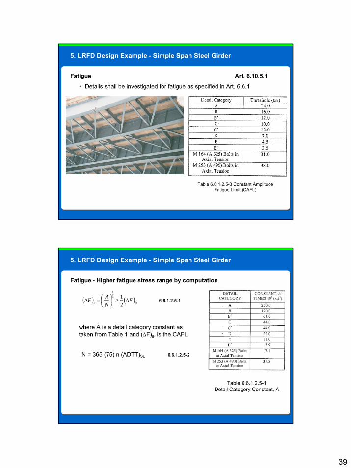
Fatigue Art. 6.10.5.1
• Details shall be investigated for fatigue as specified in Art. 6.6.1
Table 6.6.1.2.5-3 Constant Amplitude Fatigue Limit (CAFL)
5. LRFD Design Example - Simple Span Steel Girder
Fatigue - Higher fatigue stress range by computation
( ) ( ) 213
1
thn FNAF ∆≥⎟⎠⎞
⎜⎝⎛=∆
where A is a detail category constant as taken from Table 1 and (∆F)th is the CAFL
6.6.1.2.5-1
N = 365 (75) n (ADTT)SL 6.6.1.2.5-2
Table 6.6.1.2.5-1Detail Category Constant, A
5. LRFD Design Example - Simple Span Steel Girder

40
Fracture
5. LRFD Design Example - Simple Span Steel Girder
• Quality measure
• Charpy V-notch test requirements
• Fracture-critical members require
• More frequent inspections
• Higher quality control
• Increased toughness
A. Service Limit State Checks for• Elastic Deformations• Permanent Deformations
B. Constructability Checks for• Flexure• Shear
C. Fatigue and Fracture State Check for• Fatigue• Fracture• Special Fatigue Requirements for Web
D. Strength Limit State Check for• Flexure
• Compact or Non-compact Section• Ductility Requirement
• Shear• Check whether Web Stiffeners are required• Transverse Stiffener Design• Flange-to-Web Welds
Checks Required by the LRFD Specifications
5. LRFD Design Example - Simple Span Steel Girder

41
Special Fatigue Requirements for Web Art. 6.10.5.1
Interior panels of webs with or without longitudinal stiffeners shall satisfy the following requirement:
Vu ≤ Vcr
where Vu = shear in the web at the section under consideration due to un-factored permanent loads plus factored fatigue load, kips
Vcr = shear-buckling resistance determined from Vu = Vcr = CVp, kips
Vp is the plastic shear force, Vp = 548 kips and
C is the ratio of shear-buckling resistance to shear yield strength, C = 0.39 as determined earlier.
Then Vu = 0.39 x 548 = 213.7 kips
5. LRFD Design Example - Simple Span Steel Girder
Special Fatigue Requirements for Web Art. 6.10.5.1At the first interior panel, 12.5 ft from bearing, un-factored permanent load shears are
VDC = 82.5k – 12.5’ x 1.65k/’ = 61.9 kips
VDW = 8.2k – 12.5’ x 0.163k/’ = 6.2 kips
Similarly,
VFatigue = = 28.8 kips
AASHTO requires that, for the purposes of this check, the fatigue load be taken
as twice that calculated from the fatigue load combination. Then
Vu = 61.9k + 6.2k + (0.75 x 1.15 x 28.8k) 2 = 117.8 kips
Vu = 117.8 kips < Vcr = 213.7 kips OK
The web will not be subjected to significant elastic flexing.
Then Vu = 0.39 x 548 = 213.7 kips
The trial section satisfies the special fatigue requirement the web.
72k (87.5’ – 30’ + 11.78’)
100’
0.693
1.20
5. LRFD Design Example - Simple Span Steel Girder

42
A. Service Limit State Checks for• Elastic Deformations• Permanent Deformations
B. Constructability Checks for• Flexure• Shear
C. Fatigue and Fracture State Check for• Fatigue• Fracture• Special Fatigue Requirements for Web
D. Strength Limit State Check for• Flexure
• Compact or Non-compact Section• Ductility Requirement
• Shear• Check whether Web Stiffeners are required• Transverse Stiffener Design• Flange-to-Web Welds
Checks Required by the LRFD Specifications
5. LRFD Design Example - Simple Span Steel Girder
Strength Limit State Check for• Flexure
• Compact or Non-compact Section
• Ductility Requirement
• Shear• Check whether Web Stiffeners are required
• Transverse Stiffener Design
• Flange-to-Web Welds
• Bearing Stiffeners
• Shear Connectors for Composite Sections
5. LRFD Design Example - Simple Span Steel Girder

43
Flexure- Compact or Non-compact Section
Compact Section: A section in satisfying specific steel grade, web slenderness and ductility requirements that is capable of developing a nominal resistance exceeding the moment at first yield, but not to exceed the plastic moment.
Noncompact Section: A section in flexure for which the nominal resistance is not permitted to exceed the moment at first yield.
Composite section compactness requirements: Art. 6.10.6.2.2
•Yield strength of flanges, Fy < 70 ksi, Fy = 36 ksi < 70 ksi OK
•Web proportion, D / tw < 150 D / tw = 137 < 150 OK
•Web slenderness limit, 2Dcp / tw ≤ 3.76 √ E / Fyc
where Dcp is the web depth in compression.
Previously it was determined that the PNA was in the deck slab. As a result, Dcp = 0
So, web slenderness limit is also satisfied.
The section is compact provided that the following flexure requirement is met.
5. LRFD Design Example - Simple Span Steel Girder
Flexure
Flexural Resistance Art. 6.10.7
At the strength limit state, Mu + 1/3fl Sxt ≤ Φf Mn
where Φf = resistance factor for flexure = 1.00
Mn = nominal flexural resistance of the section, k-ft
Mu = factored bending moment about the major axis, k-ft
fl = lateral bending stress in flange, ksi
Sxt = elastic section modulus taken as Myt / Fyt, in3
Myt = yield moment with respect to the tension flange, k-ft
Fyt = yield strength of tension flange, ksi
In this example, Mu = 6,229 k-ft as calculated in “Loads and Load Factors” module.
5. LRFD Design Example - Simple Span Steel Girder

44
Flexure
Flexural Resistance at the strength limit state, Mu + 1/3fl Sxt ≤ Φf Mn
fl is lateral bending stress in flange due to lateral bending moment, Ml
eccentric loadings such as
- cantilever brackets of the deck forms
- loading from deck concrete pouring sequence, or
- wind loading on exterior girders between the brace points
may be calculated from Ml = Fl Lb2 / 12 or Pl Lb / 8, k-ft
In this example, it will be assumed that Ml = 0 and fl = 0.
5. LRFD Design Example - Simple Span Steel Girder
Flexure
Flexural Resistance at the strength limit state, Mu + 1/3fl Sxt ≤ Φf Mn
The nominal flexural resistance, Mn, of the composite section in positive flexural region canbe taken as
Mn = Mp when Dp ≤ 0.1 Dt
where Dp = the distance from top of concrete deck to PNA, in
and Dt = the total depth of the composite section
Dp = Y = 7.23 in from previous PNA calculation
Dt = 8.50 + 2 + 0.75 + 60 + 1.50 = 72.75 in
Thus Dp = 7.23 < 0.1 Dt = 0.1 (72.75) = 7.28 OK
Therefore Mn = Mp = 9,387 k-ft as determined before, and
since Mu + 1/3fl Sxt = 6,229 + 0 < Φf Mn = 1.00 (9,387) OK
The section satisfies the strength limit state for flexure.
5. LRFD Design Example - Simple Span Steel Girder

45
Review
Question Review
Lateral flange bending stresses due to staggered diaphragms or skewed supports
Lateral flange bending stresses due to overhang form brackets
Lateral flange bending stresses due to wind loading between diaphragms
All of the above
The strength limit state includes a check for flexural resistance: Mu + 1/3 fl Sxt. The term fl is to account for what?
The correct option is All of the above. All statements listed about the term in the flexural resistance check are correct.

46
A. Service Limit State Checks for• Elastic Deformations• Permanent Deformations
B. Constructability Checks for• Flexure• Shear
C. Fatigue and Fracture State Check for• Fatigue• Fracture• Special Fatigue Requirements for Web
D. Strength Limit State Check for• Flexure
• Compact or Non-compact Section• Ductility Requirement
• Shear• Check whether Web Stiffeners are required• Transverse Stiffener Design• Flange-to-Web Welds
Checks Required by the LRFD Specifications
5. LRFD Design Example - Simple Span Steel Girder
Flexure
Ductility Requirement Art. 6.10.7
Intended to protect the concrete deck from premature crushing
Dp ≤ 0.42 Dt Art. 6.10.7.3
where Dp = 7.23 in
and Dt = 72.75 in. as calculated before
In this design, Dp = 7.23 < 0.42 Dt = 0.42 (72.75) = 30.56 in. OK
The section satisfies the ductility requirement for flexure.
5. LRFD Design Example - Simple Span Steel Girder

47
A. Service Limit State Checks for• Elastic Deformations• Permanent Deformations
B. Constructability Checks for• Flexure• Shear
C. Fatigue and Fracture State Check for• Fatigue• Fracture• Special Fatigue Requirements for Web
D. Strength Limit State Check for• Flexure
• Compact or Non-compact Section• Ductility Requirement
• Shear• Check whether Web Stiffeners are required• Transverse Stiffener Design• Flange-to-Web Welds
Checks Required by the LRFD Specifications
5. LRFD Design Example - Simple Span Steel Girder
Shear
Shear Resistance Art. 6.10.9
At the strength limit state, straight and curved web panels must satisfy
Vu ≤ Φv Vn
where Vu = factored shear in the web at the section under consideration, kips
Φv = resistance factor for shear = 1.00 Art. 6.5.4.2
Vn = nominal shear resistance of the web, kips
unstiffened webs Art. 6.10.9.2
stiffened webs Art. 6.10.9.3
In this example, Vu = 293 kips at the bearing location as calculated in the“Loads and Load Factors” module.
5. LRFD Design Example - Simple Span Steel Girder

48
Shear
Shear Resistance Art. 6.10.9The nominal shear resistance of an unstiffened web,
Vn = Vcr = CVp
In which Vp = 0.58FywDtw, kips, and
C is determined from Eqs. 6.10.9.3.2-4, 6.10.9.3.2-5 or 6.10.9.3.2-6 as applicable
with k taken equal to 5.0
In this example, since D / tw = 137 > 1.40 √ Ek / Fyw = 89, C will be obtained from
C = = = 0.337
Thus, Vn = CVp = 0.337 x 0.58 x 36 x 60 x (7/16) = 184.7 kips < Vu = 293 kips.
Therefore, intermediate stiffeners are required for the range where Vu > 184.7 kips.
1.57 Ek
(D / tw)2 Fyw
1.57 29,000 x 5.0
(137)2 36
5. LRFD Design Example - Simple Span Steel Girder
Shear
General interior panel requirements for stiffened webs
2 D tw
( bfctfc + bfttft )
2 (60) (7/16)
16 (¾) + 20 (1 ½)
≤ 2.5 6.10.9.3.2-1
= 1.25 ≤ 2.5 OK
5. LRFD Design Example - Simple Span Steel Girder

49
A. Service Limit State Checks for• Elastic Deformations• Permanent Deformations
B. Constructability Checks for• Flexure• Shear
C. Fatigue and Fracture State Check for• Fatigue• Fracture• Special Fatigue Requirements for Web
D. Strength Limit State Check for• Flexure
• Compact or Non-compact Section• Ductility Requirement
• Shear• Check whether Web Stiffeners are required• Transverse Stiffener Design• Flange-to-Web Welds
Checks Required by the LRFD Specifications
5. LRFD Design Example - Simple Span Steel Girder
Shear
Transverse Stiffener Design Art. 6.10.11Transverse stiffener spacing for end panels with or without longitudinal stiffeners < 1.5 D
- May consist of plates or angles- May be welded or bolted to the web- May be on one side or both sides- The width should satisfy both of the following conditions:
bt ≥ 2 + d / 30 16 tp ≥ bt ≥ bf / 4
where
d = total depth of steel section, intp = thickness of projecting element, inbt = full width of widest compression
flange in a field section, in
5. LRFD Design Example - Simple Span Steel Girder

50
Shear
Transverse Stiffener Design Art. 6.10.11bt ≥ 2 + 62.25 in / 30 = 4.08 in
16 tp ≥ bt ≥ 16 in / 4 = 4.0 in
Try a pair of stiffeners plates of 6 x ½ in for the end panels.
bt = 6 in > 4.08 in OK
16 x ½ in = 8 in > bt = 6 in > 4.0 OK
5. LRFD Design Example - Simple Span Steel Girder
Shear
Transverse Stiffener Design Art. 6.10.11The moment of inertia of the transverse stiffener must satisfy:
It ≥ b tw3 J 6.10.11.1.3-1
Where
It = moment of inertia of the transverse stiffener taken about the mid-thickness of the web for stiffener pairs, in4
b = the smaller of d0 and D, in
d0 = the smaller of the adjacent web panel widths, in
J = stiffener bending rigidity parameter
tw = stiffener thickness
5. LRFD Design Example - Simple Span Steel Girder

51
Shear
Transverse Stiffener Design Art. 6.10.11
The maximum stiffener spacing in end panels is limited to 1.5D.
Maximum spacing in any other panel is limited to 3D.
3.0 D = 3.0 x 60 = 180 in
1.5 D = 1.5 x 60 = 90 in < 150 in.
Try end panel length of 75 in.
J = - 2.0 ≥ 0.5 (6.10.11.1.3-3)
J = - 2.0 = -0.4 < 0.5 Therefore, use J = 0.5
2.5
(d0 / D)2
2.5
(75 / 60)2
5. LRFD Design Example - Simple Span Steel Girder
Shear
Using It ≥ b tw3 J (6.10.11.1.3-1)
It ≥ 75” (7/16”)3 (0.5) = 3.1 in4
Actual stiffener properties are:
It = Ay2 + I0 = 2 [ 6” x ½” x (3” + 7/32”)2 + ½” (63) / 12] = 80.2 in4 > 3.1 in4 OK_
5. LRFD Design Example - Simple Span Steel Girder

52
Review
Question Review
Transverse stiffeners increase the nominal shear resistance of an unstiffened web
Transverse stiffeners may consist of plates or angles
Transverse stiffeners may be welded or bolted to the web
Transverse stiffeners may be on one side or both sides of the web
All of the above
Which of the following is correct for transverse stiffeners?
The correct option is All of the above. All statements listed about transverse stiffeners are correct.
53
A. Service Limit State Checks for• Elastic Deformations• Permanent Deformations
B. Constructability Checks for• Flexure• Shear
C. Fatigue and Fracture State Check for• Fatigue• Fracture• Special Fatigue Requirements for Web
D. Strength Limit State Check for• Flexure
• Compact or Non-compact Section• Ductility Requirement
• Shear• Check whether Web Stiffeners are required• Transverse Stiffener Design• Flange-to-Web Welds
Checks Required by the LRFD Specifications
5. LRFD Design Example - Simple Span Steel Girder
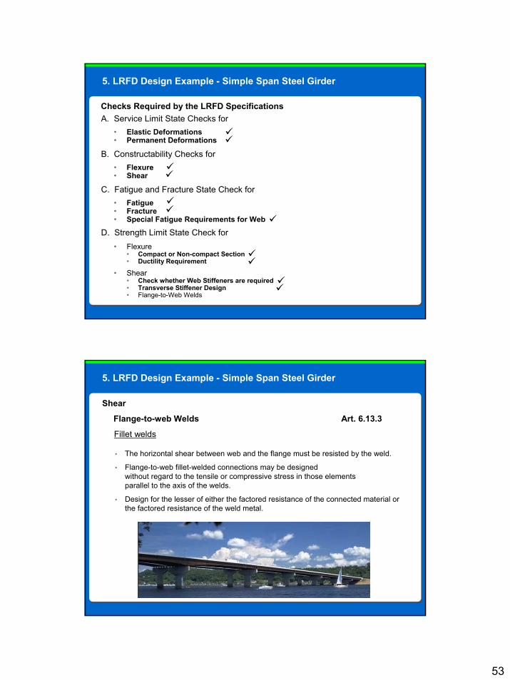
Shear
Flange-to-web Welds Art. 6.13.3
Fillet welds
• The horizontal shear between web and the flange must be resisted by the weld.
• Flange-to-web fillet-welded connections may be designed without regard to the tensile or compressive stress in those elements parallel to the axis of the welds.
• Design for the lesser of either the factored resistance of the connected material or the factored resistance of the weld metal.
5. LRFD Design Example - Simple Span Steel Girder

54
Shear
The factored resistance of the weld metal, Rr, is given as
Rr = 0.6 Φe2 Fexx
where Φe2 = resistance factor for shear in throat of weld metal = 0.80
Fexx = classification strength of weld metal = 70.0 ksi (for E70XX weld metal)
Thus, Rr = 0.6 x 0.80 x 70.0 = 33.6 ksi
Check factored base metal resistance in tension:
Fr = 0.95 x 36 ksi = 34.2 ksi Therefore Rf is still controlled by 33.6 ksi
5. LRFD Design Example - Simple Span Steel Girder
Shear
The shear between the web and flange, v = VQ / I
The factored maximum shear, V = 293.2 kips as determined before
The static moment of the flange area, Q = Af y = 1.50 x 20 x (23.33 – ½ x 1.50)
Q = 677 in3
The gross moment of inertia of the steel section, I = 42,780 in4
Thus, v = 293.3 x 677 / 42,780 = 4.64 kips/in
5. LRFD Design Example - Simple Span Steel Girder

55
Shear
Flange-to-web Welds Art. 6.13.3
The weld size required to resist the shear may be found from
v = = = 0.10 in
The minimum-size fillet weld required for a base metal thicker than 3/4 inch is 5/16 in
Therefore, use two 5/16-in continuous welds
to connect the web to the bottom flange.
v
2 lines of weld x 0.707 x Rr
4.64
2 x 0.707 x 33.6
5. LRFD Design Example - Simple Span Steel Girder

56
Review
True or False?
Flange to web welds are designed without considering the longitudinal stresses in the flange or web.
Question Review
True
False
IQVv *
= Weld demand, v, has units of kips/in
The correct option is True. Welds are designed using the maximum factored vertical shear force, not by considering longitudinal stresses in the flange or web. The shear flow formula is V Q over I, where Q is the statical moment of inertia and I is the gross moment of inertia of the steel section.
A. Service Limit State Checks for• Elastic Deformations• Permanent Deformations
B. Constructability Checks for• Flexure• Shear
C. Fatigue and Fracture State Check for• Fatigue• Fracture• Special Fatigue Requirements for Web
D. Strength Limit State Check for• Flexure
• Compact or Non-compact Section• Ductility Requirement
• Shear• Check whether Web Stiffeners are required• Transverse Stiffener Design• Flange-to-Web Welds
Checks Required by the LRFD Specifications
5. LRFD Design Example - Simple Span Steel Girder

57
5. LRFD Design Example - Simple Span Steel Girder
For a complete design
• Bearing Stiffeners
• Shear Connectors for Composite Sections
• Diaphragms and Cross Frames
• Lateral Bracings
• Splices
• Connections
1. LRFD Changes from prior Specifications
2. Analysis Options
3. Proportioning Recommendations
4. Checks Required by the LRFD Specifications
5. LRFD Design Example - Simple Span Steel Girder
6. Resources
LRFD Steel Structures
Course Outline

58
Resources
Additional Resources
• FHWA Steel Girder Design Example
• http://www.fhwa.dot.gov/bridge/lrfd/us_ds3.htm
• AISC publishing of Highway Structures Design Handbook, Volume II, Chapter 1
• “Four LRFD Design Examples of Steel Highway Bridges”
• A Fatigue Primer for Structural Engineers
• Local agencies such as MnDOT LRFD Manual
• Example of 2-span steel girder bridge
• The three areas where the LRFD code changes past practice of steel structures design
• The basic proportioning of economic steel structures
• Applications of the LRFD design philosophy to basic steel structures
• The checks required in steel girder design
• The resources and alternate examples available to designers
Objective Review
We have now covered all of the objectives of the class. You should now be able to identify the following:

59
Mahir Sen, P.E.
Paul Pilarski, P.E., S.E.
Credits
The content for this class has been provided by the following PB employees:
Reference:
Structural Steel Designer’s Handbook
Brockenbrough - Merritt, Fourth Edition, McGraw Hill, 2006
If you have any questions about the content of this course please contact Mahir Sen or email [email protected].
Instructions
• The assessment consists of 10 multiple choice questions.
• You will need to achieve a minimum score of 80% to receive credit for passing the course.
• If you score below 80%, please go back and review the content of this course, and then retake the assessment to achieve a passing score.
You are now ready to begin the final assessment.
When ready, click the Right arrow below to advance to the assessment.
Final Assessment

60
Thank you for completing this course. If you received a passing score on the assessment, simply close this window to exit the course. Your score will be recorded on your transcript.
If you did not achieve a passing score, please review the content of this course and then retake the assessment to achieve a passing score.
If you have any questions or problems with the functionality of this course, please email us at [email protected] and specify the name of the course and the issue you are experiencing so that we may assist you.
Conclusion