Embed Size (px)
Citation preview

STEENBRAS WATER TREATMENT PLANT
MICRO HYDROELECTRIC TURBINE INVESTIGATION
Garth Aspeling, Mechatronic Engineer and Mlamli Mabulu, Chief
Mechanical Engineer , Water and Sanitation Department, Utilities
Services Directorate, City of Cape Town, South Africa
CONTENTS
• Project Purpose
• Treatment Plant Overview
• Data Capturing and Analysis
• Design Analysis
• Conclusion and Recommendation

PROJECT PURPOSE
• Investigate the 70 year old turbine installation
• Evaluate existing turbine performance
• Identify maintenance costs
• Evaluate new design options
• Optimise any underutilised flow
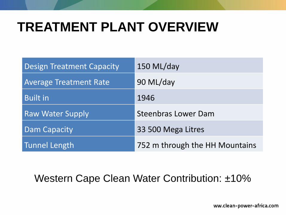
TREATMENT PLANT OVERVIEW
Design Treatment Capacity 150 ML/day
Average Treatment Rate 90 ML/day
Built in 1946
Raw Water Supply Steenbras Lower Dam
Dam Capacity 33 500 Mega Litres
Tunnel Length 752 m through the HH Mountains
Western Cape Clean Water Contribution: ±10%

GORDONS BAY STEENBRAS LOWER DAM
STEENBRAS WTP
INLET TOWER SCREEN CHAMBER
ROCKVIEW DAM
STEENBRAS UPPER DAM
DISTRIBUTION

ELECTRICAL SUPPLY LAYOUT
• No Eskom backup supply

Total Installed Capacity 320 kW
Turbine no. 1 160 kW
Turbine no. 2 160 kW
Installation Date 1948
Manufacturer Gilkes (London)
Size and Type 2 x 21” Turgo Impulse
Jet Arrangement Single Jet
Turbine Arrangement Tandem Runners
Normal Speed 428 rpm
Net Head 34.44 m
Flow Rate at full load 0.66 m3 /s (57 Ml/d)
Weight of Runner 285 kg
EXISTING TURBINE SPECIFICATIONS

EXISTING TURBINE LAYOUT
Spear Valve
Spear Valve
Hydraulic Governor
In-Flow
Turgo Runner
Generator
Fly Wheel (safety guard)
Deflector Plate Control

HISTORICAL FLOW DATA - 8 YEARS
0
20
40
60
80
100
120
140
160
28-Sep-04 28-Sep-05 28-Sep-06 28-Sep-07 28-Sep-08 28-Sep-09 28-Sep-10 28-Sep-11
Flo
w R
ate
(M
l/d
)
Year
Ml/d m3/s
Max 148.4 1.72
Avg 90.2 1.04

MEASUREMENTS – TURBINE 2
Readings Taken Data
Net pressure reading 3.11 bar
Total Flow Rate 81.9 Ml/d
Turbine Flow Rate 54 Ml/d
Power Factor - 0.69
Power Reading 89 kW
Frequency 50,2 Hz
Variables
H 31.1 m
P 89 kW
Q 0.625
= 47 % Plant utilisation of energy

DESIGN ANALYSIS
=
= Select Design Capacity Factor @ 95 %
ρ = 1000 kg/m3 g = 9.81 m/s2
Prated = Determine
Case 1 Plant Layout Analysis
Case 2 Refurbishment of Equipment Controls

DESIGN CAPACITY FACTOR
0.0
0.2
0.4
0.6
0.8
1.0
1.2
1.4
1.6
1.8
2.0
0 10 20 30 40 50 60 70 80 90 100
Flo
w r
ate
(m
^3/s
)
Exceedance Probability (%)

Hstat
TRANSFER CHAMBER
POWER HOUSE
HYDROPOWER CHARACTERSITICS
• Penstock length = 185 m
• Penstock Ø = 800 mm
• Hstat = 36.58 m
• Turbine Power out = 160kW

Rated Flow = 0.65 m3/s Rated Head = 31.2 m
Min. Head = 30 m Max. Head = 35 m
Rated Power = 160 kW Load Factor > 20 %
Peak Mechanical Efficiency = 90 %
Turbine Design Parameters
RATED POWER GENERATION

26
27
28
29
30
31
32
33
34
35
36
0.500 0.550 0.600 0.650 0.700
Net
He
ad (
m)
Q (m3/s)
RATED POWER GENERATION
Pr = 160 kW

POWER AND HEAD DURATION CURVES
0
25
50
75
100
125
150
175
200
225
0
5
10
15
20
25
30
35
40
0% 5% 10% 15% 20% 25% 30% 35% 40% 45% 50% 55% 60% 65% 70% 75% 80% 85% 90% 95% 100%
Po
we
r (k
W)
He
ad (
m)
Assurance
Head (m) Actual Power (kW)
160 kW @ 31.2m

TURBINE SELECTION
31.2 m
0.65

FRANCIS vs TURGO TURBINE
0%
10%
20%
30%
40%
50%
60%
70%
80%
90%
100%
110%
0% 10% 20% 30% 40% 50% 60% 70% 80% 90% 100%
Turb
ine
Re
lati
ve E
ffic
en
cy
Percent of Full Flow
Efficiency Comparison
Single Jet Turgo Turbine
0%
10%
20%
30%
40%
50%
60%
70%
80%
90%
100%
110%
0% 10% 20% 30% 40% 50% 60% 70% 80% 90% 100%
Turb
ine
Re
lati
ve E
ffic
en
cy
Percent of Full Flow
Efficiency Comparison
Francis Turbine

REFURBISHMENT OF CONTROL EQUIPMENT
Item Quantity Estimate Total Price
Electric Governor Package 2 R2 million
Step-up Gearbox and Generator 1 R800 000
Existing mechanical governor Step-up gearbox

CONCLUSION AND RECOMMENDATION
Case 1: Plant Analysis
Original plant turbines still match the existing water treatment plant flow supply and operating pressures.
Power station is under utilised (an excess power of ± 30 % is not utilised)
More hydropower site locations have been explored and this power can be utilised elsewhere in the plant
Provision (e.g. workshop) to utilise full rated power in the plant will be useful
Case 2: Refurbishment of Control Equipment
Step-up Gear Box
Governor Control can be refurbished to modern designs.

QUESTIONS
?
This presentation was made possible by the Water and Sanitation section, CoCT.
Thanks for everyone's input and help and a special thanks to the Bulk Water Department.