Embed Size (px)
Citation preview

EK-LM3S811-01 Copyr ight © 2006 Luminary Micro, Inc.
Stellaris® LM3S811Evaluation Board
USER ’S MANUAL

2 December 22, 2006
Legal Disclaimers and Trademark InformationINFORMATION IN THIS DOCUMENT IS PROVIDED IN CONNECTION WITH LUMINARY MICRO PRODUCTS. NO LICENSE, EXPRESS OR IMPLIED, BY ESTOPPEL OR OTHERWISE, TO ANY INTELLECTUAL PROPERTY RIGHTS IS GRANTED BY THIS DOCUMENT. EXCEPT AS PROVIDED IN LUMINARY MICRO’S TERMS AND CONDITIONS OF SALE FOR SUCH PRODUCTS, LUMINARY MICRO ASSUMES NO LIABILITY WHATSOEVER, AND LUMINARY MICRO DISCLAIMS ANY EXPRESS OR IMPLIED WARRANTY, RELATING TO SALE AND/OR USE OF LUMINARY MICRO’S PRODUCTS INCLUDING LIABILITY OR WARRANTIES RELATING TO FITNESS FOR A PARTICULAR PURPOSE, MERCHANTABILITY, OR INFRINGEMENT OF ANY PATENT, COPYRIGHT OR OTHER INTELLECTUAL PROPERTY RIGHT. LUMINARY MICRO’S PRODUCTS ARE NOT INTENDED FOR USE IN MEDICAL, LIFE SAVING, OR LIFE-SUSTAINING APPLICATIONS.
Luminary Micro may make changes to specifications and product descriptions at any time, without notice. Contact your local Luminary Micro sales office or your distributor to obtain the latest specifications before placing your product order.
Designers must not rely on the absence or characteristics of any features or instructions marked "reserved" or "undefined." Luminary Micro reserves these for future definition and shall have no responsibility whatsoever for conflicts or incompatibilities arising from future changes to them.
Copyright © 2006 Luminary Micro, Inc. All rights reserved. Stellaris is a registered trademark, and the Luminary Micro logo is a trademark of Luminary Micro, Inc. or its subsidiaries in the United States and other countries. ARM and Thumb are registered trademarks, and Cortex is a trademark of ARM Limited. Other names and brands may be claimed as the property of others.
Luminary Micro, Inc.108 Wild Basin, Suite 350Austin, TX 78746Main: +1-512-279-8800Fax: +1-512-279-8879http://www.luminarymicro.com

Stellaris® LM3S811 Evaluation Board
Revision HistoryThis table provides a summary of the document revisions.
Date Revision Description
September 2006 00 Initial release of doc to customers.
December 2006 01 Changed value in Table C-1 for Pad 11.
December 22, 2006 3

4 December 22, 2006
Stellaris® LM3S811 Evaluation Board
Table of ContentsChapter 1: Stellaris® LM3S811 Evaluation Board ......................................................................................... 9Features.............................................................................................................................................................. 9Block Diagram .................................................................................................................................................. 10Evaluation Kit Contents .................................................................................................................................... 10
Evaluation Board Specifications ................................................................................................................... 10System Requirements................................................................................................................................... 11Supported Devices........................................................................................................................................ 11
Features of the LM3S811 Microcontroller......................................................................................................... 11
Chapter 2: Getting Started ............................................................................................................................. 13Powering the Board .......................................................................................................................................... 13Installing the Drivers ......................................................................................................................................... 13
Driver Installation .......................................................................................................................................... 13Completing Driver Installation ....................................................................................................................... 13
Running the Quickstart Application................................................................................................................... 14
Chapter 3: Hardware Description.................................................................................................................. 15LM3S811 Microcontroller .................................................................................................................................. 15
Device Overview ........................................................................................................................................... 15Clocking ........................................................................................................................................................ 15Reset............................................................................................................................................................. 15Power Supply................................................................................................................................................ 15Debugging..................................................................................................................................................... 15
USB Device Controller Functions ..................................................................................................................... 16Device Overview ........................................................................................................................................... 16USB to JTAG/SWD....................................................................................................................................... 16Virtual COM Port........................................................................................................................................... 16
Organic LED Display ........................................................................................................................................ 16Features........................................................................................................................................................ 16Control Interface ........................................................................................................................................... 16Power Supply................................................................................................................................................ 17Design Guidelines......................................................................................................................................... 17Further Reference......................................................................................................................................... 17
Other Peripherals.............................................................................................................................................. 17Thumbwheel Potentiometer .......................................................................................................................... 17User LED ...................................................................................................................................................... 17User Pushbutton ........................................................................................................................................... 17
Bypassing Peripherals ...................................................................................................................................... 17Interfacing to the EVB....................................................................................................................................... 18Using the In-Circuit Debugger Interface ........................................................................................................... 18
ICDI Features................................................................................................................................................ 18Enabling ICDI Mode...................................................................................................................................... 19ARM Target Cable ........................................................................................................................................ 19Starting ICDI ................................................................................................................................................. 19
December 22, 2006 5
Stellaris® LM3S811 Evaluation Board
Chapter 4: Communications.......................................................................................................................... 21Using the Virtual COM Port .............................................................................................................................. 21
Confirming Driver Installation........................................................................................................................ 21Installing the VCP Device Driver................................................................................................................... 22
About HyperTerminal ........................................................................................................................................ 24Starting HyperTerminal ................................................................................................................................. 24
Appendix A: Contact Information ................................................................................................................. 27Appendix B: Schematics................................................................................................................................ 29Appendix C: Connection Details ................................................................................................................... 33Component Locations....................................................................................................................................... 33Evaluation Board Dimensions........................................................................................................................... 33I/O Breakout Pads and Recommended Connectors......................................................................................... 34ARM Target Pinout ........................................................................................................................................... 35
December 22, 2006 6
Stellaris® LM3S811 Evaluation Board
December 22, 2006 7
List of FiguresFigure 1-1. Evaluation Board Layout ................................................................................................................. 9Figure 1-2. LM3S811 Evaluation Board Block Diagram .................................................................................. 10Figure 3-1. ICD Interface Mode ....................................................................................................................... 18Figure 4-1. Check VCP Driver Installation ....................................................................................................... 21Figure B-1. LM3S811 Microcontroller (sheet 1 of 2) ........................................................................................ 30Figure B-2. LM3S811 Microcontroller (sheet 2 of 2) ........................................................................................ 31Figure C-1. Component Locations ................................................................................................................... 33Figure C-2. Evaluation Board Dimensions ....................................................................................................... 33
Stellaris® LM3S811 Evaluation Board
December 22, 2006 8
List of TablesTable 3-1. Isolating On-Board Hardware........................................................................................................ 18Table C-1. I/O Breakout Pads ......................................................................................................................... 34Table C-2. Recommended Connectors........................................................................................................... 34Table C-3. 20-Pin JTAG/SWD Configuration .................................................................................................. 35
C H A P T E R 1
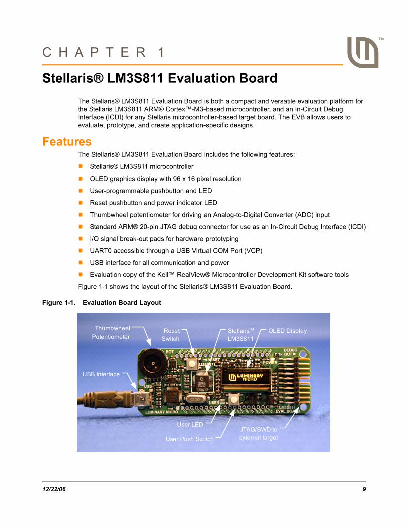
Stellaris® LM3S811 Evaluation BoardThe Stellaris® LM3S811 Evaluation Board is both a compact and versatile evaluation platform for the Stellaris LM3S811 ARM® Cortex™-M3-based microcontroller, and an In-Circuit Debug Interface (ICDI) for any Stellaris microcontroller-based target board. The EVB allows users to evaluate, prototype, and create application-specific designs.
FeaturesThe Stellaris® LM3S811 Evaluation Board includes the following features:
Stellaris® LM3S811 microcontroller
OLED graphics display with 96 x 16 pixel resolution
User-programmable pushbutton and LED
Reset pushbutton and power indicator LED
Thumbwheel potentiometer for driving an Analog-to-Digital Converter (ADC) input
Standard ARM® 20-pin JTAG debug connector for use as an In-Circuit Debug Interface (ICDI)
I/O signal break-out pads for hardware prototyping
UART0 accessible through a USB Virtual COM Port (VCP)
USB interface for all communication and power
Evaluation copy of the Keil™ RealView® Microcontroller Development Kit software tools
Figure 1-1 shows the layout of the Stellaris® LM3S811 Evaluation Board.
Figure 1-1. Evaluation Board Layout
Thumbwheel
Potentiometer
USB Interface
User LED
User Push Switch
OLED DisplayStellarisTM
LM3S811Reset
Switch
JTAG/SWD to external target
12/22/06 9

Block Diagram
Block DiagramFigure 1-2. LM3S811 Evaluation Board Block Diagram
Evaluation Kit ContentsThe evaluation kit contains everything needed to develop and run applications for Stellaris microcontrollers including:
LM3S811 Evaluation Board (EVB)
USB cable
20-pin JTAG/SWD target cable
CD containing:
– Keil™ RealView® Microcontroller Development Kit RVMDK (16 KB limited)
– Complete documentation
– Quickstart guide
– Quickstart source code
– DriverLib and example source code
Evaluation Board SpecificationsBoard supply voltage: 4.37–5.25 Vdc from USB connector
Board supply current: 80 mA typ (fully active, CPU at 50 MHz)
Break-out power output: 3.3 Vdc (100 mA max)
USB
StellarisLM3S811
MCU
+5V
DualUSB
DeviceController I/O
Sig
nals
OLED Display96 x 16
Deb
ug
Switch
Pot
LED
I/O Signal Break-out
I/O Signal Break-out
20-pin ARM JTAG/SWD Output
USB Cable
Reset
+3.3V Voltage Regulator
SW
D/J
TAG
M
ux
UART0
Reset
Targ
et
Cab
le
10 12/22/06
Stellaris® LM3S811 Evaluation Board
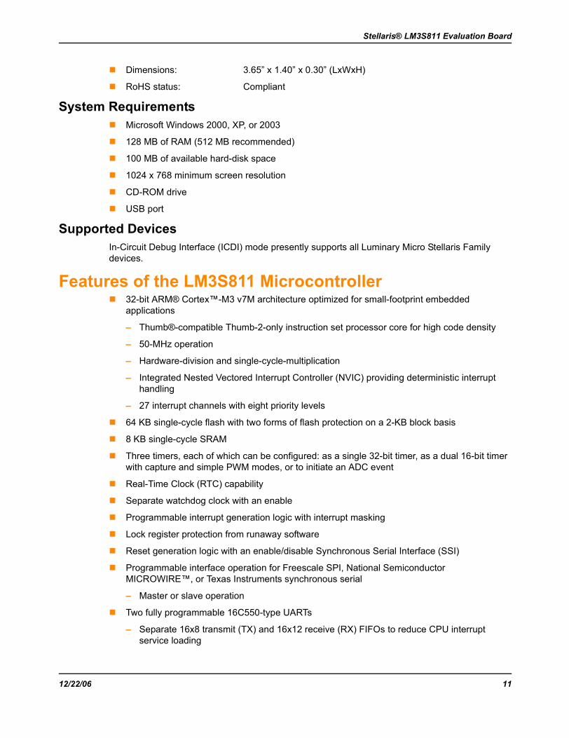
Dimensions: 3.65” x 1.40” x 0.30” (LxWxH)
RoHS status: Compliant
System RequirementsMicrosoft Windows 2000, XP, or 2003
128 MB of RAM (512 MB recommended)
100 MB of available hard-disk space
1024 x 768 minimum screen resolution
CD-ROM drive
USB port
Supported DevicesIn-Circuit Debug Interface (ICDI) mode presently supports all Luminary Micro Stellaris Family devices.
Features of the LM3S811 Microcontroller32-bit ARM® Cortex™-M3 v7M architecture optimized for small-footprint embedded applications
– Thumb®-compatible Thumb-2-only instruction set processor core for high code density
– 50-MHz operation
– Hardware-division and single-cycle-multiplication
– Integrated Nested Vectored Interrupt Controller (NVIC) providing deterministic interrupt handling
– 27 interrupt channels with eight priority levels
64 KB single-cycle flash with two forms of flash protection on a 2-KB block basis
8 KB single-cycle SRAM
Three timers, each of which can be configured: as a single 32-bit timer, as a dual 16-bit timer with capture and simple PWM modes, or to initiate an ADC event
Real-Time Clock (RTC) capability
Separate watchdog clock with an enable
Programmable interrupt generation logic with interrupt masking
Lock register protection from runaway software
Reset generation logic with an enable/disable Synchronous Serial Interface (SSI)
Programmable interface operation for Freescale SPI, National Semiconductor MICROWIRE™, or Texas Instruments synchronous serial
– Master or slave operation
Two fully programmable 16C550-type UARTs
– Separate 16x8 transmit (TX) and 16x12 receive (RX) FIFOs to reduce CPU interrupt service loading
12/22/06 11
Features of the LM3S811 Microcontroller
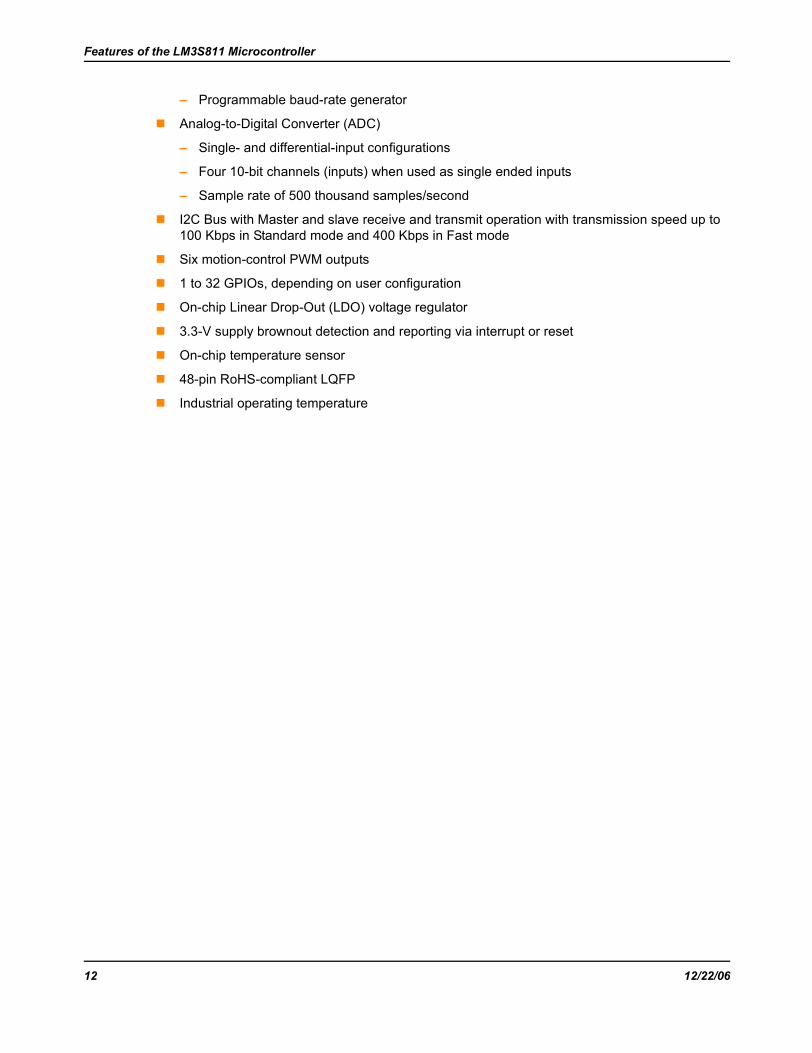
– Programmable baud-rate generator
Analog-to-Digital Converter (ADC)
– Single- and differential-input configurations
– Four 10-bit channels (inputs) when used as single ended inputs
– Sample rate of 500 thousand samples/second
I2C Bus with Master and slave receive and transmit operation with transmission speed up to 100 Kbps in Standard mode and 400 Kbps in Fast mode
Six motion-control PWM outputs
1 to 32 GPIOs, depending on user configuration
On-chip Linear Drop-Out (LDO) voltage regulator
3.3-V supply brownout detection and reporting via interrupt or reset
On-chip temperature sensor
48-pin RoHS-compliant LQFP
Industrial operating temperature
12 12/22/06

C H A P T E R 2
Getting StartedThe Stellaris LM3S811 Evaluation Kit EKK-LM3S811 Quickstart provides step-by-step instructions for getting started with your Stellaris LM3S811 Evaluation Kit. For your convenience these instructions are summarized below.
Powering the BoardThe Stellaris LM3S811 Evaluation Board (EVB) is configured for immediate use. To power the EVB, use the USB cable supplied in the kit. Connect the mini-b (smaller) end of the USB cable to the connector labeled “USB” on the EVB. Connect the other end (Type A) to a free USB port on your host PC. The USB interface is capable of sourcing up to 500 mA for each attached device, which is sufficient for the evaluation board. If connecting the board through a USB hub, it must be a powered hub.
When you plug in the EVB for the first time, Windows starts the Found New Hardware Wizard. The Stellaris LM3S811 Evaluation Kit Quickstart Guide steps through the process of installing drivers for the Stellaris LM3S811 Evaluation Board.
Installing the DriversThe Stellaris LM3S811 Evaluation Board requires several hardware drivers. All drivers are located in the \Tools\Ftdi directory on the Software and Documentation CD. Each time Windows requests a driver for this device, point it to the Software and Documentation CD.
Driver InstallationWhen the Found New Hardware Wizard starts, Windows asks if it can connect to Windows Update to search for software. Select “No, not this time,” and then click Next.
The Found New Hardware Wizard then asks you from where to install the software. Select “Install from a list or specific location (Advanced)” and click Next.
Make sure the Documentation and Software CD that came with the evaluation kit is in your CD-ROM drive. Select “Search for the best driver in these locations,” and check the “Search removable media (floppy, CD-ROM…)” option. Click Next.
A warning pops up during the Hardware Installation; click Continue Anyway.
Windows now finishes installing the drivers for “LM3S811 Evaluation Board A.” When the driver install is finished, a window appears. Click Finish to close the dialog box.
Completing Driver InstallationYou have just installed the drivers for “LM3S811 Evaluation Board A”. The USB device built into the EVB is a composite USB device. After you click Finish, a new Found New Hardware Wizard window appears asking to install drivers for another device. This is for the “LM3S811 Evaluation Board B” part of the composite USB device. Follow the same instructions as above to install the drivers for this device.
The Found New Hardware Wizard appears one last time. This is to install the drivers for the “LM3S811 Virtual COM Port”. Again, follow the same instructions above to install the drivers for this device.
12/22/06 13

Getting Started
Now all of the hardware drivers for the LM3S811 Evaluation Board have been installed. These drivers give the debugger access to the JTAG interface and the host PC access to the Virtual COM Port.
Running the Quickstart ApplicationThe quickstart application is a game in which you navigate a ship through an endless tunnel. Use the potentiometer (POT) to move the ship up and down, and the user pushbutton (USER) to fire a missile to destroy obstacles in the tunnel. Score accumulates for survival and destroying obstacles. The game lasts for only one ship; the score displays at the end of the game.
Since the OLED display on the evaluation board has burn-in characteristics similar to a CRT, the application also contains a screen saver. The screen saver only becomes active if two minutes have passed without the user pushbutton being pressed while waiting to start the game (i.e., the screen saver never appears during game play). An implementation of the Game of Life is run with a field of random data as the seed value.
After two minutes of running the screen saver, the display turns off and the user LED blinks. Exit either mode of screen saver (Game of Life or blank display) by pressing the user pushbutton (USER). Press the button again to start the game.
While the game is being played, a running tally of the score is output through UART0 of the LM3S811. UART0 is connected to the FTDI’s second serial channel. This serial channel is available to Windows as a Virtual COM Port. To view the score, open up a terminal application such as HyperTerminal. Connect using COM#, where # is the number Windows has assigned the Virtual COM Port. Set the serial connection to a baud rate of 115200, 8 data bits, no parity, 1 stop bit, and no flow control.
Important: The quickstart application will not run if one or more jumpers are removed.
14 12/22/06
C H A P T E R 3
Hardware DescriptionThis chapter provides the hardware description for the LM3S811 microcontroller including the peripherals included in the evaluation kit.
LM3S811 MicrocontrollerDevice Overview
The heart of the EVB is a Stellaris LM3S811 ARM® Cortex™-M3-based microcontroller. The LM3S811 offers 64 KB flash memory, 50-MHz operation, a 4-channel ADC, and a wide range of peripherals. Refer to the LM3S811 data sheet (order number DS-LM3S811) for complete device details.
The LM3S811 microcontroller is factory programmed with a quickstart demo program. The quickstart program resides in the LM3S811 on-chip flash memory and runs each time power is applied, unless ICDI mode is in use, or the quickstart has been replaced with a user program.
ClockingA single external 6.0-Mhz crystal drives the LM3S811 microcontroller. All required internal clocks are generated automatically within the device. The LM3S811 microcontroller is designed to run the ARM Cortex core at 50 Mhz on this evaluation board.
ResetThe LM3S811 microcontroller shares its external reset input with the OLED display. Reset is asserted (Active Low) under any one of the following conditions:
Power-on reset (duration set by resistor R1 and capacitor C17)
Reset switch SW2 is held down
In ICDI mode
By the USB device controller (U2 FT2232), when instructed by the debugger
The Keil RVMDK debugger does not support external reset. Instead, the target device is reset using JTAG operations. In ICDI mode, the reset push-switch has no effect.
Power SupplyThe LM3S811 is powered from a +3.3-V supply rail that is common to all devices on the EVB. A low-dropout (LDO) regulator regulates +5 V power from the USB cable to +3.3 V. +3.3 V at up to 100 mA is available for powering external circuits at break-out pin 20.
DebuggingStellaris microcontrollers support programming and debugging using either JTAG or SWD. JTAG uses the TCK, TMS, TDI, and TDO signals. SWD requires fewer signals—SWCLK, SWDIO, and SWO. The debugger determines which debug protocol is used. For example, Keil RVMDK tools support only JTAG debugging.
12/22/06 15
Hardware Description
JTAG/SWD signals are multiplexed with GPIO functions inside the Stellaris microcontroller. Do not configure JTAG/SWD pins (including PB7/TRST) as GPIO. Doing this prevents in-circuit programming and debugging.
USB Device Controller FunctionsDevice Overview
An FT2232 device from Future Technology Devices International Ltd manages USB-to-serial conversion. The FT2232 is factory configured by Luminary Micro to implement a JTAG/SWD port (synchronous serial) on channel A and a Virtual COM Port (VCP) on channel B. This feature allows two simultaneous communications links between the host computer and the target device using a single USB cable. Separate Windows drivers for each function are provided on the Documentation and Software CD.
A small serial EEPROM holds the FT2232 configuration data. The EEPROM is not accessible by the LM3S811 microcontroller.
For full details on FT2232 operation, go to www.ftdichip.com.
USB to JTAG/SWDThe FT2232 USB device performs JTAG/SWD serial operations under the control of the debugger. Two 74LV125 hex buffers multiplex SWD and JTAG functions and provide direction control for the bi-directional data line when working in SWD mode.
Virtual COM PortThe Virtual COM Port (VCP) allows Windows applications (such as HyperTerminal) to communicate with UART0 on the LM3S811 over USB. Once the FT2232 VCP driver is installed, Windows assigns a COM port number to the VCP channel.
For more information, see Using the Virtual COM Port on page 21.
Organic LED DisplayThe EVB features an Organic LED (OLED) graphics display with 96 x 16 pixel resolution. OLED is a new technology that offers many advantages over LCD display technology.
FeaturesOsram OS096016 series display
96 columns by 16 rows
1 bit/pixel monochrome
High-contrast (typ. 2000:1)
Excellent brightness (120 cd/m2)
Fast response
Control InterfaceThe OLED display has a built-in controller IC (SSD0303) with synchronous serial and I2C interfaces. I2C is used on the EVB as it only requires two microcontroller pins. The OLED display has a fixed I2C address of 0x3d. The Stellaris driver library (DriverLib) (included on the
16 12/22/06

Stellaris® LM3S811 Evaluation Board
Documentation and Software CD) contains complete drivers with source-code for the OLED display.
Note that the SSD0303’s I2C bus implementation is not 100% compliant with the I2C specification. Designers should refer to the SSD0303 datasheet before connecting other I2C devices to the bus.
Power SupplyA +9 V supply is needed to bias the OLED display. Conveniently, the SSD0303 IC includes an on-chip voltage boost controller. A few external components complete the simple switching power supply. This supply is dedicated to the OLED display and should not be used to power other devices.
Design GuidelinesThe OLED display has a lifetime of about 10,000 hours. It is also prone to degradation due to burn-in, similar to CRT and plasma displays. The quickstart application includes both a screen-saver and a power-down mode to extend display life. These factors should be considered when developing EVB applications that use the OLED display.
When using the EVB as an In-Circuit Debug Interface (ICDI), the OLED display is held in reset to reduce power consumption and eliminate display wear-out.
Further ReferenceFor additional information on the OS096016 OLED display, visit www.osram-os.com.
Full details on the SSD0303 controller are available from Solomon Systech, Ltd. (www.solomon-systech.com).
Other PeripheralsThumbwheel Potentiometer
A thumbwheel potentiometer connects to Channel 0 of the Analog-to-Digital Converter (ADC). A padding resistor (R31) sets the voltage range to 0 to 3.0 V. This corresponds with the full-scale range of the LM3S811’s 10-bit ADC. The ADC input voltage increases with clockwise potentiometer rotation.
User LEDA user LED (D2) is provided for general use. The LED is connected to PC5/CCP1, allowing the option of either GPIO or PWM control (brightness control). Refer to the Quickstart Application source code for an example of PWM control.
User PushbuttonA user pushbutton (SW1) is provided for general use. The switch interfaces to PC4 of the LM3S811.
Bypassing PeripheralsThe EVB’s on-board peripheral circuits require seven GPIO lines, leaving up to 25 GPIO lines immediately available for connection to external circuits. If all GPIO lines are needed, then the on-board hardware can be bypassed. The EVB is populated with seven 0-ohm resistor jumpers, which can be removed to isolate on-board hardware.
12/22/06 17
Hardware Description
Important: The quickstart application will not run if one or more jumpers are removed.
Interfacing to the EVBAn array of accessible I/O signals makes it easy to interface the EVB to external circuits. All LM3S811 I/O lines (except those with JTAG functions) are brought out to 0.1” pitch pads. For quick reference, silk-screened labels on the PCB show primary pin functions.
Table C-1 on page 34 has a complete list of I/O signals as well as recommended connectors.
Most LM3S811 I/O signals are +5-V tolerant. 5-V tolerant pins will not be damaged when connected to 5-V logic circuits. It is recommended that datasheets be checked for compatibility when mixing logic types. Refer to the LM3S811 datasheet for detailed electrical specifications.
Using the In-Circuit Debugger InterfaceThe Stellaris LM3S811 Evaluation Kit can operate as an In-Circuit Debugger Interface (ICDI). ICDI acts as a USB to the JTAG/SWD adaptor, allowing debugging of any external target board that uses a Stellaris microcontroller.
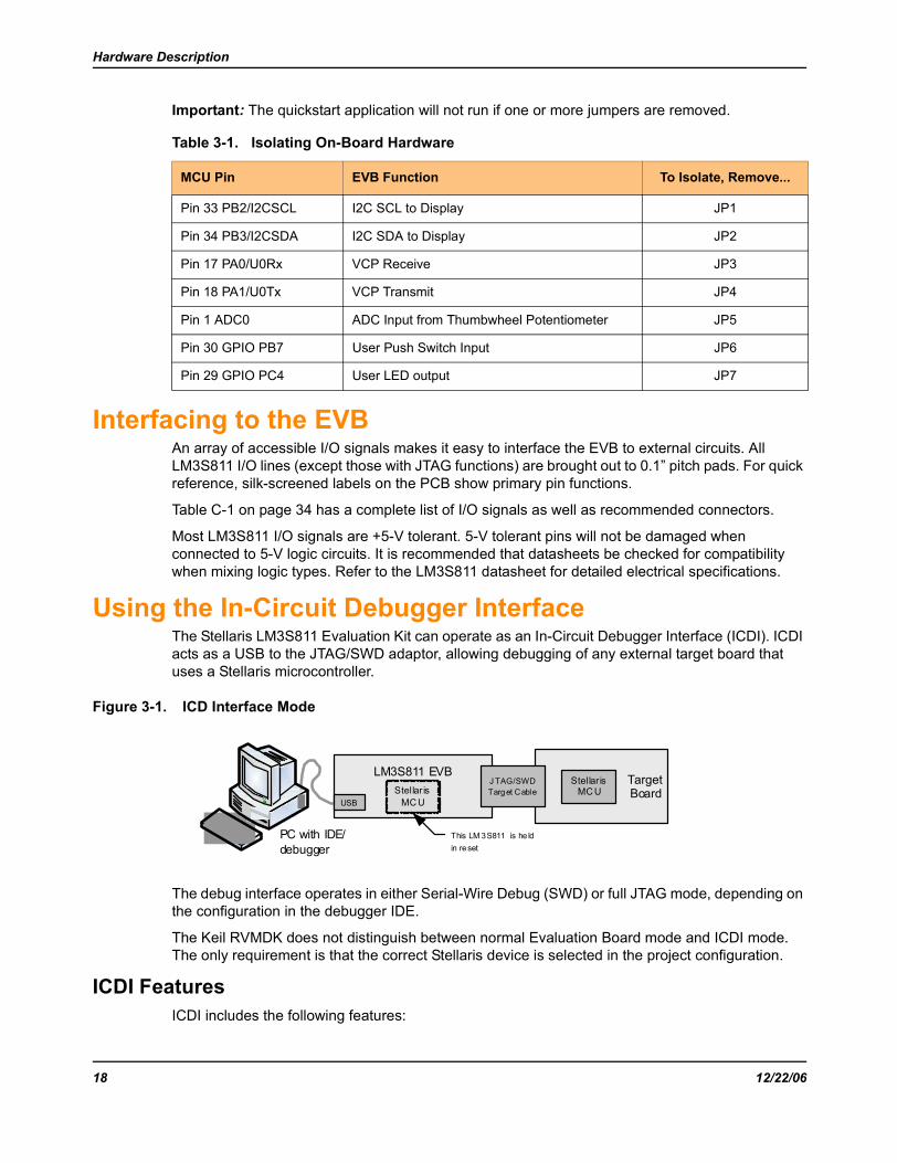
Figure 3-1. ICD Interface Mode
The debug interface operates in either Serial-Wire Debug (SWD) or full JTAG mode, depending on the configuration in the debugger IDE.
The Keil RVMDK does not distinguish between normal Evaluation Board mode and ICDI mode. The only requirement is that the correct Stellaris device is selected in the project configuration.
ICDI FeaturesICDI includes the following features:
Table 3-1. Isolating On-Board Hardware
MCU Pin EVB Function To Isolate, Remove...
Pin 33 PB2/I2CSCL I2C SCL to Display JP1
Pin 34 PB3/I2CSDA I2C SDA to Display JP2
Pin 17 PA0/U0Rx VCP Receive JP3
Pin 18 PA1/U0Tx VCP Transmit JP4
Pin 1 ADC0 ADC Input from Thumbwheel Potentiometer JP5
Pin 30 GPIO PB7 User Push Switch Input JP6
Pin 29 GPIO PC4 User LED output JP7
LM3S811 EVB Target Board
Stellar is MC U
J TAG/SWD Target Cable
`USB
PC with IDE/debugger
Stellar is MC U
This LM 3S811 is he ld in reset
18 12/22/06
Stellaris® LM3S811 Evaluation Board
Standard ARM® 20-pin JTAG debug connector
USB 2.0 full speed interface allows JTAG/SWD debug
Compatible with leading ARM Integrated Development Environment (IDE) packages including Keil RVMDK.
Enabling ICDI ModeICDI mode is enabled when the 20-pin JTAG/SWD target cable is connected to an external target. In this mode, the on-EVB LM3S811 microcontroller and OLED display are held in reset. Applications can not be executed in the on-EVB microcontroller when the EVB is connected as an ICDI device.
ARM Target CableThe evaluation kit includes a 3-inch target cable for connecting the EVB to an external target. Cables up to 8-inch long can be used if required.
Target cable pin assignments are compatible with the ARM 20-pin standard (see Table C-3 on page 35). The target board must have GND connections on even pins from 4 through 20, otherwise the ICDI is not enabled when the target is connected. In this case, there will be conflict between the JTAG/SWD signals on the LM3S811evaluation board and the external Stellaris device.
When using the kit as an evaluation board, do not make connections to the debug out connector.
Starting ICDIWith the USB cable removed, connect the EVB to a Stellaris microcontroller-based target board using the 20-pin JTAG/SWD target cable included in the Stellaris LM3S811 Evaluation Kit.
The red stripe on the cable should match pin 1 on both the EVB debug out connector and the target. When inserted correctly, the polarizing tab on the connector fits into the slot on the EVB PCB, so that the ribbon cable exits away from you.
Apply power to the target device, and then connect the USB cable to the LM3S811 Evaluation Board. The OLED display should not show any information. If it does display an image, then check the target JTAG/SWD connections to ensure the on-EVB LM3S811 microcontroller is being held in reset.
The Keil RVMDK is now be able to program and debug the target Stellaris microcontroller.
12/22/06 19

Hardware Description
20 12/22/06
C H A P T E R 4
CommunicationsThis chapter describes available communication for the LM3S811 microcontroller through the Virtual COM Port and the Windows application, HyperTerminal.
Using the Virtual COM PortThe Virtual COM Port (VCP) is a convenient way for Windows applications to communicate with UART0 on the LM3S811 microcontroller over USB. It offers all the capabilities of a standard RS232 interface without an additional cable.
Confirming Driver InstallationThe VCP device driver is normally installed as part of the quickstart process. Confirm that the VCP device driver is installed by doing the following.
1. Connect the EVB to a PC using the USB cable supplied in the evaluation kit.
2. Open the Windows Device Manager, by either holding down the Windows Key and pressing the Pause/Break key, or, from the Start Menu, selecting Control Panel and then clicking on the System Icon.
3. Select the Hardware Tab, and click the Device Manager button.
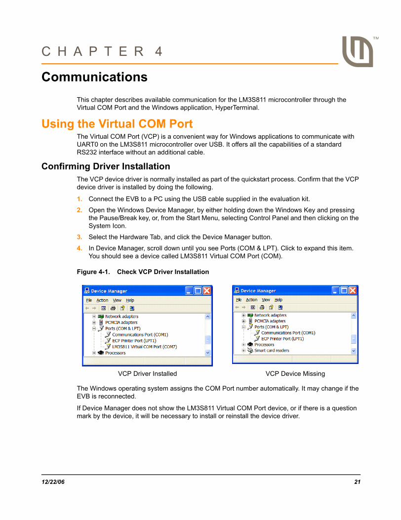
4. In Device Manager, scroll down until you see Ports (COM & LPT). Click to expand this item. You should see a device called LM3S811 Virtual COM Port (COM).
Figure 4-1. Check VCP Driver Installation
The Windows operating system assigns the COM Port number automatically. It may change if the EVB is reconnected.
If Device Manager does not show the LM3S811 Virtual COM Port device, or if there is a question mark by the device, it will be necessary to install or reinstall the device driver.
VCP Driver Installed VCP Device Missing
12/22/06 21

Communications
Installing the VCP Device DriverWhen the EVB is first connected to a USB port, Windows automatically starts a driver installation wizard. The following steps guide you through the installation wizard.
1. Connect the EVB to an available USB port using the USB cable supplied in the kit. In the Found New Hardware Wizard window, select “No, not this time” and click Next.
2. Select “Install from a list or specific location (Advanced)” and click Next.
22 12/22/06
Stellaris® LM3S811 Evaluation Board
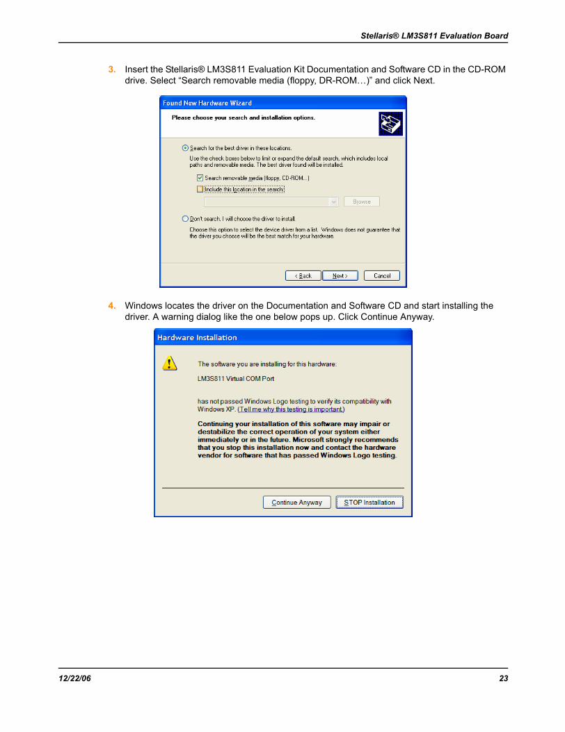
3. Insert the Stellaris® LM3S811 Evaluation Kit Documentation and Software CD in the CD-ROM drive. Select “Search removable media (floppy, DR-ROM…)” and click Next.
4. Windows locates the driver on the Documentation and Software CD and start installing the driver. A warning dialog like the one below pops up. Click Continue Anyway.
12/22/06 23
Communications
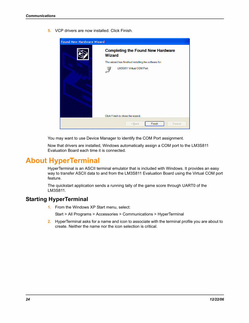
5. VCP drivers are now installed. Click Finish.
You may want to use Device Manager to identify the COM Port assignment.
Now that drivers are installed, Windows automatically assign a COM port to the LM3S811 Evaluation Board each time it is connected.
About HyperTerminalHyperTerminal is an ASCII terminal emulator that is included with Windows. It provides an easy way to transfer ASCII data to and from the LM3S811 Evaluation Board using the Virtual COM port feature.
The quickstart application sends a running tally of the game score through UART0 of the LM3S811.
Starting HyperTerminal1. From the Windows XP Start menu, select:
Start > All Programs > Accessories > Communications > HyperTerminal
2. HyperTerminal asks for a name and icon to associate with the terminal profile you are about to create. Neither the name nor the icon selection is critical.
24 12/22/06
Stellaris® LM3S811 Evaluation Board
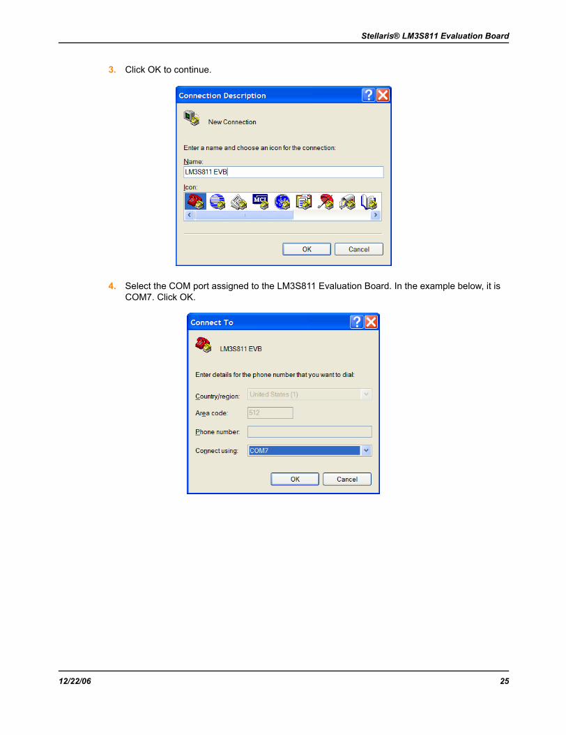
3. Click OK to continue.
4. Select the COM port assigned to the LM3S811 Evaluation Board. In the example below, it is COM7. Click OK.
12/22/06 25

Communications
5. Use the Properties dialog box to set the Port Settings. The quickstart application sends data at 115200 baud, 8 data bits, no parity, 1 stop bit, and no flow-control. Click OK.
6. HyperTerminal now starts. When the quickstart game is played, score data is visible in the terminal window. Save the terminal settings when exiting HyperTerminal.
26 12/22/06

A P P E N D I X A
Contact Information
Company InformationLuminary Micro, Inc. designs, markets, and sells ARM Cortex-M3 based microcontrollers for use in embedded applications within the industrial, commercial, and consumer markets. Luminary Micro is ARM's lead partner in the implementation of the Cortex-M3 core. Please contact us if you are interested in obtaining further information about our company or our products.
Luminary Micro, Inc.108 Wild Basin, Suite 350Austin, TX 78746Main: +1-512-279-8800Fax: +1-512-279-8879http://[email protected]
Support InformationFor support on Luminary Micro products, contact:
[email protected]+1-512-279-8800, ext. 3
December 22, 2006 27

28 December 22, 2006

A P P E N D I X B
SchematicsSchematics for the Stellaris LM3S811 Evaluation Board follow.
December 22, 2006 29

Figure B-1. LM3S811 Microcontroller (sheet 1 of 2)
11
22
33
44
55
66
DD
CC
BB
AA
Docum
en
t N
um
ber:
Rev
Sh
eet
Date
:of
9/3
/2006
12
Dra
win
g T
itle
:
Page T
itle
:
Siz
e
LM
3S
811 E
val
uat
ion B
oar
d
MC
U, P
erip
her
als
and I
/O B
reak
out
B
A2
1
0.1
UF
C10
0.1
UF
C11
0.1
UF
C12
0.1
UF
C13
+3.3
V
0.1
UF
C14
1U
F
C15
LD
O
OS
C0
PB
6/C
0+
R1
10K
+3.3
V
SW
1S
W-P
B
R8
50K
Peri
phe
ral D
evic
es
GN
D
+3.3
V R9
10K
+3.3
V
PA
0/U
0R
xP
A1/U
0T
xP
A2/S
SIC
lkP
A3/S
SIF
ssP
A4/S
SIR
xP
A5/S
SIT
x
PC
4P
C5/C
CP
1P
C6/C
CP
3P
C7/C
CP
4
PE
0/P
WM
4P
E1/P
WM
5
AD
C3
AD
C2
AD
C1
AD
C0
PD
7/C
0O
PD
6/F
ault
PD
5/C
CP
2P
D4/C
CP
0P
D3/U
1T
xP
D2/U
1R
xP
D1/P
WM
1P
D0/P
WM
0
PB
7
PB
0/P
WM
2P
B1/P
WM
3
PB
4/C
0-
PB
5/C
CP
5
PB
3/I
2C
SD
AP
B2/I
2C
SC
L
PA
2/S
SIC
lkP
A3/S
SIF
ssP
A4/S
SIR
xP
A5/S
SIT
x
PD
0/P
WM
0P
D1/P
WM
1
PB
0/P
WM
2P
B1/P
WM
3
PE
0/P
WM
4P
E1/P
WM
5P
B3/I
2C
SD
AP
B2/I
2C
SC
L
PB
7P
B6/C
0+
PB
4/C
0-
PD
6/F
ault
PD
7/C
0O
AD
C0
AD
C1
AD
C2
AD
C3
PB
5/C
CP
5P
C7/C
CP
4
PC
6/C
CP
3P
D5/C
CP
2P
C5/C
CP
1
PC
4P
A0/U
0R
xP
A1/U
0T
x
PD
2/U
1R
xP
D3/U
1T
x
GN
D
GN
DG
ND
GN
D
PD
4/C
CP
0
GN
D
+3.3
VR
ES
ET
n
RE
SE
Tn
AD
C0
PC
4
Thum
bw
hee
l P
ote
nti
om
eter
Use
r P
ush
Butt
on
Sta
tus
LE
DR
10
220
D2
Gre
en
PC
5/C
CP
1
Eval
Res
et S
wit
ch
NC
1
VS
S2
GD
R3
VD
DB
4
FB
5
RE
SE
6
VB
RE
F7
NC
8
NC
9
NC
10
VD
D11
BS
112
BS
213
NC
14
CS
n15
RE
Sn
16
D/C
n17
R/W
n18
E/R
Dn
19
D0
20
D1
21
D2
22
D3
23
D4
24
D5
25
D6
26
D7
27
IRE
F28
VC
OM
H29
VC
C30
N.C
.31
U2
OS
RA
M
GN
D
Q1
BS
S123
R3
10K
R4
1.5
K
1U
FC
3
100uH
L1
+3.3
V 1U
F
C1
+3.3
V
1U
F
C6
R7
620K
GN
DG
ND
GN
D
96x16 O
LE
D
DIS
PL
AY
R2
10
1U
F
C5
JP5
JP6
JP7
JP1
JP2
R5
2.2
KR
62.2
K
+3.3
V+
3.3
V
OL
ED
Volt
age
Boost
Cir
cuit
+9V
PB
2/I
2C
SC
L
PB
3/I
2C
SD
A
I/O
Bre
ako
ut
Hea
ders
Re
mo
ve
JP
1..
7 (
06
03
Re
sis
tors
) to
Revis
ion
Date
Descri
pti
on
0A
ug 2
, 06
Rel
ease
for
Rev
0 P
CB
His
tory
JP3
JP4
PA
0/U
0R
x
PA
1/U
0T
x
TC
K/S
WC
LK
TM
S/S
WD
IOT
DI
TD
O
VC
P_T
X
VC
P_R
X
PA
0/U
0R
x17
PA
1/U
0T
x18
PA
2/S
SIC
lk19
PA
3/S
SIF
ss20
PA
4/S
SIR
x21
PA
5/S
SIT
x22
PC
0/T
CK
/SW
CL
K40
PC
1/T
MS
/SW
DIO
39
PC
2/T
DI
38
PC
3/T
DO
/SW
O37
PC
414
PC
5/C
CP
113
PC
6/C
CP
312
PC
7/C
CP
411
PD
0/P
WM
025
PD
1/P
WM
126
PD
2/U
1R
x27
PD
3/U
1T
x28
PD
4/C
CP
045
PD
5/C
CP
246
PD
6/F
ault
47
PD
748
VD
D7
VD
D15
VD
D23
VD
D32
GN
D8
GN
D16
GN
D24
GN
D31
RS
T5
LD
O6
OS
C0
9
OS
C1
10
PB
0/P
WM
229
PB
1/P
WM
330
PB
2/I
2C
SC
L33
PB
3/I
2C
SD
A34
PB
4/C
0-
44
PB
5/C
CP
543
PB
6/C
0+
42
PB
7/T
RS
T41
PE
0/P
WM
435
PE
1/P
WM
536
AD
C3
4A
DC
23
AD
C1
2A
DC
01
U1
LM
3S
811
US
B_R
ST
n
6M
HZ
_C
LO
CK
12
Y1
6.0
0M
Hz
18P
F
C8
18P
F
C9
fre
e G
PIO
lin
es a
s r
eq
uir
ed
.
D3
CD
0603-S
0180
1U
F
C4
1U
F
C7
SW
2S
W-P
B
EX
TD
BG
EN
n
R30
10K
+3.3
V
40
38
37
36
35
34
33
31
30
29
28
27
26
25
24
23
22
21
32
2 3 4 5 6 7 8 910
11
12
13
14
15
16
17
18
19
20
39
Pin
1 i
s O
mit
ted
R31
4.7
K
1
AA
ug 1
8, 06
Rel
ease
for
Rev
A P
CB
+3.3
VR
ES
ET
n
GN
D
for P
ola
riz
ati
on
LE
DP
WR
IN
R32
10
R33
10
A1
Aug 2
1, 06
D5,D
6 f
unct
ion r
edundan
t -
chan
ge
to r
esis
tors
. C
han
ge
R2 t
o 1
0 o
hm
s.
A2
Aug 3
0, 06
Add C
17 (
0.1
uF
) to
res
et c
ircu
it.
0.1
UF
C17
OS
096016P
P08M
G1B
10
OS
096016P
P08M
O1B
10
OS
096016P
P08M
Y0B
10
30 December 22, 2006
Stellaris® LM3S811 Evaluation Board
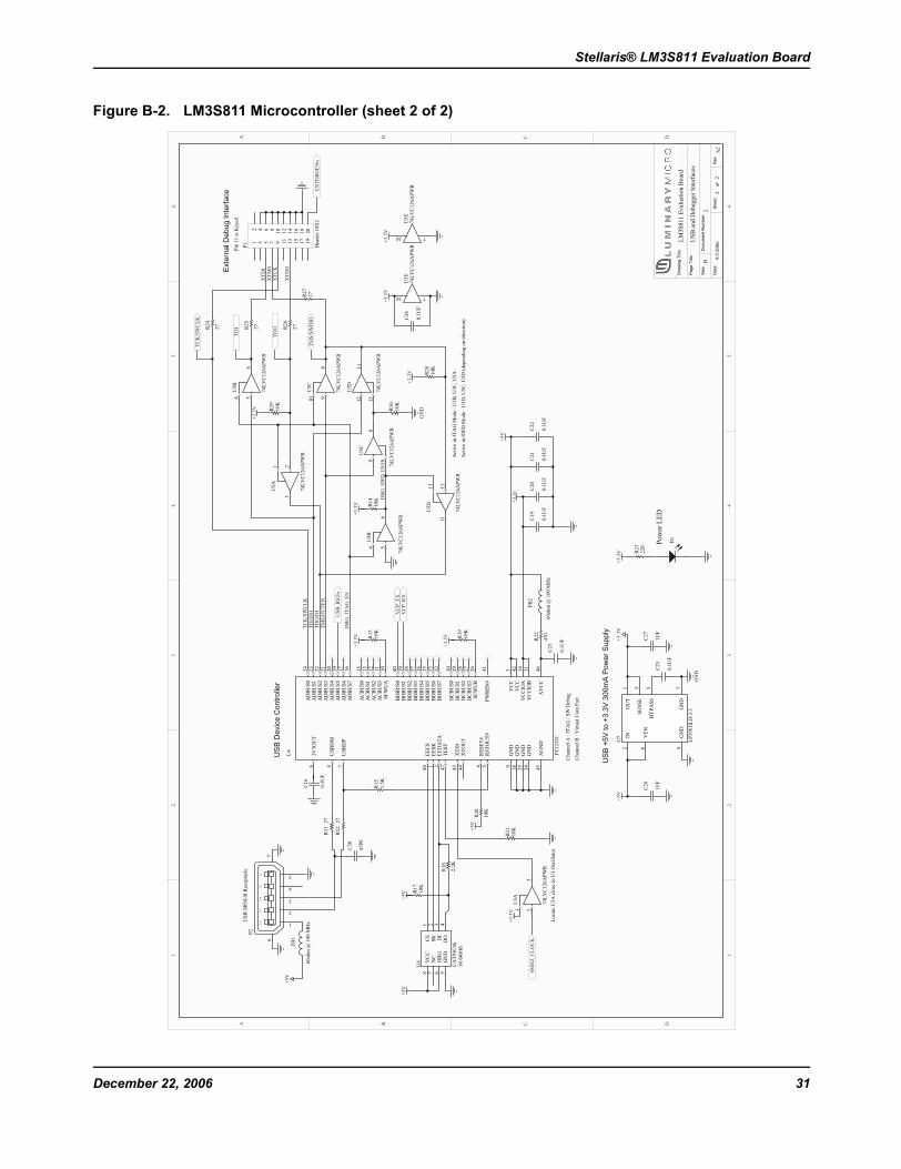
Figure B-2. LM3S811 Microcontroller (sheet 2 of 2)
11
22
33
44
55
66
DD
CC
BB
AA
Docum
en
t N
um
ber:
Rev
Sh
eet
Date
:of
9/3
/2006
22
Dra
win
g T
itle
:
Page T
itle
:
Siz
e
LM
3S
811 E
val
uat
ion B
oar
d
US
B a
nd D
ebugger
Inte
rfac
es
B
A2
2
FB
1
60ohm
@ 1
00 M
Hz
FB
2
60ohm
@ 1
00 M
Hz
GN
D18
GN
D25
GN
D34
AD
BU
S0
24
AD
BU
S1
23
AD
BU
S2
22
AD
BU
S3
21
AD
BU
S4
20
AD
BU
S5
19
AD
BU
S6
17
AD
BU
S7
16
AC
BU
S0
15
AC
BU
S1
13
AC
BU
S2
12
AC
BU
S3
11
BD
BU
S0
40
BD
BU
S1
39
BD
BU
S2
38
BD
BU
S3
37
BD
BU
S4
36
BD
BU
S5
35
BD
BU
S6
33
BD
BU
S7
32
BC
BU
S0
30
BC
BU
S1
29
BC
BU
S2
28
BC
BU
S3
27
SI/
WU
A10
SI/
WU
B26
GN
D9
AG
ND
45
VC
C3
VC
C42
VC
CIO
A14
VC
CIO
B31
AV
CC
46
PW
RE
N#
41
XT
OU
T44
XT
IN43
EE
CS
48
EE
SK
1
EE
DA
TA
2
TE
ST
47
RE
SE
T#
4
RS
TO
UT
#5
3V
3O
UT
6
US
BD
M8
US
BD
P7
U4
FT
2232C
+3.3
v
+5V
R11
27
R12
27
12
34
56
78
910
11
12
13
14
15
16
17
18
19
20
P1
Hea
der
10X
2
DB
G_S
WD
_E
N
R13
10K
R19
10K
+3.3
V
+3.3
V
R16
10K
DB
G_JT
AG
_E
N
R14
10K
R17
10K
R18
2.2
K
R15
1.5
K
R21
10K
R20
10K
R22
470
+5V
+5V
+5V
+5V
XT
DI
XT
MS
TC
K/S
WC
LK
TD
I/D
OT
DO
/DI
TM
S/O
UT
EN
1U
F
C26
1U
F
C27
+3.3
V+
5V
0.1
UF
C23
0.1
UF
C19
0.1
UF
C20
0.1
UF
C21
0.1
UF
C22
0.1
UF
C16
+3.3
V R23
220
D1
Pow
er L
ED
US
B D
evic
e C
ontr
olle
r
Chan
nel
A :
JT
AG
/ S
W D
ebug
Chan
nel
B :
Vir
tual
Com
Port
US
B +
5V
to +
3.3
V 3
00m
A P
ow
er
Supply
Exte
rnal D
eb
ug In
terf
ace
R26
27
R24
27
R25
27
XT
CK
XT
DO
R27
27
21
3
U3A
74L
VC
126A
PW
R
54
6
U3B
74L
VC
126A
PW
R
9
10
8
U3C
74L
VC
126A
PW
R
12
13
11
U3D
74L
VC
126A
PW
R
714
U5E
74L
VC
126A
PW
R
21
3
U5A
74L
VC
126A
PW
R
54
6
U5B
74L
VC
126A
PW
R
9
10
8
U5C
74L
VC
126A
PW
R
714
U3E
74L
VC
126A
PW
R
12
13
11
U5D
74L
VC
126A
PW
R
+3.3
V+
3.3
V
0.1
UF
C24
VC
P_T
XV
CP
_R
X
TC
K/S
WC
LK
TD
I
TD
O
TM
S/S
WD
IO
Act
ive
in J
TA
G M
ode
: U
3B
, U
3C
, U
5A
Act
ive
in S
WD
Mode
: U
3D
, U
5C
, U
5D
(dep
endin
g o
n d
irec
tion)
US
B_R
ST
n
C30
47P
F+
3.3
V
GN
D
+3.3
V
6M
HZ
_C
LO
CK
Loca
te U
3A
clo
se t
o U
1 O
scil
lato
r
R28
10K
+3.3
V
R29
10K
+3.3
V
Pin
11 i
s K
eyed
5V
D-
D+
ID
G
1
2
3
4
7
5
6
P2
US
B M
INI-
B R
ecep
tacl
e
OU
T1
SE
NS
E3
VE
N6
GN
D4
BY
PA
SS
5
GN
D7
IN2
U7
LP
3981IL
D-3
.3
0.1
UF
C25
GN
D
EX
TD
BG
EN
n
CS
1
SK
2
DI
3
DO
4G
ND
5O
RG
6N
C7
VC
C8
1K
64X
16
U6
CA
T93C
46
December 22, 2006 31

32 December 22, 2006
A P P E N D I X C
Connection DetailsThis appendix contains the following sections:
Component Locations
Evaluation Board Dimensions
I/O Breakout Pads and Recommended Connectors
ARM Target Pinout
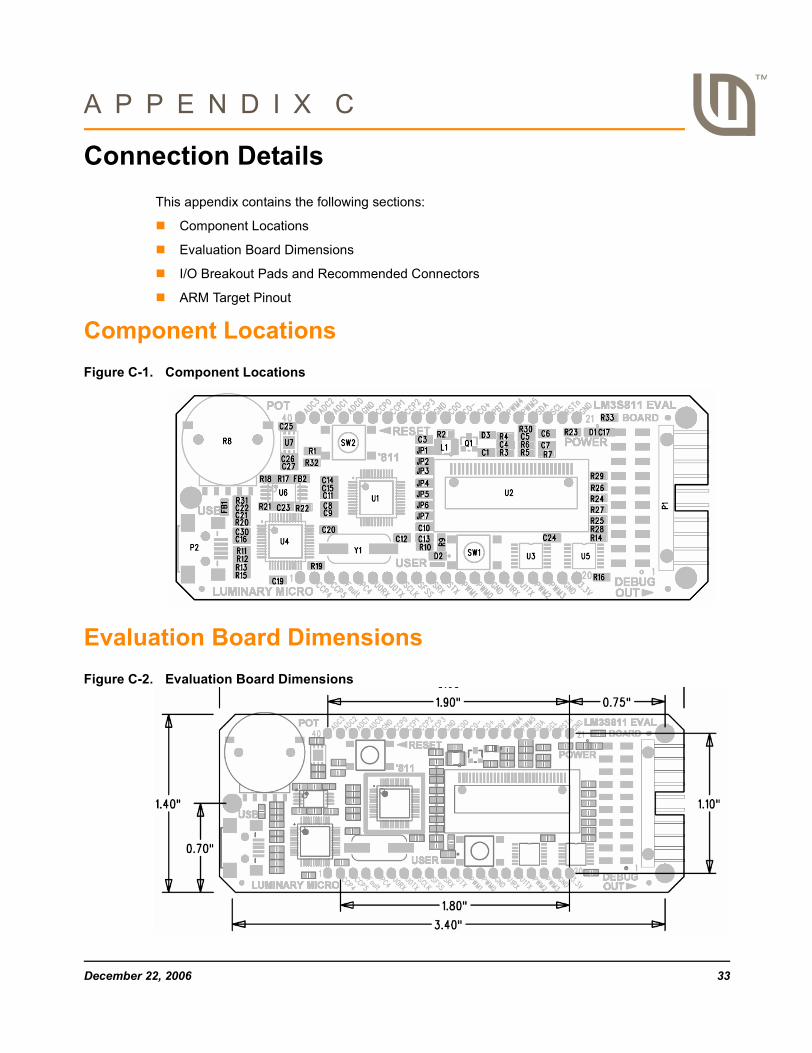
Component LocationsFigure C-1. Component Locations
Evaluation Board DimensionsFigure C-2. Evaluation Board Dimensions
December 22, 2006 33

I/O Breakout Pads and Recommended ConnectorsThe LM3S811 EVB has 32 I/O pads, 6 power pads, and a reset signal, for a total of 39 pads. Connection can be made by soldering wires directly to these pads, or by using 0.1” pitch headers and sockets.
Table C-1. I/O Breakout Pads
Pad No. Description Pad No. Description
1 BLANK 40 ADC3
2 PC7/CCP4 39 ADC2
3 PB5/CCP5 38 ADC1
4 PD6/Fault 37 ADC0a
a. Indicates an I/O line that is used by EVB hardware.
5 PC4a 36 GND
6 PA0/U0Rxa 35 PD4/CCP0
7 PA1/U0Txa 34 PC5/CCP1
8 PA2/SSIClk 33 PD5/CCP2
9 PA3/SSIFss 32 PC6/CCP3
10 PA4/SSIRx 31 GND
11 PA5/SSITx 30 PD7/C0O
12 PD1/PWM1 29 PB4/C0-
13 PD0/PWM0 28 PB6/C0+
14 GND 27 PB7b
b. PB7 should not be used as a GPIO.
15 PD2/U1Rx 26 PE0/PWM4
16 PD3/U1Tx 25 PE1/PWM5
17 PB0/PWM2 24 PB3/I2CSDAa
18 PB1/PWM3 23 PB2/I2CSCLa
19 GND 22 RESET
20 +3.3V 21 GND
Table C-2. Recommended Connectors
Pins 2-20 (19 way) Socket Sullins PPPC191LFBN-RC Digikey S7052-ND
Pin Header Sullins PTC19SAAN Digikey S1012-19-ND
Pins 21-40 (20 way) Socket Sullins PPPC201LFBN-RC Digikey S7053-ND
Pin Header Sullins PTC20SAAN Digikey S1012-20-ND
34 December 22, 2006
Stellaris® LM3S811 Evaluation Board
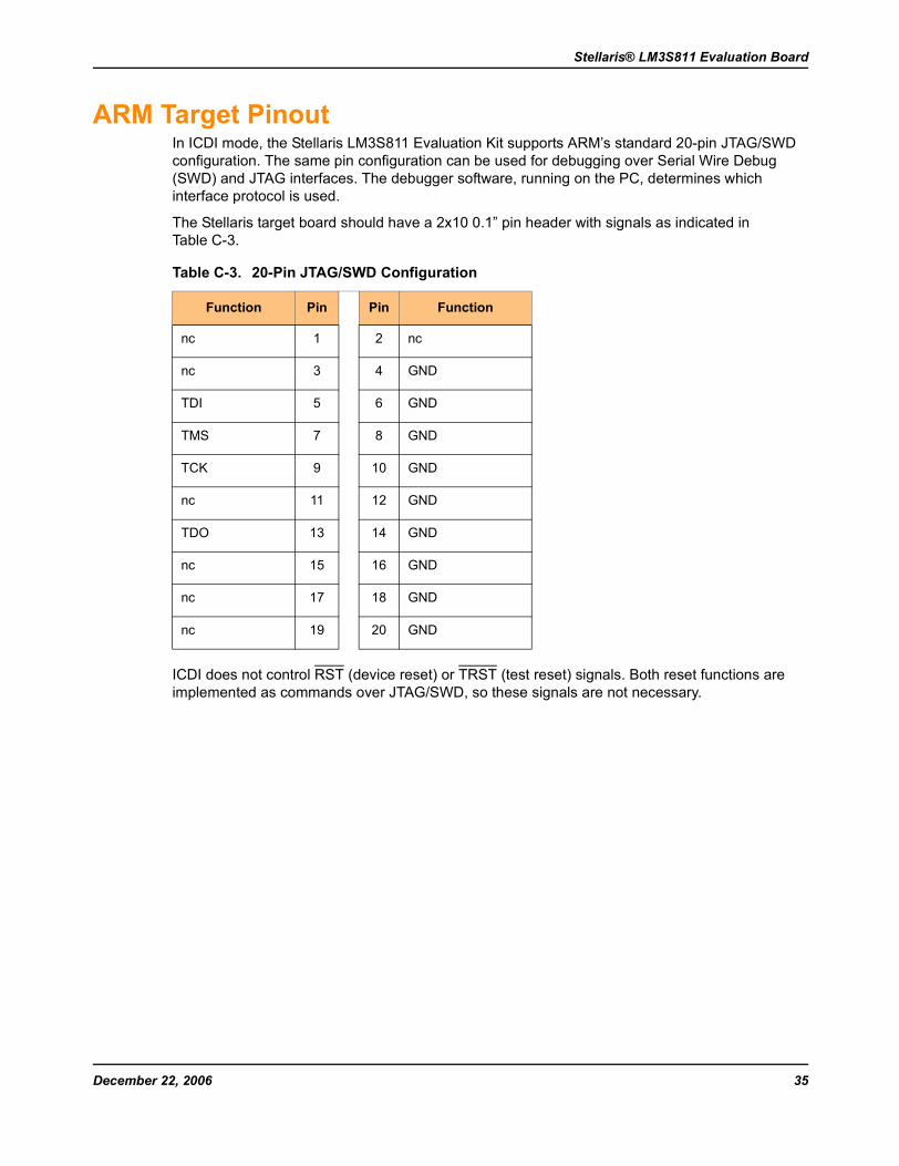
ARM Target PinoutIn ICDI mode, the Stellaris LM3S811 Evaluation Kit supports ARM’s standard 20-pin JTAG/SWD configuration. The same pin configuration can be used for debugging over Serial Wire Debug (SWD) and JTAG interfaces. The debugger software, running on the PC, determines which interface protocol is used.
The Stellaris target board should have a 2x10 0.1” pin header with signals as indicated in Table C-3.
ICDI does not control RST (device reset) or TRST (test reset) signals. Both reset functions are implemented as commands over JTAG/SWD, so these signals are not necessary.
Table C-3. 20-Pin JTAG/SWD Configuration
Function Pin Pin Function
nc 1 2 nc
nc 3 4 GND
TDI 5 6 GND
TMS 7 8 GND
TCK 9 10 GND
nc 11 12 GND
TDO 13 14 GND
nc 15 16 GND
nc 17 18 GND
nc 19 20 GND
December 22, 2006 35

36 December 22, 2006