Embed Size (px)
Citation preview

STENNICATOR PUMPINSTALLATION AND MAINTENANCE MANUAL
PERISTALTIC METERING PUMPS SINCE 1957

2 www.stenner.comStennicator
Warranty and Customer Service............................................................ 3
Safety Information ........................................... 4-6, 11-13, 16-20, 22-25
Materials of Construction .................................................................... 7
Accessory Checklist ............................................................................. 8
Output................................................................................................. 9
Operation & Installation................................................................ 10-19
Troubleshooting ............................................................................ 20-22
Tube Replacement ........................................................................ 23-26
Exploded View and Parts ............................................................... 27-28
Mounting Template ............................................................................ 29
IMST 0114
TABLE OF CONTENTS

LIMITED WARRANTYStenner Pump Company will for a period of one (1) year from the date of purchase (proofof purchase required) repair or replace – at our option – all defective parts. Stenner is notresponsible for any removal or installation costs. Pump tube assemblies and rubbercomponents are considered perishable and are not covered in this warranty. Pump tubewill be replaced each time a pump is in for service, unless otherwise specified. The cost ofthe pump tube replacement will be the responsibility of the customer. Stenner will incurshipping costs for warranty products shipped from our factory in Jacksonville, Florida. Anytampering with major components, chemical damage, faulty wiring, weather conditions,water damage, power surges, or products not used with reasonable care and maintained inaccordance with the instructions will void the warranty. Stenner limits its liability solely tothe cost of the original product. We make no other warranty expressed or implied.
RETURNS
Stenner offers a 30-day return policy on factory direct purchases. Except as otherwiseprovided, no merchandise will be accepted for return after 30 days from purchase. Toreturn merchandise at any time, call Stenner at 800.683.2378 for a Return MerchandiseAuthorization (RMA) number. A 15% re-stocking fee will be applied. Include a copy of yourinvoice or packing slip with your return.
DAMAGED OR LOST SHIPMENTSCheck your order immediately upon arrival. All damage must be noted on the deliveryreceipt. Call Stenner Customer Service at 800.683.2378 for all shortages and damageswithin seven (7) days of receipt.
SERVICE & REPAIRSBefore returning a pump for warranty or repair, remove chemical from pump tube byrunning water through the tube, and then run the pump dry. Following expiration of thewarranty period, Stenner Pump Company will clean and overhaul any Stenner meteringpump for a minimum labor charge plus necessary replacement parts and shipping. Allmetering pumps received for overhaul will be restored to their original condition. Thecustomer will be charged for missing parts unless specific instructions are given. To returnmerchandise for repair, call Stenner at 800.683.2378 or 904.641.1666 for a ReturnMerchandise Authorization (RMA) number.
DISCLAIMERThe information contained in this manual is not intended for specific application purposes.Stenner Pump Company reserves the right to make changes to prices, products, andspecifications at any time without prior notice.
3USA and Canada 800.683.2378, International 904.641.1666 Stennicator
WARRANTY AND CUSTOMER SERVICE

4 www.stenner.comStennicator
IMPORTANT SAFETY INSTRUCTIONS
When installing and using this electrical equipment,basic safety precautions should always be followed,including the following:
1.READ AND FOLLOW ALL INSTRUCTIONS.
2.WARNING - To reduce the risk of injury, do not permit children to use this product unless they are closely supervised at all times.
3.WARNING - Risk of Electric Shock. Connect only to a branch circuit protected by a ground-fault circuit interrupter (GFCI). Contact a qualified electrician if you cannot verify that the receptacle is protected by a GFCI.
4.WARNING - To reduce the risk of electric shock, replace damaged cord immediately.
5.SAVE THESE INSTRUCTIONS.

5USA and Canada 800.683.2378, International 904.641.1666 Stennicator
SAFETY INFORMATION
Warns about hazards that CAN cause death, serious personalinjury, or property damage if ignored.
ELECTRIC SHOCK HAZARD
ELECTRIC SHOCK HAZARDPump supplied with grounding power cord and attached plug. To reduce risk ofelectrical shock, connect only to a properly grounded, grounding type receptacle.Install only on a circuit protected by a Ground-Fault Circuit-Interrupter (GFCI). Forlocations other than US and Canada, pump must be supplied through a residualcurrent device (RCD) with a rated residual operating current < 30mA.
DANGER DE CHOC ÉLECTRIQUELa pompe est dotée d’un cordon d’alimentation avec mise à la terre muni d'une fiche.Pour réduire le risque de choc électrique, branchez uniquement sur une prisecorrectement mise à la terre. Installez uniquement sur un circuit protégé par undisjoncteur différentiel. En dehors des États-Unis et du Canada, la pompe doit êtrealimentée par un dispositif à courant différentiel résiduel (RCD) fonctionnant à <30mA.
DO NOT alter the power cord or plug end.DO NOT use receptacle adapters.DO NOT use pump with a damaged or altered power cord or plug end. Contact thefactory or an authorized service facility for repair.
HAZARDOUS VOLTAGEDISCONNECT power cord before removing motor cover for service. Electrical serviceby trained personnel only.
EXPLOSION HAZARDThis pump is not explosion proof. DO NOT install or operate in an explosive environment.
RISK OF EXPOSURE Potential for burns, fire, explosion, personal injury, or property damage. To reduce riskof exposure, the use of proper personal protective equipment is mandatory.
RISK OF FIRE HAZARDDO NOT install or operate on any flammable surface.
RISK OF CHEMICAL OVERDOSETo reduce risk, follow proper installation methods and recommendations. Check yourlocal codes for additional guidelines.
This appliance is not intended for use by persons (includingchildren) with reduced physical, sensory or mental capabilities, or lack of experienceand knowledge, unless they have been given supervision or instruction to concerninguse of the appliance by a person responsible for their safety.

6 www.stenner.comStennicator
SAFETY INFORMATION continued
Warns about hazards that WILL or CAN cause minor personal injury or property damage if ignored.
PLUMBING Metering pump installation must always adhere to your local plumbing codes andrequirements. Be sure installation does not constitute a cross connection. Checklocal plumbing codes for guidelines.
NOTICE: Indicates special instructions or general mandatory action.
This metering pump is portable and designed to be removable from the plumbingsystem without damage to the connections.
Before installing or servicing the pump, read the pump manual for all safetyinformation and complete instructions. The pump is designed for installation andservice by properly trained personnel.
Installation and product must adhere to all regulatory and compliance codesapplicable to the area.
This is the safety alert symbol. When displayed in this manual or on theequipment, look for one of the following signal words alerting you to thepotential for personal injury or property damage.
Acceptable for indoor and outdoor use.
Acceptable pour une utilisation aussi bien à l’intérieur qu’à l’extérieur.
Electrical installation should adhere to all national and local codes. Consult a licensedprofessional for assistance with proper electrical installation.
Removing power from pool/spa recirculation pump must also remove power from pump.
The use of an auxiliary safety device (not supplied), such as a flow switch or sensor,is recommended to prevent feed pump operation in the event of a recirculationpump failure or if flow is not sensed.
Point of injection should be beyond all pumps, filters, and heaters.
Maximum liquid temperature = 40°C.

7USA and Canada 800.683.2378, International 904.641.1666 Stennicator
MATERIALS OF CONSTRUCTION
All HousingsPolycarbonate
Peristaltic Tube* & Check Valve DuckbillSantoprene®, FDA approved
Suction/Discharge Tubing & FerrulesPolyethylene, FDA approved
Weighted Suction Line StrainerPolypropylene or Type 1 Rigid PVC body with Type 1 Rigid PVC cap, NSF listed; ceramic weight
Tube Fittings & Check Valve FittingsType 1 Rigid PVC, NSF listed
Connecting NutsType 1 Rigid PVC or Polypropylene
All FastenersStainless Steel
* Santoprene® is a registered trademark of Exxon Mobil Corporation.

8 www.stenner.comStennicator
ACCESSORY CHECKLIST
Contents
3 Connecting Nuts 1/4" or 6 mm Europe
3 Ferrules 1/4"
1 Injection Check Valve
1 Weighted Suction Line Strainer 1/4"
1 20' Roll of Suction/Discharge Tubing 1/4" White or UV Black OR 6 mm White Europe
1 Additional Pump Tube
1 Installation Manual

9USA and Canada 800.683.2378, International 904.641.1666 Stennicator
Item Number Pump Roller Ounce Pressure Milliliters PressurePrefix Tube Assembly
Turndown Ratioper Min. psi per Min. bar
E20MH H Black N/A 2.7 80 74 5.5
Approximate Output @ 50/60Hz
OUTPUT
NOTICE: The information within this chart is solely intended for use as a guide. The output data is an approximation based onpumping water under a controlled testing environment. Many variables can affect the output of the pump. Stenner PumpCompany recommends that all metering pumps undergo field calibration by means of analytical testing to confirm their outputs.
Setting Run Time* in secondsSimplex Duplex
PRIME 60 60
1 PPG 22 11
1 PPL 6 3
10 PPG 2 1
* Times are approximate (in seconds).
KeyPPG pulse per gallon**
PPL pulse per liter**10 PPG is often referred to as 0.1 US gallons per pulse

10 www.stenner.comStennicator
OPERATION
The Stennicator requires a signal from a water meter providing a dry contact at a setting of1PPG, 10 PPG or 1 PPL. It will proportionally dose at a ratio of 1:128 (1 oz. per gallon) totreat process flow rates up to 2.7 gpm*. At any point, the potentiometer can be turned tothe proper contacting rate setting (1 PPG, 10 PPG, or 1 PPL) to begin dosing proportionallyat the rate of 1:128.
The pump incorporates a signal repeater relay, which will repeat the incoming signal toanother Stennicator, device, or controller.
Turning the potentiometer to PRIME initiates a 60 second cycle to prime the pump. THEPRIME CYCLE HAS A 5 SECOND DELAY. At the end of the PRIME cycle, the pump will stopand will remain stopped until it is set to a contacting rate.
Turning the potentiometer to STANDBY, stops the pump and resets the PRIME cycle. To runanother PRIME cycle, set to STANDBY, then turn the potentiometer to PRIME. When thepump is placed in STANDBY, it will not dose when it receives a signal from the water meter,but it will still repeat the incoming signal.
The installation can be duplexed by using two Stennicator pumps to keep pace at higherflow rates. By properly wiring the signal cables (details in the installation section) eachpump will deliver at a ratio of 1:256 (0.5 oz. per gallon) to achieve a ratio of 1:128 (1 oz.per gallon). This will allow a ratio of 1:128 up to flows of 5.4 gallons per minute.
* At flow rates above 2.7 gpm the pump will run during its cycle and miss the next meter dry contact. It willrestart when it receives the next dry contact.
11USA and Canada 800.683.2378, International 904.641.1666 Stennicator
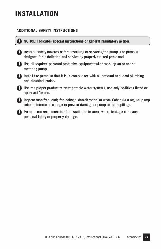
INSTALLATION
ADDITIONAL SAFETY INSTRUCTIONS
NOTICE: Indicates special instructions or general mandatory action.
Read all safety hazards before installing or servicing the pump. The pump isdesigned for installation and service by properly trained personnel.
Use all required personal protective equipment when working on or near ametering pump.
Install the pump so that it is in compliance with all national and local plumbingand electrical codes.
Use the proper product to treat potable water systems, use only additives listed orapproved for use.
Inspect tube frequently for leakage, deterioration, or wear. Schedule a regular pumptube maintenance change to prevent damage to pump and/or spillage.
Pump is not recommended for installation in areas where leakage can causepersonal injury or property damage.
12 www.stenner.comStennicator
INSTALLATION continued
MOUNT PUMP
Select a dry location (to avoid water intrusion and pump damage) above thesolution tank.
To prevent pump damage in the event of a pump tube leak, never mount thepump vertically with the pump head up.
DO NOT mount pump directly over an open solution tank. Keep tank covered.
Avoid flooded suction or pump mounted lower than the solution container. Drawsolution from the top of the tank. Pump can run dry without damage. If pump isinstalled with a flooded suction, a shut-off valve or other device must be providedto stop flow to pump during service.
To prevent motor damage, verify with a volt meter that the receptacle voltagecorresponds with the pump voltage.
1. Connect the wires
Simplex Installationa. Connect the BLACK & RED wires from the pump to the dry contact input from
the water meter.b. Connect the GREEN & WHITE wires from the pump to another device that
accepts a dry contact input as desired or required by the application.
Duplex Installation
a. Connect BROWN (or ORANGE) & BLUE wires together in Pump #1.b. Connect BROWN (or ORANGE) & BLUE wires together in Pump #2.NOTE: The BROWN (or ORANGE) & BLUE wires are connected to allow for the pumpsto run at half of the standard cycle time. This allows the signal output, from the firstpump, to be provided to a second Stennicator to allow treatment of up to 5.4 GPM of process flow. DO NOT connect the BROWN (or ORANGE) & BLUE wires from onepump to another.c. Connect GREEN & WHITE wires of Pump #1 to BLACK & RED wires of Pump #2.
d. Connect BLACK & RED of Pump #1 to the dry contact input from the water meter.
e. Connect the GREEN & WHITE wires from Pump #2 to another device thataccepts a dry contact input as desired or required by the application.
2. Set the potentiometer to STBY.3. Plug the power supply into a receptacle.
NOTE: The repeater relay is rated for a maximum signal level of 36VDC @ 25mA.

13USA and Canada 800.683.2378, International 904.641.1666 Stennicator
INSTALLATION continued
ADDITIONAL INSTRUCTIONS FOR CE PUMPSADDITIONAL INSTALLATION INSTRUCTIONS1. All Class II Pumps located in Zone 1 of swimming pool areas require locating where flooding cannot occur.
2. This pump is intended to be installed as “fixed” as opposed to portable.
3. The pump must be installed in a vertical position as shown in the installation diagram.
4. After installation, the power supply plug must be accessible during use.
5. This unit must be scrapped if the supply cord is damaged.
6. Observe and comply with all National Wiring Standards.
ZUSTAZLICHE INSTALLIERUNGSANWEISUNGUN1. Pumpen die sich in Zone 1 vom Schwimmbecken befinden sollen sind so einzurichten daß
Ueberschwemmungen nicht vorkommen werde.
2. Diese Pumpe ist als fest montierte Ausrustung bedacht und soll nicht umstellbar gebraucht werden.
3. Die Pumpe muss vertikal installiert werden, siehe Zeichnung.
4. Die Stromversorgung muss nach der Installierung noch zuganglich sein.
5. Bei beschadigter Verkabelung ist dieses Gerat nicht mehr zu gebrauchen.
6. Staatliche Vernetzungsvorchriften mussen eingehalten werden.
INSTRUCTIONS SUPPLÉMENTAIRES D’INSTALLTION1. Toutes les pompes installées dans la Zone 1 du périmètre de la piscine doivent être situées de manière à
ne pas pouvoir être inondées.
2. Cette pompe est prévue pour installation fixe et non pas portative.
3. La pompe doit être installée en position verticale selon le dessin.
4. Après l’installation, la prise électrique doit rester accessible pendant l’utilisation.
5. Cette unité doit être mise au rebut si le cordon électrique est endommagé.
6. Observez et adhérez à toutes les Normes Nationales pour Installations Electriques.
INSTRUCCIONES ADICIONALES PARA INSTALACION1. Todas las bombas Clase II situadas en la Zona 1 de las áreas de la piscina requieren colocarse donde no
puedan ser inundadas.
2. Esta bomba es para ser instalada “fija” en vez de portátil.
3. La bomba debe ser instalada en posición vertical como se muestra en el diagrama de instalación.
4. Depués de la instalación el enchufe suministrador de energía debe estar accesible durante el uso.
5. Se deberá deshechar la unidad si el cordón de abastecimiento se deteriora.
6. Observe y cumpla con todas las Reglas Nacionales para Instalaciones Eléctricas.
ISTRUZIONI SUPPLEMENTARI PER L’ INSTALLAZIONE1. Tutte le pompe Classe II localizzate nella Zona 1 della superficie circostante la piscina devono essere
collocate dove gli allagamenti no possono accadere.
2. Questa pompa, é inteso, deve essere installata come ‘fissa’ e non come portatile.
3. La pompa deve essere installata in posizione verticale come mostrato sul disegno.
4. Dopo l’installazione, la spina deve essere accessibile durante l’uso.
5. Questa unitá deve essere gettata via se il filo elettrico é danneggiato.
6. Osservare e aderire a tutte le Norme Nazionali Sugli Impianti Elettrici.

Direction of water flowDisassembled viewof nut and ferrule
Water Meter
Water MeterOutput Cable
Pump InputSignal Cables
Grounded Power Outlet:(Grounded-Fault Circuit-Interrupter GFCI)
Suction Line
Discharge Line
InjectionCheck Valve
Shut-Off Valve
Duckbill
Disassembled View ofInjection Check Valve
Up to 80 psi
Flowdirectionof solution
Power Cord
14 www.stenner.comStennicator
INSTALLATION DIAGRAM – SIMPLEX
Solution Tank
Black
Red
WhiteGreen
RepeaterRelay
Blue Brown (or Orange)
WaterMeter
Connectfor DuplexOperation

InjectionCheck Valve
Shut-OffValve
Direction of water flow
Water Meter
Disassembledview of nutand ferrule
Power Cord
Grounded Power Outlet:(Grounded-Fault Circuit-Interrupter GFCI)
Pump InputSignal Cables
Water MeterOutput Cable
Discharge Line
Duckbill
Disassembled View ofInjection Check Valve
Up to 80 psi
Flowdirectionof solution
Solution Tank
Pump #1 Pump #2
Suction Line
15USA and Canada 800.683.2378, International 904.641.1666 Stennicator
INSTALLATION DIAGRAM – DUPLEX
Pump #1
Pump #2
Brown
(or Orange)
Blue
Black
Red
Green
Red
Green
White
Blue
Brown
(or Orange)
WhiteBlack
To Controller
To WaterMeter

16 www.stenner.comStennicator
INSTALLATION continued
Suction Line
INSTALL SUCTION LINE TO PUMP HEAD
1. Uncoil the suction/discharge line. Use outside of solution tank as a guide to cutproper length of suction line ensuring it will be 2-3" above the bottom of solution tank.
Allow sufficient slack to avoid kinks and stress cracks. Always make a cleansquare cut to assure that the suction line is burr free. Normal maintenancerequires trimming.
Suction lines that extend to the bottom of the tank can result in debris pickupleading to clogged injectors and possible tube failure.
2. Make connections by sliding the line(s) through connecting nut and ferrule and fingertighten to the corresponding tube fittings.
3. Finger tighten nut to the threaded tube fitting while holding the tube fitting.
Over tightening the ferrule and nut with a wrench may result in damaged fittings,crushed ferrules, and air pick up.
DO NOT use thread sealant tape on pump tube connections or tools to tighten connections.
DO NOT use pliers.
Note: Beveled ends of ferrulesface pump. Tubing shouldbottom into all fittings.
Finger tightennut
Discharge Line
Ferrules
DO NOT use Teflon tapeon pump tube threads.

17USA and Canada 800.683.2378, International 904.641.1666 Stennicator
INSTALLATION continued
INSTALL SUCTION WEIGHT TO SUCTION LINE
1. Drill a hole into the bung cap or solution tank lid. Slide the tubing through andsecure the weighted strainer to the line.
2. To attach the strainer, push approximately 3.5" of suction line through the cap on thestrainer body. Pull tubing to make sure it is secure.
3. Suspend slightly above tank bottom to reduce the chance of sediment pickup.
DO NOT mix additives in the solution container. Follow recommended mixingprocedures according to the manufacturer.
DO NOT operate pump unless additive is completely in solution. Turn pump offwhen replenishing solution.
3"
Suction Line
3.5"(9 cm)
WeightedSuction LineStrainer

18 www.stenner.comStennicator
INSTALLATION continued
INSTALL DISCHARGE LINE TO PUMP HEAD AND INJECTION POINT
1. Make a secure finger tight connection on the discharge fitting of the pump head asinstructed in Install Suction Line instructions.
DO NOT use thread sealant tape on pump tube connections or tools to tighten connections.
HAZARDOUS PRESSURE: Shut off water or circulation systemand bleed off any system pressure.
Locate a point of injection beyond all pumps and filters or as determined by the application.
2. A 1/4" or 1/2" Female NPT (FNPT) connection is required for installing the injectionfitting. If there is no FNPT fitting available, provide one by either tapping the pipe orinstalling FNPT pipe tee fitting.
3. Wrap the Male NPT (MNPT) end of injection fitting with 2 or 3 turns of threading tape.If necessary, trim the injection fitting quill as required to inject product directly intoflow of water.
Trim injection fitting end
DO NOT use Teflontape on pump tube threads.
DO NOT use pliers. InjectionCheck Valve
Shut-Off Valve
1/4" or 1/2" FNPTReductionBushing
Typical Point of Injection

19USA and Canada 800.683.2378, International 904.641.1666 Stennicator
INSTALLATION continued
4. Hand tighten the injection fitting into the FNPT fitting.
a. Install connecting nut and ferrule to the pump discharge tubing. Insert dischargetubing into injection fitting until it reaches base of fitting.
b. Finger tighten connecting nut to fitting.
5. Turn pump on and re-pressurize system. Observe flow as actuated by system andcheck all connections for leaks.
6. After suitable amount of dosing time, perform tests for desired readings (e.g., pH orppm). If necessary, fine tune dosing levels by rotating potentiometer or by adjustingsolution strength.
The injection point and fitting require periodic maintenance to clean anydeposits or buildup. To allow quick access to the point of injection, Stennerrecommends the installation of shut-off valves.

20 www.stenner.comStennicator
TROUBLESHOOTING – DRIVE ASSEMBLY
HAZARDOUS VOLTAGEDISCONNECT power before service. Electrical service should be performed by trainedpersonnel only.
PROBLEM POSSIBLE CAUSE SOLUTION
Noise is excessively loud Lubrication is insufficient Grease gears and gear posts
Gears or gear posts are worn Inspect/replace gears and gear posts
Drive assembly does not work Electrical supply is faulty Check supply voltage circuit
DC motor is damaged Replace drive assembly
Power cord is damaged Replace drive assembly
Drive assembly runs; Worn or damaged gears Replace gears as neededoutput shaft does not
Phenolic gear is stripping Gear posts worn Replace gear posts and phenolic gear
Rusted helical gear Buff off helical gear and replace phenolic gear
Insufficient lubrication Replace phenolic gear and lubricate with AquaShield®
Output shaft does not turn Worn or damaged roller assembly Replace roller assembly
Worn or damaged gears Replace gears as needed
Damaged circuit board Replace drive assembly

21USA and Canada 800.683.2378, International 904.641.1666 Stennicator
TROUBLESHOOTING – PUMP HEAD
PROBLEM POSSIBLE CAUSE SOLUTION
Components are cracking Incompatibility with fluid Check compatibility
Visible fluid in pump head Pump tube rupture/leak Replace pump tube and ferrules
No pump output; Depleted solution tank Replenish solutionpump head rotates Pump suction line weight is above solution Maintain suction line 2-3" off bottom of tank
Suction line leak Inspect or replace suction line
Ferrules installed incorrectly or damaged Replace compression ferrules
Injection point is clogged Inspect and clean injection point
Clogged suction/discharge tubing Clean and/or replace as necessary
Life of pump tube is exhausted Replace pump tube
Suction tubing is flush with the nose Pull suction tubing approximately 1" fromof the weighted strainer bottom of strainer; cut bottom of suction
tubing at an angle
Pump cover not secured properly Ensure that pump cover is properly latched
Low pump output; Pump tube is worn Replace pump tubepump head rotates Rollers worn or broken Install new roller assembly
Injection point is restricted Inspect and clean injection point
Incorrect tube size Replace tube with correct size
High system back pressure Confirm system pressure does not exceed 80 psi (5.5 bar)
Pump cover not secured properly Ensure that pump cover is properly latched
Potentiometer set incorrectly Adjust potentiometer
No pump output; Roller assembly is stripped Replace roller assemblypump head doesn’t rotate Faulty board Replace drive assembly
Drive assembly problem Refer to Troubleshooting – Drive Assembly
Potentiometer set incorrectly Adjust potentiometer
Pump output is high Roller assembly is broken Replace roller assembly
Potentiometer set incorrectly Adjust potentiometer

22 www.stenner.comStennicator
TROUBLESHOOTING – PUMP TUBE
NOTICE: A leaking pump tube damages the metering pump. Inspect pump frequentlyfor leakage and wear. Refer to Tube Replacement section for additional safetyprecautions and instructions.
PROBLEM POSSIBLE CAUSE SOLUTION
Tube leaking Pump tube ruptured Replace pump tube and ferrules
Calcium or mineral deposits Clean injection fitting, replace pump tubeand ferrules
Excessive back pressure Ensure system pressure does not exceed 80 psi (5.5 bar)
Tube is twisted Replace pump tube and ferrules
Tube not centered Replace pump tube and ferrules
Tube life is shortened Incompatibility with fluid Check compatibility
Mineral deposits at injection point Remove deposits, replace pump tube and ferrules
Sediment blockage at injection fitting Maintain suction line 2-3" above bottom of tank
Seized rollers caused abrasion on tube Clean roller assembly or replace
Exposure to heat or sun Do not store tubes in high temperatures or in direct sunlight
Tube connection is leaking Missing ferrule on suction or discharge line Replace ferrule
Crushed ferrule Replace ferrule
Ferrule in wrong orientation Reverse orientation of ferrule

23USA and Canada 800.683.2378, International 904.641.1666 Stennicator
TUBE REPLACEMENT – SAFETY INFORMATION
RISK OF EXPOSURE
To reduce risk of exposure, check the pump tube regularly for leakage. At the firstsign of leakage, replace the pump tube.To reduce risk of exposure, the use of proper personal protective equipment ismandatory when working on or near metering pumps.To reduce risk of exposure, and also prior to service, shipping, or storage, pump generousamounts of water or a compatible buffer solution to rinse pump.Consult MSDS sheet for additional information and precautions for the additive in use.Personnel should be skilled and trained in the proper safety and handling of theadditive in use.Inspect tube frequently for leakage, deterioration, or wear. Schedule a regular pumptube maintenance change to prevent damage to pump and/or spillage.
PINCH POINT HAZARD
Use extreme caution when replacing pump tube. Be careful of your fingers and DO NOT place fingers near rollers.
HAZARDOUS PRESSURE EXPOSURE
Use caution and bleed off all resident system pressure prior to attempting service or installation.Use caution when disconnecting discharge tubing from pump. Discharge may beunder pressure. Tubing may contain fluid being metered.
NOTICE: Indicates special instructions or general mandatory action.
DO NOT apply grease, oil, or lubricants to the pump tube or housing.Prior to pump tube replacement, inspect the entire pump head for cracks ordamaged components. Ensure rollers turn freely.Rinse off fluid residual and clean all fluid and debris from pump head componentsprior to tube replacement.DO NOT pull excessively on pump tube. Avoid kinks or damage during tube installation.Inspect the suction/discharge tubing, injection point (into pipe), and injection fittingfor blockages after any tube rupture. Clear or replace as required.
24 www.stenner.comStennicator
TUBE REPLACEMENT
PREPARATION
1. Follow all safety precautions prior to tube replacement.
2. Prior to service, pump water or a compatible buffer solution through the pump andsuction/discharge line to remove fluid and avoid contact.
3. Turn pump off.
4. Disconnect the suction and discharge connections from pump head.

25USA and Canada 800.683.2378, International 904.641.1666 Stennicator
TUBE REPLACEMENT continued
BA C
REMOVE TUBE
Always unplug pump before doing maintenance work.
1. Unplug the pump.
2. Remove the locking screw on the latch (CE models only). Slide the vertical tab 180 degrees from left to right to unlock the cover latch. Illustration A
3. To slide cover off, push up on the raised edge. Illustration B
4. Release the fittings from the slots to remove the tube. Illustration C
5. Remove roller assembly.
6. Use non-citrus all-purpose cleaner to clean residue from pump head housing, roller,and cover.
7. Check cover for cracks. Replace if cracked.
8. Ensure rollers spin freely.
9. Replace roller assembly if: seized, excessive side play from bore wear, or if rollers are visibly worn.
10. Re-install roller assembly.

26 www.stenner.comStennicator
TUBE REPLACEMENT continued
D
E F
INSTALL NEW TUBE
1. To install new tube, insert one fitting into slot, pull tube around the center of the rollerassembly and insert second fitting into the other slot. Illustration D
2. Align tube housing cover with track and slide over tube until fully closed. Illustration E
3. Plug the pump in.
4. Run the pump at full speed for one minute to relax the tube.
5. To lock cover in place, press down on the cover while turning the vertical tab 180degrees from right to left. Install the Phillips head locking screw (CE models only).Illustration F
6. Run pump at full speed for one minute to verify operation.
7. Reconnect the suction and discharge lines.
8. Prime pump.

27USA and Canada 800.683.2378, International 904.641.1666 Stennicator
EXPLODED VIEW
Black Roller Assembly Cover Screw
Drive Assembly
Gear Kit
Pump Tube H
Pump Head Cover

28 www.stenner.comStennicator
PARTS
DESCRIPTION PART NUMBER UM
DC Motor, brushless EC301 EAnot shownGear Kit EC320 KITincludes spacers, screws & AquaShield®
Drive Assembly Pad EC302 EABlack Roller Assembly EC351 EAPump Tube H, ferrules 1/4" EC30H-2 2-PK
EC30H-5 5-PKPump Head Cover EC355 EAMounting Kit EC303 KITfor wall mount or Stenner tankStand EC304 EAfor horizontal display or wall mount

29USA and Canada 800.683.2378, International 904.641.1666 Stennicator
MOUNTING TEMPLATE

STENNER PUMP COMPANY
3174 DeSalvo RoadJacksonville, Florida 32246 USA
Phone: 904.641.1666US Toll Free: 800.683.2378Fax: 904.642.1012
Hours of Operation (EST):Mon.–Thu. 7:30 am–5:30 pmFri. 7:00 am–5:30 pm
Stenner products are assembled in the USA
© Stenner Pump Company All Rights Reserved
IMST 0114