Embed Size (px)
Citation preview
Step Climbing Cooperation Primitivesfor Legged Robots with a Reversible Connection
Carlos S. Casarez1 and Ronald S. Fearing2
Abstract— Cooperation primitives for climbing steps weredeveloped for a system of two 10 cm long VelociRoACHhexapedal legged robots with a removable connection. Whenperformed sequentially, the set of primitives allow the team oftwo robots to climb a step on the order of their body length.These primitives use a tether between the robots actuated bya winch on one of the robots to form and release connections,run synchronously while connected, and provide a tether assistforce while running. For a step with a coefficient of frictionof 1 and a height of 6.5 cm, quasi-static analysis correctlypredicts that the two connected robots can raise the frontrobot over the top of the step, while a single robot can onlypitch upward against the step. The winch module designed toperform the cooperative climbing experiments meets the systemgoals of providing controllable forces greater than each robot’sbody weight while driving a removable connection betweenthe robots. Experiments demonstrate that the robot systemcan perform each cooperation primitive individually with areliability of at least 50% using simple strategies of maintaininga constant bounding frequency with the drive motors of eachrobot and a set tether tension with the winch.
I. INTRODUCTION
Small bio-inspired robots have the potential to improve theeffectiveness of robot-assisted search and rescue in disasterscenarios (e.g. collapsed buildings). Small-scale robots cannavigate through narrow spaces in a collapsed building thatwould be otherwise inaccessible. Furthermore, these robotscan be produced cheaply and quickly through the scaledSmart Composite Microstructures (SCM) process [1]. Themaneuverability and ease of manufacture of SCM robotsallows them to be deployed in large numbers (10-100 units).Deploying many capable and low-cost robots throughout thedisaster area will help to localize sites that are viable entrypoints for rescuers, accelerating the discovery and rescue ofsurvivors.
While underactuated, bio-inspired legged robots havedemonstrated high-speed running performance on levelground with some obstacles [2] and turning maneuverabilitythrough both differential drive [3] and roll oscillations fromphase-locked gaits [4], their use beyond controlled laboratorysettings has been limited. These limitations are inherent tounderactuated legged locomotion–including not being able
*This material is based upon work supported by NSF IGERT Grant No.DGE-0903711, NSF CMMI Grant No. 1427096, and the United States ArmyResearch Laboratory under the Micro Autonomous Science and TechnologyCollaborative Technology Alliance.
1Carlos S. Casarez is with the Department of MechanicalEngineering, University of California, Berkeley, CA 94720 [email protected]
2 Ronald S. Fearing is with the Department of Electrical Engineering andComputer Sciences, University of California, Berkeley, CA 94720 [email protected]
I
(a)
* II
(b)
III
(c)
IV
(d)
* V
(e)
Fig. 1. Diagram illustrating the primitives (I,...,V) of cooperative stepclimbing with an active tether: (a) I: front robot transitions from horizontalto pitched up against the wall, (b) II: back robot reels in the tether toretain connector and forms a compliant pin connection with the front robot,(c) III: connected robots locomote synchronously, (d) IV: back robot reelsout the tether and front robot climbs over step with connector attached,(e) V: back robot reels in the tether while climbing over step and retrievesthe tethered connector. The starred primitives are not accompanied bysupporting analysis.
to control individual leg articulation and contact forces.As a result, climbing over step obstacles that are largerthan the robot’s length scale poses a great challenge for anindividual robot. We posit that through multi-robot physicalcooperation, small legged robots can approach the locomo-tion capabilities of animals, such as Australian jumping ants,which are shown cooperatively traversing complex terrain inthe attached video.
The goal of this paper is to demonstrate that simpleconnections between underactuated legged robots can enablemobility over tall obstacles relative to their size, with nospecialized attachment mechanism required. This physicalcooperation to overcome obstacles is represented in theconcept diagram in Fig. 1. The addition of a tensile winchelement and a compliant connection interface allows therobots to form reconfigurable connections. The compliant pinconnection between the robots allows the back robot to assistthe front robot to the top of the step through pushing forcesand restoring spring moments that resist pitching backwards.The front robot can then successfully climb the step byreleasing the connection and walking forward. Additionally,if the front robot has sufficient traction once it climbs thestep, the tensile force of the active tether between the robotscan assist the back robot in overcoming the step. The systembenefits from the reconfigurability of the connection becausethe tethered connector can be used in connected climbing and
tether-assisted climbing modes but can also be retrieved bythe back robot using the winch.
The paper is organized as follows: Section II reviews therecent literature on robots that overcome obstacles throughspecialized climbing mechanisms, modular design, environ-ment modification, and tether interactions, and places thisresearch in the context of the previous work. Section IIIpresents a quasi-static planar analysis that gives friction lim-its on step climbing for either a single robot or two connectedrobots. Section IV describes the components of the systemof VelociRoACH (Velocity Robotic Autonomous CrawlingHexapod) robots with reconfigurable compliant connectionsand details the experimental reliability of each cooperativeclimbing primitive when performed independently. SectionV discusses the application of the results to general designprinciples and the implementation of real-world obstaclenavigation for this type of cooperative robot system.
II. BACKGROUND
To traverse obstacles, many robots use specialized climb-ing mechanisms. Using claws or spines, CLASH [5], RiSE[6], and DynoClimber [7] have demonstrated vertical climb-ing on penetrable or rough surfaces. Also, several robotsclimb smooth vertical surfaces with gecko adhesives, suchas Stickybot [8], CLASH [9], and Waalbot I and II [10],[11]. Power plant robots tailored to steam chests, generators,and boiler tubes use magnetic attachment to metal surfaces[12]. These robots all climb specialized surfaces, and only theWaalbot demonstrated the ability to climb steps by makinghorizontal to vertical transitions.
More unique strategies for climbing obstacles have alsobeen explored–Hand-bot as part of a heterogeneous team canclimb up bookshelves, but has no individual mobility [13].RHex can employ a bio-inspired step climbing gait strategyto climb over steps more than twice its leg length [14].
Another approach to climbing obstacles is to useconnected modules with distributed actuation. Deshpandeshowed that force cooperation between tracked modules canreduce friction required and prevent tipping while climbingobstacles [15]. Similarly, Shoval and Shapiro demonstrateda 6-DOF semi-passive linkage connecting tracked modulesthat improves slope-climbing ability [16].
Some modular robots that climb steps with drive and jointactuation include the Souryu robots [17] and tracked modulesby Liu [18]. Other modular robots climb steps with activedrive elements and passive joints, including wheel modulesby Avinash [19], and the Genbu robot [20]. Modular robotsthat strike a balance between these two extremes and haveactuation away from joints include the snake-like robot withcable articulation of modules by Ito [21], and the tank-likemodular robot with active tail by Seo [22]. Modular robotscan overcome step obstacles because of advantages such asbody articulation and distributed drive elements, but sacrificethe mobility advantages of individual modules in many casesbecause they are permanently connected.
Environment modification is an approach that builds overthe obstacle instead of addressing it directly. Some examples
include Termes robots that build structures with blocks[23], and dispensing amorphous foam ramps by Napp [24].Environment modification is easily scalable for multi-robotcooperation, but requires a large payload of structures ordispensing sources.
Tether cooperation between robots has also proven to aidmobility. Mumm et al. showed how a wheeled robot cantraverse a slope using active tethers attached at the top ofthe slope [25]. The Dante II robot with an anchored actuatedtether could more easily traverse steep and rocky terrain[26]. The Axel and DuAxel rovers performed similar tether-assisted climbing, but with independent modules that canbe separated [27]. SPIDAR demonstrated the utility of anactuated tether in a search and rescue scenario by havinga human deploy and retrieve the robot with the tether [28].These active tether robots start at the top of a cliff or obstacle,even though the modules do not have the capability to climbthe obstacle unassisted. In the exploration of an unstructuredenvironment such as a building collapse site, this may not bea valid assumption and hence we need to address obstacleclimbing as well as assisted ascent/descent.
The cooperation primitives in Fig. 1 draw from establishedmethods of using connected modules and tether assistanceto improve obstacle traversal capability. By using minimalconnection components and a single actuator to form con-nections, provide tether pulling assistance, and remove con-nections between robots, the proposed robot system improvesthe step climbing performance of the team while retainingthe individual mobility of the modules.
III. ANALYSIS OF COOPERATIVE STEP CLIMBING
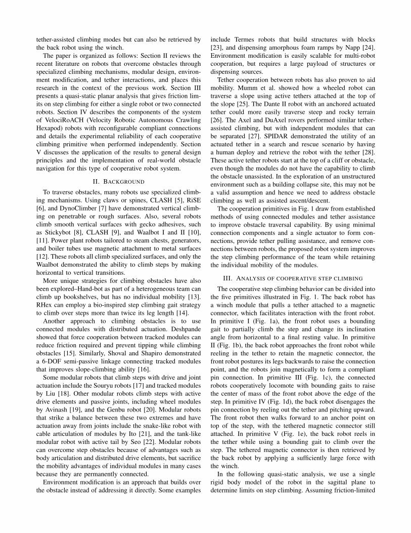
The cooperative step climbing behavior can be divided intothe five primitives illustrated in Fig. 1. The back robot hasa winch module that pulls a tether attached to a magneticconnector, which facilitates interaction with the front robot.In primitive I (Fig. 1a), the front robot uses a boundinggait to partially climb the step and change its inclinationangle from horizontal to a final resting value. In primitiveII (Fig. 1b), the back robot approaches the front robot whilereeling in the tether to retain the magnetic connector, thefront robot postures its legs backwards to raise the connectionpoint, and the robots join magnetically to form a compliantpin connection. In primitive III (Fig. 1c), the connectedrobots cooperatively locomote with bounding gaits to raisethe center of mass of the front robot above the edge of thestep. In primitive IV (Fig. 1d), the back robot disengages thepin connection by reeling out the tether and pitching upward.The front robot then walks forward to an anchor point ontop of the step, with the tethered magnetic connector stillattached. In primitive V (Fig. 1e), the back robot reels inthe tether while using a bounding gait to climb over thestep. The tethered magnetic connector is then retrieved bythe back robot by applying a sufficiently large force withthe winch.
In the following quasi-static analysis, we use a singlerigid body model of the robot in the sagittal plane todetermine limits on step climbing. Assuming friction-limited
m
llg
hg
r
h hl l
δ
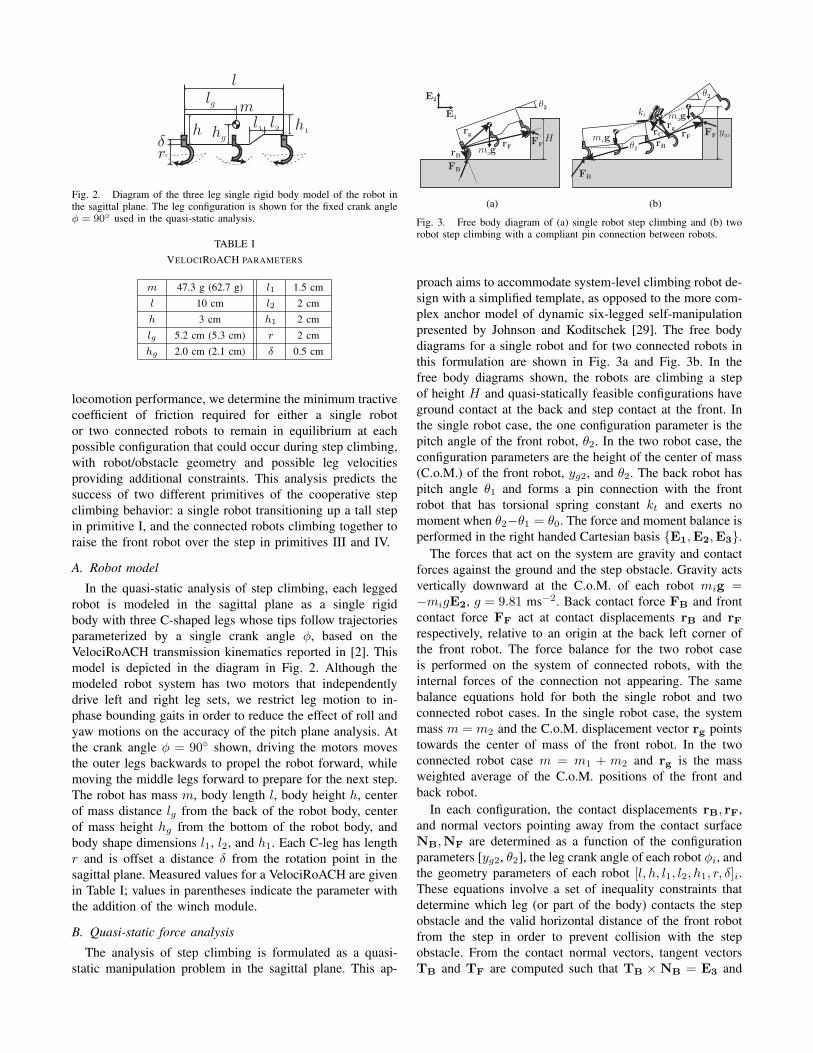
Fig. 2. Diagram of the three leg single rigid body model of the robot inthe sagittal plane. The leg configuration is shown for the fixed crank angleφ = 90 used in the quasi-static analysis.
TABLE IVELOCIROACH PARAMETERS
m 47.3 g (62.7 g) l1 1.5 cm
l 10 cm l2 2 cm
h 3 cm h1 2 cm
lg 5.2 cm (5.3 cm) r 2 cm
hg 2.0 cm (2.1 cm) δ 0.5 cm
locomotion performance, we determine the minimum tractivecoefficient of friction required for either a single robotor two connected robots to remain in equilibrium at eachpossible configuration that could occur during step climbing,with robot/obstacle geometry and possible leg velocitiesproviding additional constraints. This analysis predicts thesuccess of two different primitives of the cooperative stepclimbing behavior: a single robot transitioning up a tall stepin primitive I, and the connected robots climbing together toraise the front robot over the step in primitives III and IV.
A. Robot model
In the quasi-static analysis of step climbing, each leggedrobot is modeled in the sagittal plane as a single rigidbody with three C-shaped legs whose tips follow trajectoriesparameterized by a single crank angle φ, based on theVelociRoACH transmission kinematics reported in [2]. Thismodel is depicted in the diagram in Fig. 2. Although themodeled robot system has two motors that independentlydrive left and right leg sets, we restrict leg motion to in-phase bounding gaits in order to reduce the effect of roll andyaw motions on the accuracy of the pitch plane analysis. Atthe crank angle φ = 90 shown, driving the motors movesthe outer legs backwards to propel the robot forward, whilemoving the middle legs forward to prepare for the next step.The robot has mass m, body length l, body height h, centerof mass distance lg from the back of the robot body, centerof mass height hg from the bottom of the robot body, andbody shape dimensions l1, l2, and h1. Each C-leg has lengthr and is offset a distance δ from the rotation point in thesagittal plane. Measured values for a VelociRoACH are givenin Table I; values in parentheses indicate the parameter withthe addition of the winch module.
B. Quasi-static force analysis
The analysis of step climbing is formulated as a quasi-static manipulation problem in the sagittal plane. This ap-
FB
FF
E1
E2
rBrF
Hrg
θ2
mg
(a)
FF
θ2
rBrF
FB
mg
mgrg
kt
yg
θ1
rC
(b)
Fig. 3. Free body diagram of (a) single robot step climbing and (b) tworobot step climbing with a compliant pin connection between robots.
proach aims to accommodate system-level climbing robot de-sign with a simplified template, as opposed to the more com-plex anchor model of dynamic six-legged self-manipulationpresented by Johnson and Koditschek [29]. The free bodydiagrams for a single robot and for two connected robots inthis formulation are shown in Fig. 3a and Fig. 3b. In thefree body diagrams shown, the robots are climbing a stepof height H and quasi-statically feasible configurations haveground contact at the back and step contact at the front. Inthe single robot case, the one configuration parameter is thepitch angle of the front robot, θ2. In the two robot case, theconfiguration parameters are the height of the center of mass(C.o.M.) of the front robot, yg2, and θ2. The back robot haspitch angle θ1 and forms a pin connection with the frontrobot that has torsional spring constant kt and exerts nomoment when θ2−θ1 = θ0. The force and moment balance isperformed in the right handed Cartesian basis E1,E2,E3.
The forces that act on the system are gravity and contactforces against the ground and the step obstacle. Gravity actsvertically downward at the C.o.M. of each robot mig =−migE2, g = 9.81 ms−2. Back contact force FB and frontcontact force FF act at contact displacements rB and rFrespectively, relative to an origin at the back left corner ofthe front robot. The force balance for the two robot caseis performed on the system of connected robots, with theinternal forces of the connection not appearing. The samebalance equations hold for both the single robot and twoconnected robot cases. In the single robot case, the systemmass m = m2 and the C.o.M. displacement vector rg pointstowards the center of mass of the front robot. In the twoconnected robot case m = m1 + m2 and rg is the massweighted average of the C.o.M. positions of the front andback robot.
In each configuration, the contact displacements rB, rF,and normal vectors pointing away from the contact surfaceNB,NF are determined as a function of the configurationparameters [yg2, θ2], the leg crank angle of each robot φi, andthe geometry parameters of each robot [l, h, l1, l2, h1, r, δ]i.These equations involve a set of inequality constraints thatdetermine which leg (or part of the body) contacts the stepobstacle and the valid horizontal distance of the front robotfrom the step in order to prevent collision with the stepobstacle. From the contact normal vectors, tangent vectorsTB and TF are computed such that TB ×NB = E3 and
TF ×NF = E3.For each set of contact displacements and normal vectors,
a friction-limited force and moment balance is solved todetermine quasi-static limits on step climbing. The vectorforce balance (1) and moment balance about the center ofgravity (2) are given below:
FB + FF −mg = 0 (1)(rB − rg)× FB + (rF − rg)× FF = 0 (2)
For the single robot case, there are three independentequations and four unknowns, two components each for FB
and FF, which yields infinitely many solutions. Assumingthat there is an equal limiting coefficient of friction µ atthe back and front contacts as a limiting case, we imposethe two friction constraints FB·NB = ±µFB·TB andFF·NF = ±µFF·TF. As shown in Fig. 3a, this placesthe contact forces at the edges of friction cones with thesame internal angle. Adding these two constraints whileintroducing an unknown µ reduces the number of unknownsin the system of equations to three, which means there is atmost one solution per branch for ||FB||, ||FF||, and µ.
For the two robot case, an additional equation from thetorsion spring at the pin connection uniquely specifies con-tact forces for a given configuration. Performing a momentbalance on the front robot about the pin connection yieldsthe constitutive equation
(rF − rC)× FF −m2 (rg2 − rC)× g = kt (θ2 − θ1 − θ0)
where rC is the displacement vector to the pin connectioncenter, and rg2 is the C.o.M. displacement of the front robot.
The quasi-static analysis is used to determine frictionlimits on step climbing. Any solutions that cause collisions orrequire adhesion pulling into contact surfaces are disallowed.The limiting coefficients of friction are µB,lim = FB·TB
FB·NBat
the back contact and µF,lim = FF·TF
FF·NFat the front contact.
For the cases shown in Fig. 3, both contact forces indicatea sticking contact with propulsion in order to advance upthe step. In this case, the limiting positive µ is a minimumtractive coefficient of friction. If either contact force isreflected about the normal, the condition would be changedto a sliding contact in order to advance up the step. In thiscase, the limiting negative µ is a maximum sliding coefficientof friction. Therefore, the four cases are: back and frontpropelling, back propelling and front sliding, back slidingand front propelling, and back and front sliding.
In the following quasi-static results for a single robot andtwo connected robots, a high traction obstacle is consideredwith µs = 1, µk = 0.6, where µs and µk are the measuredstatic and dynamic coefficients of friction of a VelociRoACHleg on sandpaper. The leg angles are fixed at φi = 90 forsimplicity of analysis.
C. Quasi-static single robot step climbing
For single robot step climbing, we allow each of the fourcombinations of sticking/sliding contacts, and fix the legcrank angle at φ = 90. For these conditions, Fig. 4 shows
Pitch angle θ2 (deg)0 15 30 45 60
Lim
itingCoF
µ
0 0.20.40.60.81
Both contacts propelBack contact propelsDisallowedTip forward
1 2 3
1 2 F3
(a)
Pitch angle θ2 (deg)0 15 30 45 60
Lim
itingCoF
µ
0 0.20.40.60.81
1
1 2
F2
F
(b)
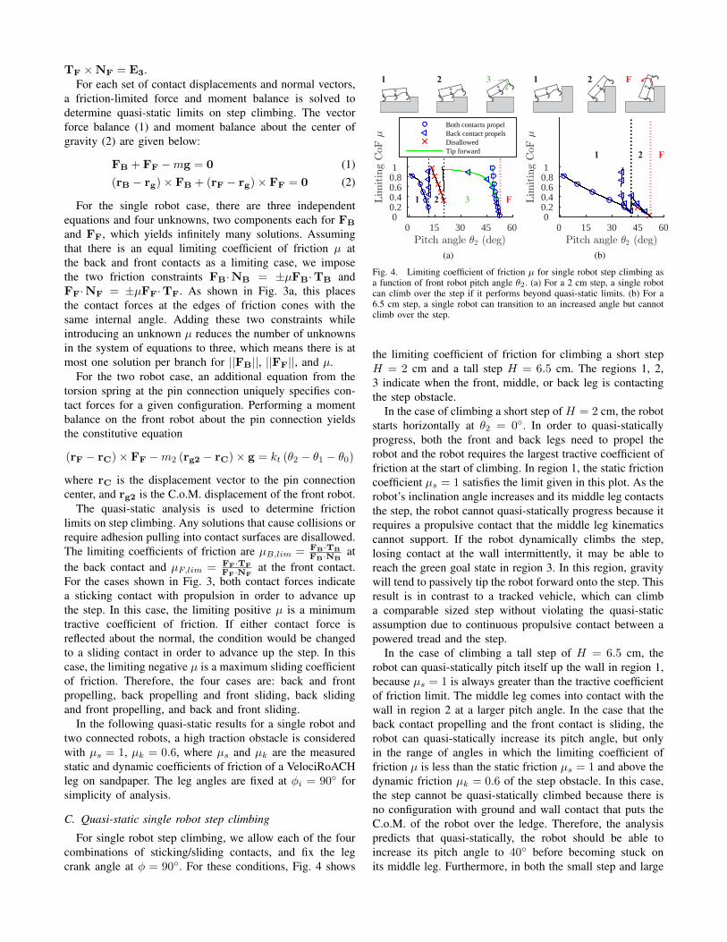
Fig. 4. Limiting coefficient of friction µ for single robot step climbing asa function of front robot pitch angle θ2. (a) For a 2 cm step, a single robotcan climb over the step if it performs beyond quasi-static limits. (b) For a6.5 cm step, a single robot can transition to an increased angle but cannotclimb over the step.
the limiting coefficient of friction for climbing a short stepH = 2 cm and a tall step H = 6.5 cm. The regions 1, 2,3 indicate when the front, middle, or back leg is contactingthe step obstacle.
In the case of climbing a short step of H = 2 cm, the robotstarts horizontally at θ2 = 0. In order to quasi-staticallyprogress, both the front and back legs need to propel therobot and the robot requires the largest tractive coefficient offriction at the start of climbing. In region 1, the static frictioncoefficient µs = 1 satisfies the limit given in this plot. As therobot’s inclination angle increases and its middle leg contactsthe step, the robot cannot quasi-statically progress because itrequires a propulsive contact that the middle leg kinematicscannot support. If the robot dynamically climbs the step,losing contact at the wall intermittently, it may be able toreach the green goal state in region 3. In this region, gravitywill tend to passively tip the robot forward onto the step. Thisresult is in contrast to a tracked vehicle, which can climba comparable sized step without violating the quasi-staticassumption due to continuous propulsive contact between apowered tread and the step.
In the case of climbing a tall step of H = 6.5 cm, therobot can quasi-statically pitch itself up the wall in region 1,because µs = 1 is always greater than the tractive coefficientof friction limit. The middle leg comes into contact with thewall in region 2 at a larger pitch angle. In the case that theback contact propelling and the front contact is sliding, therobot can quasi-statically increase its pitch angle, but onlyin the range of angles in which the limiting coefficient offriction µ is less than the static friction µs = 1 and above thedynamic friction µk = 0.6 of the step obstacle. In this case,the step cannot be quasi-statically climbed because there isno configuration with ground and wall contact that puts theC.o.M. of the robot over the ledge. Therefore, the analysispredicts that quasi-statically, the robot should be able toincrease its pitch angle to 40 before becoming stuck onits middle leg. Furthermore, in both the small step and large
1
2
3
4
Pitch angle θ2 (deg)0 15 30 45 60
Heigh
tyg2(cm)
4
6
8
10
12
14
1 2 3 4
(a)
1
2
3
4
Pitch angle θ2 (deg)0 15 30 45 60
Heigh
tyg2(cm)
4
6
8
10
12
14
Contact cannot propel
Front robot C.o.M. over ledge
1
Tractive limit µ ≤ 0.5
Tractive limit 0.5 < µ ≤ 1
Tractive limit µ > 1Experiment– Initial cfg. Final cfg.
(b)
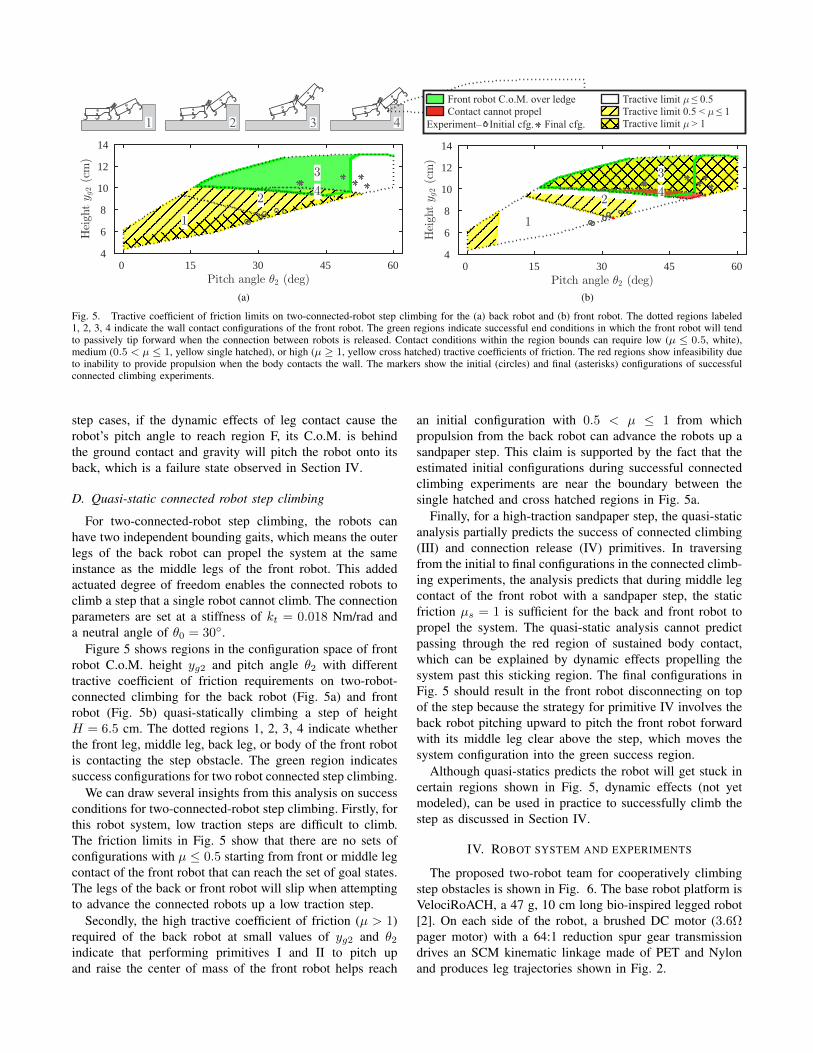
Fig. 5. Tractive coefficient of friction limits on two-connected-robot step climbing for the (a) back robot and (b) front robot. The dotted regions labeled1, 2, 3, 4 indicate the wall contact configurations of the front robot. The green regions indicate successful end conditions in which the front robot will tendto passively tip forward when the connection between robots is released. Contact conditions within the region bounds can require low (µ ≤ 0.5, white),medium (0.5 < µ ≤ 1, yellow single hatched), or high (µ ≥ 1, yellow cross hatched) tractive coefficients of friction. The red regions show infeasibility dueto inability to provide propulsion when the body contacts the wall. The markers show the initial (circles) and final (asterisks) configurations of successfulconnected climbing experiments.
step cases, if the dynamic effects of leg contact cause therobot’s pitch angle to reach region F, its C.o.M. is behindthe ground contact and gravity will pitch the robot onto itsback, which is a failure state observed in Section IV.
D. Quasi-static connected robot step climbing
For two-connected-robot step climbing, the robots canhave two independent bounding gaits, which means the outerlegs of the back robot can propel the system at the sameinstance as the middle legs of the front robot. This addedactuated degree of freedom enables the connected robots toclimb a step that a single robot cannot climb. The connectionparameters are set at a stiffness of kt = 0.018 Nm/rad anda neutral angle of θ0 = 30.
Figure 5 shows regions in the configuration space of frontrobot C.o.M. height yg2 and pitch angle θ2 with differenttractive coefficient of friction requirements on two-robot-connected climbing for the back robot (Fig. 5a) and frontrobot (Fig. 5b) quasi-statically climbing a step of heightH = 6.5 cm. The dotted regions 1, 2, 3, 4 indicate whetherthe front leg, middle leg, back leg, or body of the front robotis contacting the step obstacle. The green region indicatessuccess configurations for two robot connected step climbing.
We can draw several insights from this analysis on successconditions for two-connected-robot step climbing. Firstly, forthis robot system, low traction steps are difficult to climb.The friction limits in Fig. 5 show that there are no sets ofconfigurations with µ ≤ 0.5 starting from front or middle legcontact of the front robot that can reach the set of goal states.The legs of the back or front robot will slip when attemptingto advance the connected robots up a low traction step.
Secondly, the high tractive coefficient of friction (µ > 1)required of the back robot at small values of yg2 and θ2indicate that performing primitives I and II to pitch upand raise the center of mass of the front robot helps reach
an initial configuration with 0.5 < µ ≤ 1 from whichpropulsion from the back robot can advance the robots up asandpaper step. This claim is supported by the fact that theestimated initial configurations during successful connectedclimbing experiments are near the boundary between thesingle hatched and cross hatched regions in Fig. 5a.
Finally, for a high-traction sandpaper step, the quasi-staticanalysis partially predicts the success of connected climbing(III) and connection release (IV) primitives. In traversingfrom the initial to final configurations in the connected climb-ing experiments, the analysis predicts that during middle legcontact of the front robot with a sandpaper step, the staticfriction µs = 1 is sufficient for the back and front robot topropel the system. The quasi-static analysis cannot predictpassing through the red region of sustained body contact,which can be explained by dynamic effects propelling thesystem past this sticking region. The final configurations inFig. 5 should result in the front robot disconnecting on topof the step because the strategy for primitive IV involves theback robot pitching upward to pitch the front robot forwardwith its middle leg clear above the step, which moves thesystem configuration into the green success region.
Although quasi-statics predicts the robot will get stuck incertain regions shown in Fig. 5, dynamic effects (not yetmodeled), can be used in practice to successfully climb thestep as discussed in Section IV.
IV. ROBOT SYSTEM AND EXPERIMENTS
The proposed two-robot team for cooperatively climbingstep obstacles is shown in Fig. 6. The base robot platform isVelociRoACH, a 47 g, 10 cm long bio-inspired legged robot[2]. On each side of the robot, a brushed DC motor (3.6Ωpager motor) with a 64:1 reduction spur gear transmissiondrives an SCM kinematic linkage made of PET and Nylonand produces leg trajectories shown in Fig. 2.
(a) (b)
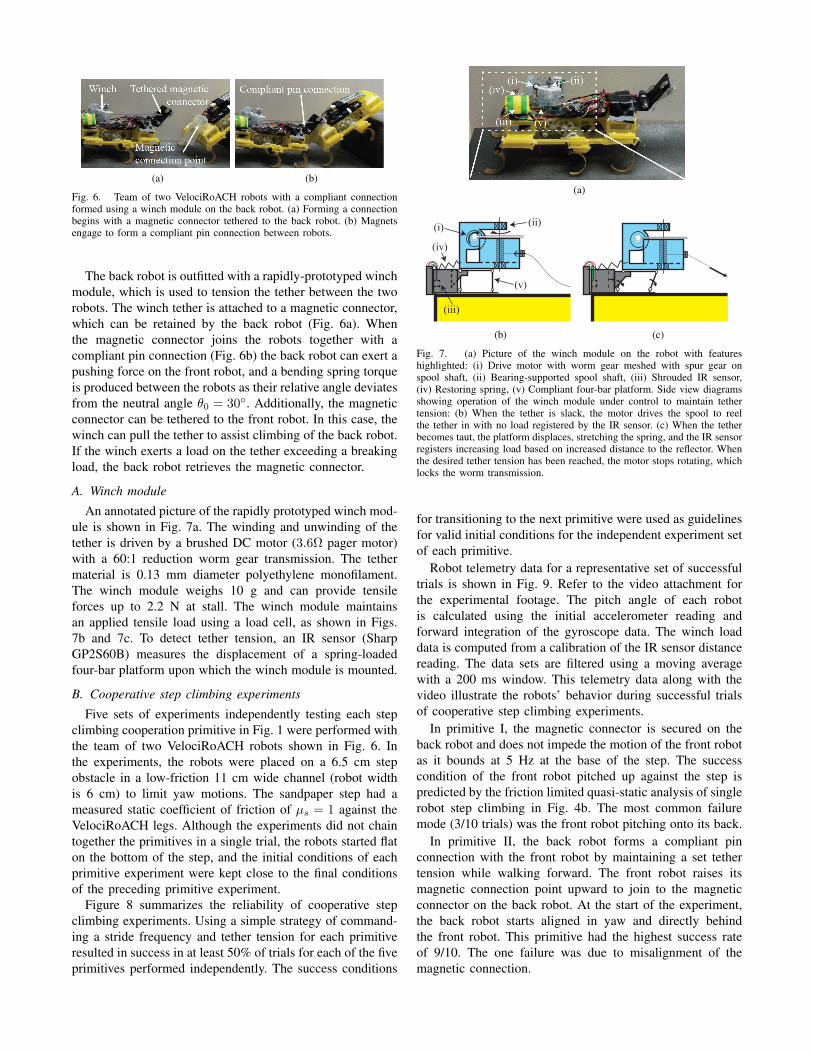
Fig. 6. Team of two VelociRoACH robots with a compliant connectionformed using a winch module on the back robot. (a) Forming a connectionbegins with a magnetic connector tethered to the back robot. (b) Magnetsengage to form a compliant pin connection between robots.
The back robot is outfitted with a rapidly-prototyped winchmodule, which is used to tension the tether between the tworobots. The winch tether is attached to a magnetic connector,which can be retained by the back robot (Fig. 6a). Whenthe magnetic connector joins the robots together with acompliant pin connection (Fig. 6b) the back robot can exert apushing force on the front robot, and a bending spring torqueis produced between the robots as their relative angle deviatesfrom the neutral angle θ0 = 30. Additionally, the magneticconnector can be tethered to the front robot. In this case, thewinch can pull the tether to assist climbing of the back robot.If the winch exerts a load on the tether exceeding a breakingload, the back robot retrieves the magnetic connector.
A. Winch module
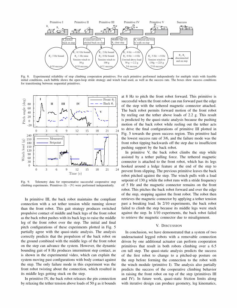
An annotated picture of the rapidly prototyped winch mod-ule is shown in Fig. 7a. The winding and unwinding of thetether is driven by a brushed DC motor (3.6Ω pager motor)with a 60:1 reduction worm gear transmission. The tethermaterial is 0.13 mm diameter polyethylene monofilament.The winch module weighs 10 g and can provide tensileforces up to 2.2 N at stall. The winch module maintainsan applied tensile load using a load cell, as shown in Figs.7b and 7c. To detect tether tension, an IR sensor (SharpGP2S60B) measures the displacement of a spring-loadedfour-bar platform upon which the winch module is mounted.
B. Cooperative step climbing experiments
Five sets of experiments independently testing each stepclimbing cooperation primitive in Fig. 1 were performed withthe team of two VelociRoACH robots shown in Fig. 6. Inthe experiments, the robots were placed on a 6.5 cm stepobstacle in a low-friction 11 cm wide channel (robot widthis 6 cm) to limit yaw motions. The sandpaper step had ameasured static coefficient of friction of µs = 1 against theVelociRoACH legs. Although the experiments did not chaintogether the primitives in a single trial, the robots started flaton the bottom of the step, and the initial conditions of eachprimitive experiment were kept close to the final conditionsof the preceding primitive experiment.
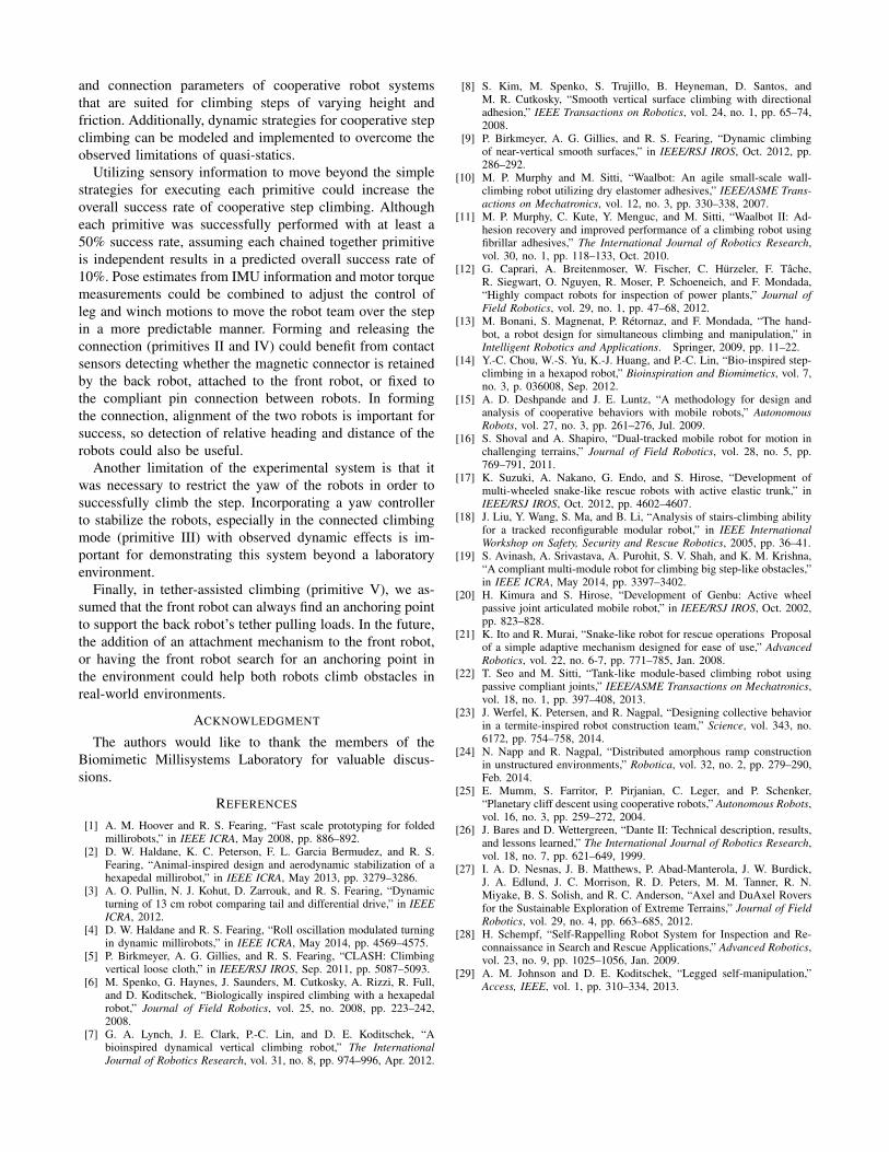
Figure 8 summarizes the reliability of cooperative stepclimbing experiments. Using a simple strategy of command-ing a stride frequency and tether tension for each primitiveresulted in success in at least 50% of trials for each of the fiveprimitives performed independently. The success conditions
(a)
(i)(ii)
(iii)
(iv)
(v)
(b) (c)
Fig. 7. (a) Picture of the winch module on the robot with featureshighlighted: (i) Drive motor with worm gear meshed with spur gear onspool shaft, (ii) Bearing-supported spool shaft, (iii) Shrouded IR sensor,(iv) Restoring spring, (v) Compliant four-bar platform. Side view diagramsshowing operation of the winch module under control to maintain tethertension: (b) When the tether is slack, the motor drives the spool to reelthe tether in with no load registered by the IR sensor. (c) When the tetherbecomes taut, the platform displaces, stretching the spring, and the IR sensorregisters increasing load based on increased distance to the reflector. Whenthe desired tether tension has been reached, the motor stops rotating, whichlocks the worm transmission.
for transitioning to the next primitive were used as guidelinesfor valid initial conditions for the independent experiment setof each primitive.
Robot telemetry data for a representative set of successfultrials is shown in Fig. 9. Refer to the video attachment forthe experimental footage. The pitch angle of each robotis calculated using the initial accelerometer reading andforward integration of the gyroscope data. The winch loaddata is computed from a calibration of the IR sensor distancereading. The data sets are filtered using a moving averagewith a 200 ms window. This telemetry data along with thevideo illustrate the robots’ behavior during successful trialsof cooperative step climbing experiments.
In primitive I, the magnetic connector is secured on theback robot and does not impede the motion of the front robotas it bounds at 5 Hz at the base of the step. The successcondition of the front robot pitched up against the step ispredicted by the friction limited quasi-static analysis of singlerobot step climbing in Fig. 4b. The most common failuremode (3/10 trials) was the front robot pitching onto its back.
In primitive II, the back robot forms a compliant pinconnection with the front robot by maintaining a set tethertension while walking forward. The front robot raises itsmagnetic connection point upward to join to the magneticconnector on the back robot. At the start of the experiment,the back robot starts aligned in yaw and directly behindthe front robot. This primitive had the highest success rateof 9/10. The one failure was due to misalignment of themagnetic connection.
R1 R
2
Primitive I Primitive II Primitive III Primitive IV Primitive V Success
R1: 8 Hz → 0 Hz
R2: 0 Hz → 4 Hz
Unwind above load
50 g → 2.2 g
3/6 success
R2: 5 Hz bound
6/10 success
R1: 0.5 Hz bound
R2: 1 Hz raise
Tension winch to
50 g
9/10 success
R1: 2 Hz bound
R2: 8 Hz bound
Tension winch to
100 g
6/11 success
R2: 5 Hz → 0 Hz
Tension winch to
130g → 225 g
7/10 success
R2 pitched
back on step
Connected and R2
pitched back on step
Middle legs of
R2 clear step
R2 tethered and free
to walk on step
R1, R
2
disconnected
and on step
Fig. 8. Experimental reliability of step climbing cooperation primitives. For each primitive performed independently for multiple trials with feasibleinitial conditions, each bubble shows the open-loop stride strategy and winch load used, as well as the success rate. The boxes show success conditionsfor transitioning between sequential primitives.
Time (s)0 3 6 9 12 15 18 21 24
Pitch
angle(deg)
-200
20 40 60 80
Front θ2Back θ1
Time (s)0 3 6 9 12 15 18 21 24
Winch
load
(g)
0 30 60 90
120150180210240
MeasuredSetpoint
I
II III IV
V
Fig. 9. Telemetry data for representative successful cooperative stepclimbing experiments. Primitives (I) - (V) were performed independently.
In primitive III, the back robot maintains the compliantconnection with a set tether tension while running slowerthan the front robot. This gait strategy produces switchedpropulsive contact of middle and back legs of the front robotas the back robot pushes with its back legs to raise the middleleg of the front robot over the step. The initial and finalpitch configurations of these experiments plotted in Fig. 5partially agree with the quasi-static analysis. The analysiscorrectly predicts that the propulsion of the back robot onthe ground combined with the middle legs of the front roboton the step can advance the system. However, the dynamicbounding gait of 8 Hz produces intermittent step contact, asis shown in the experimental video, which can explain thesystem moving past configurations with body contact againstthe step. The only failure mode in this experiment was thefront robot twisting about the connection, which resulted inits middle legs getting stuck on the step.
In primitive IV, the back robot releases the pin connectionby relaxing the tether tension above loads of 50 g as it bounds
at 8 Hz to pitch the front robot forward. This primitive issuccessful when the front robot can run forward past the edgeof the step with the tethered magnetic connector attached.The back robot permits forward motion of the front robotby reeling out the tether above loads of 2.2 g. This resultis predicted by the quasi-static analysis because the pushingmotion of the back robot while reeling out the tether actsto drive the final configurations of primitive III plotted inFig. 5 towards the green success region. This primitive hadthe lowest success rate of 3/6, and the failure mode was thefront robot tipping backwards off the step due to insufficientpushing support by the back robot.
In primitive V, the back robot climbs the step whileassisted by a tether pulling force. The tethered magneticconnector is attached to the front robot, which has its legshooked around a ledge feature at the end of the step toprevent from slipping. The previous primitive leaves the backrobot pitched against the step. The winch pulls with a loadsetpoint of 130 g while the robot runs with a stride frequencyof 5 Hz and the magnetic connector remains on the frontrobot. This pitches the back robot forward and over the edgeof the step, stopping against the front robot. The robot thenretrieves the magnetic connector by applying a tether tensionpast a breaking load. In 2/10 experiments, the back robotfailed to climb the step because its middle legs were stuckagainst the step. In 1/10 experiments, the back robot failedto retrieve the magnetic connector due to misalignment.
V. DISCUSSION
In conclusion, we have demonstrated that a system of twounderactuated legged robots with a removable connectiondriven by one additional actuator can perform cooperationprimitives that result in both robots climbing over a 6.5cm tall step. The quasi-static analysis predicts the successof the first robot to change to a pitched-up posture onthe step before forming the connection to the robot withthe winch module (primitive I). The analysis also partiallypredicts the success of the cooperative climbing behaviorin raising the front robot on top of the step (primitives IIIand IV). In future work, quasi-static friction limits alongwith iterative design can produce geometry, leg kinematics,
and connection parameters of cooperative robot systemsthat are suited for climbing steps of varying height andfriction. Additionally, dynamic strategies for cooperative stepclimbing can be modeled and implemented to overcome theobserved limitations of quasi-statics.
Utilizing sensory information to move beyond the simplestrategies for executing each primitive could increase theoverall success rate of cooperative step climbing. Althougheach primitive was successfully performed with at least a50% success rate, assuming each chained together primitiveis independent results in a predicted overall success rate of10%. Pose estimates from IMU information and motor torquemeasurements could be combined to adjust the control ofleg and winch motions to move the robot team over the stepin a more predictable manner. Forming and releasing theconnection (primitives II and IV) could benefit from contactsensors detecting whether the magnetic connector is retainedby the back robot, attached to the front robot, or fixed tothe compliant pin connection between robots. In formingthe connection, alignment of the two robots is important forsuccess, so detection of relative heading and distance of therobots could also be useful.
Another limitation of the experimental system is that itwas necessary to restrict the yaw of the robots in order tosuccessfully climb the step. Incorporating a yaw controllerto stabilize the robots, especially in the connected climbingmode (primitive III) with observed dynamic effects is im-portant for demonstrating this system beyond a laboratoryenvironment.
Finally, in tether-assisted climbing (primitive V), we as-sumed that the front robot can always find an anchoring pointto support the back robot’s tether pulling loads. In the future,the addition of an attachment mechanism to the front robot,or having the front robot search for an anchoring point inthe environment could help both robots climb obstacles inreal-world environments.
ACKNOWLEDGMENT
The authors would like to thank the members of theBiomimetic Millisystems Laboratory for valuable discus-sions.
REFERENCES
[1] A. M. Hoover and R. S. Fearing, “Fast scale prototyping for foldedmillirobots,” in IEEE ICRA, May 2008, pp. 886–892.
[2] D. W. Haldane, K. C. Peterson, F. L. Garcia Bermudez, and R. S.Fearing, “Animal-inspired design and aerodynamic stabilization of ahexapedal millirobot,” in IEEE ICRA, May 2013, pp. 3279–3286.
[3] A. O. Pullin, N. J. Kohut, D. Zarrouk, and R. S. Fearing, “Dynamicturning of 13 cm robot comparing tail and differential drive,” in IEEEICRA, 2012.
[4] D. W. Haldane and R. S. Fearing, “Roll oscillation modulated turningin dynamic millirobots,” in IEEE ICRA, May 2014, pp. 4569–4575.
[5] P. Birkmeyer, A. G. Gillies, and R. S. Fearing, “CLASH: Climbingvertical loose cloth,” in IEEE/RSJ IROS, Sep. 2011, pp. 5087–5093.
[6] M. Spenko, G. Haynes, J. Saunders, M. Cutkosky, A. Rizzi, R. Full,and D. Koditschek, “Biologically inspired climbing with a hexapedalrobot,” Journal of Field Robotics, vol. 25, no. 2008, pp. 223–242,2008.
[7] G. A. Lynch, J. E. Clark, P.-C. Lin, and D. E. Koditschek, “Abioinspired dynamical vertical climbing robot,” The InternationalJournal of Robotics Research, vol. 31, no. 8, pp. 974–996, Apr. 2012.
[8] S. Kim, M. Spenko, S. Trujillo, B. Heyneman, D. Santos, andM. R. Cutkosky, “Smooth vertical surface climbing with directionaladhesion,” IEEE Transactions on Robotics, vol. 24, no. 1, pp. 65–74,2008.
[9] P. Birkmeyer, A. G. Gillies, and R. S. Fearing, “Dynamic climbingof near-vertical smooth surfaces,” in IEEE/RSJ IROS, Oct. 2012, pp.286–292.
[10] M. P. Murphy and M. Sitti, “Waalbot: An agile small-scale wall-climbing robot utilizing dry elastomer adhesives,” IEEE/ASME Trans-actions on Mechatronics, vol. 12, no. 3, pp. 330–338, 2007.
[11] M. P. Murphy, C. Kute, Y. Menguc, and M. Sitti, “Waalbot II: Ad-hesion recovery and improved performance of a climbing robot usingfibrillar adhesives,” The International Journal of Robotics Research,vol. 30, no. 1, pp. 118–133, Oct. 2010.
[12] G. Caprari, A. Breitenmoser, W. Fischer, C. Hurzeler, F. Tache,R. Siegwart, O. Nguyen, R. Moser, P. Schoeneich, and F. Mondada,“Highly compact robots for inspection of power plants,” Journal ofField Robotics, vol. 29, no. 1, pp. 47–68, 2012.
[13] M. Bonani, S. Magnenat, P. Retornaz, and F. Mondada, “The hand-bot, a robot design for simultaneous climbing and manipulation,” inIntelligent Robotics and Applications. Springer, 2009, pp. 11–22.
[14] Y.-C. Chou, W.-S. Yu, K.-J. Huang, and P.-C. Lin, “Bio-inspired step-climbing in a hexapod robot,” Bioinspiration and Biomimetics, vol. 7,no. 3, p. 036008, Sep. 2012.
[15] A. D. Deshpande and J. E. Luntz, “A methodology for design andanalysis of cooperative behaviors with mobile robots,” AutonomousRobots, vol. 27, no. 3, pp. 261–276, Jul. 2009.
[16] S. Shoval and A. Shapiro, “Dual-tracked mobile robot for motion inchallenging terrains,” Journal of Field Robotics, vol. 28, no. 5, pp.769–791, 2011.
[17] K. Suzuki, A. Nakano, G. Endo, and S. Hirose, “Development ofmulti-wheeled snake-like rescue robots with active elastic trunk,” inIEEE/RSJ IROS, Oct. 2012, pp. 4602–4607.
[18] J. Liu, Y. Wang, S. Ma, and B. Li, “Analysis of stairs-climbing abilityfor a tracked reconfigurable modular robot,” in IEEE InternationalWorkshop on Safety, Security and Rescue Robotics, 2005, pp. 36–41.
[19] S. Avinash, A. Srivastava, A. Purohit, S. V. Shah, and K. M. Krishna,“A compliant multi-module robot for climbing big step-like obstacles,”in IEEE ICRA, May 2014, pp. 3397–3402.
[20] H. Kimura and S. Hirose, “Development of Genbu: Active wheelpassive joint articulated mobile robot,” in IEEE/RSJ IROS, Oct. 2002,pp. 823–828.
[21] K. Ito and R. Murai, “Snake-like robot for rescue operations Proposalof a simple adaptive mechanism designed for ease of use,” AdvancedRobotics, vol. 22, no. 6-7, pp. 771–785, Jan. 2008.
[22] T. Seo and M. Sitti, “Tank-like module-based climbing robot usingpassive compliant joints,” IEEE/ASME Transactions on Mechatronics,vol. 18, no. 1, pp. 397–408, 2013.
[23] J. Werfel, K. Petersen, and R. Nagpal, “Designing collective behaviorin a termite-inspired robot construction team,” Science, vol. 343, no.6172, pp. 754–758, 2014.
[24] N. Napp and R. Nagpal, “Distributed amorphous ramp constructionin unstructured environments,” Robotica, vol. 32, no. 2, pp. 279–290,Feb. 2014.
[25] E. Mumm, S. Farritor, P. Pirjanian, C. Leger, and P. Schenker,“Planetary cliff descent using cooperative robots,” Autonomous Robots,vol. 16, no. 3, pp. 259–272, 2004.
[26] J. Bares and D. Wettergreen, “Dante II: Technical description, results,and lessons learned,” The International Journal of Robotics Research,vol. 18, no. 7, pp. 621–649, 1999.
[27] I. A. D. Nesnas, J. B. Matthews, P. Abad-Manterola, J. W. Burdick,J. A. Edlund, J. C. Morrison, R. D. Peters, M. M. Tanner, R. N.Miyake, B. S. Solish, and R. C. Anderson, “Axel and DuAxel Roversfor the Sustainable Exploration of Extreme Terrains,” Journal of FieldRobotics, vol. 29, no. 4, pp. 663–685, 2012.
[28] H. Schempf, “Self-Rappelling Robot System for Inspection and Re-connaissance in Search and Rescue Applications,” Advanced Robotics,vol. 23, no. 9, pp. 1025–1056, Jan. 2009.
[29] A. M. Johnson and D. E. Koditschek, “Legged self-manipulation,”Access, IEEE, vol. 1, pp. 310–334, 2013.


![Experimental and Numerical Optimization of Magnetic ... · passive. Passive suction cups do not use an energy supply to attach to the surface. In [7] a legged wall climbing robot](https://img.pdfslide.net/doc/110x75/5eda7a95b3745412b571697d/experimental-and-numerical-optimization-of-magnetic-passive-passive-suction.jpg)