Embed Size (px)
Citation preview
International Journal of Advanced Engineering Research and Studies E-ISSN2249–8974
IJAERS/Vol. I/ Issue III/April-June, 2012/178-180
Research Paper
STEPPER MOTOR DRIVE FOR HIGH SPEED CONTROL BY
HIGH VOLTAGE & CONSTANT CURRENT 1J G Gajipara,
2Prof K A Sonagara,
Address for Correspondence 1ME Electrical,
2Asst. Professor, Govt. Engg College, Bhuj, Gujarat, India
ABSTRACT In Today’s era with growing demand towards motion control applications which consist of stepper motor, where some of
application required the high speed and holding torque control to increase the production. Generally stepper motor dive are
not to design for high speed application. Here one topology is given how to achieve high speed as well as holding torque
control in hybrid stepper motor.
KEYWORDS HPM Drive, HPM High Speed, HPM holding torque
1. INTRODUCTION
IN this paper one topology is given to control high
speed and holding torque control Hybrid Stepper
Motor (HPM).Whenever we are using HPM as
motion control solution in the industry where
sequential process is going on, for such application if
we are going with high speed than we can increase
production by keeping that in mind this method is
given.
2. HIGH VOLTAGE SUPPLY FOR HPM HIGH
SPEED
It has been found that when the HPM start to rotate it
will develop the back emf stator winding. Fig. 1
shows the equivalent circuit for the HPM Drive. At
starting there is no back emf (Eb) so Current in the
winding flow SA1 and SA2 will Close which is given
by Eq. (1) for any random Sequence.
It= Im (1-e-t/τ) (1)
Where, Im= (Vdc/RA),
τ = LA/RA,
RA=Winding resistance of any one phase,
LA=Winding inductance of any one phase,
Vdc=supply voltage,
Im=Ir =Rated Current for rated torque.
Fig.1
Now HPM is on speed N1, so it has its back emf
say it Eb1,
Im= ((Vdc-Eb1)/R),
It = ((Vdc-Eb1)/R) X (1-e-t/τ) (2)
When HPM is at low speed value of back emf Eb is
not so much high, HPM do its work faith Fully but at
a high speed due to back emf, Im is Decrease and so
motor can take its rated load. Second thing at high
acceleration we face the slip of the rotor. In this way
if we want to go for higher speed or high
acceleration, we have to decrease load on motor. As
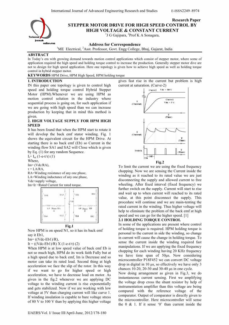
given in the fig.2 whenever we are applying DC
voltage to the winding current is rise exponentially
and gets stabilized. Now if we are working with low
voltage at 5V than charging current will like curve 1.
If winding insulation is capable to bare voltage stress
of 80 V to 100 V than by applying this higher voltage
gives fast rise in the current but problem is high
current at saturation. (Curve-2)
Fig.2
To limit the current we are using the fixed frequency
chopping. Now we are sensing the Current inside the
winding as it reached to its rated value we are just
disconnecting the supply and allowed current to free
wheeling. After fixed interval (fixed frequency) we
further switch on the supply. Current will start to rise
and wait up to when current will reached to its rated
value, at this point disconnect the supply. This
procedure will continue and we are main-tenting the
rated current in the winding. Thus higher voltage will
help to eliminate the problem of the back emf at high
speed and we can go for the higher speed. [1]
2.1 HOLDING TORQUE CONTROL
In some of the applications are present where control
of holding torque is required. HPM holding torque is
personal to the current in side the winding, so change
in current will cause the change in holding torque. To
sense the current inside the winding required fast
manipulations. If we are applying the fixed frequency
chopping for each winding having 20 KHz frequency
we have time span of 50µs. Now considering
microcontroller P18F452 we can convert DC voltage
drop in digital in 10 µs, so effectively we have only 3
chances 10-20, 20-30 and 30-40 µs in one cycle.
Now doing arrangement as given in Fig.3, we do
instantaneous current sensing. First we amplifying
the voltage drop cross the shunt resistor by help of
instrumentation amplifier than this voltage are being
compared with the reference voltage of the
comparator. Output of comparator is directly given to
the microcontroller. Here microcontroller will sense
the 0 & 1. If it sense ‘0’ than current inside the

International Journal of Advanced Engineering Research and Studies E-ISSN2249–8974
IJAERS/Vol. I/ Issue III/April-June, 2012/178-180
winding is less than the required, for this condition
we allowed to raise the current. If it sense ‘1’ than
current inside the winding is grater than the required,
for this condition we just take out the supply and
allowed to fall in current by freewheeling. We are
energizing the winding only after completion of one
cycle (50 µs). Thus by changing the reference we can
change the holding torque. [2]
2.2GENERATION OF CONTROL SIGNALS
As given in to the fig.3 we can’t switch on two
switches of one lag at a same time because it will
create dead short-circuit on available DC link level.
Drivers are available in market which take one input
and generate two outputs have one inverted facility.
So we have to generate control signal A, B, C and D
which is going to control the SA1-SA4, SA3-SA2,
SB1-SB4 and SB3-SB2. Fig.4 shows the control
signal required to drivers A, B, C and D. They all are
work on fixed frequency. Table -1 shows the tabular
formte of the control signals.
Fig.3
Fig.4
2.3 Algorithm For Generation Of Control Signals
Main flow chart:
• Link the library files to MPLAB software.
• Declaring variables and arrays for the
program, declaring names of the I/O pins.
• Deciding which I/O pin work as input and
which pin work as output.
• Checking the status of the inputs and store
it.
• Set the mode of operation and direction by
status of inputs.
• Blink all LEDs indication for the 1s to check
the LEDs are working and drive is
configured.
• Wait for ENABLE pulse.
• After getting ENABLE first enable all
interrupts than start to continuously
monitoring the STOP input as an when
STOP come drive is reset the all variables.
Fig.5 (Main Flow Chart)
2.4 Interrupt flow chart:
1) We are using four interrupts INT0, INT1, INT2
and TIMER2 which are assign for work CLOCK
monitoring, winding 1 current is higher than the
rated, winding 2 current is higher than the rated and
to generate fixed frequency chopping. 2) Here this
microcontroller (P16F452) has two types of interrupt
service retinue address high priority and low priority.
3) We are keeping INT0, INT1, INT2 in high priority
and TIMER2 in low priority. 4) When a CLOCK
come, INT0 is generate program counter will move to
high priority address and next sequence of A, B, C
and D are generated. 5) When current inside the
winding 1 will goes higher than rated INT1 is
generated, first it will check output A is on (i.e.
A==1) if yes than A will switch off (i.e. A=0), if not
than will check output B is on (i.e. B==1) if yes than
B will switch off (i.e. B=0). 6) When current inside
the winding 2 will goes higher than rated INT2 is
generated, first it will check output C is on (i.e.
C==1) if yes than C will switch off (i.e. C=0), if not
than will check output D is on (i.e. D==1) if yes than
D will switch off (i.e. D=0). 7) When TIMER2 value
becomes 0000H, TIMER2 interrupt will generate, it
will load original value of outputs A, B, C and D.

International Journal of Advanced Engineering Research and Studies E-ISSN2249–8974
IJAERS/Vol. I/ Issue III/April-June, 2012/178-180
Fig.6 (Interrupt routine)
3. CONCLUSION:
It has been found that fixed frequency chopping
method can used to control the high speed as well as
at high acceleration. Here drive can easily ableto
control the holding torque. This method is required to
sense the only o/p comparator so no need to go for A
to D conversion and so, this drive can easily develop
by the microcontroller (P16F452) only.
REFRENCES 1. V.V.Athani, “Stepper Motors
Fundamentals,Application and Design”, ch. 4, pp. 31-
65, NewAge International (P) Limited, New Delhi,
2000. 2. V.V.Athani, and J.C. Mundha, “High Performance
Controller for High Torque PM Stepping Motor”, IEEE
Trans. on Industrial Electronic. Vol. IECI-25, No. 4, pp.343-346, 1978.
3. Reston Condit, Dr. Douglas W. Jones, “Stepping
Motors Fundamentals” (AN907), pp. 10-14, Microchip, 2004
4. Crnosija, P.; Kuzmanovic, B.; Ajdukovic, S. ,
“Microcomputer implementation of optimal algorithms for closed-loop control of hybrid stepper motor drive”,
IEEE Transactions on Industrial Electronics, Volume
47, Issue 6, pp. 1319 – 132, Dec 2000. 5. M.H. Rasid, “Power Electronics, Circuits, Devices and
Applications”, ch. 9, pp. 406-430, Prentice-Hall, India,
2007