Embed Size (px)
Citation preview

Stereo and 3D VideoYao WangYao Wang
Polytechnic Institute of New York UniversityBrooklyn, NY11201
(with significant contribution from Amy Reibman)

Ranges of applications for 3D
• Understanding the world around us using vision systems• Understanding the world around us, using vision systems– Acquisition and interpretation of 3D
C i ti d i ti th ld d• Communicating, depicting the world around us– Stereo, free viewpoint TV– Telling a more compelling story
ARReibman, 2011 Stereo and 3D Video 2

Outline
• Understanding the 3D world: Geometry• Understanding the 3D world: Geometry– Acquisition: geometry of parallel and converged cameras– Depth from disparity
Finding correspondences; disparity estimation– Finding correspondences; disparity estimation– Rectification – Intermediate view synthesis
H d th ti• Human depth perception– Depth cues– Fusion
Wh t f ti ?– What causes eye fatigues?– Other related phenomena
• Displays: stereo, autostereoscopic, volumetric
Stereo Sequence Processing 3
• Communication: Stereo and multiview sequence coding– MPEG-2 Temporal scalability and H.264 Multiview coding

Depth Perception by Stereopsis
• Human eye perceives depth by having two eyes with slightly• Human eye perceives depth by having two eyes with slightly shifted views – The shift is called “disparity”
Perceived depth depends on the the “disparity”– Perceived depth depends on the the disparity• There are other monocular cues for depth perception
– E.g. far away objects look smaller
©Yao Wang, 2007 Stereo Sequence Processing 4
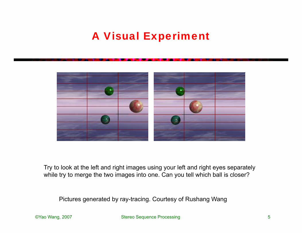
A Visual Experiment
Try to look at the left and right images using your left and right eyes separately while try to merge the two images into one. Can you tell which ball is closer?
©Yao Wang, 2007 Stereo Sequence Processing 5
Pictures generated by ray-tracing. Courtesy of Rushang Wang

A Visual Experiment
Try to look at the left and right images by crossing your left and right eyes while trying to merge the two images into one. Can you tell which ball is closer?
Different people merge left and right views differently: wall or cross
©Yao Wang, 2007 Stereo Sequence Processing 6
Different people merge left and right views differently: wall or cross
Pictures generated by ray-tracing. Courtesy of Rushang Wang

Stereo Imaging Configuration:AcquisitionAcquisition
• Live action• Live action– Parallel configuration– Converging
• Animation– Computer generated animation uses native 3D modeling
Addi i l i ( ) il b d d
Stereo and 3D video 7
– Additional view(s) can easily be rendered
JBoyce, 2011

Perspective Projection Revisited
X All points in this ray will h th iY
YZ
X
have the same image
X
x
x
y
x
y Z
X
F
ZYFy
ZXFx
ZY
Fy
ZX
Fx ,,
C
(a)
©Yao Wang, 2007 Stereo Sequence Processing 8
ZyxZZZFZF
torelatedinversely are ,

Parallel Camera Configuration
©Yao Wang, 2007 Stereo Sequence Processing 9
i) Only horizontal disparityii) Disparity is inversely proportional to Ziii) Range of disparity increases with B

Disparity and Depth
Negative disparity:Object in front of the screen
Positive disparityObject behind the screen
ARReibman, 2011 Stereo and 3D Video 10
Object in front of the screen Object behind the screen

Convergent Camera Configuration
• See text• See text
both horizontal and vertical disparity
©Yao Wang, 2007 Stereo Sequence Processing 11
both horizontal and vertical disparity

Example Images(Converging Camera)(Converging Camera)
Notice the keystone effectCan get a better depth perception of objects closer to the camera than with the parallel set upBut when displayed using a parallel projection system and viewed by the human eye, the vertical disparity causes perceptual discomfort. Geometric correction is needed before
©Yao Wang, 2007 Stereo Sequence Processing 12
vertical disparity causes perceptual discomfort. Geometric correction is needed before displaying these images.

Epipolar Geometry: Arbitrary Case
: Epipolar plane
ep l : Epipolar linesep l,r: Epipolar lines
[F]: fundamental matrix,Depends on camera setup
©Yao Wang, 2007 Stereo Sequence Processing 13
Epipolar constraint: For any point that is on the left epipolar line in the left image, its corresponding point in the right image must be on the epipolar line, and vice versa.

Epipolar Geometry: Parallel Case
• Epipolar constraint: the corresponding left and right image points• Epipolar constraint: the corresponding left and right image points should be on the same horizontal line (only horizontal disparity exists)
©Yao Wang, 2007 Stereo Sequence Processing 14
Rectification: creation of images as if acquired from parallel cameras

Disparity Estimation
• Disparity Estimation Problem:• Disparity Estimation Problem:– For each point in one (anchor) image, find its corresponding point in the
other (target) image – Similar to motion estimation problem– Parallel configuration: only horizontal disparity needs to be estimated.– Difference from motion estimation: Has more physical constraints; disparity
range may be very large for objects nearby (up to 40-50 pixels)– Problem set-up:
• Determine disparity at every pixel to minimize Disparity Compensated PredictionDetermine disparity at every pixel to minimize Disparity Compensated Prediction (DCP) error
• Constraints for disparity estimation• Block-based disparity estimation• Mesh-based disparity estimation• 3D structure estimation
©Yao Wang, 2007 Stereo Sequence Processing 15

Constraints for Disparity Estimation
• Epipolar constraints:• Epipolar constraints:– For parallel set up: two corresponding points are in the same line,
only horizontal disparity need to be searched– For an arbitrary camera set up: given x r possible x l sits on a lineFor an arbitrary camera set up: given x_r, possible x_l sits on a line
(epipolar line)• Ordering constraint:
– If two points in the right image are such thatIf two points in the right image are such that– Then the corresponding two points in the left image satisfy
• Models for disparity functions
©Yao Wang, 2007 Stereo Sequence Processing 16

Models for Disparity Functions
• Affine model for plane surface parallel set up:• Affine model for plane surface, parallel set-up:– If an imaged object has a plane surface
then the disparity function for points on the surface satisfies affine model:
• For an arbitrary scene, we can divide the reference (right) image i t ll bl k th t th bj t f di tinto small blocks so that the object surface corresponding to each block is approximately flat. Then the disparity function over each block can be modeled as affine.U i i il h d i d l f d f
©Yao Wang, 2007 Stereo Sequence Processing 17
• Using similar approach, can derive models for curved surfaces (higher order polynomial)

Block-Based Disparity Estimation
• Following the method for block based motion estimation• Following the method for block-based motion estimation– Divide the anchor image into regular blocks– Assume disparity function over each block is constant or an affine
functionfunction– Determine the constant or the affine parameters– For parallel set up: Only1 horizontal disparity or 3 affine parameters
• Difference from motion estimation• Difference from motion estimation– Constant disparity model is less effective than constant motion
model even over small blocks– Affine model is quite goodAffine model is quite good– Need a large search range to account for disparities in objects
nearby
©Yao Wang, 2007 Stereo Sequence Processing 18

Intermediate View Synthesis
• Problem:• Problem:– Interpolate intermediate views from given views– Necessary for virtual reality applications
Linear interpolation can lead to bl rred images• Linear interpolation: can lead to blurred images
• Disparity-compensated interpolation
©Yao Wang, 2007 Stereo Sequence Processing 19

Disparity Compensated View SynthesisSynthesis
clDcrDcr
Baseline distances:Dcl and Dcr
©Yao Wang, 2007 Stereo Sequence Processing 20

Problem
• How to determine disparity from the central (unknown) view?• How to determine disparity from the central (unknown) view?• One approach:
– First determine disparity between left and right for every pixel in the left d lr(x l)left d_lr(x_l)
– Then determine disparity between left and central based on distance, d_lc(x_l)=D_cl/(D_cl+D_cr)
• For every point x l in left find corresponding point in central• For every point x_l in left, find corresponding point in central x_c=x_l+d_lc(x_l) and right x_r=x_l+d_lr(x_l), interpolate central point
• But the central point may not be an integer pixel!• But the central point may not be an integer pixel!• When using block-based method for estimating d_lr, there may
be uncovered points in the central view or multiple-covered points; a dense depth field is better
©Yao Wang, 2007 Stereo Sequence Processing 21
points; a dense depth field is better

Perception of Depth
• Monocular cues:Monocular cues:– Shape/size– Occlusion (one object blocks another)
Shading and texture– Shading and texture– Linear perspective (think railroad tracks)– Relative height (with respect to the horizon)
Motion parallax– Motion parallax– Aerial haze (blueness on the horizon)
• Motion cuesti ll– motion parallax
• Binocular cue: Stereopsis– The use of two images (or their disparity) to form a sense of
depth
ARReibman, 2011 Stereo and 3D Video 22

Monocular Depth Cues
• InterpositionInterposition– An object that occludes another is closer
• Shading– Shape info. Shadows are included here
• Size• Size– Usually, the larger object is closer
• Linear Perspective– parallel lines converge at a single point
S f T t G di t• Surface Texture Gradient– more detail for closer objects
• Height in the visual field– Higher the object is (vertically), the
further it isfurther it is• Atmospheric effects
– further away objects are blurrier• Brightness
– further away objects are dimmer
From Seeing 3D from 2D Images Stereo and 3D Video 23

Monocular Cues
• What can you tell from each image?• What can you tell from each image?
ARReibman, 2011 Stereo and 3D Video 24

Motion Parallax
• Motion parallax: As we move objects that are closer to us move• Motion parallax: As we move, objects that are closer to us move farther across our field of view than do objects that are in the distance. The animation below attempts to demonstrate how motion parallax works for driving along the roadmotion parallax works for driving along the road– http://psych.hanover.edu/krantz/motionparallax/motionparallax.html
• Another example :• Another example :– http://en.wikipedia.org/wiki/Parallax
Stereo and 3D Video 25

Occlusion cues only
The occlusion of blue over red and green tells us that blue is closer.The occlusion of blue over red and green tells us that blue is closer. But what about green vs. red?
ARReibman, 2011 Stereo and 3D Video

Stereo and occlusion cues
ARReibman, 2011 Stereo and 3D Video

Stereo and occlusion cues
Cross:consistent
Wall:conflicting
consistent
Wall:Cross:conflicting
Wall:consistent
ARReibman, 2011 Stereo and 3D Video

Stereopsis
• Stereopsis• Stereopsis– The use of two images to form a sense of depth
• About 10% of viewers cannot achieve stereopsisAbout 10% of viewers cannot achieve stereopsis
• Stereopsis is particularly important inside “personal space” (actual depth less than 1.5 meters)
• Stereoscopic depth discrimination is of an order of magnitude finer than visual acuity
• Motion parallax much stronger than stereopsis*
• M. Changizi hypothesizes the evolutionary reason for two eyes is NOT stereopsis, but being able to see around leaves
ARReibman, 2011 Stereo and 3D Video
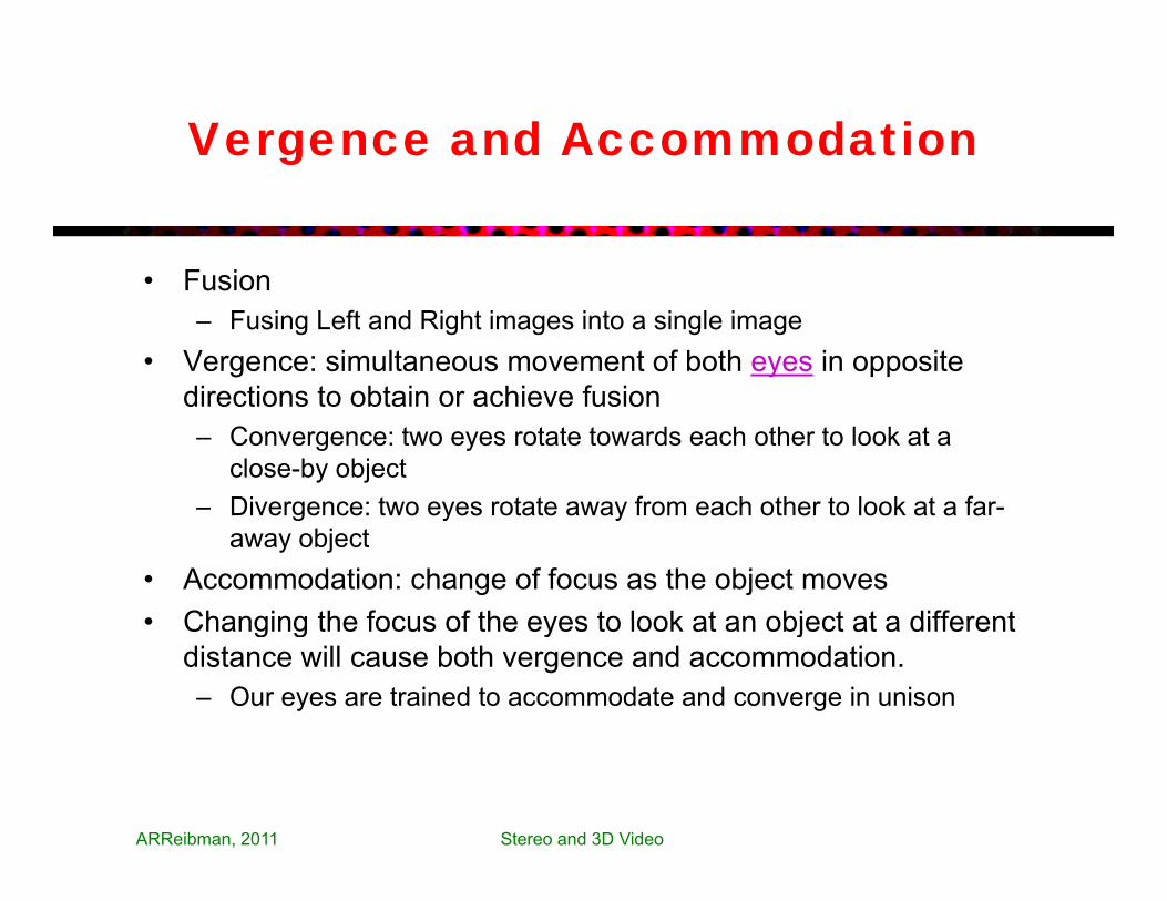
Vergence and Accommodation
• Fusion• Fusion– Fusing Left and Right images into a single image
• Vergence: simultaneous movement of both eyes in opposite directions to obtain or achieve fusiondirections to obtain or achieve fusion– Convergence: two eyes rotate towards each other to look at a
close-by object– Divergence: two eyes rotate away from each other to look at a far-– Divergence: two eyes rotate away from each other to look at a far-
away object• Accommodation: change of focus as the object moves • Changing the focus of the eyes to look at an object at a different• Changing the focus of the eyes to look at an object at a different
distance will cause both vergence and accommodation.– Our eyes are trained to accommodate and converge in unison
ARReibman, 2011 Stereo and 3D Video

Fusion and fusing image pairs
• Fusion occurs where L and R images “match”• Fusion occurs where L and R images match sufficiently– Fusion may not occur at all pixels
• Fusion depends on vergence– Hold up a finger and look in distanceHold up a finger and look in distance… – Humans are constantly adapting their two views (verging
and accommodating)
• Fusing objects can be tiring, even in real life– If they have rapidly changing depth– If they are very near
ARReibman, 2011 Stereo and 3D Video

Horopter and Panum’s fusional area
The horopter are the pointsp pin 3D space which project tocorresponding images pointson the retina, for a givenconvergence angle βconvergence angle, β.
When our eyes are converged,we can also fuse image pointsβ we can also fuse image points not on the horopter.Points outside Panum’s fusional area are not fused and createdouble images.
These regions are determined experimentallyand depend on the convergence angle/distance.
ARReibman, 2011 Stereo and 3D Video 32
When creating and displaying a stereo video, the design should avoid objects outside the Panum’s area, to reduce eye fatigue!

Horopter and Panum’s fusional area
The near (green line) and far (red line) borders of the fusion area around the fixation point (blue line).
Figure from Robert King, AT&T 2/2/2010

More on binocular fusion
• Lots of psychology literature on fusion• Lots of psychology literature on fusion– Hubel and Wiesel discovered binocular cells in the primary visual
cortex in 1959– Fusion is based on information in independent spatial-frequencyFusion is based on information in independent spatial frequency
channels– Wheatstone: can fuse two objects of different sizes!!– Julesz: can fuse random-dot stereograms (no monocular cues)Ju es ca use a do dot ste eog a s ( o o ocu a cues)
• Factors that limit fuse-ability– Blurriness, spatial impairments, spatial aliasing, brightness– Conflicting fusion (multiple possible vergences)Conflicting fusion (multiple possible vergences)
• Regular HF pattern over a bland LF background• A nearly-see-thru pattern on glass• Ambiguous figures & optical illusions
ARReibman, 2011 Stereo and 3D Video

Some Related Perception Phenomena
• Binocular rivalry and suppression• Binocular rivalry and suppression• Wallpaper stereo• Eye dominance
ARReibman, 2011 Stereo and 3D Video 35

Binocular rivalry and suppression
Binocular rivalryBrain swaps between each eye’s images
Binocular suppressionBrain sees only one of the two eye’sof the two eye s images
ARReibman, 2011 Stereo and 3D Video
What do you see when you try to fuse the two images in each row together?

Binocular rivalry and suppression
ARReibman, 2011 Stereo and 3D Video

Wallpaper Autostereogram
From: http://en.wikipedia.org/wiki/Autostereogram Stereo and 3D Video 38

Wallpaper Stereo
• When viewed with proper vergence the repeating patterns in a• When viewed with proper vergence, the repeating patterns in a wall paper appear to float above or below the background.
• When the brain is presented with a repeating pattern like wallpaper it has difficulty matching the two eyes' viewslike wallpaper, it has difficulty matching the two eyes views accurately. By looking at a horizontally repeating pattern, but converging the two eyes at a point behind the pattern, it is possible to trick the brain into matching one element of thepossible to trick the brain into matching one element of the pattern, as seen by the left eye, with another (similar looking) element, beside the first, as seen by the right eye. With the typical wall-eyed viewing, this gives the illusion of a plane yp y g g pbearing the same pattern but located behind the real wall. The distance at which this plane lies behind the wall depends only on the spacing between identical elements.
http://en.wikipedia.org/wiki/AutostereogramStereo and 3D Video 39

Eye Dominance
• Eye dominance: the tendency to prefer visual input from• Eye dominance: the tendency to prefer visual input from one eye to the other.
Th Mil t t Th b t d b th b i b th• The Miles test. The observer extends both arms, brings both hands together to create a small opening, then with both eyes open views a distant object through the opening. The observer then alternates closing the eyes or slowly draws opening back tothen alternates closing the eyes or slowly draws opening back to the head to determine which eye is viewing the object (i.e. the dominant eye)
• Approximately two-thirds of the population is right-eye dominant• Approximately two-thirds of the population is right-eye dominant and one-third left-eye dominant; however in a small portion of the population neither eye is dominant.
• Eye dominance does not affect stereopsis!
Yao Wang Stereo and 3D Video 40

Problems in Stereo Display
• Depth plane quantization• Depth plane quantization• Impact of viewer position• Impact of screen size
ARReibman, 2011 Stereo and 3D Video 41

Depth-plane Quantization Due to PixelizationPixelization
ARReibman, 2011 Stereo and 3D Video
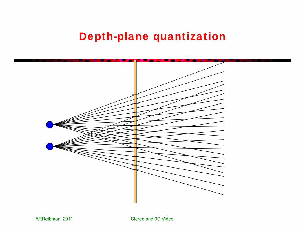
Depth-plane quantization
ARReibman, 2011 Stereo and 3D Video

Depth-plane quantization
ARReibman, 2011 Stereo and 3D Video

Depth-plane quantization
ARReibman, 2011 Stereo and 3D Video

Depth-plane quantization
Voxel
ARReibman, 2011 Stereo and 3D Video

Depth-plane quantization
Large distancea ge d sta cebetween depthplanes behindscreen
Resolvestimuli atdifferentdepths:~ 2 seconds~ 2 seconds
of arc
ARReibman, 2011 Stereo and 3D Video

Impact of viewer location

Viewer location: center, closer60
80Viewer location: center, closer
20
40Screen: 50Center view
0
20
-40
-20
-60
0 20 40 60 80 100 120 140 160 180 200
-80
ARReibman, 2011 Stereo and 3D Video

Viewer location: side, closer60
80Viewer location: side, closer
20
40Screen: 50Side view
0
20
-40
-20
-60
0 20 40 60 80 100 120 140 160 180 200
-80
ARReibman, 2011 Stereo and 3D Video

Viewer location: side, farther60
80Viewer location: side, farther
20
40Screen: 100Side view
0
20
-40
-20
-60
0 20 40 60 80 100 120 140 160 180 200
-80
ARReibman, 2011 Stereo and 3D Video

Viewer location: center, farther60
80Viewer location: center, farther
20
40Screen: 100Center view
0
20
-40
-20
-60
0 20 40 60 80 100 120 140 160 180 200
-80
ARReibman, 2011 Stereo and 3D Video

Viewer location: center, closer60
80Viewer location: center, closer
20
40Screen: 50Center view
0
20
-40
-20
-60
0 20 40 60 80 100 120 140 160 180 200
-80
ARReibman, 2011 Stereo and 3D Video

Screen geometry
• Each technology has its own screen size and resolution• Each technology has its own screen size and resolution
• IMAX48 f t 2048 1080 t ti 1 4– 48-foot screen; 2048x1080: aspect ratio 1.4
– Typically all seats are within one screen height
R l D XLS• Real-D XLS:– 20-foot screen; 2048x858 per view; aspect ratio 1.85– Typically seats are within {single digit} screen heights
• Home TV – Typically 8 feet viewing distance
• Screen parallax (i.e. disparity) is affected by the size of the display screen
ARReibman, 2011 Stereo and 3D Video

Mismatch in screen sizes and viewing distances
(movie theater vs. home)
R l lif Same screen angle, smaller disparity.Result: different object size and distance
Real-life,and originalintended screen size:
Objects appear to be in a puppet theater:be in a puppet theater:small and close together
ARReibman, 2011 Stereo and 3D Video

Adaptation of disparity for different screen sizesscreen sizes
R l lifReal-life,and originalscreen size:
One way to “fix”:Shift one imagerelative to the other
Same screen angle,hift d di it
Now, the object appears thecorrect size. However, objects
relative to the other
shifted disparity.Result: same object size
are almost always behind the screen. Causing conflict of converging and accommodation
ARReibman, 2011 Stereo and 3D Video

Horopter and Panum’s fusional area
The near (green line) and far (red line) borders of the fusion area around the fixation point (blue line).
Objects behindthe screen canbe tiring, due togaccommodationconvergencemismatch
Figure from Robert King, AT&T 2/2/2010

Different screen sizes
BUT, this isn’t valid witha different screen distanceSame screen angle,
hift d di it or an offset viewer. Need to use Intermediate View Synthesis.
ARReibman, 2011 Stereo and 3D Video
shifted disparity.Result: same object size

Depth-based adaptation of 3D content
• Screen parallax is affected by the size of the screen• Screen parallax is affected by the size of the screen
• To display for different screens, adjust stereo disparity• Limit maximum disparity to avoid too much eye strain
• Shifting/offsetting one image has only limited successg g g y
• Ideally, for a given viewer distance and viewer location, generate an intermediate view for that viewer:generate an intermediate view for that viewer:Intermediate view synthesis
ARReibman, 2011 Stereo and 3D Video 59

Display of Stereo Images/Sequences
• Principle:Principle: – Project images for the left and right eyes simultaneously in a way
that the two images can be received separately by left and right eyes
• Separation mechanism in stereoscopic display– Color filter (Cannot be used for display color stereo images)– Polorization
I t l i ti th l ft d i ht i (St hi I )– Interlace in time the left and right views (Stereographics, Inc.)– Viewers need to wear special glasses
• Auto-stereoscopic displayPresent two or multiple views on the same screen simultaneously– Present two or multiple views on the same screen simultaneously
– A viewer sees different view when looking from different angle– Viewers do not need to wear glasses– Autostereoscopic lenticular screens
©Yao Wang, 2007 Stereo Sequence Processing 60
Autostereoscopic lenticular screens

Using glasses
• Anaglyph. Two-color g yseparation of left/right view. Poor color rendition.
• Polarized. For viewing stereo gpairs projected through suitable polarizing filters. Better image quality.g q y
• Shutter glasses. Liquid crystal. Expensive. Require high refresh rate. Requirehigh refresh rate. Require synchronization of display and glasses
Page 61

Autostereoscopic display principle
– Blue pixels in pixel array display left view; Red display right view.p p y p y ; p y g– Parallax barrier or lens array allows left eye to see `left pixels’ and right
eye to see `right pixels’.– Thus separate views are presented to left and right eye creating illusion
Page 62
of depth.

3D-ready consumer TVs
• Display stereo pairs in time sequential manner• Display stereo pairs in time-sequential manner• Active shutter glasses
• Options– 3D DLP technology from TI (Samsung & Mitsubishi)– 3D plasma (Samsung)
Stereo and 3D Video 63

3D Video Delivery Formats①
⑦
+ Depth map②
③
⑦
⑧③
④
⑧
⑨
⑤
⑨
⑥
JBoyce, 2011
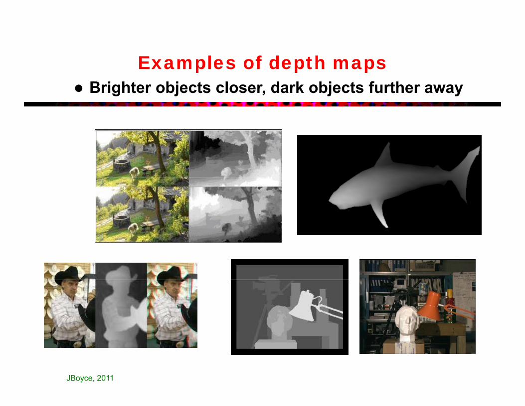
Examples of depth maps Brighter objects closer, dark objects further away
JBoyce, 2011

Coding of Stereo Sequences
• Simulcast:• Simulcast:– Code each view independently
• Extension from block-based hybrid code:C d i i t d d id d i MCP b t– Code one view using a standard video coder, using MCP between successive frames in this view
– Code the other view by using both DCP between views at the same frame and MCP in the same viewframe and MCP in the same view
– MPEG-2 Multiview profile• Mixed resolution
Code one view at the desired spatial/temporal resolution– Code one view at the desired spatial/temporal resolution– Code another view with reduced spatial/temporal resolution
• More advanced, object-based approach
©Yao Wang, 2007 Stereo Sequence Processing 66

MPEG-2 Multiview Profile
• Left view: MCP only• Right view: combination of MCP and DCP using the bi-directional prediction mode• Right view: combination of MCP and DCP, using the bi-directional prediction mode• Can be implemented using the temporal scalability tool:
• left view treated as the base-layer, right view treated as the enhancement layer• Only limited gain over simulcast
• MCP is typically more effective than DCP
©Yao Wang, 2007 Stereo Sequence Processing 67
MCP is typically more effective than DCP• Ineffectiveness of DCP due to inaccuracy of block-based constant disparity model

H.264 Multiview prediction structures
ARReibman, 2011 Stereo and 3D Video 68

Barriers to mass market
• Data and delivery format• Data and delivery format• Quality of 3D video production
– Content creators must be aware of 3D videographyg p y– Re-purposing of 3D content from cinema into the homes
• Human factorsSt i l f– Stereoscopic glasses are no fun
– Auto-stereoscopic has its own issues– Avoid objectionable 3D effects
ARReibman, 2011 Stereo and 3D Video 69

Additional perceptual issues
• Both too much depth and too many fast changes of depth cause• Both too much depth and too many fast changes of depth cause visual fatigue
• Conflicting depth information causes visual fatigue• Conflicting depth information causes visual fatigue– Accommodation and vergence are linked when scanning the scene
(but can be decoupled over time)– Compression aliasing other impairments (like keystoning) canCompression, aliasing, other impairments (like keystoning) can
make fusing more difficult– Screen or glasses scratch or dust
• Cross-talk– Left eye sees some of what Right eye should see– Stronger in high-contrast and large-disparity areasg g g p y– (But fusing is easier in high-contrast areas)
ARReibman, 2011 Stereo and 3D Video

Summary
• Human perception of depthHuman perception of depth• Principle in stereo imaging:
– Relation between depth and disparity for parallel set-up and other more general camera set-ups.E i l t i t f bit t– Epipolar constraint for an arbitrary set-up
• Disparity estimation: – Formulation as an optimization problem similar to motion estimation– Block-based approachpp– Mesh-based approach: regular mesh vs. adaptive mesh– Dynamic programming: not required– Joint motion and structure estimation: not required
• Intermediate view synthesis• Intermediate view synthesis• Stereo sequence coding
– Extension from standard video coder: Joint MCP and DCP– Simulcast with mixed resolution
©Yao Wang, 2007 Stereo Sequence Processing 71
• Stereo image/video display

Homework
• Reading assignment: Chap 12• Reading assignment: Chap. 12• Written assignment
– Prob. 12.1P b 12 2– Prob. 12.2
©Yao Wang, 2007 Stereo Sequence Processing 72

Additional references
• A Woods T Docherty and R Koch “Image distortions in• A. Woods, T. Docherty, and R. Koch, Image distortions in stereoscopic video systems”, Proceedings SPIE Stereoscopic Displays and Applications IV, vol. 1915, San Jose, CA, Feb. 1993.1993.
ARReibman, 2011 Stereo and 3D Video 73