Embed Size (px)
Citation preview

Bioinspir. Biomim. 10 (2015) 035001 doi:10.1088/1748-3190/10/3/035001
PAPER
Stereotypical reachingmovements of the octopus involve both bendpropagation and arm elongation
SHanassy1, ABotvinnik1, T Flash2 andBHochner1
1 Department ofNeurobiology, Silberman Institute of Life Sciences and the Interdisciplinary Center forNeural Computation,HebrewUniversity, Jerusalem, Israel
2 Department of Computer Science andAppliedMathematics,Weizmann Institute of Science, Rehovot, Israel
E-mail: [email protected]
Keywords: neuromuscular system, muscular hydrostat, octopus, invertebrate, motor control, hyper-redundant appendages, reachingmovement
AbstractThe bend propagation involved in the stereotypical reachingmovement of the octopus armhas beenextensively studied.While these studies have analyzed the kinematics of bend propagation along thearmduring its extension, possible length changes have been ignored. Here, the elongation profiles ofthe reachingmovements ofOctopus vulgariswere assessed using three-dimensional reconstructions.The analysis revealed that, in addition to bend propagation, arm extensionmovements involveelongation of the proximal part of the arm, i.e., the section from the base of the arm to the propagatingbend. The elongations are quite substantial and highly variable, ranging from an average strain alongthe armof−0.12 (i.e. shortening) up to 1.8 at the end of themovement (0.57 ± 0.41, n= 64movements, four animals). Less variability was discovered in an additional set of experiments onreachingmovements (0.64 ± 0.28, n= 30movements, two animals), where target and octopuspositionswere keptmore stationary. Visual observation and subsequent kinematic analysis suggestthat the reachingmovements can be broadly segregated into two groups. Thefirst group involves bendpropagation beginning at the base of the arm and propagating towards the arm tip. In the second, thebend is formed or presentmore distally and reaching is achievedmainly by elongation andstraightening of the segment proximal to the bend.Only in the second type ofmovements iselongation significantly positively correlatedwith the distance of the bend from the target.We suggestthat reaching towards a target is generated by a combination of both propagation of a bend along thearm and arm elongation. These twomotor primitivesmay be combined to create a broad spectrumofreachingmovements. The dynamicalmodel, which recapitulates the biomechanics of the octopusmuscular hydrostatic arm, suggests that achieving the observed elongation requires an extremely lowratio of longitudinal to transversemuscle force (<0.0016 for an average strain along the armof around0.5). This was not observed andmoreover such extremely low value does not seem to bephysiologically possible. Hence the assumptionsmade in applying the dynamicmodel to behaviorssuch as static arm stiffening that leads to arm extension through bend propagation and the patterns ofactivation used to simulate such behaviors should bemodified to account formovements combiningbend propagation and arm elongation.
Introduction
Octopuses and their relatives, squids and cuttlefish,belong to the group of modern Cephalopoda(Coleoidea), whose eight flexible arms are uniqueamong mollusks (Hochner 2012). These constitute ahighly redundant biomechanical structure which has
virtually an infinite number of degrees of freedom(DOF). The adaptability, dexterity and maneuver-ability of octopus arms have attracted considerableattention from robotic engineers as source ofinspiration for designing and constructing a newclass of flexible robotic arms (Hochner 2012, Mar-gheri et al 2012).
RECEIVED
23 June 2014
REVISED
13 January 2015
ACCEPTED FOR PUBLICATION
15 January 2015
PUBLISHED
13May 2015
© 2015 IOPPublishing Ltd

The octopus arm is a‘muscular hydrostat’ (MH),belonging to a group of organs lacking skeletal supportand almost entirely comprised of muscle cells. In suchstructures themuscle itself is responsible for both sup-port and movement (like the tongues of many terres-trial vertebrates, the appendages of cephalopodmollusks and the elephant trunk (Kier and Kath-leen 1985)). The most important biomechanical fea-ture of the MH is that it maintains a constant volume,since muscle cells are composed primarily of an aqu-eous liquid, which is practically incompressible at phy-siological pressure (Kier and Kathleen 1985). Instructures that maintain a constant volume, anychange in one dimension causes a compensatorychange in at least one other dimension. In the octopusarm, the typical MH structure consists of a denselypacked three-dimensional (3D) arrangement of mus-cle fibers (transverse muscle fibers, longitudinal mus-cle fibers, helical or oblique muscle fibers) andconnective tissue fibers surrounding a central axialnerve cord (figure 1;(Kier and Stella 2007, Feinsteinet al 2011)).
Octopusmovements (in the article we use the term‘movement’ to describe a set of motions that are rela-ted to behavior like reaching movement and fetchingmovement) may be highly localized, as in searchingmovements, or may involve the entire length of thearm, for example in goal-directed movements likereaching (Gutfreund et al 1996) and fetching (Sumbreet al 2006). Therefore octopus arm movements pro-vide an outstanding example of efficient movement
control of a hyperredundant structure. Hyperre-dundancy makes the inverse kinematics a very com-plex process (Bizzi et al 1991, Flanders andHermann 1992). Ignoring length changes, intensiveanalysis of the octopus’ reaching and fetching move-ments has shown that the octopus uses a stereotypicalbehavior. For example, stereotypical reaching is deter-mined practically by three parameters, namely, pitch,yaw and the velocity of the bend point propagation (apoint of maximal curvature along the arm), while ingeneral the arm has an infinite number of DOF (Gut-freund et al 1996, 1998). This dramatically simplifiesthemotor control of a hyperredundantMH.
Previous work has shown that in the reachingmovement a bend is formed somewhere along the armand is then propagated toward the tip. In this stereo-typical behavior the bend in the arm serves as the con-trolled end–effector (similar to our hand). This pointhas the highest curvature along the arm and thereforecould be easily detected (Gutfreund et al 1996, Gut-freund et al 2006). Similar bend propagation is foundin other behaviors involving arm extension, a termwhich was originally used in Gutfreund et al (2006) todescribe a fundamental component in various beha-viors of octopus, such as locomotion, searching, andreaching toward a target. In all of those cases, the armis extended in what seems to be a stereotyped androbust pattern.
The kinematics of reaching movements were eval-uated by measuring the trajectories of the maximalcurvature of a propagating bend (bend point). Thebend tends to move within a single plane in a simple,slightly curved path connecting the center of the ani-mal’s body with the target location. This behavior isobserved in spontaneous unconstrained movementsand in goal-directed movements. Normalizing thevelocity (v(t)) profiles and the time (t) according to themaximum velocity (vmax) and the distance (d) traveledby the bend revealed an invariant velocity profile of thebend point associated with the acceleration phase ofthe reaching. Here, the term ‘invariant’ refers to theshape of the velocity profile which looks similar inmost of the reaching movements when the velocity isnormalized with respect to duration and maximalvelocity (see appendix A.1, Gutfreund et al 1996).
Arm extension comprises three phases, an initia-tion phase prior to extension, an invariant mono-tonically increasing extension phase and a thirddescending phase corresponding to the end of themovement (see figure 4; appendix A.1). These phaseswere interpreted as indicating the existence of aninvariant motor program scaled for each movement(Gutfreund et al 1996). The inverse dynamics of reach-ing movement was studied by correlating the kine-matic parameters with EMG recordings. This showedthat the motor program for reaching has feed-forwardcharacteristics (Gutfreund et al 1998, 2006, Sum-bre 2004). Moreover, it was found that the motor pro-gram is embedded in the neuromuscular system of the
Figure 1.Transverse section of the armofOctopus vulgaris showingthemajor components of the intrinsic armmusculature. Theintrinsicmusculature of the arm is an array of densely packedmuscle fibers organized in threemain directions: longitudinalfibers (L), transverse fibers (T), and oblique fibers (O). N,axial nerve cord in the center of the arm; SRM,muscles of thesucking rings on the ventral side. Dorsal side is up. Repro-ducedwith permission fromGutfreund et al (1998).
2
Bioinspir. Biomim. 10 (2015) 035001 SHanassy et al

arsm, since it is possible to induce extension move-ment in arms whose connection with the central brainhas been severed (Sumbre et al 2001a, 2001b).
Because bend propagation along the arm is themain characteristic of arm extension, this feature wasused as an end-point in defining reaching movements(for example, distinguishing between extension andsickle-like or opening movements where the benddoes not propagate far along the arm; (Sumbreet al 2001a, 2001b, Yekutieli et al 2005a, 2005b). Awave of muscle activation propagating along the armto create stiffening that pushes the bend forward wassuggested as a simple mechanism to explain armextension. When this idea was tested in a dynamicalmodel of the octopus arm, the natural behavior couldbe replicated (Yekutieli et al 2005a, 2005b).
For simplicity and because of biological plausi-bility, it was assumed that similar activation of allmus-cle groups of the arm causes stiffening withoutchanging the arm shape (length/width) due to con-stant volume constraint (Yekutieli et al 2005a, 2005b,Matzner et al 2000, Feinstein et al 2011). However,arm length was not measured in these studies, pre-venting testing whether arm extension is also medi-ated by changing the arm length. When inserting anarm into a tube octopuses can elongate their arms 70%from rest length (Margheri et al 2011, Mazzolaiet al 2013). Therefore, in the current study we devel-oped and used a 3D reconstruction technique for ana-lyzing the reachingmovements of theOctopus vulgaris.This allowed measuring the kinematics of lengthchanges involving arm extension movements togetherwith the kinematics of the bend point. The results sug-gest that reaching movements are achieved throughvariable combinations of bend propagation and armelongation. We attempted to correlate these twomotions to more accurately define the mechanisms ofarm extension.
Materials andmethods
The experimental animalsSpecimens of Octopus vulgaris were caught off theMediterranean shore by local fishermen. The animalswere maintained in 50× 40× 40 cm tanks containingartificial seawater. This was continuously circulated ina closed system through a biological filter of Orlon,gravel and coral dust and protein skimmer. Watertemperature was held at 17–19 °C in a 12 h light/darkcycle. Four animals weighing 200, 200, 450 and 470 gwere used for this study. The data of one of the animals(Octopus A, 470 g) was taken from a previous experi-ment (Sumbre 2004, unpublished data) carried out inthe same experimental environment.
Prior to the video recording sessions, the animalswere moved to a larger glass tank (80 × 80 × 60 cm)with a water temperature of 18 °C, except for OctopusS (200 g) which was recorded in the same smaller tank
in which it was maintained. Video recordings beganonly after the animals were well acclimatized to thenew tank after several days.
The behavioral task and video recordingsThe task started when a target, a green disk of 2 cmdiameter or a dummy crab, both with a small weightattached (figure 5, green circle), was lowered into thewater. The target was moved slightly to attract theoctopus’ attention. The octopus either extended oneor more arms or swam towards the target. Every fewtrials the animal was rewarded with a piece of shrimpmeat, not attached to the target, as in Pavlovianclassical conditioning.
Two digital video DV cameras (Panasonic AG-DVC30E camcorder) recorded the octopus armmovements. The cameras viewed the subject from thesame aquarium face but with an angle of 50–60°between the principal rays, as suggested by Yekutieliet al (2007). Shutter speed of both cameras was set to1/120. The PAL S-VHS video system was used, allow-ing a temporal resolution of 20 ms between adjacentimages. To achieve this resolution, we used the PALvideo system at 25 frames/s with image resolution of720 × 576. Each frame is composed of two interlacedfields (half images that are composed either of the oddhorizontal lines or the even horizontal lines). Afterretrieving the two fields, each was interpolated into afull-sized frame, achieving time resolution of 50 ima-ges/s. The data were later downloaded to a standardPC computer using Adobe Premier (1.5) software anda FireWire connection (IEEE 1394).
Trials in which the octopus extended its arm/stoward the target were termed ‘successful trials’,regardless of whether it actually touched the target.Successive video images of successful trials were cap-tured from both cameras, digitized with the AdobePremiere environment and saved on hard disk.
The computer environment for 3D reconstructionand analysis of octopus armmovementsA dedicated computer program was developed tomanage and instantly create a database of movementreconstructions and analysis results from movementscaptured on video files. Using this system, 64 of 71reaching movements were successfully reconstructed.This computer program, developed using Matlab(version 7.1), implements the previously developedmethods for reconstruction of the 3D backbonescurves of octopus arms in motion described in detailin Yekutieli et al (2007) with some further improve-ments. We now briefly describe the process ofreconstruction and consider severalmain issues.
Similarly to Yekutieli et al (2007) the system wedeveloped takes the following steps to achievereconstruction
• camera synchronization
3
Bioinspir. Biomim. 10 (2015) 035001 SHanassy et al
• camera calibration
• movement recording using two cameras in a stereoconfiguration
• for each video frame, themethod involves:
(1)manual (by eye) tracking of amarked starting pointalong the arm instead of automatic registration asdescribed infigure 3.6 in Yekutieli et al (2007).
(2)Manual tracking of the contour of the arms frombase to tip in the two views.
(3)Automatic extraction of the two-dimensional (2D)midline (the backbone) of each contour.
(4)Temporal and spatial spline smoothing of theresults separately for each view point (a new featureadded here).
(5)Matching the two 2D midlines using epipolargeometry.
(6)3D reconstruction.
(7)Manual correction using spline interpolation ofbad 3D reconstructed regions.
(8)Temporal and spatial spline smoothing of the 3Dreconstructed results (a new feature added here).
After camera synchronization the times for bothviewpoints were synchronized. In the second step ofthe algorithm, the direct linear transformation matri-ces representing themodel for the camera’s projectionfrom 3D space onto 2D images were calculated sepa-rately for each camera. This was achieved using themarkings (by eye) and the predetermined calibrationmodel in the calibration process described below.
We used the same simple pinhole camera modelcommonly used in computer vision for perspectiveprojection as described in Yekutieli et al (2007). Eachcamera had 11 parameters defining its position andorientation, as well as optical characteristics, such asfocal length, x–y ratio, and image center.
The following notation is used throughout. Usinghomogeneous coordinates, a 3D point q is representedby (x, y, z, 1)T and a 2D point p by (x, y, 1)T. A 2D linesatisfying the equation ax+ by+ c= 0 is described bythe vector that includes its parameters (a, b, c)T. A 3Dpoint q is projected onto a 2D point p on the imageplane by the projection equation
=p Mq. (1)
The camera projection matrix M is a 3 × 4 matrixdefined up to a scale factor. The elements ofM are the11 parameters of the pinhole cameramodel.
Calibration is the process of determining these 11parameters for each camera. First, both cameras recor-ded a 3D object with known geometry—the calibra-tion cube. This object must have at least six points thatare clearly visible and detectable at the two views.
Then, the 2D position of each of these points wasmarked in each view by eye. A least-square procedureestimated the camera parameters so that the viewed2D points fitted the known 3D geometry (Abdel-Azizand Karara 1971, Cipolla and Giblin 2000). The cali-bration frame was that used by Yekutieli et al (2007).Marking was manual with subpixel precision using adedicated graphical user interface (GUI). Before cali-bration, the relative position of the center of eachwhite dot should be known with submillimeter preci-sion. These data for the calibration body wereobtained from Yekutieli et al (2007). After calibration,it is possible to reconstruct the position of a 3D pointfrom its projections using the direct linear transform(DLT) procedure (Yekutieli et al 2007). The space thatthe calibration frame occupies is referred to as the cali-brated space and points outside this space have higherreconstruction errors. Therefore, to find the projec-tion matrices of the two cameras images as describedabove, a calibration body was introduced and movedin the areawhere the behavior took place.
To reconstruct the movements, successive videoframes of reaching movements were digitized and dis-played in the system GUI. For each reaching move-ment the beginning of the movement was defined asthe time at which the generated bend in the extendedarm started to move in space, and the end was deter-mined by the time the bend reached the target or thearm stoppedmoving.
To reconstruct the backbone curve (BBC) at eachtime frame, the contours of the arm were manuallylabeled and digitized and the 2D midlines were auto-matically extracted. Errors in length measurementsare highly affected by errors in the alignment processbetween BBC indexes at different times. To reducesuch errors we relied on a manual alignment of thefirst marking points. This could, for example, be asucker close to the base of the arm or an obvious pat-tern, which could be seen clearly on the two views dur-ing the entire duration of themovement.
From the pair of 2D midlines, a 3D BBC wasreconstructed using the DLT algorithm. During thisprocess the cubic spline-smoothing method (CSS,appendix A.3) was separately applied to 2D and 3Dreconstructed curves to reduce the spatial noise. Inaddition, temporal noise was smoothed by applyingthe CSS method to data points of matching indexes,assuming that the interval between two consecutiveframeswas short enough and therefore the local lengthchange (i.e., the distance between two adjacent datapoints) between two frames pairs i and i+ 1I was rela-tively small, ∼2–∼5 mm (figure 2 gives an example ofsmoothing results applied to the 2D marked curves).For temporal smoothing, the reconstructed BBC weredivided into 200 equal length segments separated bypoints and for each point an index was given whichwas used for applying theCSSmethod over time.
The reconstructed and smoothed 3D midlineswere inspected by eye using the dedicated interface.
4
Bioinspir. Biomim. 10 (2015) 035001 SHanassy et al

Figure 2.The spline smoothingmethod. (A)–(B) Example of smoothed single curves using the spline smoothingmethod on 2Dmarkedcurves for the left (A) and right view points (B). The originalmarking results are given by the black dotted curve, the red curve showsthe results of applying spline smoothing to the dotted curve, the green line shows the curve after applying the smoothingmethod to allcurves over time. (C)–(D)An example of consecutivemidlinesmarked in a singlemovement. (E)–(F) Results of the spline smoothingmethod applied separately to each consecutive curve. Colorsmark the data points from (C)–(D) that were smoothed together usingthe spline smoothingmethod (i.e., along the curves). (G)–(H) Results of the spline smoothingmethod applied to the curves over time.Colorsmark the data points from (E)–(F) that were smoothed together using the spline smoothingmethod (i.e., over time), and thecurves which the spline curves approximated. (A),(C), (E) and (G) show the left POVand (B), (D), (F) and (H) the right POV.
5
Bioinspir. Biomim. 10 (2015) 035001 SHanassy et al

Movement sequences containing too many errors(more than 8% of unreconstructed frames or a timedomain longer than three frames) were excluded fromfurther analysis (seven movements). In the remainingmovements with only short error sequences in datapoints or mistakes in reconstruction (not more then8%), CSS was used to interpolate the erroneoussection. To maintain uniform continuation of thecurves, CSS was applied to the whole 3D sequenceagain after the interpolation.
The trajectory of the bend point position in spacewas reconstructed directly from the markings of thebend point by eye, in successive video frames, as twopoint of view (POV) pairs, in 2D using the DLT algo-rithm. These points were determined, by eye, as thepoint of intersection of the bend-point propagatingtrajectory (estimated from the points of maximal cur-vature in adjacent frames) and the reconstructed armmidline (figure 5(B)) and were marked manually,recorded and stored. While reaching movement couldinvolve body motion toward the target, rotation of thebody was negligible, therefore, to correct for wholebody movements, the origin of the coordinate systemwas fixed at one of the animal’s eyes, which has a fixedposition in the octopus body, and was marked manu-ally with the mouse cursor. The coordinates of thispoints were also recorded.
Similar to the procedure used by (Gutfreundet al 1996), these data were used for the analysis of thekinematic features of the bend point motion using theDLT algorithm. From this set of data the trajectory ofthe bend point relative to one of the eyes was thenderived through vector subtraction of the eye 3D loca-tion coordinate’s vector from those of the bend pointlocation coordinates’ vector. Thus, the trajectory ofthe bend-point in space was defined in a coordinatesystem relative to the animal’s body. The data werefirst smoothed by applying a CSS (see above andappendix A.3) to the reconstructed 3Dpoints on the x-axis, y-axis and z-axis as a function of time. The tan-gential velocity of the bend point propagation in 3Dwas calculated from the derivatives of the smoothed
q= (x, y, z, 1)T coordinates, i.e., v= ̇ + ̇ + ̇x y z .2 2 2
We could thus measure the 3D trajectories of the bendpointmotion in space.
Finally, the positions of the suckers along thereconstructed midlines were estimated in four move-ments by projecting the 2D position of manuallylabeled suckers onto the 3D reconstructed midlinesusing the DLT method. This was achieved technicallyby intersecting the 3D line satisfying the linearequation ax+ by+ cz+ d= 0, described by the vectorthat includes its parameters r= (a, b, c, d)T whichrefers to the principle ray of the projection from 3Dspace to a 2D point p marked on each sucker point,extracted from the DLT model and the 3D recon-structedmidline backbone, i.e., by finding a point q onthe backbonewhich solved
′ =r q 0. (2)
We estimated q by choosing the point on the back-bonewhichminimized
′r q .
Arm length and elongation velocity profilesThe length of the arm was measured from thereconstructed 3D BBC. Each BBC was digitized intoexternal x y z coordinates indexed from the base of thearm to the tip, ensuring that incremental indexesindicated adjacent points along the arm. Consideringthat, the length of the arm was calculated from thecurves using:
∑= = + −l t i ix xlength( ) ( 1) ( ) , (3)t
i
t t
where +ix ( 1)t (i.e. bolded x) describes a vector (x, y,z)i with values of the external coordinates of theindexed backbone point sequence at time t with indexi along the BBC (0< i⩽ n, where n is the number ofpoints along the BBC, in which 0 denotes the first basepoint and n denotes the tip point. n= 200 points andtherefore there are 199 segments).
The elongation velocity was estimated using thediscrete estimation of the length derivative withrespect to time, denoted by:
ΔΔ
= =−Δ+
tl l l
ve( )t 0.02
,t t t t
where Δlt+ t is the length of the arm at the next interval,Δt= 0.02 s (the time resolution of the cameras) and t isamultiple ofΔt.
To measure the changes in length of the distal orproximal part of the arm at time interval t, we firstdetermined the bend location along the BBC by find-ing imin which minimized the Euclidean distancebetween its BBC coordinates and the bend point coor-dinates at time interval t:
= −{ }i ib xarg min ( ) , (4)i t tmin
where bt is an (x, y, z) external coordinate of the bendpoint at time tdetermined in the dedicated reconstruc-tion procedure described above. Since the Euclideandistance between two adjacent BBC index points wassmall compared to the total length of the arm, the errorusing thismethodwas negligible.
To acquire the elongation profile of the arm distalto the bend, the length of the distal part of the armwasmeasured with equation (3) using equation (4) todetermine the first index point of the distal part. Thesame procedure acquired the elongation profile of thesegment proximal to the bend.
The reconstruction and methods for measuringlengthwere testedwith different types of bent and flex-ible objects of lengths ranging from 5 to 50 cm. Thereconstruction length errors in all reconstructionswere negligible (below 4mm and 0.75% of the lengthof the reconstructed object). Figure 3 shows
6
Bioinspir. Biomim. 10 (2015) 035001 SHanassy et al

an example of a dummy arm used to test the methodfor length measurement. The reconstructed length ofthe dummy, in this example, was 43.69 ± 0.45 (mean ±SD; n= 14) and was significantly close (−0.31 cm) toits true length of 44 cm (p< 0.01; paired t-test;figure 3).
Appendix A.4 gives further information on theerror inmeasurement of arm lengthening.
The envelope of themovementmidlinesCreating the BBC envelope of the movement is a newgraphical method we developed to describe a whole3Dmovement pattern of an elongated organ in a singleimage. The trajectory, lengthening, velocity and otherimportant kinematic parameters could be visualizedusing a variety of colors and the shapes created by theenvelope. The envelope was created through a sam-pling function (Matlab’s grid data function), whichtook the midline backbone points as the sampled datapoint input and connected them to create a mesh orgrid of heights. The 3D form thus created was definedas the envelope of the movement. The BBC werecolored differently from the envelope andwere plottedover the envelopes. The plot was created by Meshgrid(Matlab function, figure 5(A)).
T-test andpaired t-testWe used Matlab’s function‘t-test’ for hypothesis test-ing on single samplemeans to compare elongation andother kinematics measurement values in differenttimes and conditions. Here the null hypothesis (meanis zero) was rejected if p< 0.05. A paired t-testcompared different pairs of values when the samplegroup had several values per observation. The paireddifference column of the two different value columnswas applied as the input for the Matlab function. Therejection criteria were as described for the single t-test.
Acomputerizedmodel of the octopus armTo predict the patterns of muscle activation under-lying arm elongation, simulations were carried outwith minor modifications on a model of the octopusarm described in detail in (Yekutieliet al 2005a, 2005b). In that article several experimentsand computational modeling were described in orderto explain the relevance of that model for the simula-tions of an octopus arm and its musculature. Briefly,the model arm is divided into 20 segments, eachsegment being composed of four point masses con-nected by a single system containing a spring and adamper in parallel, representing the muscles (twolongitudinal and one transverse; see figure 9 for severalarm model drawings). Several forces act on the pointmasses. Gravity and buoyancy act vertically. Waterdrag forces act in opposition to movement. Two typesof drag forces are considered—normal and the tan-gential drag. These forces, together with the massesand the acceleration, give rise to the equation ofmotion of the system. Accelerations were calculatedfrom the forces and the masses. Then, numericalintegrations were used to calculate the position of themasses based on their position in the previous timestep. The inputs to the model were the initial form ofthe arm and the type of activation of the muscles. Theresults were the variations in time of the arm’s form.
In the simulations, similarly to Yekutieli et al(2005a, 2005b), input to the model (analogous to aneural command) was changed by changing the acti-vation amplitude and the activation traveling time,keeping all other parameters fixed. The nonlinearmuscle model was used. Activation signals were bell-shaped with peak velocity of 5 cm s−1 and a fixed dura-tion of 1 s.
To produce the length changes here, instead of giv-ing the same activation amplitude to both transversaland longitudinal muscle types as in Yekutieli et al(2005a, 2005b), the activation amplitude wasmodifieddifferently for transverse and for longitudinal muscles
Figure 3.An example of a reconstruction of a dummy octopus arm. (A) The dummy arm straightened and placed beside a scale tomeasure its actual length, whichwas 44 cm. The dummy armwasmade of copperwirewrapped in paper and sealing plastic. A floatwas placed at the end and at the beginning of the dummy arm, so that the armwould ‘move’ (float) inwater without human touch. (B)One (minimized) frame example of the result ofmarking the dummy'smidline while itfloated upward. In theworking environmentthe user is able to slide between frames and points of views in order to obtain clearer point of view so therewill be no doubt in themarkings.
7
Bioinspir. Biomim. 10 (2015) 035001 SHanassy et al
to create different constant ratios between their activa-tion amplitude values and to examine the arm elonga-tion patterns generated due to these activations.
Results
Armelongation during natural reachingmovementsTo determine whether reaching movements by Octo-pus vulgaris involve changes in arm length agraph showing arm length during reachingwas createdfor 64 reaching movements (figure 5(D) red curve,
figures 6(A) and (B)). These graphs give the distribu-tion of ‘elongation profiles’ and showed that mostreaching movements were accompanied by arm elon-gation with an elongation average of 7.32 ± 4.34 cm(SD) (figure 6(D)). Avarage strain, along the arm, atthe end of the movement (the average end strain:ε= (lend− l0)/l0, where lend = end of movement armlength and l0 = initial arm length) ranged from −0.12(i.e., shortening) up to 1.8 with a mean of 0.57 ± 0.41(SD%) (figure 6(E)). The average end strain value andend elongation difference (lend− l0;‘elongation’ indi-cates net end elongation) were significantly positive(p= 2× 10⁻¹⁶, 2 × 10⁻²⁰ respectively, paired t-test;
A
C D
EF
B
Nor
mal
ized
vel
ocity
Nor
mal
ized
vel
ocity
N
orm
aliz
ed v
eloc
ity
Normalized time
Normalized timeNormalized time
Nor
mal
ized
vel
ocity
Normalized time
Varia
nce
210
0
2
-1-2
-2
1011
12
10
11
12
14
14
16
16
18
18
20
2022
22
24
24
zz
y
y
1
0.5
00
x
x
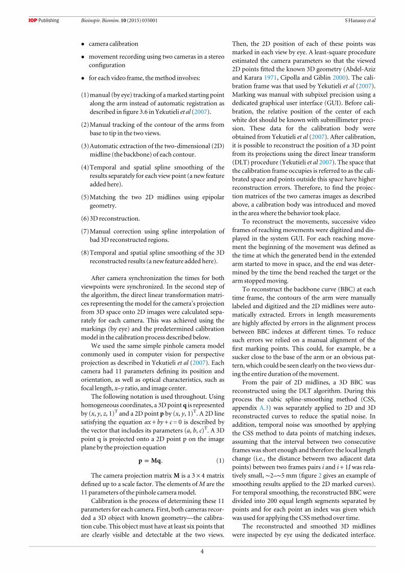
Figure 4.The typical behavior of the tangential velocity is similar to previous observations. The normalized velocity profiles in (A)werenormalized for velocity and distance and aligned at the peak. There is a substantial overlap during phase II. Data fromGutfreund et al(1996). A similar overlapwas observed in the profiles of 49 of themovementsmeasured here (B). Also similar were the behavior of themean (C) and variance (D) of the profiles. (E) The normalized elongation velocity profiles. (F) The stereotypical reconstructedtrajectory of themovement infigure 5. Greenmarks the preferred plane. The average distance of each point from the planewas0.32 cm.
8
Bioinspir. Biomim. 10 (2015) 035001 SHanassy et al

Figure 5.A reachingmovement involving elongation and its elongation profile. (A) The envelope of the 3Dbackbone of an octopusreachingmovement reconstructed from a sequence of images captured from two angles. From top to bottom, originalmovement,rotated 45° and 90° around the x-axis and 180° around the y-axis. (B) Snapshots from the right camera sequence. The red circleindicates the position of the bend pointmarking. (C) Themidlines projected onto the plane of bestfit of the reconstructedmidlines(average distance of 0.65 cmper dot). (D) Blue dotted curve—elongation velocity of the armduring themovement. The arrows in (A),(C) and (D),mark the time of thefirst twominimumpoints of the elongation graph. Thick red curve—elongation profile. The armextended from10.5 to 16.5 cmduring themovement (57% elongation relative to the initial length). Dotted green curve—bendpropagation velocity profile—its bell-shape is typical for reachingmovements. Solid cyan curve—distal shortening profile shows adecrease in the arm segment distal to the bend to almost zero, while the arm is still elongated, as shown by the red elongation curve.
9
Bioinspir. Biomim. 10 (2015) 035001 SHanassy et al

figures 6(B)–(E) and (G)). Thus, arm length wasmodulated during reaching movement and both bendpropagation and arm elongation determined thetrajectories of the bend point in reaching movements.As reaching movements involve substantial armelongation, reaching movement is not generated by asimple arm stiffening as previously suggested. That the
elongation is highly variable (82%–180%) suggeststhat arm elongation is controlled independently ofbend propagation.
In 43 of the 64 movements (67%), showed typicalproperties as reported for 70% of the movements inGutfreund et al (1996, figure 4). These included ste-reotypical behavior of the tangential velocity of
A B
C
FG
E
D
40
35
35
30
25
20
15
10
30
25
20
15
10
10 3020 40 50-100
0
30
25
20
15
10
50 1 2 3 4 5
time (sec)
Arm
leng
th (c
m)
5
Length (cm)
Paired difference between total bendtrajectory lenght and elongation (cm)
Mean:
mean: 0.5 0.41
mean: 7.32 4.336
Mean: 14.76 4.79
Mean: 22.08+5.75
14.54+ 8.91_
_Percents:36.59+ 22.96%p=1x10-19
Total elongation:Mean: 7.32 + 4.34
Bend trajectory length:
p<0.01
16
14
12
10
-10
8
6
4
2
0
1618
141210
86420
141210
86420
14
16
18
20
12
10
10 155 20 25 30
150 5-5 10 20
1.50 0.5-0.5 1 2 2.5
35 40
8
6
4
2
0
0 10 20 30 40 50
Length (cm)
Leng
th (c
m)
Elongation: Lend- L0 (cm)
LendL0End average strain: (Lend- L0)/L0
p<2x10-16
p<2x10-20
Lend:
L0:
_
Mean: 21.86 + 8.73 _
_
Figure 6.Octopuses elongate their arm during the reachingmovement. (A) Superimposed elongation profiles of all 64 reachingmovements. (B)Histograms of all initial arm lengths (L0, brownbars) and all end lengths (Lend, blue bars). (D) Their paireddifference (Lend–L0) andE the average strain value (Lend–L0)/L0) were significantly positive (t-test; p is given in the histograms). (C)Box-plots showing the distributions of initial and end arm lengths of all 64movements. The box has lines at the lower quartile,median, and upper quartile values. Barsmark themost extreme values within 1.5 times the inter-quartile range from the ends of thebox. Red crossmarks data with values beyond bars. (F)Histograms of total elongation and total length of the bend trajectoryjuxtaposed for 64 reachingmovements. Themean ± SDof the two histograms are given in the key for each histogram (G)Thehistogramof paired differences between the values of elongation for each arm segment and trajectory length in (A). The p values of thet-test are given.
10
Bioinspir. Biomim. 10 (2015) 035001 SHanassy et al

extension with an invariant second acceleration phaseand a planar linear trajectory of bend propagation(figure 4(F)). Themovements with a stereotypical armextension like that shown inGutfreund et al (1996) didnot show a stereotypical elongation profile. No com-mon shape was observed (figure 4(E)) with normal-ization of the bend propagation velocity profile as inGutfreund et al (1996) (see introduction andfigures 4(A)–(B)).
The origin of elongation along the armTo test whether the arm elongated proximally ordistally to the bend or, alternatively, whether armelongation occurred all along the arm, the arm wasdivided into two segments, one distal to the bend andone proximal to the bend, and their lengths measured(see methods ‘arm length and elongation velocityprofiles’ equation (4) for calculating imin). Total armelongation was then plotted against the length changesof the distal and proximal segments during 49 armextensionmovements inwhich the proximal anddistalsegments could be tracked during the entire move-ment. The elongation was highly positively correlatedwith the length changes in the proximal part(figures 8(C)–(F); p< 0.01). Thus, both elongationand bend propagation appear to involve changes in thelength of the proximal segment. Plotting the elonga-tion of the distal segment versus total elongation gave anegative rather than a positive slope (data not shown),showing that the distal part was shortened rather thanelongating, either due to the propagation of the bendor real shortening.
To refine our analysis we located the origins oflengthening by labeling specific suckers during severalmovements. Using our method, it was very difficult totrack the suckers’ positions during the whole move-ment, since in many movements the suckers weretemporarily hidden from the cameras’ view. We suc-ceeded in reconstructing sucker positions completelyonly in fourmovements (figure 7).
In all these movements the distance between adja-cent suckers close to the base increased during bendpropagation, while the distance between distal suckersremained constant. Pairs of suckers from close to themiddle of the arm to the tip preserved almost the samedistance during the movement or exhibited onlyminor length changes. This supports the elongationoccurring mostly in the proximal part of the reachingarm and that the strain is not uniform along the arm.
Contribution of elongation to bend extensionThe total arm elongation during reaching was com-pared with the overall length of the bend trajectory.The mean length of the bend trajectory was21.86 ± 8.73 cm while lengthening was 7.32 ± 4.34 cm(figures 6(D) and (F)) as mentioned above (n= 64;p= 1× 10⁻¹⁹; paired t-test). Elongation accounted for36.59 ± 22.96% (figure 6(G)) of the total distance
traveled by the bend point, thus arm elongation plays asignificant role in the reachingmovement.
Further reaching movements (n= 30) were stu-died in two animals under more controlled condi-tions. Here the target and octopus were stationary andkept at predefined distances from each other. In theseexperiments arm extension also involved bend propa-gation and arm elongation. This observed elongationwas quite substantial and highly variable.
Visual observation revealed a new type of reachingmovements. Unlike the typical bend propagation inthis movements behavior, the bend was formed closerto the tip of the arm, and reachingwas achievedmainlyby elongation and straightening of the segment prox-imal to the bend (data not shown).Moreover, inmanyobserved movements in this work (e.g., figure 5),when the bend reached the tip it propagated further byelongation. Therefore, we segregated each movementinto two periods of time: ‘Bend propagation’ and‘Elongation’, making two groups of movementsaccording to the position of the bend and the time ofthe peak velocity. The first group of movements lasteduntil the tangential velocity of bend propagationpeaked and the second occurred from that peak untilthe end of the movement. Using a special GUI weobserved that the second part of all movement (elon-gation) started when the bend was at the tip or at leastvery close to the tip (∼75% of the arm length). We tes-ted for a correlation between the bend position and thedistance from the target in these two periods. In the‘elongation’ group of movements the elongation wassignificantly positively correlated with the distance ofthe bend from the target (ρ= 0.79; f test = 23.88;p< 0.0001;figure 8).
Amodel formuscle activation in reachingmovements involving elongationA biomechanical model was used to investigate whatpattern of muscle activity can underlie arm elongationduring reaching. This biomechanical model has beenextensively used to study the extension movement butthe possibility of elongation was not examined (seemethods). Here the ratio of longitudinal to transversemuscle force was modified to simulate elongation.This activated the muscles during the extension andpropelled the bend. Ten simulations of arm extensionwith constant ratios of longitudinal to transversemuscle force varying from 0.002 to 1 were generated(figures 9 and 10(A)). All results were independent ofthe segmentation process andwere similar when either20or40 segmentswereused in the simulation (figure 9;for further information see (Yekutieliet al 2005a, 2005b)).
In the simulations the model showed elongationonly with muscle force ratios less than 0.5(figure 10(D)). When the ratio was higher, the armelongated until it reached a point, where it would havebegun to shorten again, but its final length still would
11
Bioinspir. Biomim. 10 (2015) 035001 SHanassy et al

have been longer than at the start of the movement.When the ratio was below 0.05, elongation velocitywas always positive, elongating the arm in three steps(see arrows in figure 10(B)). In all cases, close to theend of the movement, the elongation reached a‘steady-state’ (plateau), where the arm sustained itslength. In some cases, when the ratio was low, a short,rapid elongation was created at the beginning of bendpropagation, probably because of an instantaneousdecline in arm stiffness. This elongated the arm
without propagating any bend (figure 10(B) peak I).Then, a second and third peak of elongation velocitywere created (figure 10(B) peak II–III). The secondpeak most likely represents the elongation duringbend propagation, while the third probably occurredafter themuscle activationwave approached the end ofthe arm and the bend no longer propagated. At the endof the movement, during this last peak, the distal por-tion of the arm was extended and straightened. Thevariability of the extension trajectories increased as the
Figure 7.Reconstruction and kinematic analysis of a Sucker’s location along the arm in a singlemovement. The upper panel shows a 3Dplot of the distances (z-axis) between a pair of adjacent suckers along time (‘frame no.’) with their indexes indicated (‘Sucker index’).The armwireframe show the direction and location of the indexes. The bottompanel shows the results of reconstruction of the videoframes (left images) of the reachingmovement and their corresponding backbones (in red) and suckers (green triangles). Times andframe no. are shownnear the tip of the backbones.
12
Bioinspir. Biomim. 10 (2015) 035001 SHanassy et al

ratio of muscles activation decreased (figures 10(A)–(C)). This may indicate that arm stiffness is an impor-tant factor in shaping reaching, possibly because itdetermines the interaction with the passive externalgravitational and drag forces.
Note that while the duration of the movement wasfixed (1 s), the distance traveled by the bend waslonger due to the elongation. Therefore, the peak velo-city of bend point propagation increased with adecrease in the ratio ofmuscle force (figure 10(C)).
Figure 8.Elongation is significantly positively correlated with the distance of the bend from the target in the elongation type or second groupofmovements. Linear regression lines for the elongation of the armduring thefirst (A) and the second (B) groups ofmovement(n= 30, from the current study). Only in the second group ofmovements did elongation data (second group) show a high correlationwith the initial distance of the bend from the target at the beginning of that phase. (C)–(D) The relation between elongation of theproximal segment and total arm elongation during the second (C) and third (D) extension phase. (E)–(F) The relation betweenelongation of the distal segment and the total arm elongation during the second (E) and third (F) extension phase. The coefficient ofcorrelation (r) and the p values of the F-test appear at the top left. The data presented in thisfigure imply that the reachingmovement iscomposed of at least two kinds of active sub-movements.
13
Bioinspir. Biomim. 10 (2015) 035001 SHanassy et al

Discussion
Elongation in octopus armsOur results showed that typical octopus arm extensionor reaching movements involve elongation of the
proximal part of the arm in addition to bend propaga-tion. The elongations were substantial and highlyvariable (average strain along the arm was 0.57 ± 0.41in the first experiment and 0.64 ± 0.28 in the secondexperiment), ranging from an average strain of −0.12
Figure 9. Simulations of reachingmovements with andwithout elongation for armswith segments, using different ratios of longitudinal totransversemuscle force. (A)–(B) Simulation of reachingmovements with an armof 20 segments and a ratio of longitudinal to transversemuscle force of 1:1 and 1:19 × 10−4, respectively. (C) Both simulations are superimposed.
Figure 10.Results from ten simulations with different ratios of longitudinal to transversemuscle force:elongation kinematics and velocityprofiles. (A) Arm length versus time. The key gives the force ratio used in each curve. (B) Elongation velocity versus time (C) bendpropagation velocity versus time (D) average strain at the end of themovement versus ratio of longitudinal to transversemuscle force.
14
Bioinspir. Biomim. 10 (2015) 035001 SHanassy et al

to 1.8 at the end of the movement. A 0.7 mean wasreported when octopuses inserted their arms into atube to grasp a bait (Margheri et al 2011, Mazzolaiet al 2013).
The elongation of the arm derives only from theproximal part of the arm, as the distance between adja-cent suckers increased only in the proximal part andtotal elongation was correlated with lengthening of theproximal part. Therefore, the decrease in the length ofthe distal segment can be used tomonitor bend propa-gation along the arm. The bend propagation compo-nent can then be compared with the elongationcomponent, which is given by the total changes in armlength. Further examination of the relation betweenthese two components during the reaching movementshould provide new insights on the motor control ofreachingmovement.
Our study suggests that the reaching movementscan be broadly segregated into groups. Here we divi-ded reaching movements into two groups on the basisof kinematic analysis. The first group involved bendpropagation from the base of the arm towards the armtip. In the second group, the bend was formed moredistally and reaching was achieved mainly by elonga-tion and straightening of the segment proximal to thebend. Further examination should determine thewhole repertoire of reaching movements and explainthe differences by kinematic analysis.
Gutfreund et al (1996) and Zullo et al (2009) sug-gested a connection between the distance from the tar-get and the duration of the movement. Gutnick et al(2011) claimed that octopuses can combine peripheralinformation and visual arm location with visual cuesto control the global direction of complex searchingmovements. Since, theoretically, elongation could beused to control the distance traveled by the bend, fur-ther analysis should clarify the involvement of elonga-tion in distance control of the bend and explore ifvisual feedback is involved.
Studying reaching movements under more con-trolled conditions reduced the variability, suggestingthat part of the variability here can be explained by theexperimental paradigm. The high variability in theseexperiments can be seen as an outcome of octopusbehavior in the less constrained conditions underwhich the reaching behavior was carried out.
The reconstruction and analysismethodsWe improved (Yekutieli et al 2007) method for 3Dreconstruction of octopus armmovements, expandingit to extract arm length. To reconstruct a significantnumber of movements we upgraded the system byadding a dedicated computer program to manage andcreate a database of movement reconstructions andanalysis results from movements captured on videofiles. This novel environment enabled automaticexecution of a significant part of the reconstruction
process for a number of movements simultaneously.This made the whole reconstruction process simplerandmore efficient.
To achieve accurate recognition in this work weused human manual marking of the arm. New meth-ods recently developed for pattern recognition couldbe used for automatic marking of the octopus arm(Zelman et al 2009) but they still need development todeal with a general environment and to overcomeissues of occlusion by other arms or the body. We alsoadded a compatible GUI to the system, which sig-nificantly improved the efficiency of marking the armand allowed us, for the first time, to collect sufficientkinematical data for statistical analysis of octopus’whole arm movements without any physical inter-ference in themotor behavior of the animals.
The biomechanicalmechanismunderlyingelongation inOctopus vulgaris typical reachingmovement versus squid Loligo pealei tentacularstrikeHow can a non-specialized structure like the octopusarm elongate and how can the octopus elicit thislengthening? Kier and Stella (2007) suggested that,since the octopus arm tissue resists volume changes,any decrease in cross-sectional area must result in anincrease in arm length. The decrease in cross-sectionand the consequent elongation can be highly localized,or it may occur along longer arm’s segment resultingin a robust arm elongation. The orientation andattachment of the transverse muscles indicate thattheir contraction would decrease the cross-sectionalarea of the arm, making it most likely that thesemuscles generate the force for elongation.
To understand how the biomechanics of the armmusculature can generate elongation during armextension, it is most valuable to compare the perfor-mance in elongation in the octopus armwith elonga-tion during the strike of the specialized stalk of thesquid Loligo pealei (Kier and Van Leeuwen 1997).The octopus arm is a generalized MH structureevolved for manipulation. In contrast, the squid ten-tacle evolved specifically for rapid elongation duringthe strike movement when the squid catches its preyand is, thus, a remarkable example of specialization(Kier and Van Leeuwen 1997, Kier and Curtin 2002,Kier and Schachat 2007). It was surprising to dis-cover that octopus arms can generate reachingmovements with similar average strain values alongthe arm to those in the squid strike. Table 1 showsthat the main difference lies in the speed ofelongation.
Octopuses frequently use a typical arm extensionmovement in reaching to catch prey. A bend is createdsomewhere along the arm and aimed toward thetarget. It is then propelled toward the tip of the armby a wave of muscle activation (Gutfreund
15
Bioinspir. Biomim. 10 (2015) 035001 SHanassy et al

et al 1996, 1998). In the squid strike the tentacle stalkelongates rapidly toward the target through activationof the specialized transverse muscle mass, whichsqueezes and elongates the arm (Kier and Van Leeu-wen 1997, Kier andKathleen 1985).
Evolved from the same ancestral coleoid (Boltezky1993, Naef 1921, 1923, Boletzky 1993, 1996), octopusand squid arms share some similarities in their mus-cular structure, such as the dimensions and organiza-tion of the longitudinal and transverse muscle fibers(Kier 1982, 1991, Kier and Curtin 2002). However, thesquid’s specialized tentacle shows several differencesin the arrangement and dimension of the myofila-ments of the transversemuscles, resulting in its uniquecontractile properties (Kier 1996, Kier and Cur-tin 2002, Kier and Schachat 2007; table 2). The trans-verse muscle mass is larger in the squid than in theoctopus, and the sarcomeres of the transverse musclesof the squid tentacle are shorter than those in the octo-pus and contain much shorter and thicker myofila-ments. However, there is no major ultrastructuraldifference between the longitudinal fibers of the squidstalk and octopus arm.
The difference in extension performance of bothanimals, together with the differences in muscle struc-ture and arrangement, emphasize the role of trans-verse musculature in elongation. Given theirorientation and attachments, shortening of the trans-verse muscles decreases cross-sectional area and thusthese muscles most likely generate the force for elon-gation (Kier and Stella 2007). However, the externaland median oblique muscles may also generate someforce for elongation (Kier and Stella 2007).
The constant volume constraint, preserves a con-dition inwhich any change in one dimension affect theother dimension, therefore, a change in the lengthsaffect the width. This biomechanical constraint createsa condition in which those muscles can function asantagonistic set of muscles (see introduction). For thematter of elongation the basic condition is that thetransverse muscle will increase the relative forces in
the transverse direction or that the longitudinal mus-cle will decrease the relative forces in longitudinaldirection.
For example, in rest condition, the passive andactive forces of the muscles are at equilibrium and thisdetermines the rest or the steady-state shape of thearm. At this point, to actively change the length, theelongating force can be generated by actively increas-ing the relative force of the transversal muscles. Thischange in force balance, and the internal and externalpassive forces, determined the dynamics ofelongation.
In octopus, the passive and active membraneproperties of the transverse and longitudinal musclesfibers are similar as are their innervation and synapticconnections (Matzner et al 2000, Rokni and Hochner2001, Feinstein et al 2011 ), but the transverse musclesmass is much smaller than the longitudinal mass (Kierand Stella 2007, Feinstein et al 2011). Thus, for elonga-tion to occur, one would expect the transverse muscleto receive greater activation than the longitudinalmusculature. This was substantiated by the simula-tions where a natural-like elongation was only gener-ated when the ratio of the amplitude of longitudinal totransverse activation was smaller than one (<0.0016;figure 10(D))what seems to be physiologically not rea-listic. However, this simulation result indicates thatthe assumption made when using the dynamicalmodel that the longitudinal and transversal musclesgenerate similar forces, is not applicable for elongationmovements. Therefore some modifications in thedynamic model might be needed to account for thebehavior observed in movements combining bendpropagation and arm elongation.
Alternatively, the muscles may be organized sothat simultaneous and equal activation of the musclesresults in unbalanced longitudinal versus transversemuscle forces and so causes elongation. The structuraland electrical similarities of both muscle types makethis less likely in the octopus.
Table 1.Comparison between kinematics ofOctopus vulgaris reachingmovement and Loligo Pealei strike.
Octopus vulgaris (n= 64) Loligo pealei (n= 7)
Duration of second extension phase/strike 0.15− 1.36 s 0.43 ± 0.32 (s)a 0.020–0.040 sb
End average strain 0.57 ± 0.41a 0.63 ± 0.14a
Extension/strike peak velocity 16.11− 68.64 cm s−1 30.76 ± 17.33 cm s−1a 175–250 cm s−1b
a (Mean ± SD).b Mean and SDwere not reported nor could they be calculated from the reported data.
Table 2.Comparison of features of the arm infrastructure inOctopus vulgaris and the stalk of Loligo pealei.
Octopus vulgaris arm Loligo pealei stalk
Transverse/obliquemusclemass as a percentage of the intrinsicmusculature 21% transverse + 17%oblique = 38% 60% transverse
Longitudinalmusclemass as a percentage of the intrinsicmusculature 56% <40%
Transverse sarcomeres Long Short
Longitudinal sarcomeres Long Long
16
Bioinspir. Biomim. 10 (2015) 035001 SHanassy et al

Acknowledgments
This research was supported by the European Com-mission EP-7 projects OCTOPUS and STIFF-FLOP.We wish to thank Dr Yoram Yekutieli for his helpduring the early stages of this research and ProfessorJennyKien for editorial assistance.
Appendix
A.1. Normalization of tangential and elongationvelocitiesThe tangential velocities were calculated from the timederivatives of the smoothed 3D position trajectory ofthe digitized bend point (relative to the eyes) (afterGutfreund et al 1996). The tangential velocities [v(t)]of the bend and the movement duration (t) were thennormalized to the peak velocity (vmax) and the distancetraveled (d):
=v tv t
v( )
( ),norm
max
=−( )
t tv t t
d( ) .norm
max max
The distance traveled (d) was calculated from thefirst minimum to the maximum (at tmax) of the tan-gential velocity profile.
The elongation velocities were calculated from thetime derivatives of the arm lengths during the move-ment. Similarly to the normalization process for tan-gential velocity described above, the arm elongationdurations and velocities (ve) were normalized by thepeak elongation velocity (vemax) and elongation (e)using:
=tt
ve ( )ve( )
ve,norm
max
=−( )
t tt t
e( )
ve,norm
max max
where ve(t) is the elongation velocity. e was calculatedusing:
= −e l l ,max min
where lmin and lmax are arm lengths at the times of thefirst minimum and peak (at tmax) velocities, respec-tively. These were measured during the movement(i.e., lmax always followed lmin).
A.2. The plane of bestfit to themovementTo find the plane of best fit for a group of pointspi= (xi, yi, zi), 1 < i⩽ n, n≫ 2, each point on that planeshould satisfy axi+ byi+ czi+ d= 0, where i is a pointindex. a, b, c and d are the plane parameters (a normalto the plane), and xi, yi, zi, are the points’ externalCartesian coordinates.
In the plane of best fit for this set of points, thesepointsminimize the value:
∑= + + +( )Error ax by cz d .i
i i i2
Singular value decomposition (SVD) was appliedto the variance matrix of all sampled points of thebackbone’s sequence after subtracting the averagevalue E(p) from each point, and the SVD results vectorwith the least Eigen value was taken. All these midlinepoints were then projected onto this plane by findingthe closest plane-point for each sampled backbonepoint.
The Sewas defined as: Se = Error/n
A.3. Curve cubic spline-smoothingWe applied Matlab’s ‘csaps’ cubic smoothing splinefunction to the data several times. This is a smoothingfunction which returns the pp form of a cubicsmoothing spline f to the given discrete sequence ofdata points, xj= (xj, yj), with the value of f at the datasite xj approximating the data value yj, where 1⩽ j⩽ nand n is the length of the sequence.
This smoothing spline fminimizes:
∫
∑
λ
= −
+ −
=( )
( )
J p w y f x
p t D f t t
( )
(1 ) ( ) ( ) d .
j
n
j j j
1
2
2 2
Here, the integral was taken over the smallest intervalcontaining all the xj values. The smoothing spline wasnever used outside the basic interval. The default valuefor the weight wj was 1. The default value for thepiecewise constant weight function λ in the roughnessmeasure was the constant function 1. Further, D2fdenotes the second derivative of the function f.
The smoothing parameter p determines the rela-tive weight the user wishes to place on the contra-dictory demands of having f be smooth versus f beingclose to the data. Thus, the value for the smoothingparameter p was chosen depending on the given dataset x. For example, for p= 0, f is the straight line of fit tothe data using the least-squares method, while, at theother extreme, p= 1, f is the variational or ‘natural’cubic spline interpolant. As p moves from 0 to 1, thesmoothing spline changes from one extreme to theother. The interesting range for p is usually near
+ h1/(1 /6),3 with h the average spacing of the datasites. Thus, the default value for pwas chosen from thisrange. However, the default p value was not used here,because it was insufficient for discarding the noise.Unless mentioned otherwise, a uniform parametervalue of 0.02 was used. This parameter, chosen by eye,was found sufficient to create curves which describedthe data inmost cases.
17
Bioinspir. Biomim. 10 (2015) 035001 SHanassy et al

A.4. Sources of error in themeasurement of armlength during the reachingmovementA.4.1. Marking the arm contour. As described above,the 3D-reconstructions of the arm backbone wasextracted from marking the arm contours in doubleview. Although the user was instructed to beginmarking at the base of the arm, it was not always clearexactly where the arm originated. Marking was alsomore difficult, because the octopus could changecolors and its arms sometimes crossed over each other.Those problems were independent of camera functionand may distort the results, even though the visualconditions were ideal. Therefore, some of the variancein the average strain results may have been due todistortion throughmarking errors.
Some of the movement backbones could not bereconstructed due to epipolar parallelism. To avoiddistortion of this kind, further cameras can be used. Thereconstruction result could then consider the best dataachieved from different camera combinations givingdifferent 3D reconstruction results. It is likely that thebest position for a further camera is above the other two.
A.4.2. Initial arm shortening. We found here that theaverage strain (defined as ε=(lend− l0)/l0, where lend= endof movement arm length and l0= initial arm length)during the first phase of extension was lower than andsignificantly different from the average strain in the secondand third phases (p<0.001; data not shown). In somecases (16,∼25%) theaverage strainwasnegative in thefirstphase, indicating a shortening. It is still unclear whetherthis shortening is similar in all movements preserving aconstant average strain value. However, it is reasonablethat after an elongation, the arm may need to activelyshortenbefore thenextmovement.Thus, variability in thisinitial average strainvalue canaffect the results.
A.4.3. Bias toward lower values. It is also likely thatthe average strain measurement in the first phase maybe inaccurate because the length measurements couldnot always be started from the actual initiation of thefirst phase. At the start of the first phase, the arm isusually in a resting position, lying buckled on theground and thus hidden by its own curves and byother arms. Thus, it is likely that the first phase wastruncated in our measurements, the analysisconsidering only part of it. In such cases, if the armlength increased during the first phase, as observed in75% of the movements, the end average strain valuewould be biased towards lower values and thereforethe accurate average strain value should have beeneven higher. Similarly, in the cases of shorteningduring the first phase (25% of cases) the end averagestrain values could be biased to higher values.
References
Abdel-Aziz Y I andKararaHM1971Direct linear transformationfrom comparator coordinates into object-space coordinates
in close range photogrammetry Proc. ASP/UI Symp. Close-Range Photogrammetry (Falls Chruch, VA) 1–18
Bizzi E,Mussa-Ivaldi FA andGiszter S 1991Computationsunderlying the execution ofmovement: a biological perspec-tive Science 253 287–91
Cipolla R andGiblin P J 2000VisualMotion of Curves and Surfaces(Cambridge, UK:CambridgeUniversity Press)
FeinsteinN,NesherN andHochner B 2011 Functionalmorphologyof the neuromuscular systemof theOctopus vulgaris armVieetMilieu 61 219–29
FlandersM andHermannU1992Two components ofmuscleactivation: scalingwith the speed of the armmovementJ. Neurophysiol. 67 931–43
GutfreundY, Flash T, FioritoG andHochner B 1998 Patterns of armmuscle activation involved in octopus reachingmovementsJ. Neurosci. 18 5976–87
GutfreundY, Flash T, YaromY, FioritoG, Segev I andHochner B1996Organization of octopus armmovements: amodelsystem for studying the control of flexible arms J. Neurosci. 167297–307
GutfreundHYHochner B 2000Neuromuscular systemof theflexible armof the octopus: physiological characterization JNeurophysiol. 83 1315–28
GutfreundY,MatznerH, Flash T andHochner B 2006 Patterns ofmotor activity in the isolated nerve cord of the octopus armBiol. Bull. 211 212–22
Gutrick T, Byrne RA,Hochner B andKubaM2011Octopusvulgaris uses visual information to determine the location ofits armCurrent Biology 21 460–2
Hochner B 2012An embodied view of octopus neurobiologyCurr.Biol. 22R887–92
KierWMandKathleenK S 1985Tongues, tentacles and trunks: thebiomechanics ofmovement inmuscular‐hydrostatsZoologi-cal J. Linnean Soc. 83 307–24
KierWM1982The functionalmorphology of themusculature ofsquid (Lolinidae) arms and tentacles J.Morphol. 172 179–92
KierWM1991 Squid cross-striatedmuscle: the evolution of aspecializedmuscle fiber typeBull.Mar. Sci. 49 389–403
KierWM1996Muscledevelopment in squid:ultrastructural differentia-tionof a specializedmusclefiber type J.Morphol.229271–88
KierWMandCurtinNA2002 Fastmuscle in squid (Loligo peali):contractile properties of a specializedmuscle fibers typeJ. Exp. Biol. 205 1907–16
KierWMand Schachat FH2007Muscle specialization in the squidmotor system J. Exp. Biol. 211 164–9
KierWMandStellaMP2007Thearrangement and functionofoctopusarmmusculature andconnective tissue J.Morphol.268831–43
KierWMand van Leeuwen J L 1997A kinematic analysis of tentacleextension in the squid Loligo pealei J. Exp. Biol. 200 41–53
Margheri L, Laschi C andMazzolai B 2012 Soft robotic arm inspiredby the octopus: I. Frombiological functions to artificialrequirementsBioinspir. Biomimetics 7 025004
Margheri L, Ponte G,Mazzolai B, Laschi C and FioritoG 2011Non-Invasive study ofOctopus vulgaris armmorphology usingultrasound J. Exp. Biol. 214 3727–31
Mazzolai B,Margheri L, Dario P and Laschi C 2013Measurementsof octopus arm elongation: evidence of differences by bodysize and gender J. Exp.Mar. Biol. Ecology 447 160–4
SumbreG 2004The involvement of central and peripheralmechan-isms in the control of octopus armmovement PhDThesisHebrewUniversity of Jerusalem
SumbreG, FioritoG, Flash T andHochner B 2006Octopuses use ahuman-like strategy to control precise point-to-point armmovementsCurr. Biol. 16 767–72
SumbreG, YoramG,Graziano F, Tamar F andHochner B 2001aControl of octopus arm extension by a peripheralmotorprogram Science 293 1845–8
SumbreG,Guterfund Y, FioritoG, Flash T andHochner B 2001bControl of octopus arm extension by a peripheralmotorprogram Science 293 1845–8
Yekutieli Y, ReaM, BinyaminH andFlash T 2007Analyzing octopusmovements using three-dimensional reconstructionJ. Neurophysiol. 98 1775–90
18
Bioinspir. Biomim. 10 (2015) 035001 SHanassy et al

Yekutieli Y, Roni-Zohar S, Ranit A, Yaakov E,Hochner B andTamar F 2005aDynamicmodel of the octopus arm: I.Biomechanics of the octopus reachingmovementJ. Neurophysiol. 94 1443–58
Yekutieli Y, Roni-Zohar S, BinyaminHand Flash T 2005bDynamicmodel of the octopus arm: II. Control of reachingmovementsJ. Neurophysiol. 94 1459–68
Zelman I, GalunM,Akselrod-Ballin A, Yekutieli Y,Hochner B andTamar F 2009Nearly automaticmotion capture system fortracking octopus armmovements in 3D Space J. Neurosci.Methods 182 97–109
Zullo L, SumbreG, Agnisola C, Flash T andBinyaminH2009Nonsomatotopic organization of the highermotor centers inoctopusCurr. Biol. 19 1632–6
19
Bioinspir. Biomim. 10 (2015) 035001 SHanassy et al