Embed Size (px)
Citation preview

SAN ANTONIO WATER SYSTEM 1 of 3 Steven M. Clouse WRC Blower Motors No.1 and 5 Replacement Project - IFB | ADDENDUM 3
Steven M. Clouse WRC Blower Motors No.1 and 5 Replacement Project
Solicitation Number: CO-00391-SM Job No.: 20-6012 & 20-6510
ADDENDUM 3
April 2, 2021 To Bidder of Record: This addendum, applicable to work referenced above, is an amendment to the bid proposal, plans and specifications and as such will be a part of and included in the Contract Documents. Acknowledge receipt of this addendum by entering the Addendum number and issue date on the space provided in submitted copies of the bid proposal.
RESPONSES TO QUESTIONS
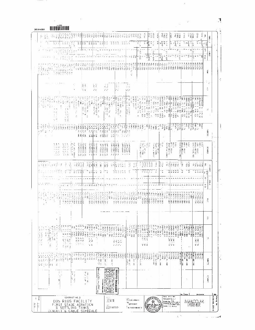
1. Question: If we are to replace the cables and conduit, please provide the existing connection drawings: 1-line,
controls, PLC Interconnect etc. Response: Please see the attached record drawings as follows: Dos Rios Facility First Stage Aeration & Settling Tanks Conduit & Cable Schedule, Dos Rios Facility First Stage Aeration & Settling Tanks Compressor Building Power Grade Level, and Dos Rios Facility First Stage Aeration & Settling Tanks MCC CB1, CB2&CB6 One Line. Refer to “Changes to Specifications”, items 8.A, 8.B, 8.C.
2. Question: Please provide Specification Sections 16950 referenced in the bid specifications. Response: Please see attached Specification Section 16950. Refer to “Changes to Specifications” Items 1 and 6.
3. Question: Do you have an anticipated start and end date in mind? Response: Anticipated start date is May 17, 2021 and project anticipated duration is 283 days. Please refer to the Supplemental Conditions page SS-2 and the Bid Proposal page BP-1.
4. Question: DO you know the square footage for this project? Response: The existing blower building has an approximate square footage of 10664 square feet.
5. Question: Would it be possible to get a two week extension on the bid due date? The old Siemens Allis motor
frame size is no longer available, so the new replacement motor will not be an exact dimensional drop replacement. We received the new motor outline drawings this morning and are reviewing for differences. Additional time is required to determine what site modifications will be needed. Our goal is provide SAWS a reliable solution.
Response: We do not plan to adjust the bid due date at this time.

SAN ANTONIO WATER SYSTEM 2 of 3 Steven M. Clouse WRC Blower Motors No.1 and 5 Replacement Project - IFB | ADDENDUM 3
6. Question: Specification Sections 16406.1 2.20 D and 16406.2 2.20 D both calls for contractor shall retain Howden-Roots as tesing laborty service to record the vibration of exisign blower and motor prior to removal of the motor. Does SAWS or engineering have a contact information for Howden-Roots?
Response: Please use the following contact information for Howden Roots: Douglas Blint at Howden Roots, LLC 900 W Mount
Street, Connersville, IN 47331 USA Phone 765 827 9244. 7. Question: In regards to the Blower # 1, currently the 3000HP motor & compressor is not coupled together. Per the
above specification section. This would require re-aligning & coupling the motor & compressor to perform the required testing prior to the motor replacement. Please clarify if this is the desired work to be performed in the existing state.
Response: No the contractor is not required to re-align & couple the existing motor & compressor to perform the required
testing prior to the motor replacement. Blower #1 motor has serious vibration issues when coupled together to its blower. Refer to “Changes to the Specifications”, item 2.
8. Question: How long have the motors been out of service? Response: Blower No. 1 last ran from July 2, 2018 to August 2, 2018 and Blower No. 5 last ran from May 1, 2019 to
May 6, 2019. 9. Question: Are the blowers in good working conditions? Response: Yes the blowers are in good working conditions based on past input to SAWS from Howden Roots, LLC. 10. Question: Are maintenance activities being performed on a regular basis? Response: Yes maintenance activities are being performed on a regular basis. 11. Question: Why were the motors taken out of service? Response: Blower motors 1 & 5 have developed serious vibration issues when coupled with their respective blowers. 12. Question: If related to vibration, do you have any vibration data that can be shared? Response: Vibration data as available will be provided to the contractor after the project notice to proceed.
CHANGES TO THE SPECIFICATIONS
1. Technical specifications Table of Contents A. Add Specification 16950 Electrical Testing after Section 16410 Power Factor Correction Capacitors.
2. Specification 16010 paragraph 1.03 B.
A. Add the following for new note 7: “If the new motor termination box location is shifted from the location of the existing motor termination box, the Contractor shall be responsible for modifications to existing termination box base to accommodate new termination box. In addition, Contractor shall be responsible for replacement of 5 kV power cables fed from existing MCC to motor termination box if there is insufficient cable length to new location of motor termination box.”
3. Specification 16120
A. Replace entire Specification 16120 with Specification 16120 as attached.
4. Specification 16406.1 paragraph 2.20 D 1.


SAN ANTONIO WATER SYSTEM
STEVEN M. CLOUSE WRC BLOWER 16950 - 1 ELECTRICAL TESING STEVEN M. CLOUSE WRC BLOWER
MOTORS NO. 1 AND 5 REPLACEMENT ADDENDUM 3
SECTION 16950
ELECTRICAL TESTING
PART 1 GENERAL
1.01 SCOPE
A. CONTRACTOR will provide, and pay the cost of, electrical testing by an independent testing
firm. This cost shall be included in the Contract Bid.
B. The CONTRACTOR shall immediately correct all deficiencies discovered during testing by the
independent firm.
1.02 REFERENCES
A. International Electrical Testing Association – Acceptance Testing Specifications (NETA-ATS),
current version.
B. Related equipment specifications in all sections of Division 16.
1.03 SUBMITTALS
A. Administrative Submittals: Submit 30 days prior to performing inspections or tests:
1. Schedule for performing inspection and tests.
2. List references to be used for each test.
3. Sample copy of equipment and materials inspection form(s).
4. Sample copy of individual device test form.
5. Sample copy of individual system test form.
B. Quality Control Submittals: Submit within 15 days after completion of test:
1. Test or inspection reports and certificates for each electrical item tested.
C. Contract Closeout Submittals:
1. Operation and Maintenance Data:
a. In accordance with Section 01830, Operation and Maintenance Data.
b. After test or inspection reports and certificates have been reviewed by OWNER and
returned, insert a copy of each in operation and maintenance manual.
1.04 QUALITY ASSURANCE
A. Testing Firm Qualifications:
1. Corporately and financially independent organization functioning as an unbiased authority,
for a minimum of 5 years.
2. Professionally independent of manufacturers, suppliers, and installers of electrical
equipment and systems being tested.
3. Employer of engineers and technicians regularly engaged in testing and inspecting
electrical equipment, installations, and systems.
4. Supervising technician having a minimum of 5 years testing experience on similar
projects.
SAN ANTONIO WATER SYSTEM
STEVEN M. CLOUSE WRC BLOWER 16950 - 2 ELECTRICAL TESING STEVEN M. CLOUSE WRC BLOWER
MOTORS NO. 1 AND 5 REPLACEMENT ADDENDUM 3
5. Full-time employed Registered Professional Engineer to provide comprehensive project
report outlining services performed, results of such services, recommendations, actions
taken, and opinions.
B. Test equipment shall have an operating accuracy equal to, or greater than, requirements
established at NETA-ATS.
C. Test instrument calibration shall be in accordance with NETA-ATS.
1.05 SEQUENCE AND SCHEDULING
A. Perform inspection and electrical tests after equipment has been installed.
B. Perform tests with apparatus de-energized whenever feasible.
C. Inspection and electrical tests on energized equipment are to be:
1. Scheduled with OWNER prior to de-energization.
2. Minimized to avoid extended period of interruption to the operating plant equipment.
D. Notify OWNER at least 24 hours prior to performing tests on energized electrical equipment.
PART 2 PRODUCTS – NOT USED
PART 3 EXECUTION
3.01 GENERAL
A. Tests specified in this section are to be performed in accordance with the requirements of
Section 01650, FACILITY STARTUP/COMMISSIONING.
B. Tests and inspection shall establish that:
1. Electrical equipment is operational within industry and manufacturer’s tolerances.
2. Installation operates properly.
3. Equipment is suitable for energization.
4. Installation conforms to requirements of Contract Documents and NFPA 70, NFPA 70E,
and ANSI C2.
C. Perform inspection and testing in accordance with NETA-ATS, industry standards, and
manufacturer’s recommendations.
D. Set, test, and calibrate protective relays, circuit breakers, and other applicable devices in
accordance with standard values established by a short circuit and coordination study provided
by OWNER.
E. Adjust mechanisms and moving parts for free mechanical movement.
F. Adjust adjustable relays and sensors to correspond to operating conditions, or as recommended
by manufacturer.
G. Verify nameplate data for conformance to Contract Documents.
H. Tighten accessible bolted connections, including wiring connections, with calibrated torque
wrench to manufacturer’s recommendations, or as otherwise specified.

SAN ANTONIO WATER SYSTEM
STEVEN M. CLOUSE WRC BLOWER 16950 - 3 ELECTRICAL TESING STEVEN M. CLOUSE WRC BLOWER
MOTORS NO. 1 AND 5 REPLACEMENT ADDENDUM 3
I. Clean contaminated surfaces with cleaning solvents as recommended by manufacturer.
J. Provide proper lubrication of applicable moving parts.
K. Inform OWNER of working clearances not in accordance with NFPA 70.
3.02 DRY TYPE TRANSFORMERS – LOW VOLTAGE
A. Visual and Mechanical Inspection:
1. Compare equipment nameplate data with drawings and specifications.
2. Physical and insulator damage.
3. Proper winding connections.
4. Bolt torque level in accordance with NETA-ATS, Table 100.12, unless otherwise specified
by manufacturer.
5. Defective wiring.
6. Proper operation of fans, indicators, and auxiliary devices.
7. Removal of shipping brackets, fixtures, or bracing.
8. Free and properly installed resilient mounts.
9. Cleanliness and improper blockage of ventilation passages.
10. Verify that tap-changer is set at correct ratio for rated output voltage under normal
operation conditions.
11. Verify proper secondary voltage phase-to-phase and phase-to-ground after energization
and prior to loading.
B. Electrical Tests:
1. Insulation Resistance Tests:
a. Applied megohmmeter dc voltage for 1 minute in accordance with NETA-ATS,
Table 100.5 for each:
(i) Winding-to-winding.
(ii) Winding-to-ground.
b. Results temperature corrected in accordance with NETA-ATS, Table 100.14.
c. Temperature corrected insulation resistance values equal to, or greater than, ohmic
values established by manufacturer.
d. Insulation resistance test results to compare within 1 percent of adjacent windings.
2. Perform turns ratio tests at all tap positions. Turns ratio test results shall not deviate by
more than one-half percent from either the adjacent coils or the calculated ratio.
3. Verify correct secondary voltage, phase-to-phase and phase-to-neutral, after energization
and prior to loading.
3.03 LOW VOLTAGE CABLES, 600 VOLTS MAXIMUM
A. Visual and Mechanical Inspection:
1. Inspect Each Individual Exposed Power Cable No. 4 and Larger for:
a. Physical damage.
b. Proper connections in accordance with single-line diagram.
c. Cable bends not in conformance with manufacturer’s minimum allowable bending
radius where applicable.
d. Color-coding conformance with specifications.
e. Proper circuit identification.
2. Mechanical Connections For:
a. Proper lug type for conductor material.

SAN ANTONIO WATER SYSTEM
STEVEN M. CLOUSE WRC BLOWER 16950 - 4 ELECTRICAL TESING STEVEN M. CLOUSE WRC BLOWER
MOTORS NO. 1 AND 5 REPLACEMENT ADDENDUM 3
b. Proper lug installation.
c. Bolt torque level in accordance with NETA-ATS, Table 100.12, unless otherwise
specified by manufacturer.
3. Shielded Instrumentation Cables For:
a. Proper shield grounding.
b. Proper terminations.
c. Proper circuit identification.
4. Control Cables For:
a. Proper termination.
b. Proper circuit identification.
5. Cables Terminated Through Window Type CTs: Verify that neutrals and grounds are
terminated for correct operation of protective devices.
B. Electrical Tests for Conductors No. 4 and Larger:
1. Insulation Resistance Tests:
a. Utilize 1,000-volt dc megohmmeter for 600-volt insulated conductors.
b. Test each conductor with respect to ground and to adjacent conductors per IEEE 118
procedures for 1 minute.
c. Evaluate ohmic values by comparison with conductors of same length and type.
d. Investigate values less than 50 megohms.
2. Continuity test by ohmmeter method to ensure proper cable connections.
3.04 MEDIUM VOLTAGE CABLES, 15KV MAXIMUM
A. Visual and Mechanical Inspection:
1. Inspect Each Individual Exposed Cable For:
a. Physical damage plus jacket and insulation condition.
b. Proper connections in accordance with single-line diagram.
c. Proper cable support.
d. Proper cable termination.
e. Cable bends not in conformance with manufacturer’s minimum allowable bending
radius.
f. Proper arc and fireproofing in common cable areas.
g. Proper circuit and phase identification.
2. Mechanical Connections For:
a. Proper lug type for conductor material.
b. Proper lug installation.
c. Bolt torque level in accordance with NETA-ATS, Table 100.12, unless otherwise
specified by manufacturers.
3. Conductors Terminated Through Window Type CTs: Verify that neutrals and grounds are
terminated for correct operation of protective devices.
B. Electrical Tests:
1. Insulation Resistance Tests:
a. Utilize a megohmmeter with a voltage output of at least 2500 volts.
b. Test each cable individually with remaining cables and shields grounded.
c. Test each conductor with respect to ground and to adjacent conductors in accordance
with IEEE 118 procedures for 1 minute.
d. Evaluate ohmic values by comparison with conductors of same length and type.
e. Investigate values less than 50 megohms.
2. High Potential dc Tests:

SAN ANTONIO WATER SYSTEM
STEVEN M. CLOUSE WRC BLOWER 16950 - 5 ELECTRICAL TESING STEVEN M. CLOUSE WRC BLOWER
MOTORS NO. 1 AND 5 REPLACEMENT ADDENDUM 3
a. In accordance with NEMA WC 7 for TR-XLP and NEMA WC 8 for EPR insulated
conductors.
b. Each conductor section tested with:
(i) Splices and terminations in-place but disconnected from equipment.
(ii) Remaining conductors and shields grounded in accordance with IEEE 400.
c. Apply maximum dc test voltage in accordance with NETA-ATS, Table 100.6.
d. Measure only the leakage current associated with conductor.
e. Utilize guard ring or field reduction sphere to suppress corona at disconnected
terminations.
f. Maximum test voltage shall not exceed limits for terminators specified in IEEE 48 or
manufacturer’s specifications.
g. Apply test voltage in minimum of five equal increments until maximum acceptable
test voltage is reached.
(i) Increments not to exceed ac voltage rating of conductor.
(ii) Record dc leakage current at each step after a constant stabilization time
consistent with system charging current.
h. Raise conductor to specified maximum test voltage and hold for 15 minutes on
shielded cable and 5 minutes on non-shielded cable; or as specified by conductor
manufacturer. Record dc leakage current at 30 seconds and 1 minute and at 1-minute
intervals, thereafter.
i. Immediately following test, ground conductor for adequate time period to drain
insulation stored charge.
j. Test results evaluated on a pass/fail basis.
3.05 MEDIUM VOLTAGE METAL ENCLOSED AIR SWITCHES:
A. Visual and Mechanical Inspection:
1. Proper blade pressure, alignment, and arch interrupter operation.
2. Compare equipment nameplate data with drawings and specifications.
3. Proper operation of operating mechanism.
4. Proper contact condition.
5. Adequate mechanical support for each fuse.
6. Proper contact-to-contact tightness between fuse clip and fuse.
7. Bus and cable connection tightness.
8. Proper phase barrier material and installation.
9. Proper operation of indicating devices.
10. Installation of expulsion limiting devices on expulsion type element holders.
11. Verify that fuse links and types correspond to one-line diagram.
12. Perform mechanical operational test to verify electrical and mechanical interlocking
system operation and sequencing.
13. Perform phasing check on double-ended air switch arrangements to ensure proper bus
phasing from each source.
14. Verify tightness of accessible bolted electrical connections by calibrated torque-wrench
method in accordance with manufacturer’s published data or NETA-ATS Table 100.12.
B. Electrical Tests:
1. Insulation Resistance Tests:
a. Applied megohmmeter dc voltage in accordance with NETA-ATS, Table 100.1.

SAN ANTONIO WATER SYSTEM
STEVEN M. CLOUSE WRC BLOWER 16950 - 6 ELECTRICAL TESING STEVEN M. CLOUSE WRC BLOWER
MOTORS NO. 1 AND 5 REPLACEMENT ADDENDUM 3
b. Phase-to-phase and phase-to-ground for 1 minute on each pole.
c. Insulation resistance values equal to, or greater than, ohmic values established by
manufacturer.
2. Contact Resistance Tests:
a. Contact resistance in microhms across each switch blade and fuse holder.
b. Investigate values exceeding 500 microhms or deviation of 50 percent or more from
adjacent poles or similar switches.
3. Overpotential Tests:
a. Applied dc voltage in accordance with NETA-ATS, Table 100.11.
b. Phase-to-phase and phase-to-ground for 1 minute.
c. Test results evaluated on pass/fail basis.
3.06 MOLDED AND INSULATED CASE CIRCUIT BREAKERS
A. General: Inspection and testing limited to circuit breakers rated 100 amperes and larger and to
motor circuit protector breakers rated 50 amperes and larger.
B. Visual and Mechanical Inspection:
1. Proper mounting.
2. Proper conductor size.
3. Feeder designation according to nameplate and one-line diagram.
4. Cracked casings.
5. Connection bolt torque level in accordance with NETA-ATS, Table 100.12.
6. Operate breaker to verify smooth operation.
7. Compare frame size and trip setting with circuit breaker schedules or one-line diagram.
8. Verify that terminals are suitable for 75°C rated insulated conductors.
C. Electrical Tests:
1. Insulation Resistance Tests:
a. Applied megohmmeter dc voltage in accordance with NETA-ATS, Table 100.1.
b. For 1 minute on each pole, phase-to-phase and phase-to-ground with the circuit
breaker closed, and across each open pole.
c. Insulation resistance values equal to, or greater than, ohmic values established by
manufacturer.
2. Contact Resistance Tests:
a. Between the line and load stab of closed contact resistance in microhms across each
pole.
b. Investigate deviation of 25 percent or more from adjacent poles and similar breakers.
3. Determine long-time pickup and delay by primary current injection.
4. Determine short-time pickup and delay by primary current injection.
5. Determine ground-fault pickup and time delay by primary current injection.
6. Perform minimum pickup voltage tests on shunt trip and close coils in accordance with
manufacturer’s published data.
7. Verify correct operation of auxiliary feature such as trip and pickup indicators, zone
interlocking, electrical close and trip operation, trip-free, anti-pump function, and trip unit
battery condition. Reset all trip logs and indicators.
8. Verify operation or charging mechanism.

SAN ANTONIO WATER SYSTEM
STEVEN M. CLOUSE WRC BLOWER 16950 - 7 ELECTRICAL TESING STEVEN M. CLOUSE WRC BLOWER
MOTORS NO. 1 AND 5 REPLACEMENT ADDENDUM 3
9. Control Wiring Tests:
a. Insulation resistance test at 1,000 volts dc on control wiring except that connected to
solid-state components.
b. Insulation resistance to be 1 megohm minimum.
3.07 PROTECTIVE RELAYS
A. Visual and Mechanical Inspection:
1. Compare equipment nameplate data with drawings and specifications.
2. Inspect relays and cases for physical damage. Remove shipping restraint material.
3. Verify the unit is clean.
4. Relay Case:
a. Tighten case connections.
b. Inspect cover for correct gasket seal.
c. Clean cover glass. Inspect shorting hardware, connection paddles, and knife
switches.
d. Remove any foreign material from the case.
e. Verify target reset.
5. Set relays in accordance with coordination study.
B. Electrical Tests:
1. Inspect indicators.
a. Verify operation of all light-emitting diode indicators.
b. Set contrast for liquid-crystal display readouts.
2. Control verification:
a. Functional tests - Verify that each relay contact performs its intended function in the
control scheme including breaker trip tests, close inhibit tests, 86 lockout tests, and
alarm functions.
b. In-service monitoring – After the equipment is initially energized, measure magnitude
and phase angle of all inputs and compare to expected values.
3.08 INSTRUMENT TRANSFORMERS
A. Visual and Mechanical Inspection:
1. Visually Check Current, Potential, and Control Transformers For:
a. Cracked insulation.
b. Broken leads or defective wiring.
c. Proper connections.
d. Adequate clearances between primary and secondary circuit wiring.
2. Verify Mechanically That:
a. Grounding and shorting connections have good contact.
b. Withdrawal mechanism and grounding operation, when applicable, operate properly.
3. Verify proper primary and secondary fuse sizes for potential transformers.
4. Bolt torque level in accordance with NETA-ATS, Table 100.12.
B. Electrical Tests:
1. Current Transformer Tests:
a. Insulation resistance test of transformer and wiring-to-ground at 1,000 volts dc for 1
minute.
b. Polarity test. Polarity results shall agree with transformer markings.

SAN ANTONIO WATER SYSTEM
STEVEN M. CLOUSE WRC BLOWER 16950 - 8 ELECTRICAL TESING STEVEN M. CLOUSE WRC BLOWER
MOTORS NO. 1 AND 5 REPLACEMENT ADDENDUM 3
c. Ratio-verification test using the voltage or current method in accordance with
ANSI/IEEE C57.13.1.
d. Excitation test on transformers used for relaying applications in accordance with
ANSI/IEEE C57.13.1.
e. Measure current circuit burdens at transformer terminals in accordance with
ANSI/IEEE C57.13.1. Measured burdens shall be compared to instrument
transformer ratings.
f. When applicable, perform insulation-resistance tests on the primary winding with the
secondary grounded. Test voltages shall be in accordance with Table 100.5.
g. When applicable, perform dielectric withstand tests on the primary winding with the
secondary grounded.
(i) Test voltages shall be in accordance with Table 100.9.
(ii) If no evidence of distress or insulation failure is observed by the end of the total
time of voltage application during the dielectric withstand test, the primary
winding is considered to have passed the test.
h. Perform power-factor or dissipation-factor tests in accordance with test equipment
manufacturer’s published data.
i. Verify that current transformer secondary circuits are grounded and have only one
grounding point in accordance with ANSI/IEEE C57.13.3. That grounding point
should be located as specified by the ENGINEER in the project drawings.
2. Potential Transformer Tests:
a. Insulation resistance test at test voltages in accordance with NETA - ATS, Table
100.5 for 1 minute on:
(i) Winding-to-winding.
(ii) Winding-to-ground.
b. Insulation resistance measurement shall not be less than that calculated by formula in
NETA-ATS, Table 100.5.
c. Polarity test to verify polarity marks or H1-X1 relationship as applicable. Polarity
results shall agree with transformer markings.
d. Turns-ratio test on all tap positions. Ratio errors shall be in accordance with C57.13.
e. Measure voltage circuit burdens at transformer terminals. Measured burdens shall be
compared to instrument transformer ratings.
f. When applicable, perform dielectric withstand tests on the primary winding with the
secondary grounded. The test voltage shall be applied for one minute.
(i) Test voltages shall be in accordance with Table 100.9.
(ii) If no evidence of distress or insulation failure is observed by the end of the total
time of voltage application during the dielectric withstand test, the primary
winding is considered to have passed the test.
g. Power-factor or dissipation-factor tests in accordance with test equipment
manufacturer’s published data.
h. Verify that voltage transformer secondary circuits are grounded and have only one
grounding point in accordance with ANSI/IEEE C57.13.3. The grounding point
should be located as specified by the ENGINEER in the project drawings.
3.09 METERING AND INSTRUMENTATION:
A. Visual and Mechanical/Electrical Inspection:
1. Verify meter and instrument connections in accordance with appropriate diagrams.
2. Verify meter multipliers.
3. Verify that meter and instrument types and scales conform to Contract Documents.
4. Check calibration of meters at cardinal points.

SAN ANTONIO WATER SYSTEM
STEVEN M. CLOUSE WRC BLOWER 16950 - 9 ELECTRICAL TESING STEVEN M. CLOUSE WRC BLOWER
MOTORS NO. 1 AND 5 REPLACEMENT ADDENDUM 3
5. Check calibration of transducers and transmitters.
6. Check set-point and operation of pressure switches.
7. Verify operation of heat trace systems.
8. Check tightness of electrical connections.
9. Verify unit is grounded in accordance with manufacturer’s instructions.
10. Set all required parameters including instrument transformer ratios, system type,
frequency, power demand methods/intervals, and communications requirements.
11. Apply voltage or current as appropriate to each analog input and verify correct
measurement and indication.
3.10 SUPERVISORY CONTROL AND DATA ACQUISITION (SCADA)
A. Visual and Mechanical Inspection:
1. Verify System Wiring:
a. Compare wiring to elementary diagrams.
b. Check for proper conductor lacing and bundling.
c. Check for proper conductor identification.
d. Check lugs and terminations.
2. Verify labels and nameplates.
3. Verify component equipment and instrumentation conforms to Contract Documents.
4. Verify component electrical and mechanical connections conform to manufacturer’s
instructions.
B. Operational Testing:
1. Check each control panel display and switch for proper control loop function.
2. Verify each Input/Output point from the end element to the remote central operations
center.
3. Verify calibration and scale of each analog quantity.
4. Verify performance of uninterruptible power supply. Verify on-battery voltage and
waveform.
3.11 GROUNDING SYSTEMS
A. Visual and Mechanical Inspection:
1. Ground system in compliance with drawings, specifications, and NFPA 70 National
Electrical Code Article 250.
2. Grounding system electrical and mechanical connections free of corrosion.
3. Equipment and circuit grounds in motor control centers and switchgear assemblies for
proper connection and tightness.
4. Ground bus connections in motor control centers and switchgear assemblies for proper
termination and tightness.
5. Effective transformer core and equipment grounding.
6. Accessible connections to grounding electrodes for proper fit and tightness.
7. Accessible exothermic-weld grounding connections to verify that molds were fully filled
and proper bonding was obtained.
B. Electrical Tests:
1. Fall-Of-Potential Test:
a. In accordance with ANSI/IEEE 81, Section 8.2.1.5 for measurement of main ground
system’s resistance.

SAN ANTONIO WATER SYSTEM
STEVEN M. CLOUSE WRC BLOWER 16950 - 10 ELECTRICAL TESING STEVEN M. CLOUSE WRC BLOWER
MOTORS NO. 1 AND 5 REPLACEMENT ADDENDUM 3
b. Main ground electrode system resistance to ground to be no greater than 5 ohms for
large commercial or industrial systems and 1.0 ohm or less for generating or
transmission station grounds unless otherwise specified by the OWNER.
c. Investigate point-to-point resistance values that exceed 0.5 ohm.
3.12 AC INDUCTION MOTORS
A. General: Inspection and testing limited to motors rated 5 hp and larger.
B. Visual and Mechanical Inspection:
1. Proper electrical and grounding connections.
2. Shaft alignment.
3. Blockage of ventilating air passageways.
4. Operation of cooling fans.
5. Operate Motor and Check For:
a. Excessive mechanical and electrical noise.
b. Overheating.
c. Correct rotation.
d. Check resistance temperature detectors, or motor inherent protectors for function
ability and proper operation.
e. Excessive vibration.
6. Check operation of space heaters.
7. Cable connection bolt torque level in accordance with NETA-ATS, Table 100.12.
C. Electrical Tests:
1. Insulation Resistance Tests:
a. In accordance with ANSI/IEEE 43 at test voltages established by NETA-ATS, Table
100.1 for:
(i) Motors above 200 hp for 10-minute duration with resistance’s tabulated at 30
seconds, 1 minute, and 10 minutes.
(ii) Motors 200 hp and less for 1-minute duration with resistance’s tabulated at 30
and 60 seconds.
b. Insulation resistance values equal to, or greater than, ohmic values established by
manufacturers.
2. Calculate polarization index ratios for motors 200 hp and above. Investigate index ratios
less than 2.0 for Class B or Class F insulation.
3. Insulation resistance test on insulated bearings in accordance with manufacturer’s
instructions.
4. Measure running current and voltage, and evaluate relative to load conditions and
nameplate full-load amperes.
5. Perform insulation power-factor or dissipation-factor tests. Values shall be compared to
manufacturer’s published data.
6. Perform resistance tests on resistance temperature detector (RTD) circuits.
a. fuses.
3.13 MEDIUM VOLTAGE MOTOR CONTROL CENTERS
A. Visual and Mechanical Inspection:
1. Insulator damage and contaminated surfaces.
2. Proper barrier and shutter installation and operation.
3. Proper operation of indicating devices.

SAN ANTONIO WATER SYSTEM
STEVEN M. CLOUSE WRC BLOWER 16950 - 11 ELECTRICAL TESING STEVEN M. CLOUSE WRC BLOWER
MOTORS NO. 1 AND 5 REPLACEMENT ADDENDUM 3
4. Proper overload protection.
5. Blockage of air-cooling passages.
6. Proper operation of drawout elements.
7. Integrity and contamination of bus insulation system.
8. Check Nameplates for Proper Identification of Each.
a. Equipment title and tag number with latest one-line diagram.
b. Pushbutton.
c. Control switch.
d. Pilot light.
e. Control relay.
f. Circuit breaker.
g. Indicating meter.
9. Verify that fuse sizes and types conform to Contract Documents.
10. Check Bus Connections for High Resistance by Low Resistance Ohmmeter and Calibrated
Torque Wrench Applied to Bolted Joints:
a. Ohmic value to be zero.
b. Bolt torque level in accordance with NETA-ATS, Table 100.12, unless otherwise
specified by manufacturer.
11. Check Operation and Sequencing of Electrical and Mechanical Interlock Systems By:
a. Closure attempt for locked open devices.
b. Opening attempt for locked closed devices.
c. Key exchange to operate devices in OFF-NORMAL positions.
12. Verify performance of each control device and feature furnished as part of the motor
control center.
13. Control Wiring:
a. Compare wiring to local and remote control, and protective devices with elementary
diagrams.
b. Check for proper conductor lacing and bundling.
c. Check for proper conductor identification.
d. Check for proper conductor lugs and connections.
14. Exercise active components.
15. Inspect Magnetic Contactors For:
a. Correct mechanical operations.
b. Correct contact gap, wipe, alignment, and pressure.
c. Correct torque of connections.
16. Perform phasing check on double-ended motor control centers to ensure proper bus
phasing from each source.
B. Electrical Tests:
1. Insulation Resistance Tests:
a. Applied megohmmeter dc voltage in accordance with NETA-ATS, Table 100.1.
b. Bus section phase-to-phase and phase-to-ground for 1 minute on each phase.
c. Contactor phase-to-ground and across open contacts for 1 minute on each phase.
d. Starter section phase-to-phase and phase-to-ground on each phase with starter
contacts closed and protective devices open.
e. Test values to comply with NETA-ATS, Table 100.1.
2. Bottle integrity test for vacuum contactors in accordance with manufacturer’s procedure.
3. Test by Primary Current Injection:
a. Overload units at sensors using 300 percent of motor full-load current.
(i) Overload trip times to be in accordance with manufacturer’s published data.

SAN ANTONIO WATER SYSTEM
STEVEN M. CLOUSE WRC BLOWER 16950 - 12 ELECTRICAL TESING STEVEN M. CLOUSE WRC BLOWER
MOTORS NO. 1 AND 5 REPLACEMENT ADDENDUM 3
b. Check voltage levels at each point on terminal boards and each device terminal.
4. Control Wiring Tests:
a. Apply secondary voltage on control power and potential circuits.
b. Check voltage levels at each point on terminal boards and at each device terminal.
c. Insulation resistance test at 1,000 volts dc on control wiring except that connected to
solid-state components.
(i) Insulation resistance to be 1 megohm minimum.
5. Test indicating and monitoring devices for proper operation.
6. Perform setup and testing of solid-state relays and multifunction microprocessor based
protective devices in accordance with manufacturer’s instructions.
7. Measure Contact and Power Fuse Resistance:
a. Contact resistance shall not exceed manufacturer’s recommended values.
b. Resistance of power fuses not to deviate more than 15 percent between identical
fuses.
3.14 THERMOGRAPHIC SURVEY
A. General:
1. Equipment to be inspected shall include all current-carrying devices including but not
limited to switchboards, panelboards, breakers, fuse holders, switches and bus
connections/joints.
B. Visual and Mechanical Inspection:
1. Perform thermographic survey when load is applied to the system.
2. Remove all necessary covers prior to thermographic inspection. Use appropriate caution,
safety devices, and personal protective equipment.
3. Perform a follow-up thermographic survey within 12 months of final acceptance by the
OWNER.
C. Report:
1. Provide a report which includes the following:
a. Description of equipment tested.
b. Discrepancies.
c. Temperature difference between the area of concern and the reference area.
d. Probable cause of temperature difference.
e. Areas inspected. Identify inaccessible and/or unobservable areas and/or equipment.
f. Identify load conditions at time of inspection.
g. Provide photographs and/or thermograms of the deficient area.
h. Recommended action.
D. Test Parameters:
1. Inspect distribution systems with imaging equipment capable of detecting a minimum
temperature difference of 1° C at 30° C.
2. Equipment shall detect emitted radiation and convert detected radiation to visual signal.
3. Thermographic surveys should be performed during periods of maximum possible
loading. Refer to ANSI/NFPA 70B, Section 21.17.
END OF SECTION

SAN ANTONIO WATER SYSTEM 16120 - 1 CONDUCTORS
STEVEN M. CLOUSE WRC BLOWER
MOTORS NO. 1 AND 5 REPLACEMENT
ADDENDUM 3
SECTION 16120
CONDUCTORS
PART 1 GENERAL
1.01 SUBMITTALS:
A. Shop Drawings:
1. Wire and cable descriptive product information.
2. Wire and cable accessories descriptive product information.
B. Quality Control Submittals:
1. Factory Test Report for conductors 600 volts and below.
2. Factory Test Report per AEIC, including AEIC qualification report for conductors above
600 volts.
3. Manufacturer’s data sheets and catalog data.
1.02 UL COMPLIANCE:
A. Materials manufactured within scope of Underwriters Laboratories shall conform to UL
Standards and have an applied UL listing mark.
PART 2 PRODUCTS
2.01 CONDUCTORS 600 VOLTS AND BELOW:
A. Conform to applicable requirements of:
1. UL 83
2. ASTM Standards
3. Federal Specification A-A-59544
4. NFPA 70, Article 725
B. Conductor Type: Stranded Copper:
C. Insulation: Type THHN/THWN 90oC. Allowable conductor ampacity shall be as listed for 75
o
C Temperature rating even for conductor with 90o C rated insulation.
D. No conductor smaller than #12 AWG shall be used.
E. Permanently and legibly marked with manufacturer's name, maximum working voltage for
which cable was tested, type of cable, and UL listing mark.
F. All cable shall be suitable for installation in open air and in conduit (both above and below
ground).
2.02 600-VOLT RATED INSTRUMENTATION CABLE:
A. General:

SAN ANTONIO WATER SYSTEM 16120 - 2 CONDUCTORS
STEVEN M. CLOUSE WRC BLOWER
MOTORS NO. 1 AND 5 REPLACEMENT
ADDENDUM 3
1. NFPA 70, Article 340, or UL 13 Listed Power Limited Circuit Cable
2. Tray Rated Cable (Type TC) shall meet the requirements of UL 1277 and UL 1581. Shall
also meet the Flame Test requirements of IEEE 383 or UL 1685. Tray rated cable shall be
installed in all cable trays.
3. Permanently and legibly marked with manufacturer's name, maximum working voltage for
which cable was tested, type of cable, and UL listing mark.
4. Suitable for installation in open air, in cable trays, or conduit (both above and below
ground).
5. Minimum Temperature Rating: 90° C dry locations, 75° C wet locations.
6. Overall Outer Jacket: PVC, flame-retardant, sunlight-and oil-resistant.
B. Twisted, Shielded Pair Instrumentation Cable (TW/SH/PR):
1. Single pair.
2. Designed for noise rejection for process control, computer, or data log applications.
3. Outer Jacket: PVC.
4. Individual Pair Shield: double-faced aluminum/synthetic polymer overlapped to provide
100 percent coverage.
5. Conductors:
a. No. 16 AWG bare soft annealed copper, Class B, seven-strand concentric, meeting
requirements of ASTM B8.
b. 20 AWG, seven-strand tinned copper drain wire.
c. Insulation: 15-mil nominal PVC.
d. Jacket: 4-mil nominal PVC.
e. Color Code: Pair conductors black (positive) and white (negative).
6. Standards:
a. UL 1685
b. When installed in cable trays shall be cable tray rated (Type TC).
c. NEMA WC 55
7. Manufacturers:
a. Okonite
b. AlphaWire
c. Belden
C. Twisted, Shielded Pair Instrumentation Cable for RS485 Applications (RS485 TW/SH):
1. Single pair.
2. Designed for noise rejection for Modbus RS485 applications.
3. Outer Jacket: PVC.
4. Individual Pair Shield: double-faced aluminum/synthetic polymer overlapped to provide
100 percent coverage. Tinned copper braid shield with 90% coverage.
5. Conductors:

SAN ANTONIO WATER SYSTEM 16120 - 3 CONDUCTORS
STEVEN M. CLOUSE WRC BLOWER
MOTORS NO. 1 AND 5 REPLACEMENT
ADDENDUM 3
a. No. 24 AWG bare soft annealed copper, Class B, seven-strand concentric, meeting
requirements of ASTM B8.
b. 24 AWG, seven-strand tinned copper drain wire.
c. Insulation: 23-mil nominal polyethylene.
d. Jacket: 35-mil nominal PVC.
e. Color Code: Pair conductors blue and white.
6. Standards:
a. UL 1685
b. When installed in cable trays shall be cable tray rated (Type TC).
c. NEMA WC 55
7. Manufacturers:
a. Belden type 9841 or equal from below manufacturers:
(i) AlphaWire
(ii) Okonite
D. Twisted, Shielded Triad Instrumentation Cable (TW/SH/TRIAD):
1. Single triad.
2. Designed for noise rejection for process control, computer, or data log applications.
3. Outer Jacket: PVC.
4. Individual Pair Shield: double-faced aluminum/synthetic polymer, overlapped to provide
100 percent coverage.
5. Conductors:
a. No. 16 AWG bare soft annealed copper, Class B, seven-strand concentric, ASTM B8.
b. 20 AWG, seven-strand tinned copper drain wire.
c. Insulation: 15-mil PVC.
d. Color Code: Triad conductors black, red, and white.
6. Standards:
a. UL 1685
b. When installed in cable trays shall be cable tray rated (Type TC).
c. NEMA WC 55
7. Manufacturers:
a. Okonite
b. AlphaWire
c. Belden
2.03 GROUNDING CONDUCTORS:
A. Equipment:

SAN ANTONIO WATER SYSTEM 16120 - 4 CONDUCTORS
STEVEN M. CLOUSE WRC BLOWER
MOTORS NO. 1 AND 5 REPLACEMENT
ADDENDUM 3
1. No. 8 AWG and Larger: Stranded Bare Copper, Class B stranding, soft drawn., Type
THHN/THWN, insulation
a. Color: Green
2. No. 10 AWG and smaller: Solid Bare Copper or Stranded copper with, Type
THHN/THWN, insulation
a. Color: Green
3. Do not install bare grounding conductors in the same conduit as insulated power
conductors.
B. Direct Buried: Stranded bare copper, class B stranding soft drawn.
2.04 ACCESSORIES FOR CONDUCTORS 600 VOLTS AND BELOW:
A. Tape:
1. General Purpose, Flame-Retardant:
a. 7-mil, vinyl plastic, Scotch Brand 33, rated for 105° C, meeting requirements of UL
510.
2. Flame Retardant, Cold and Weather Resistant:
a. 8.5-mil, vinyl plastic, Scotch Brand 88, rated for 105° C meeting requirements of UL
510.
3. Arc and Fireproofing:
a. 30-mil, elastomer, Scotch; Brand 77, with Scotch Brand 69-glass cloth tape binder.
B. Identification Devices:
1. Sleeve: Permanent, PVC, yellow or white, 2-inch minimum, with legible machine-printed
black markings.
2. Marker Plate: Nylon, with legible designations permanently hot stamped on plate.
3. Grounding Conductor: Permanent green heat-shrink sleeve, 2-inch minimum.
4. Manufacturers:
a. Brady
b. Thomas & Betts
c. 3M
d. Panduit
C. Connectors and Terminations:
1. Nylon, Self-Insulated Crimp Connectors:
a. Manufacturers and Products:
(i) Thomas & Betts; Sta-Kon
(ii) Burndy; Insulink

SAN ANTONIO WATER SYSTEM 16120 - 5 CONDUCTORS
STEVEN M. CLOUSE WRC BLOWER
MOTORS NO. 1 AND 5 REPLACEMENT
ADDENDUM 3
(iii) ILSCO
2. Nylon, Self-Insulated, Crimp Locking-Fork, Torque-Type Terminator:
a. Manufacturers and Products:
(i) Thomas & Betts; Sta-Kon
(ii) Burndy; Insulink
(iii) ILSCO
3. Self-Insulated, Free spring Wire Connector (Wire Nuts):
a. Plated steel, square wire springs.
b. UL Standard 486C.
c. Manufacturers and Product:
(i) Thomas & Betts
(ii) Ideal; Twister
D. Cable Lugs:
1. In accordance with NEMA CC 1.
2. Rated 600 volts of same material as conductor metal.
3. Insulated, Locking-Fork, Compression Lugs:
a. Suitable for use with 75°C wire at full NFPA 70, 75°C ampacity.
b. Manufacturers and Products:
(i) Thomas & Betts; Sta-Kon
(ii) ILSCO; ILSCONS
4. Uninsulated Crimp Connectors and Terminators:
a. Suitable for use with 75°C wire at full NFPA 70, 75°C ampacity. Manufacturers and
Products:
(i) Square D; Versitide
(ii) Thomas & Betts; Color-Keyed
(iii) ILSCO
5. Uninsulated, Bolted, Two-Way Connectors and Terminators:
a. Manufacturers and Products:
(i) Thomas & Betts; Locktite
(ii) Burndy; Quiklug
(iii) ILSCO
E. Cable Ties: Nylon, adjustable, self-locking, and reusable.
1. Manufacturer and Product: Thomas & Betts; TY-RAP.
F. Heat Shrinkable Insulation: Thermally stabilized, cross-linked polyolefin.

SAN ANTONIO WATER SYSTEM 16120 - 6 CONDUCTORS
STEVEN M. CLOUSE WRC BLOWER
MOTORS NO. 1 AND 5 REPLACEMENT
ADDENDUM 3
1. Manufacturer and Product: Thomas & Betts; SHRINK-KON.
2.05 MEDIUM-VOLTAGE POWER CABLES:
A. General:
1. Cable shall be suitable for use in conduit, underground duct and cable tray.
2. Cable shall be 5kV rated single-conductor, copper, shielded, jacketed, 100% insulation,
flame retardant cable.
3. Maximum operating temperature rating of the cable shall be either 90° C (MV90) or 105°
C (MV 105). Maximum allowable ampacity will be in accordance with the 90° C rating,
as listed in NEC Article 310. The 105° C ampacity ratings shall not be applied.
B. Cable Standards:
1. UL 1072, Medium-Voltage Power Cables.
2. ICEA S-93-639 (NEMA74), 5-46kV Shielded Power Cable.
3. UL 1685 (AWG 1/0 and larger), UL Flame Exposure Test.
4. IEEE 1202, Flame Test (70,000 Btu/hr Vertical Tray Test)
5. AEIC CS-8, Qualification Testing.
6. NFPA 70, Article 328.
C. Conductor Standards:
1. ASTM B3 and B8
2. ICEA Part 2
D. Conductor:
1. Class B stranded soft or annealed copper, concentric round or compressed round.
2. Conductors shall have waterproof strand block compound to prevent moisture migration
along the conductor strands.
E. Conductor Shield:
1. Conductor shall have a single non-conducting or semi-conducting extruded stress control
layer over the conductor and firmly bonded to the insulation.
F. Insulation:
1. Insulation material shall be Ethylene Propylene Rubber (EPR) meeting the requirements of
the referenced standards.
2. Nominal Insulation Thickness: 115 mil (.115 inch) for conductors up to and including
1000 kcmil.
G. Insulation Shield:
1. The insulation shall be covered with an extruded layer of semi-conducting thermosetting
material, or 5-mil semi-conducting tape, over which shall be applied a helically wrapped
copper tape shield.

SAN ANTONIO WATER SYSTEM 16120 - 7 CONDUCTORS
STEVEN M. CLOUSE WRC BLOWER
MOTORS NO. 1 AND 5 REPLACEMENT
ADDENDUM 3
2. Copper tape shield shall be 5-mil thickness with 15-25% overlap.
H. Jacket:
1. Cable shall have a protective outer jacket of black Polyvinyl Chloride (PVC) or
Chlorosulfonated Polyethylene (CPE) material. Polyethylene is NOT ACCEPTABLE.
2. Minimum jacket thickness shall be 55 mil (.055 inch) for conductor sizes through No. 1
AWG, and 70 mil (.070 inch) for conductor sizes 1/0 through 1000 kcmil.
I. Identification:
1. Cable shall be identified by surface printing on the jacket, in accordance with UL 1072.
2. Labeling shall include UL Type.
J. Manufacturers:
1. Southwire
2. Kerite
3. American Insulated Wire
2.06 ACCESSORIES FOR MEDIUM VOLTAGE CONDUCTORS:
A. Splice Kits: (SLICES NOT ALLOWED)
B. Termination Kits:
1. Capable of terminating an 8 kV, single-conductor, polymeric-insulated, shielded
conductor.
2. Capable of producing a termination with a current rating equal to, or greater than, the cable
ampacity, meeting Class 1 requirements of IEEE 48.
3. Capable of accommodating any form of construction without the need for special adapters
and/or accessories.
4. Manufacturers:
a. Raychem
b. 3M Co.
c. Kerite
C. Bus Connection Insulation:
1. Heat shrinkable tubing, tape, and sheets of flexible cross linked polymeric material
formulated for high dielectric strength.
2. Tape and sheet products to have coating to prevent adhesion to metal surfaces.
3. Manufacturer: Raychem
D. Cable Lugs:
1. In accordance with NEMA CC1.
2. Rated for 5 kV applications.
3. Copper or bronze material.

SAN ANTONIO WATER SYSTEM 16120 - 8 CONDUCTORS
STEVEN M. CLOUSE WRC BLOWER
MOTORS NO. 1 AND 5 REPLACEMENT
ADDENDUM 3
4. Manufacturers and Products, Uninsulated Closed-End Compression Connectors of the size
and type recommended by the cable manufacturers:
a. Burndy
b. Thomas & Betts
c. Amp
2.07 PULLING COMPOUND:
A. Nontoxic, noncorrosive, noncombustible, nonflammable, wax-based lubricant; UL listed.
B. Suitable for raceway material and conductor jacket material.
C. Manufacturers and Products:
1. Ideal Co.; Yellow 77
2. Polywater, Inc.
3. Cable Grip Co.
2.08 SOURCE QUALITY CONTROL:
A. Conductors 600-Volts and below: Test in accordance with UL 44 and 854 Standards.
B. Medium Voltage Conductors: Test in accordance with NEMA WC 74 and AEIC CS 8.
PART 3 EXECUTION
3.01 GENERAL:
A. Conductor installation to be in accordance with NECA 5055.
B. Conductor and cable sizing shown on Contract Drawings is based on copper conductors, unless
noted otherwise.
C. Do not exceed cable manufacturer's recommendations for maximum pulling tensions and
minimum bending radius.
D. Tighten screws and terminal bolts in accordance with UL 486A for copper conductors.
E. Cable Lugs: Provide with correct number of holes, bolt size, and center-to-center spacing as
required by equipment terminals.
F. Bundling: Where single conductors and cables in manholes, handholes, vaults, cable trays, and
other indicated locations are not wrapped together by some other means, bundle conductors
from each conduit throughout their exposed length with cable ties placed at intervals not
exceeding 18 inches on center.
G. Ream; remove burrs, and clear interior of installed conduit before pulling wires or cables.
H. Concrete encased raceway installation prior to installation of conductors: pull through each
raceway a mandrel approximately ¼ inch smaller than raceway inside diameter.

SAN ANTONIO WATER SYSTEM 16120 - 9 CONDUCTORS
STEVEN M. CLOUSE WRC BLOWER
MOTORS NO. 1 AND 5 REPLACEMENT
ADDENDUM 3
3.02 POWER CONDUCTOR COLOR CODING:
A. Conductors 600 Volts and Below:
1. No. 4 AWG and Larger: Apply general purpose, flame retardant tape at each end, and at
accessible locations wrapped at least six full overlapping turns, covering an area 2 inches
wide.
2. No. 6 AWG and Smaller: Provide colored conductors.
3. Colors:
System Conductor Color
All Systems Equipment Grounding Green
240/120 Volts
Single-Phase, Three-Wire
Grounded Neutral
One Hot Leg
Other Hot Leg
White
Black
Red
208Y/120 Volts
Three-Phase, Four-Wire
Grounded Neutral
Phase A
Phase B
Phase C
White
Black
Red
Blue
240/120 Volts
Three-Phase, Four-Wire
Delta, Center Tap
Ground on Single-Phase
Grounded Neutral
Phase A
High (wild) Leg
Phase C
White
Black
Orange
Blue
480Y/277 Volts
Three-Phase, Four-Wire
Grounded Neutral
Phase A
Phase B
Phase C
White or Gray
Purple
Brown
Yellow
NOTE: Phase A, B, C implies direction of positive phase rotation.
4. Tracer: Outer covering of white with an identifiable colored strip other than green in
accordance with NFPA 70.
B. Medium Voltage Conductors: Apply general purpose, flame retardant tape at each end, and at
accessible locations wrapped at least six (6) full overlapping turns, covering an area 1 ½ to 2
inches wide.
1. Colors:
a. Phase A: Red
b. Phase B: White
c. Phase C: Blue
3.03 CIRCUIT IDENTIFICATION:
A. Circuits Appearing in Circuit Schedules: Identify power, instrumentation, and control
conductor circuits, using circuit schedule designations, at each termination and in accessible

SAN ANTONIO WATER SYSTEM 16120 - 10 CONDUCTORS
STEVEN M. CLOUSE WRC BLOWER
MOTORS NO. 1 AND 5 REPLACEMENT
ADDENDUM 3
locations such as manholes, handholes, panels, switchboards, motor control centers, pull boxes,
and terminal boxes.
B. Labels shall be permanently legible, typed or preprinted. Label shall be Brady Type DAT-292
self-laminating vinyl film or as manufactured by Thomas & Betts, 3M or Panduit.
C. Circuits Not Appearing in Circuit Schedules:
1. Assign circuit name based on device or equipment at load end of circuit.
2. Where this would result in same name being assigned to more than one circuit, add
number or letter to each otherwise identical circuit name to make it unique.
D. Method:
1. Conductors No. 3 AWG and Smaller: Identify with sleeves.
2. Cables, and Conductors No. 2 AWG and Larger:
a. Identify with marker plates.
b. Attach marker plates with nylon tie cord.
3. Taped-on markers or tags relying on adhesives not permitted.
3.04 CONDUCTORS 600 VOLTS AND BELOW:
A. Install 10 AWG or 12 AWG conductors for branch circuit power wiring in lighting and
receptacle circuits.
B. Transition to Cable Tray rated cable shall be done in junction boxes located immediately inside
area with cable trays.
C. Do not splice incoming service conductors and branch power distribution conductors No. 6
AWG and larger unless specifically indicated or approved by OWNER.
D. Connections and Terminations:
1. Install wire nuts only on solid conductors.
2. Install nylon self-insulated crimp connectors and terminators for instrumentation, control,
and power circuit conductors No. 6 AWG and smaller.
3. Install uninsulated crimp connectors and terminators for instrumentation, control, and
power circuit conductors No. 4 AWG through No. 2/0 AWG.
4. Install uninsulated, bolted, two-way connectors and terminators for power circuit
conductors No. 4/0 AWG and larger.
5. Install uninsulated bolted, two-way connectors for motor circuit conductors No. 12 and
larger.
6. Tape insulate all uninsulated connections.
7. Place no more than one conductor in any single-barrel pressure connection.
8. Install crimp connectors with tools approved by connector manufacturer.
9. Install terminals and connectors acceptable for type of material used.

SAN ANTONIO WATER SYSTEM 16120 - 11 CONDUCTORS
STEVEN M. CLOUSE WRC BLOWER
MOTORS NO. 1 AND 5 REPLACEMENT
ADDENDUM 3
10. Compression Lugs:
a. Attach with a tool specifically designed for purpose.
b. Tool shall provide complete, controlled crimp and shall not release until crimp is
complete.
c. Do not use plier type crimpers.
E. Do not use soldered mechanical joints.
F. Splices and Terminations:
1. Indoors: Use general purpose, flame retardant tape.
2. Outdoors: Use flame retardant, cold- and weather-resistant tape.
G. Cap spare conductors and conductors with UL listed end caps.
H. Cabinets, Panels, and Motor Control Centers:
1. Remove surplus wire, bridle and secure.
2. Where conductors pass through openings or over edges in sheet metal, remove burrs,
chamfer edges, and install bushings and protective strips of insulating material to protect
the conductors.
I. Control and Instrumentation Wiring:
1. Where terminals provided will accept such lugs, terminate control and instrumentation
wiring, except solid thermocouple leads, with insulated, locking-fork compression lugs.
2. Terminate with methods consistent with terminals provided, and in accordance with
terminal manufacturer's instructions.
3. Locate splices in readily accessible cabinets or junction boxes using terminal strips.
4. Cable Protection:
a. Under Infinite Access Floors: May be installed without bundling.
b. All Other Areas: Install individual wires, pairs, or triads in flex conduit under the
floor or grouped into bundles at least 1/2-inch in diameter.
c. Maintain integrity of shielding of instrumentation cables.
d. Ensure grounds do not occur because of damage to jacket over the shield.
5. Instrument shields shall be grounded at only one end.
J. Extra Conductor Length: For conductors to be connected by others, install minimum 6 feet of
extra conductor in freestanding panels and minimum 2 feet in other assemblies.
3.05 MEDIUM VOLTAGE CONDUCTORS:
A. Do not splice unless specifically indicated or approved by the OWNER.

SAN ANTONIO WATER SYSTEM 16120 - 12 CONDUCTORS
STEVEN M. CLOUSE WRC BLOWER
MOTORS NO. 1 AND 5 REPLACEMENT
ADDENDUM 3
B. Make terminations with termination kits, in accordance with kit manufacturer's instructions.
C. Install terminations in accessible locations under clean, dry conditions.
D. Single Conductor Cable Terminations: Provide heat shrinkable or cold shrink stress control and
outer nontracking insulation tubings, high relative permittivity stress relief mastic for insulation
cutback treatment, and a heat-activated sealant for environmental sealing.
E. Provide outdoor rain skirts for all riser pole and outdoor switchgear terminations.
F. Provide necessary mounting hardware, covers, and connectors.
G. Connections and Terminations:
1. Install Closed-end compression terminals for power circuit conductors. Compression tool
shall be approved by the manufacturer for the terminal and conduit size.
2. Conductor copper tape shields shall be grounded using the termination kit grounding braid
tails connected together and to grounding wire using bronze split-bolt connector.
3. Insulate bus connections with heat shrinking tubing, tape, and sheets.
4. Make all bus connections removable and reusable in accordance with manufacturer's
instructions.
H. Give 2 working days notice to OWNER prior to making terminations.
3.06 CONDUCTOR ARC AND FIREPROOFING:
A. Wrap conductors of same circuit entering from separate conduit together as a single cable.
B. Follow tape manufacturer's installation instructions.
C. Secure tape at intervals of 5 feet with bands of tape binder. Each band to consist of a minimum
of two wraps directly over each other.
3.07 FIELD QUALITY CONTROL:
A. In accordance with Section 16950, Electrical Testing.
END OF SECTION