Embed Size (px)
Citation preview
1
STM32 F3Discovery board demonstrationSTM32F3Discovery-Based Quadcopter
2
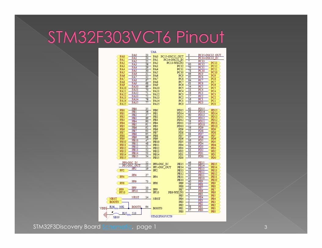
3STM32F3Discovery Board Schematic, page 1
4
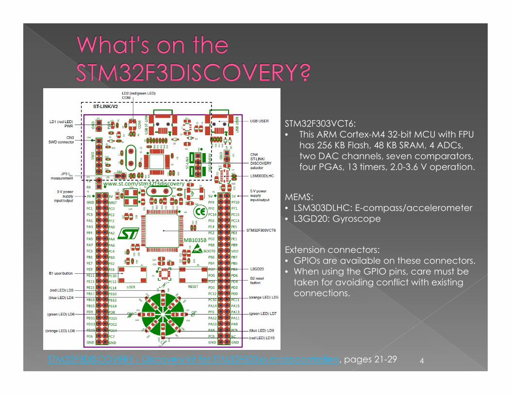
MEMS:• LSM303DLHC: E-compass/accelerometer • L3GD20: Gyroscope
STM32F303VCT6: • This ARM Cortex-M4 32-bit MCU with FPU
has 256 KB Flash, 48 KB SRAM, 4 ADCs, two DAC channels, seven comparators, four PGAs, 13 timers, 2.0-3.6 V operation.
Extension connectors:• GPIOs are available on these connectors.• When using the GPIO pins, care must be
taken for avoiding conflict with existing connections.
STM32F3DISCOVERY - Discovery kit for STM32F303xx microcontrollers, pages 21-29
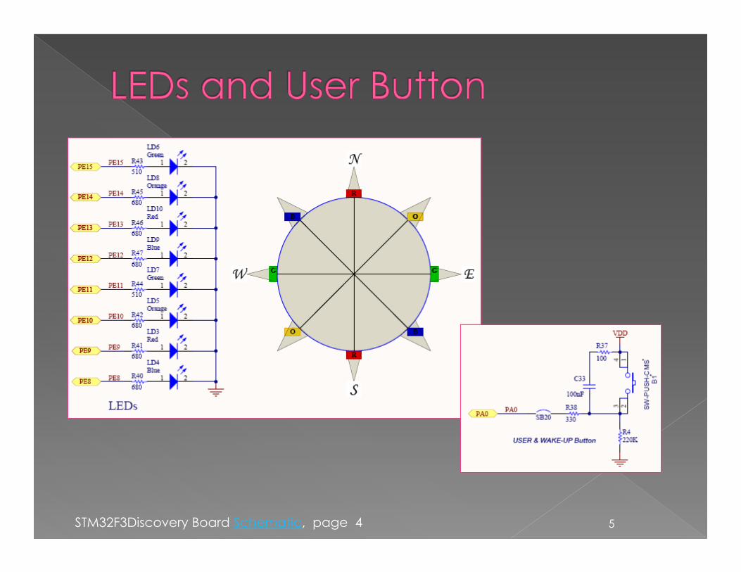
5STM32F3Discovery Board Schematic, page 4
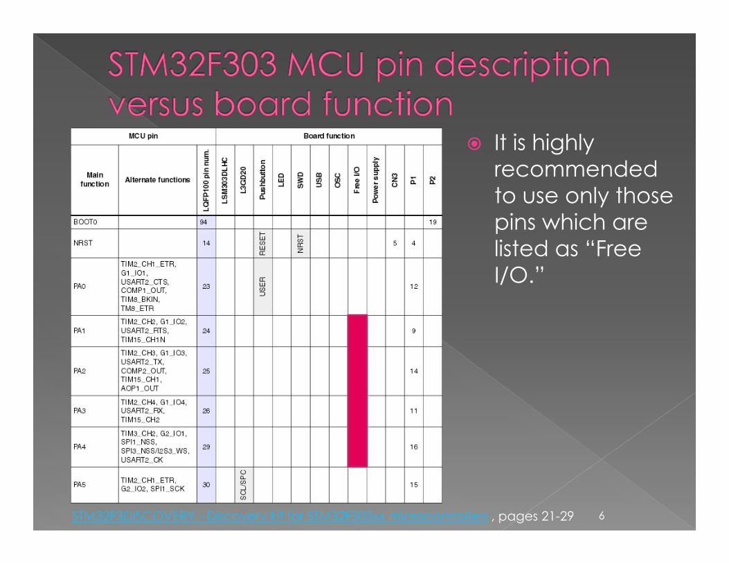
It is highly recommended to use only those pins which are listed as “Free I/O.”
6STM32F3DISCOVERY - Discovery kit for STM32F303xx microcontrollers , pages 21-29
7
AHB
2
AHB
3
AHB
1
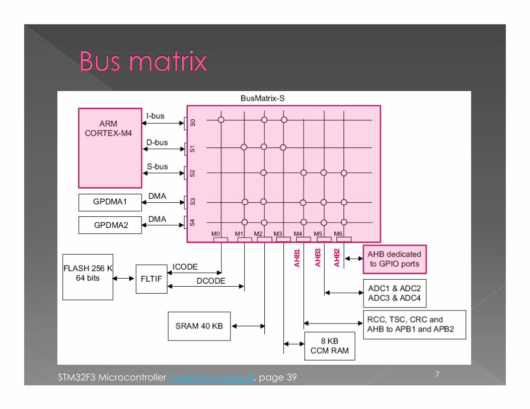
STM32F3 Microcontroller Reference Manual, page 39
CORTEX-M4CORE
Bus M
atri
x
IBus
DBus
SBus
DMA1
DMA2 AHB1
Bridge2
APB1
APB2
TIM[1,8,15,16,17]SPI1
USART1SPI1EXTI
COMPOPAMPSYSCFG
TIM[2,3,4,6,7]SPI[2,3]
USART[2,:3]UART[4:5]I2C[1,2]
CANUSB
DACIWDG
WWDGRTC
Bridge1
8
fCLK ≤ 36MHz
fCLK ≤ 72MHz
fCLK ≤ 72MHz
AHB[1;3]: Advanced High-performance Bus APB: Advanced Peripheral BusRCC: Reset and Clock Control
AHB2
AHB3
FLTIF
RAM
GPIO[A:F]
ADC[1:2]
FLASH
TSCCRCRCC
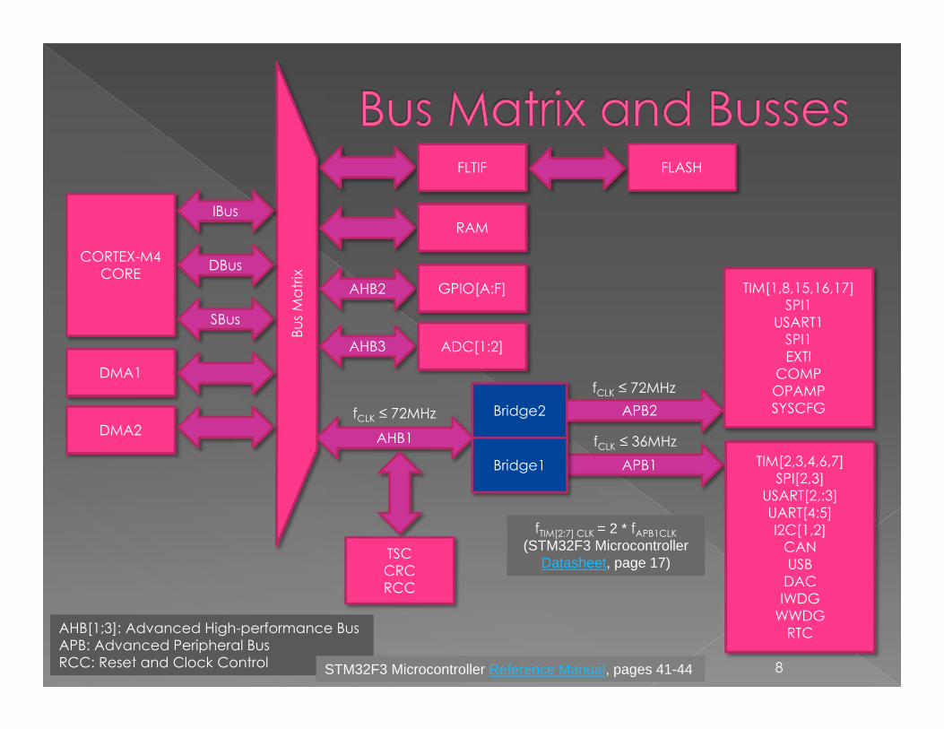
STM32F3 Microcontroller Reference Manual, pages 41-44
fTIM[2:7] CLK = 2 * fAPB1CLK (STM32F3 Microcontroller
Datasheet, page 17)
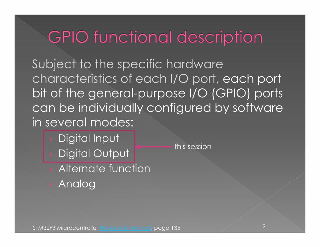
Subject to the specific hardware characteristics of each I/O port, each port bit of the general-purpose I/O (GPIO) ports can be individually configured by software in several modes:
› Digital Input › Digital Output› Alternate function› Analog
9
this session
STM32F3 Microcontroller Reference Manual, page 135
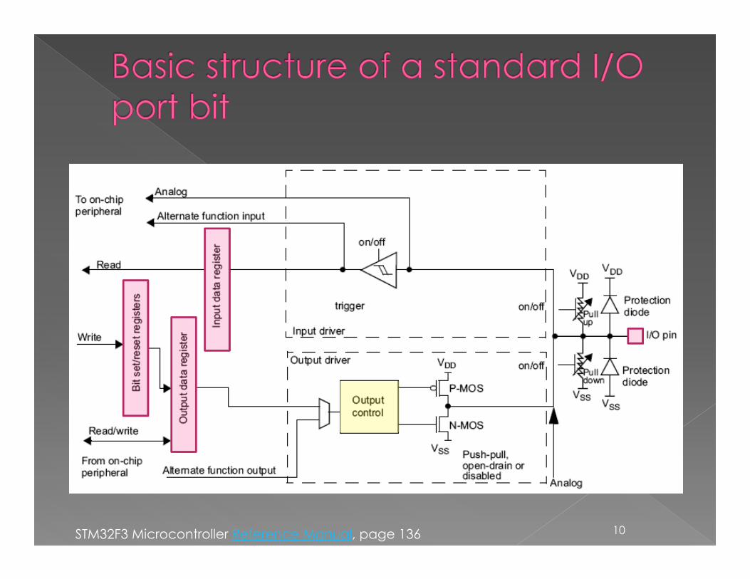
10STM32F3 Microcontroller Reference Manual, page 136
11
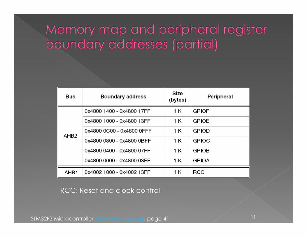
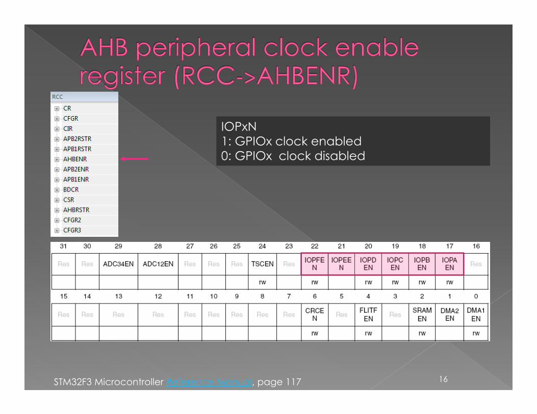
RCC: Reset and clock control
STM32F3 Microcontroller Reference Manual, page 41
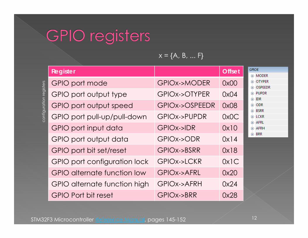
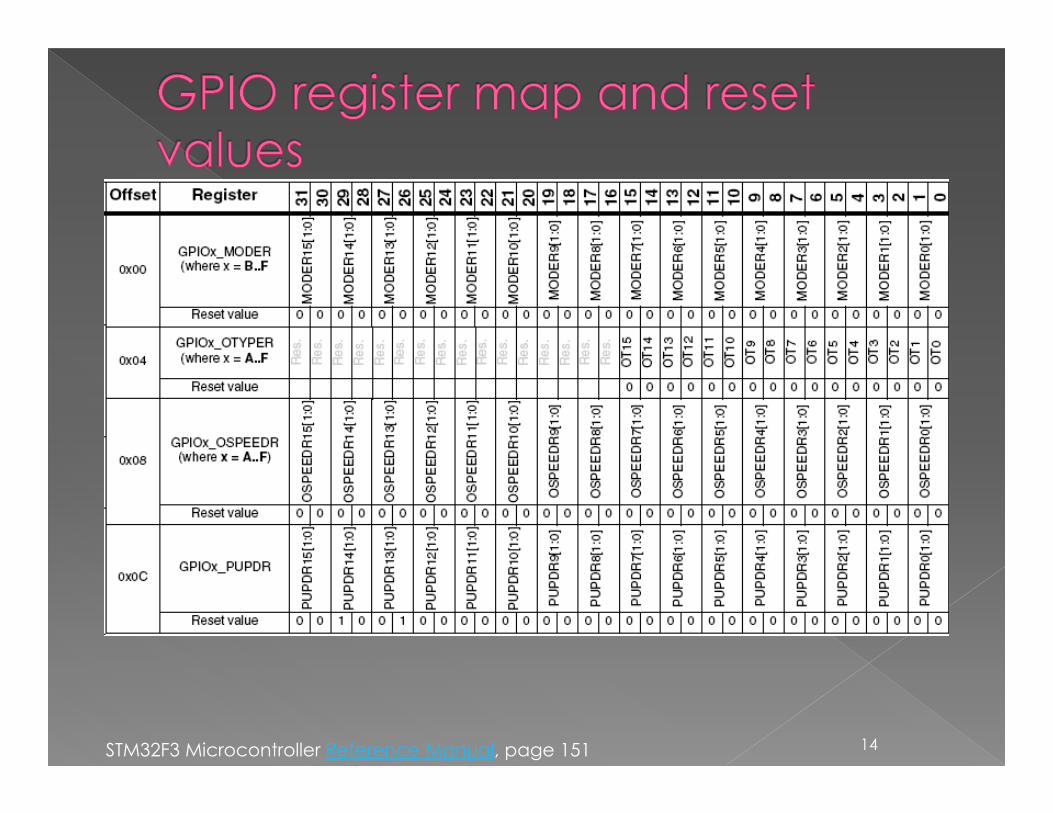
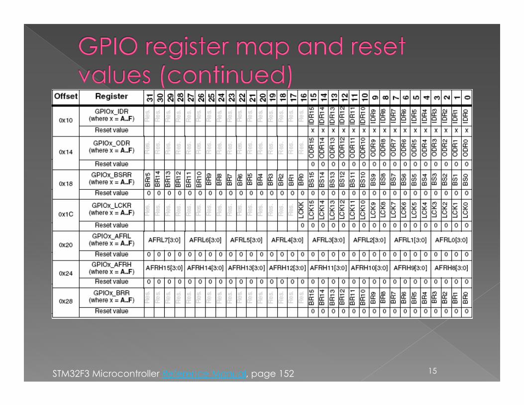
Register Offset
GPIO port mode GPIOx->MODER 0x00GPIO port output type GPIOx->OTYPER 0x04GPIO port output speed GPIOx->OSPEEDR 0x08GPIO port pull-up/pull-down GPIOx->PUPDR 0x0CGPIO port input data GPIOx->IDR 0x10GPIO port output data GPIOx->ODR 0x14GPIO port bit set/reset GPIOx->BSRR 0x18GPIO port configuration lock GPIOx->LCKR 0x1CGPIO alternate function low GPIOx->AFRL 0x20GPIO alternate function high GPIOx->AFRH 0x24GPIO Port bit reset GPIOx->BRR 0x28
12
conf
igur
atio
n re
gist
ers
STM32F3 Microcontroller Reference Manual, pages 145-152
x = {A, B, ... F}
13
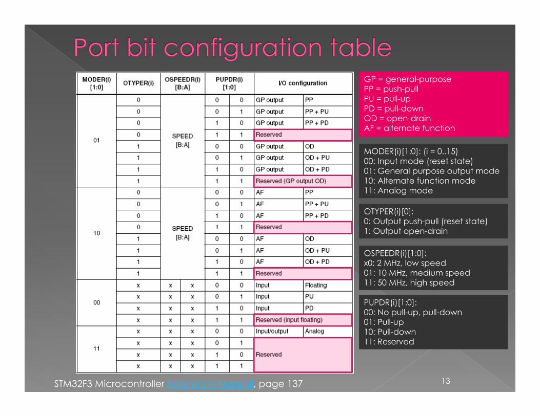
OSPEEDR(i)[1:0]:x0: 2 MHz, low speed01: 10 MHz, medium speed11: 50 MHz, high speed
GP = general-purpose PP = push-pullPU = pull-upPD = pull-downOD = open-drainAF = alternate function
STM32F3 Microcontroller Reference Manual, page 137
MODER(i)[1:0]: (i = 0..15)00: Input mode (reset state)01: General purpose output mode10: Alternate function mode11: Analog mode
OTYPER(i)[0]:0: Output push-pull (reset state)1: Output open-drain
PUPDR(i)[1:0]:00: No pull-up, pull-down01: Pull-up10: Pull-down11: Reserved
14STM32F3 Microcontroller Reference Manual, page 151
15STM32F3 Microcontroller Reference Manual, page 152
16
IOPxN1: GPIOx clock enabled0: GPIOx clock disabled
STM32F3 Microcontroller Reference Manual, page 117
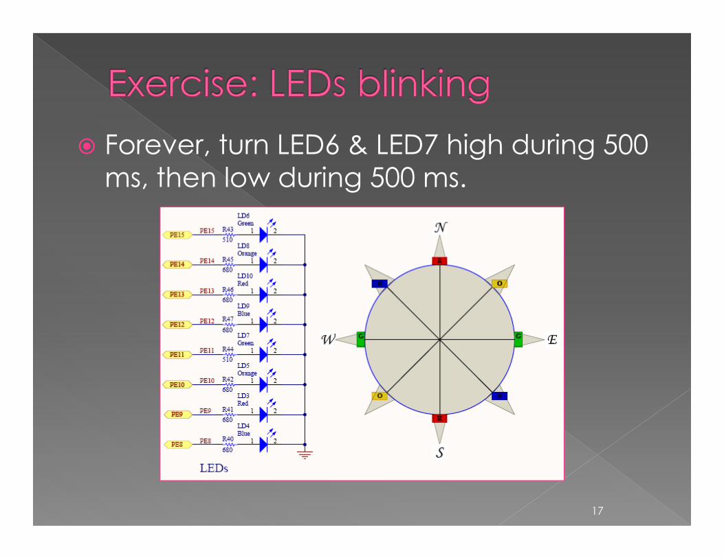
Forever, turn LED6 & LED7 high during 500 ms, then low during 500 ms.
17
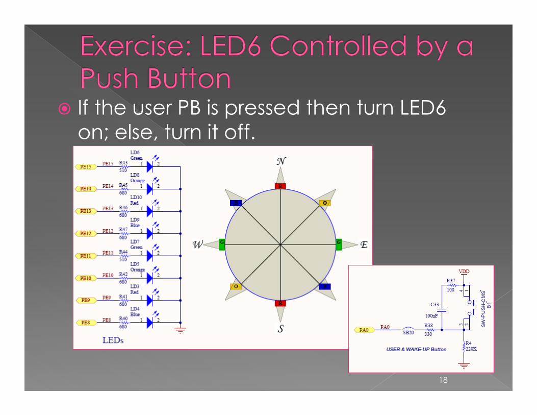
If the user PB is pressed then turn LED6 on; else, turn it off.
18
Two registers (GPIOx_AFRL, GPIO_AFRH) are provided to select one of the alternate function inputs/outputs available for each I/O. With these registers, you can connect an alternate function to some other pin as required by your application.› a number of possible peripheral functions are multiplexed
on each GPIO
19
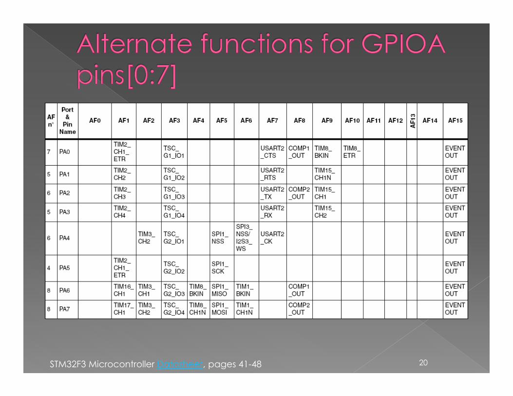
20STM32F3 Microcontroller Datasheet, pages 41-48
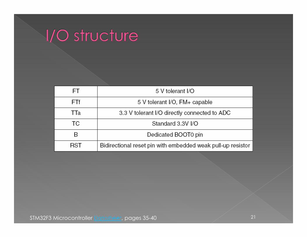
21STM32F3 Microcontroller Datasheet, pages 35-40

22