Embed Size (px)
Citation preview
Hello, and welcome to this presentation of the STM32L496G Discovery kit (32L496GDISCOVERY). It covers the main features of the Discovery board dedicated to the STM32L4 series. The demos included with the STM32L496G Discovery kit will allow you to become more familiar with this new high‐performance, ultra‐low‐power microcontroller.
1
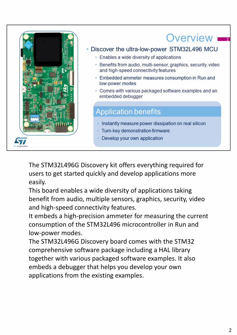
The STM32L496G Discovery kit offers everything required for users to get started quickly and develop applications more easily.This board enables a wide diversity of applications taking benefit from audio, multiple sensors, graphics, security, video and high‐speed connectivity features. It embeds a high‐precision ammeter for measuring the current consumption of the STM32L496 microcontroller in Run and low‐power modes. The STM32L496G Discovery board comes with the STM32 comprehensive software package including a HAL library together with various packaged software examples. It also embeds a debugger that helps you develop your own applications from the existing examples.
2

This is the STM32L496G Discovery board. The top side is covered by the LCD display with 2 MEMS microphones on the side, camera, STmod+/Pmod‐ pins and USB full‐speed connectors.
3
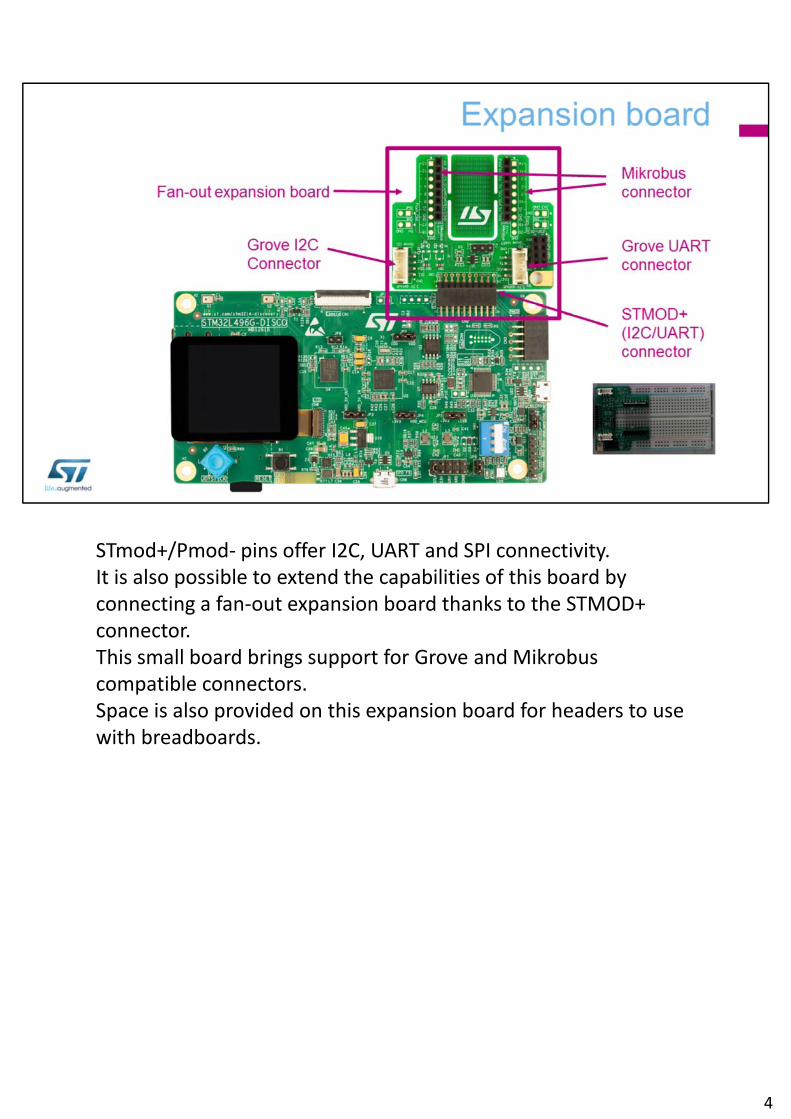
STmod+/Pmod‐ pins offer I2C, UART and SPI connectivity.It is also possible to extend the capabilities of this board byconnecting a fan‐out expansion board thanks to the STMOD+ connector.This small board brings support for Grove and Mikrobuscompatible connectors.Space is also provided on this expansion board for headers to use with breadboards.
4
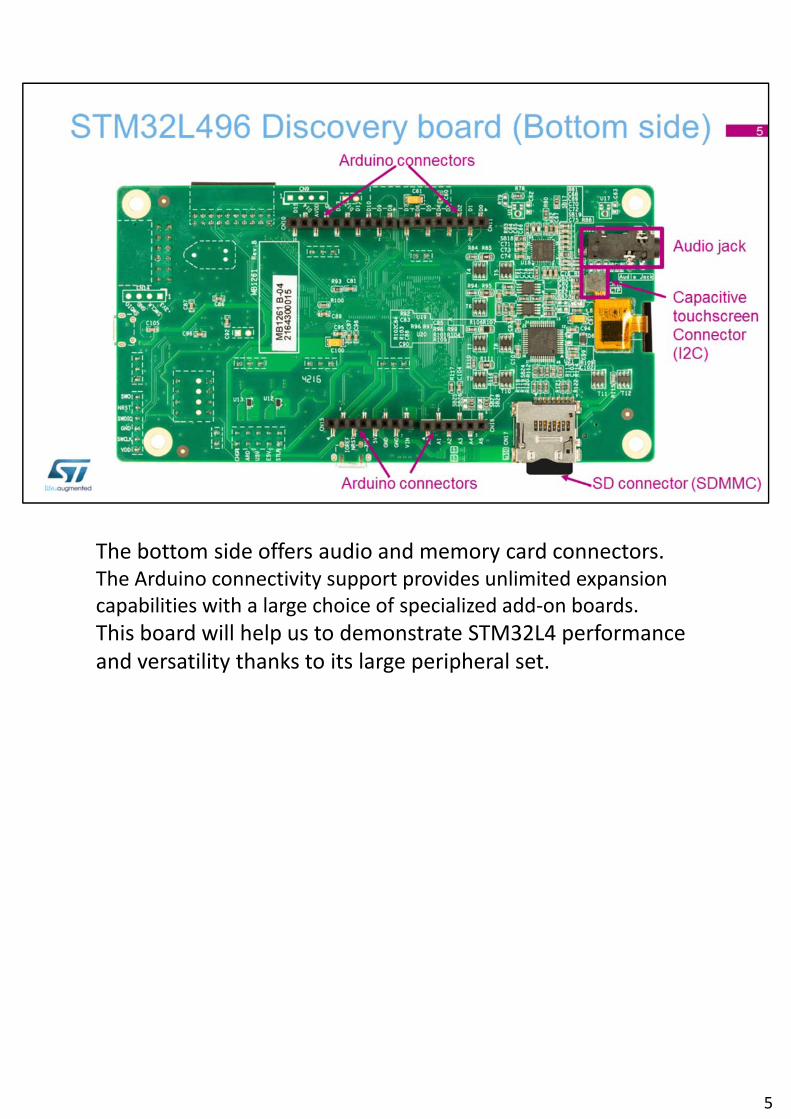
The bottom side offers audio and memory card connectors.The Arduino connectivity support provides unlimited expansion capabilities with a large choice of specialized add‐on boards.
This board will help us to demonstrate STM32L4 performance and versatility thanks to its large peripheral set.
5
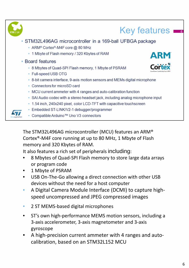
The STM32L496AG microcontroller (MCU) features an ARM® Cortex®‐M4F core running at up to 80 MHz, 1 Mbyte of Flash memory and 320 Kbytes of RAM.
It also features a rich set of peripherals including:• 8 Mbytes of Quad‐SPI Flash memory to store large data arrays
or program code• 1 Mbyte of PSRAM• USB On‐The‐Go allowing a direct connection with other USB
devices without the need for a host computer
• A Digital Camera Module Interface (DCMI) to capture high‐speed uncompressed and JPEG compressed images
• 2 ST MEMS‐based digital microphones
• ST’s own high‐performance MEMS motion sensors, including a 3‐axis accelerometer, 3‐axis magnetometer and 3‐axis gyroscope
• A high‐precision current ammeter with 4 ranges and auto‐calibration, based on an STM32L152 MCU
6

• A Serial Audio Interface with a stereo headset jack, including analog microphone input
• A 1.54 inch, 240x240 pixel, TFT color LCD • An embedded ST‐LINK/V2‐1 debugger/programmer for
connecting your favorite development tools• Compatible Arduino™ Uno V3 connectors
This board incorporates 3 distinct STM32 devices: the target, the debugger and the MCU used to measure the current.
6
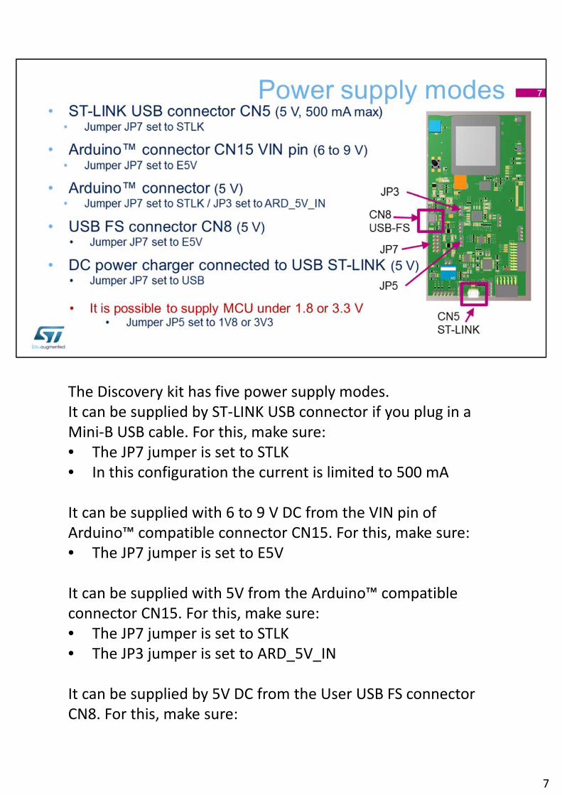
The Discovery kit has five power supply modes.It can be supplied by ST‐LINK USB connector if you plug in a Mini‐B USB cable. For this, make sure: • The JP7 jumper is set to STLK• In this configuration the current is limited to 500 mA
It can be supplied with 6 to 9 V DC from the VIN pin of Arduino™ compatible connector CN15. For this, make sure: • The JP7 jumper is set to E5V
It can be supplied with 5V from the Arduino™ compatible connector CN15. For this, make sure: • The JP7 jumper is set to STLK• The JP3 jumper is set to ARD_5V_IN
It can be supplied by 5V DC from the User USB FS connector CN8. For this, make sure:
7
• The JP7 jumper is set to E5V
It can be supplied by 5V DC power charger connected to USB ST‐LINK (CN5). For this, make sure: • The JP7 jumper is set to USB
Please note that it is possible to supply the MCU under 1.8V or 3.3V by setting the JP5 jumper accordingly.
7
Now, let's look at the demos included in the STM32L496G Discovery kit.
8
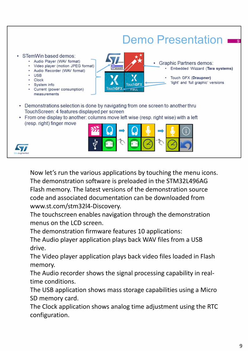
Now let’s run the various applications by touching the menu icons.The demonstration software is preloaded in the STM32L496AG Flash memory. The latest versions of the demonstration source code and associated documentation can be downloaded from www.st.com/stm32l4‐Discovery.The touchscreen enables navigation through the demonstration menus on the LCD screen.The demonstration firmware features 10 applications:The Audio player application plays back WAV files from a USB drive.The Video player application plays back video files loaded in Flash memory.The Audio recorder shows the signal processing capability in real‐time conditions.The USB application shows mass storage capabilities using a Micro SD memory card.The Clock application shows analog time adjustment using the RTC configuration.
9
The Current consumption application measures and displays the MCU consumption depending on the selected power mode.The System info menu displays various board information such as firmware version, CPU speed and core type.3 partners Graphic application demonstrates the graphics capabilities of the platform (Embedded Wizzard from Tara Systems, Touch GFX in “light” and “full graphic” version from Draupner).
9
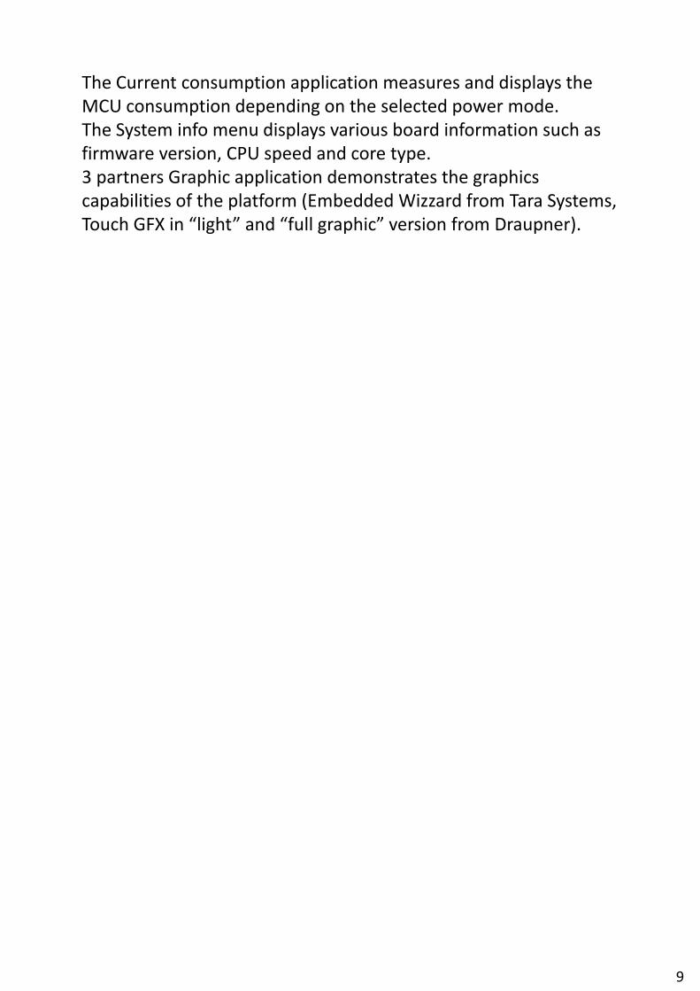
The PLAYER application plays back WAV files stored in the microSD memory card. It uses a CS42L51 audio codec to output the audio data on the 3.5 mm jack. Earphone volume can be adjusted during playback.
10
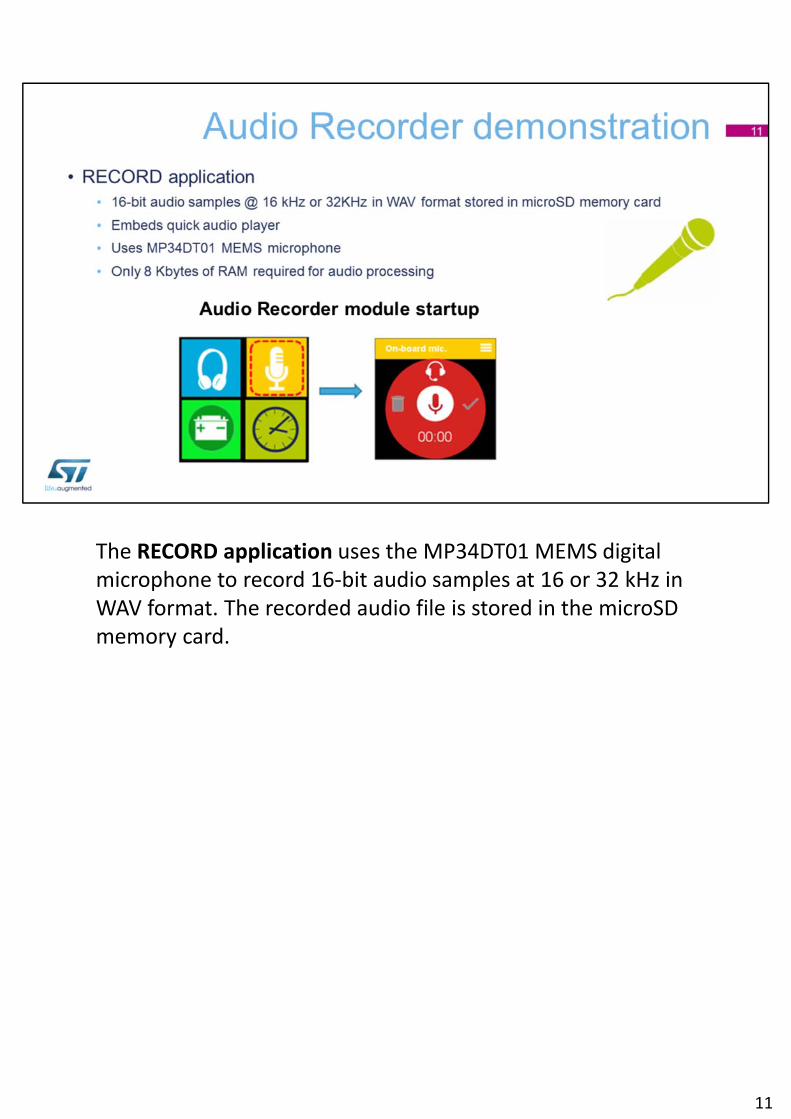
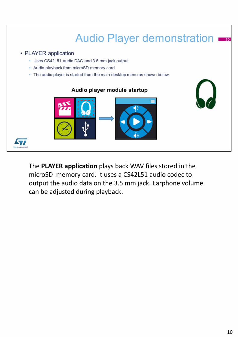
The RECORD application uses the MP34DT01 MEMS digital microphone to record 16‐bit audio samples at 16 or 32 kHz in WAV format. The recorded audio file is stored in the microSD memory card.
11
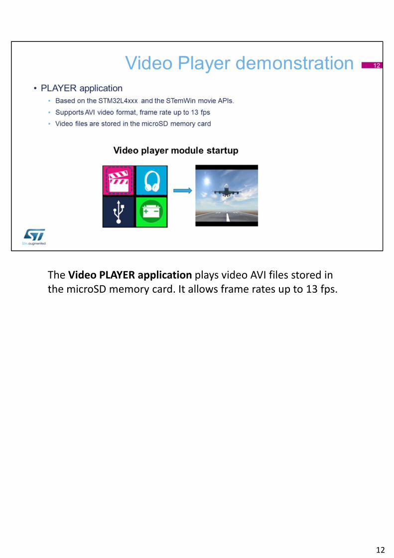
The Video PLAYER application plays video AVI files stored in the microSD memory card. It allows frame rates up to 13 fps.
12
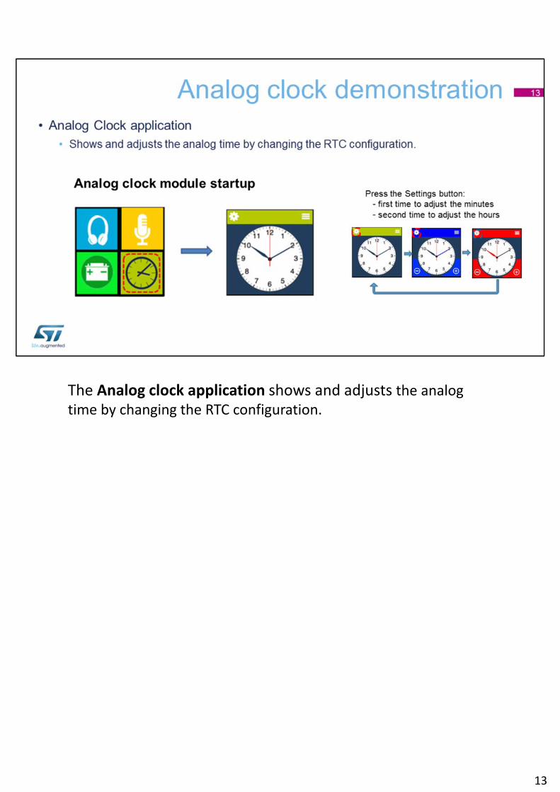
The Analog clock application shows and adjusts the analog time by changing the RTC configuration.
13
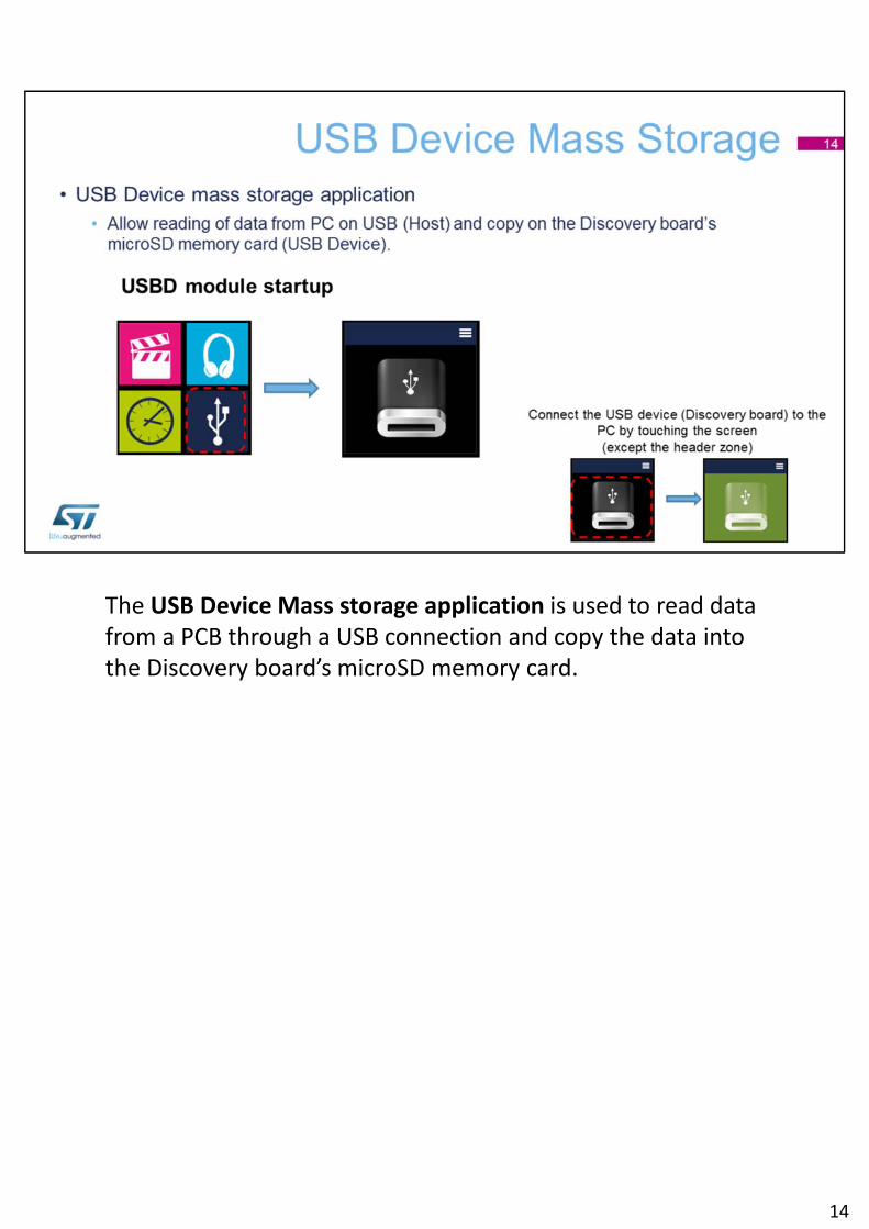
The USB Device Mass storage application is used to read data from a PCB through a USB connection and copy the data into the Discovery board’s microSD memory card.
14
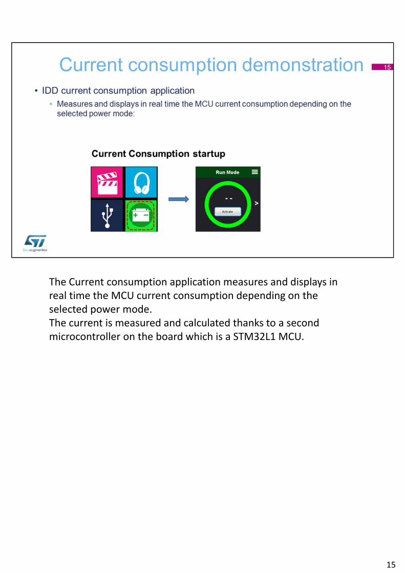
The Current consumption application measures and displays in real time the MCU current consumption depending on the selected power mode.The current is measured and calculated thanks to a second microcontroller on the board which is a STM32L1 MCU.
15
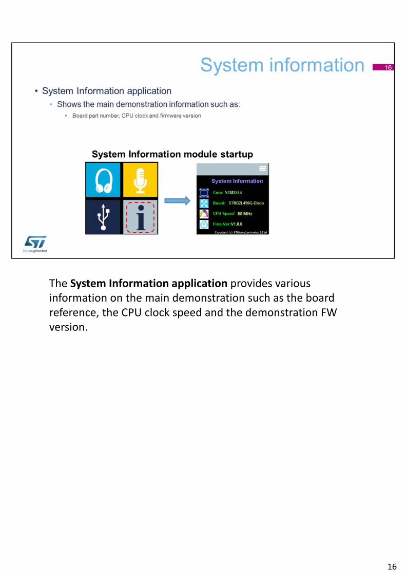
The System Information application provides various information on the main demonstration such as the board reference, the CPU clock speed and the demonstration FW version.
16
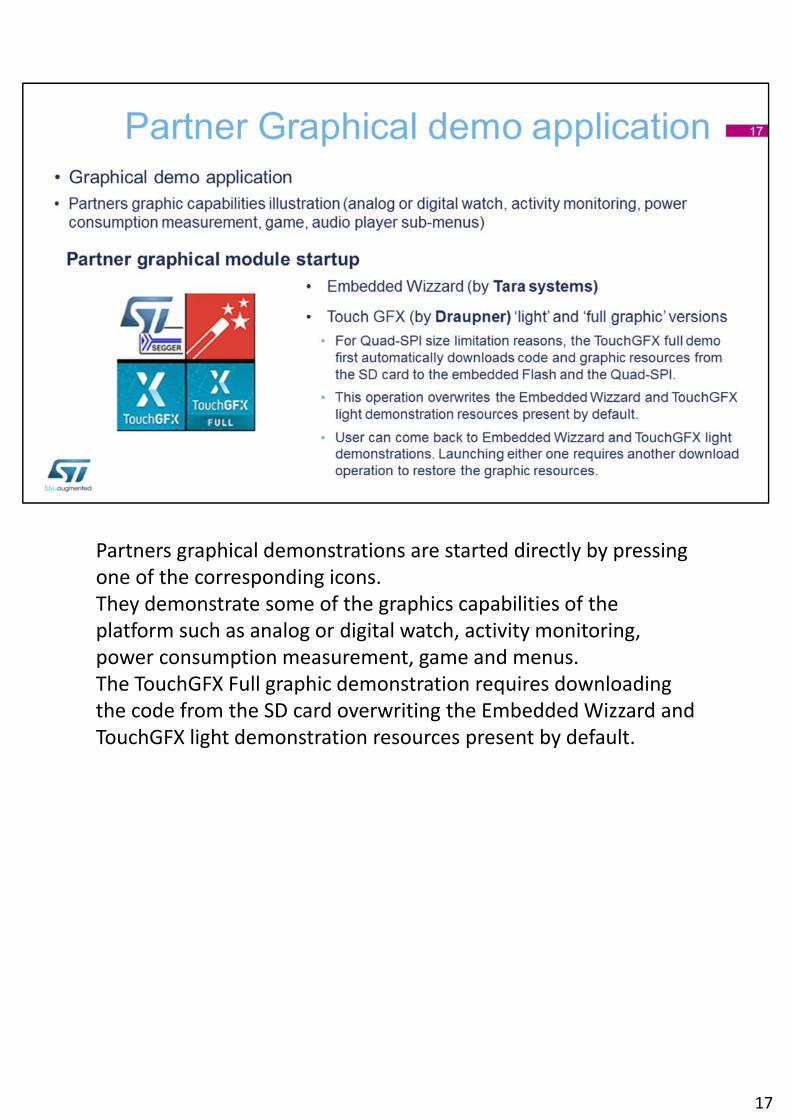
Partners graphical demonstrations are started directly by pressing one of the corresponding icons.They demonstrate some of the graphics capabilities of the platform such as analog or digital watch, activity monitoring, power consumption measurement, game and menus.The TouchGFX Full graphic demonstration requires downloading the code from the SD card overwriting the Embedded Wizzard and TouchGFX light demonstration resources present by default.
17
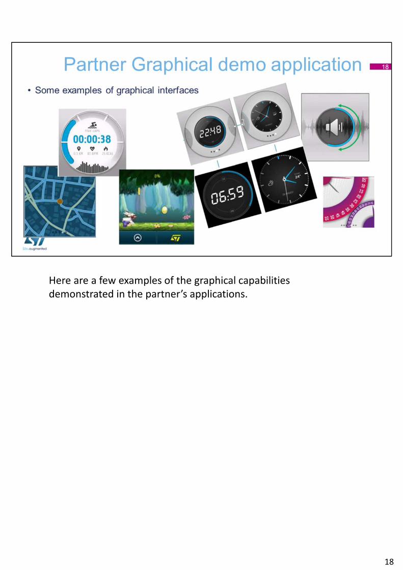
Here are a few examples of the graphical capabilitiesdemonstrated in the partner’s applications.
18
For more information on the ultra‐low‐power STM32L496G Discovery kit, visit www.st.com/STM32L4‐DISCOVERY. You can also watch our videos on our YouTube channel.
Thank you.
19