Embed Size (px)
Citation preview
St.MARTIN’S ENGINEERING COLLEGE Dhulapally, Secunderabad-500 014
Subject: Machine Drawing Class : MECH-II
Questions
PART-A
1 Sektch the conventional representation of the following materials:(a).Metals, (b).Glass, (c) Packing (d).Insulating material (e).Liquids, (f). Wood, (g).Concrete
2
Sketch the conventional representation of the following: (a)Splined shafts (b) Interrupted (c) leaf spring with eyes, (d) Cylindrical compression spring, (e)Cylindrical tension spring
3 Sketch the conventional representation of the following: (a).Spur gear and (b) helical gear.(c).Bevel gear (d) Worm wheel (e) Worm and (f).Straight knurling
4
Sketch the following thread profiles for a pitch 30 mm and give their applications: (a).BSW thread, (b) Buttress thread (c) Square thread,(d) ACME thread and (e) Worm thread.
5 Give the proportions of a hexagonal nut, in terms of the nominal diameter of the bolt of 20 mm.
6 Draw the three views of a hexagonal headed bolt of nominal diameter 25 mm and length 100 mm; with a hexagonal nut and washer.
7 Following foundation bolts of diameter 25 mm: (a).eye foundation bolt, (b). Bent foundation bolt, (c). Rag foundation bolt and (d) Lewis foundation bolt.
8 Draw the sectional view from the front, and view from the side of a cotter joint with sleeve used to connect two rods of 30 mm diameter each.
9
Draw the half sectional view from the front, with top half in section and the view from the side of a cotter joint with socket and spigot ends, to connect two rods of 30 mm diameter each.
10 Sketch the sectional view from the front and view from the side of a butt- muff coupling; indicating proportions for connecting two shafts, each of diameter 30 mm.
11
Draw (a) half sectional view from the front, top half in section and (b) half sectional view from the side, left half in section, of a split-muff coupling, indicating proportions to connect two shafts, each of diameter 50 mm.
12 Draw (a) half sectional view from the front, top half in section and (b) view from the side of a rigid flange coupling to connect two shafts, each of diameter 30 mm
13
Draw (a) half sectional view from the front, top half in section and (b) view from the side of a bushed pin type flange coupling, indicating proportions to connect two shafts, each of diameter 30 mm.
14 Draw (a) sectional view from the front and (b) view from the side of a universal coupling, indicating proportions, to connect two shafts, each of diameter 30 mm.
15 Sketch the required views of (a) ldham coupling and (b) cushion coupling, indicating proportions, used to connect two shafts, each of diameter 30 mm.
16
Draw the following views of a plummer block, suitable for supporting a shaft of diameter 50mm: (a) half sectional view from the front, with left half in section, (b) sectional view from the side, and view from above.
17 Sketch the necessary views of a foot-step bearing, for supporting a shaft of diameter 50mm. Give all important proportionate dimensions.
18 Giving proportionate dimensions, sketch any four forms of commonly used rivet heads, choosing the rivet diameter as 10 mm.
19
Draw (a) sectional view from the front and (b) view from above, of the following riveted joints, to join plates of thickness 10 mm: (i).Single riveted lap joint, (ii) double riveted chain lap joint, (iii) double riveted zig- zag lap joint,
20
Draw (a) sectional view from the front and (b) view from above, of the following riveted joints, to join plates of thickness 10 mm: (i) single riveted, single strap butt joint, (ii) single riveted, double strap butt joint (iii) double riveted, double strap, chain butt joint and (iv) double riveted, double strap, zig-zag butt joint.
21 Draw the half sectional view from the front, with top view knuckle joint , to connect two rods of 30 mm diameter each
PART-B
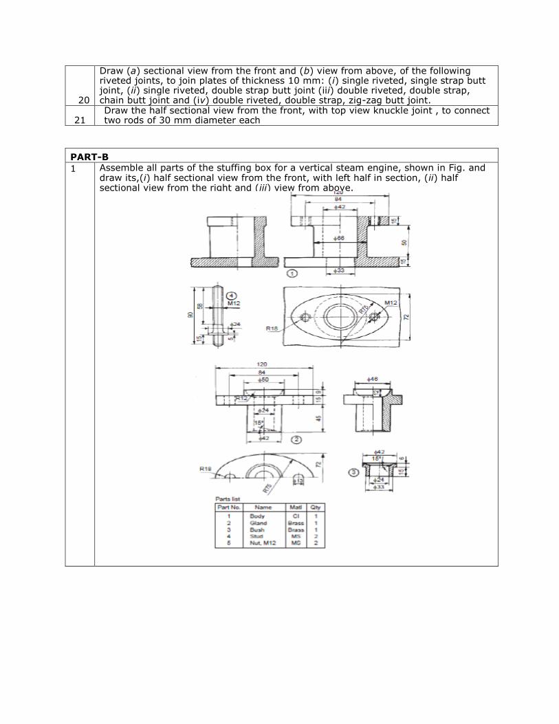
1 Assemble all parts of the stuffing box for a vertical steam engine, shown in Fig. and draw its,(i) half sectional view from the front, with left half in section, (ii) half sectional view from the right and (iii) view from above.
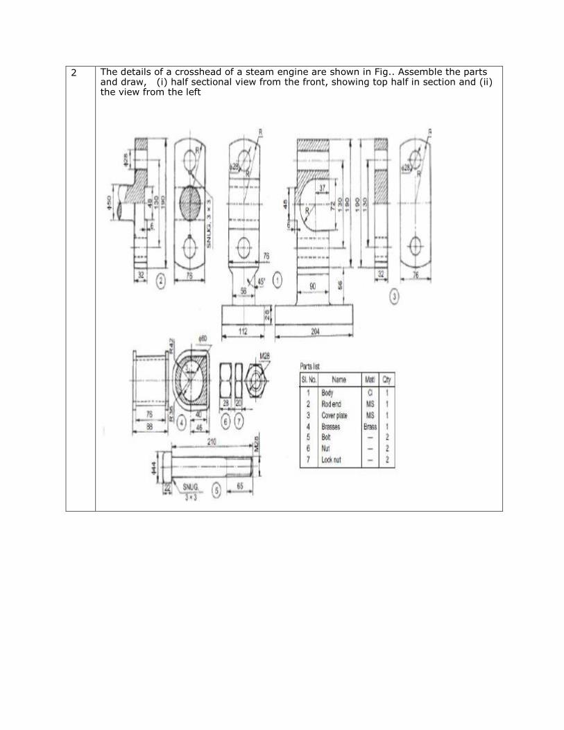
2 The details of a crosshead of a steam engine are shown in Fig.. Assemble the parts and draw, (i) half sectional view from the front, showing top half in section and (ii) the view from the left
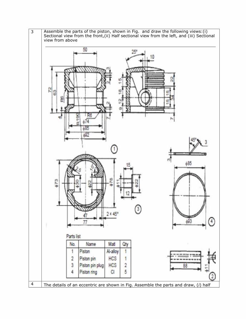
3 Assemble the parts of the piston, shown in Fig. and draw the following views:(i) Sectional view from the front,(ii) Half sectional view from the left, and (iii) Sectional view from above
4 The details of an eccentric are shown in Fig. Assemble the parts and draw, (i) half
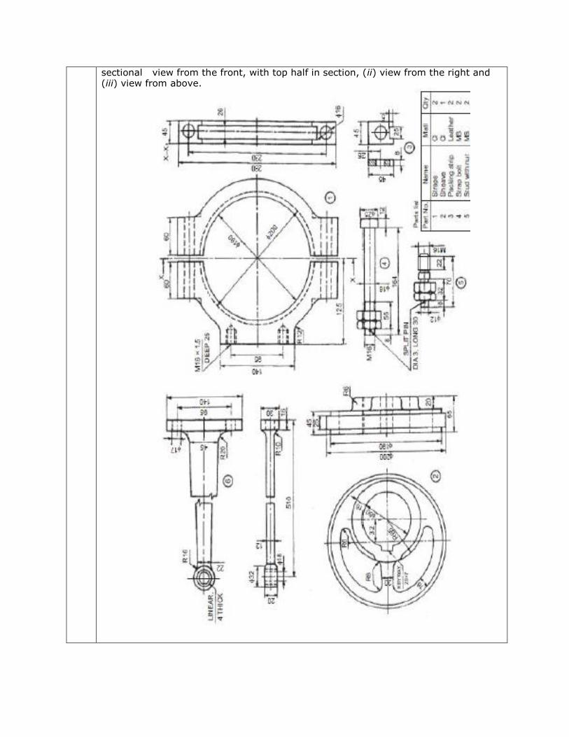
sectional view from the front, with top half in section, (ii) view from the right and (iii) view from above.
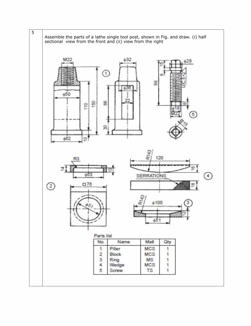
5 Assemble the parts of a lathe single tool post, shown in Fig. and draw. (i) half sectional view from the front and (ii) view from the right
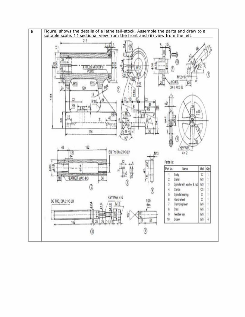
6 Figure, shows the details of a lathe tail-stock. Assemble the parts and draw to a suitable scale, (i) sectional view from the front and (ii) view from the left.
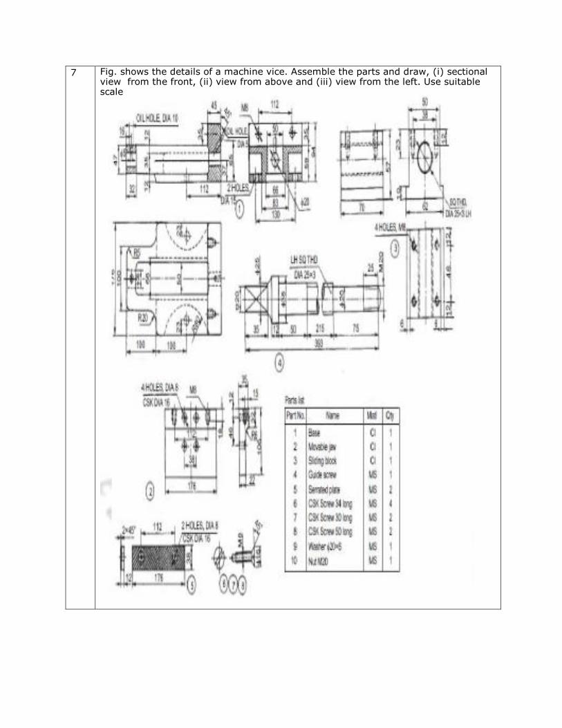
7 Fig. shows the details of a machine vice. Assemble the parts and draw, (i) sectional view from the front, (ii) view from above and (iii) view from the left. Use suitable scale
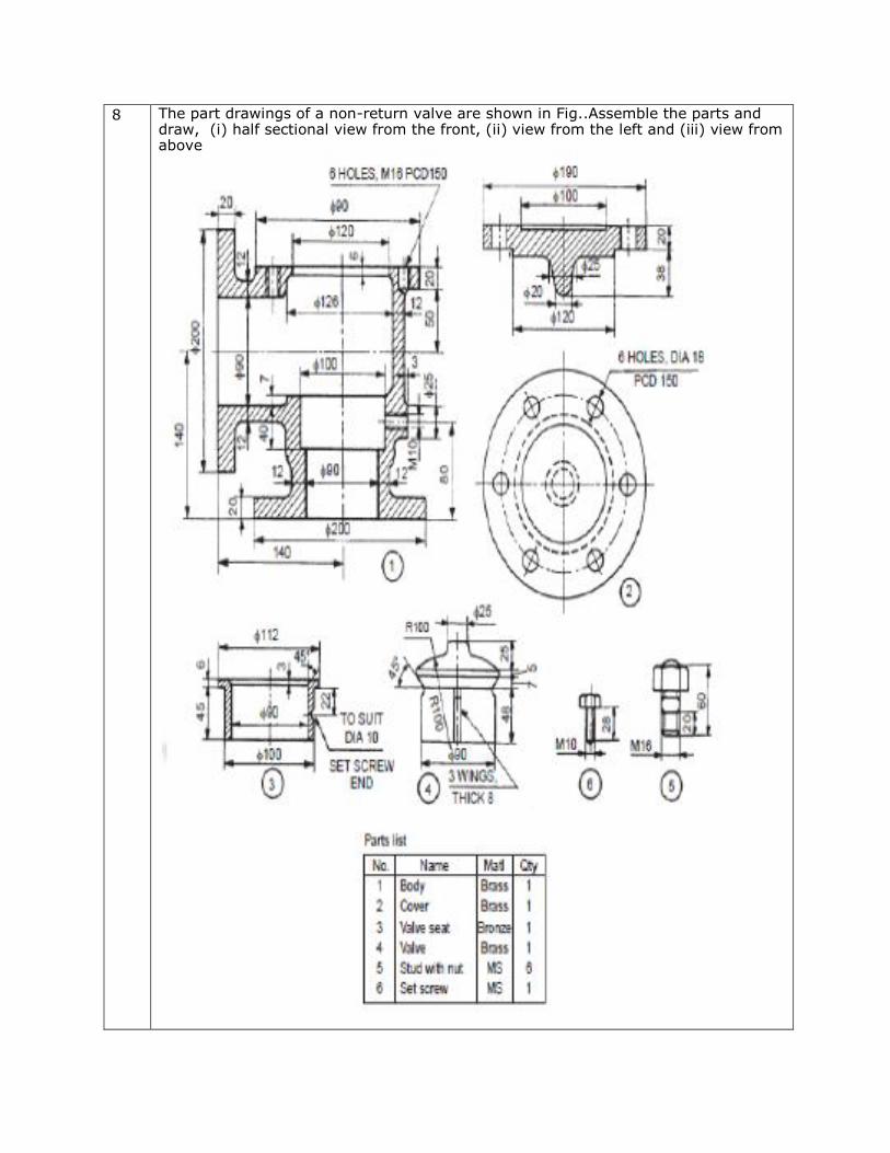
8 The part drawings of a non-return valve are shown in Fig..Assemble the parts and draw, (i) half sectional view from the front, (ii) view from the left and (iii) view from above
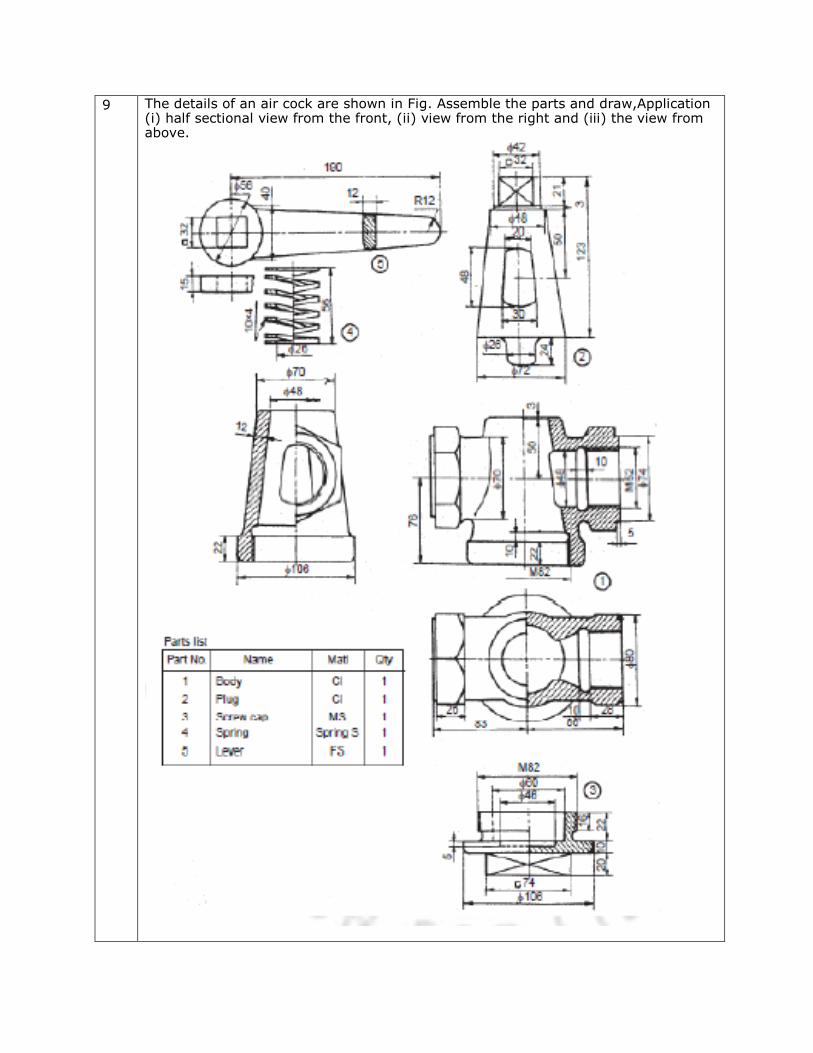
9 The details of an air cock are shown in Fig. Assemble the parts and draw,Application (i) half sectional view from the front, (ii) view from the right and (iii) the view from above.
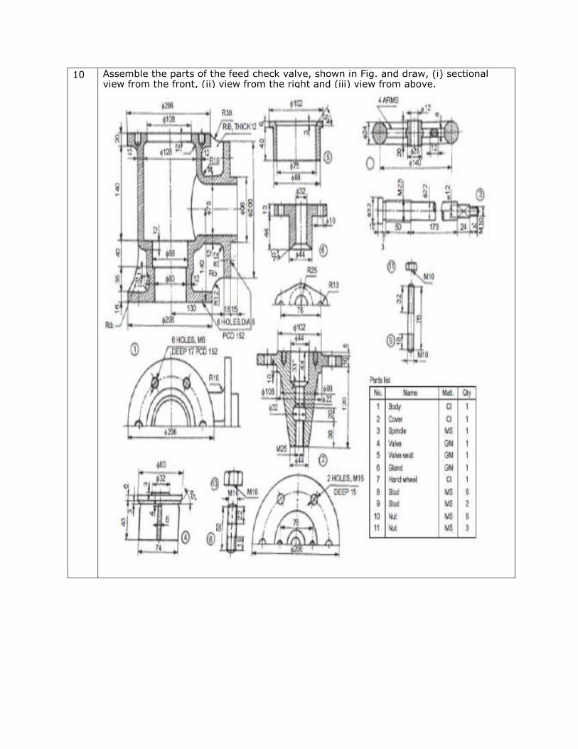
10 Assemble the parts of the feed check valve, shown in Fig. and draw, (i) sectional view from the front, (ii) view from the right and (iii) view from above.
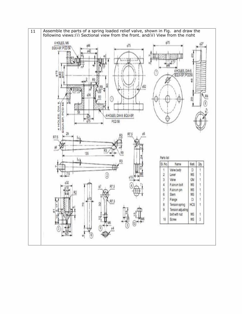
11 Assemble the parts of a spring loaded relief valve, shown in Fig. and draw the following views:(i) Sectional view from the front, and(ii) View from the right
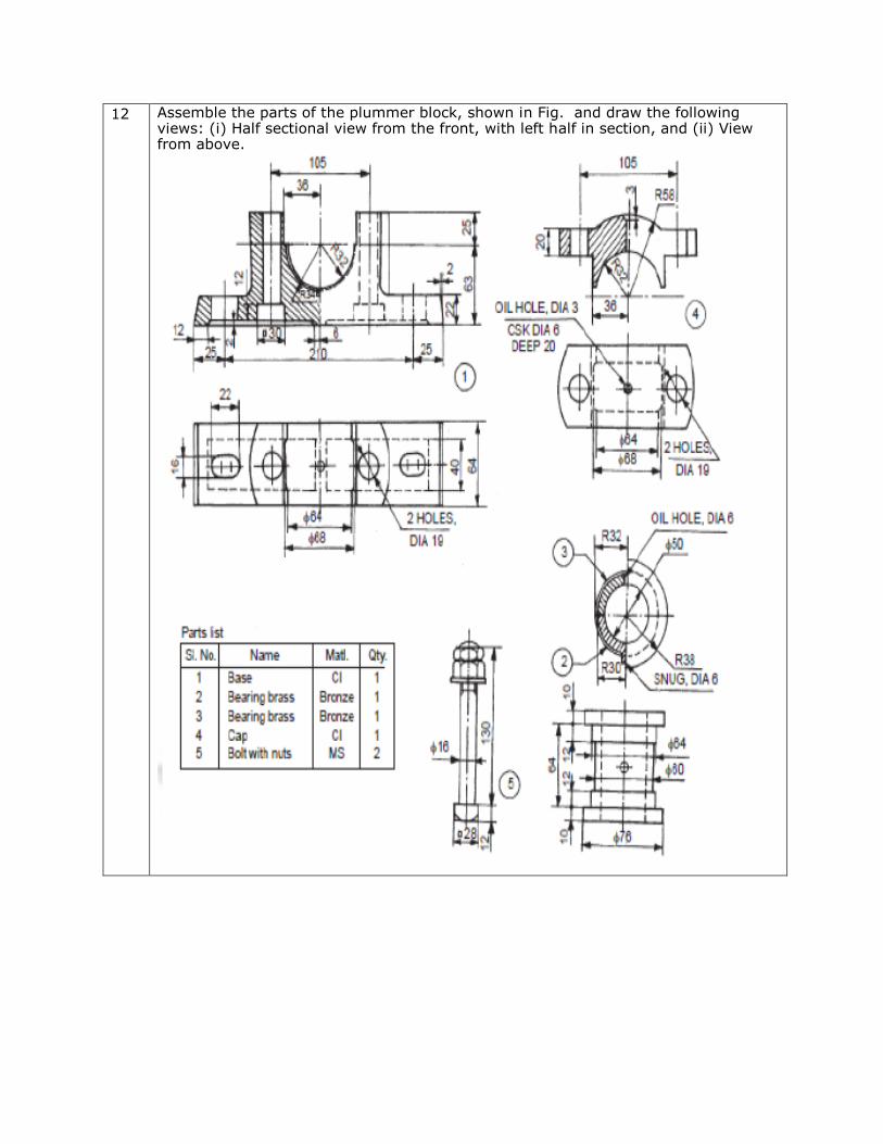
12 Assemble the parts of the plummer block, shown in Fig. and draw the following views: (i) Half sectional view from the front, with left half in section, and (ii) View from above.
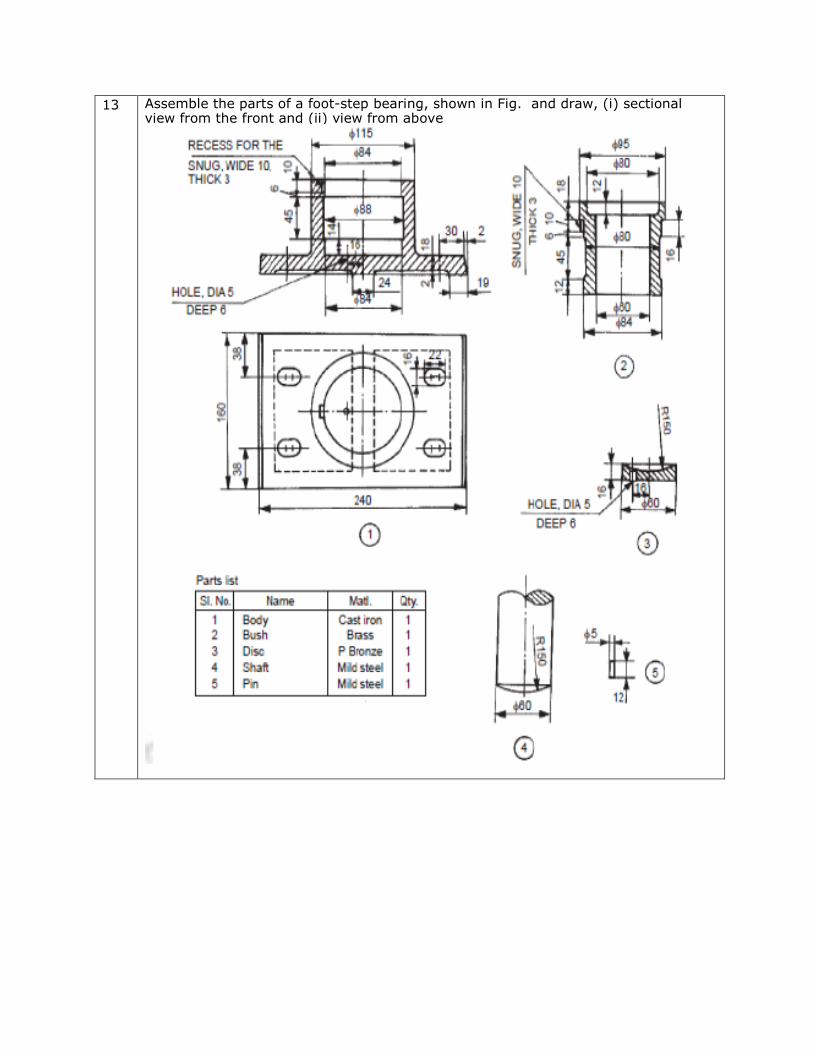
13 Assemble the parts of a foot-step bearing, shown in Fig. and draw, (i) sectional view from the front and (ii) view from above
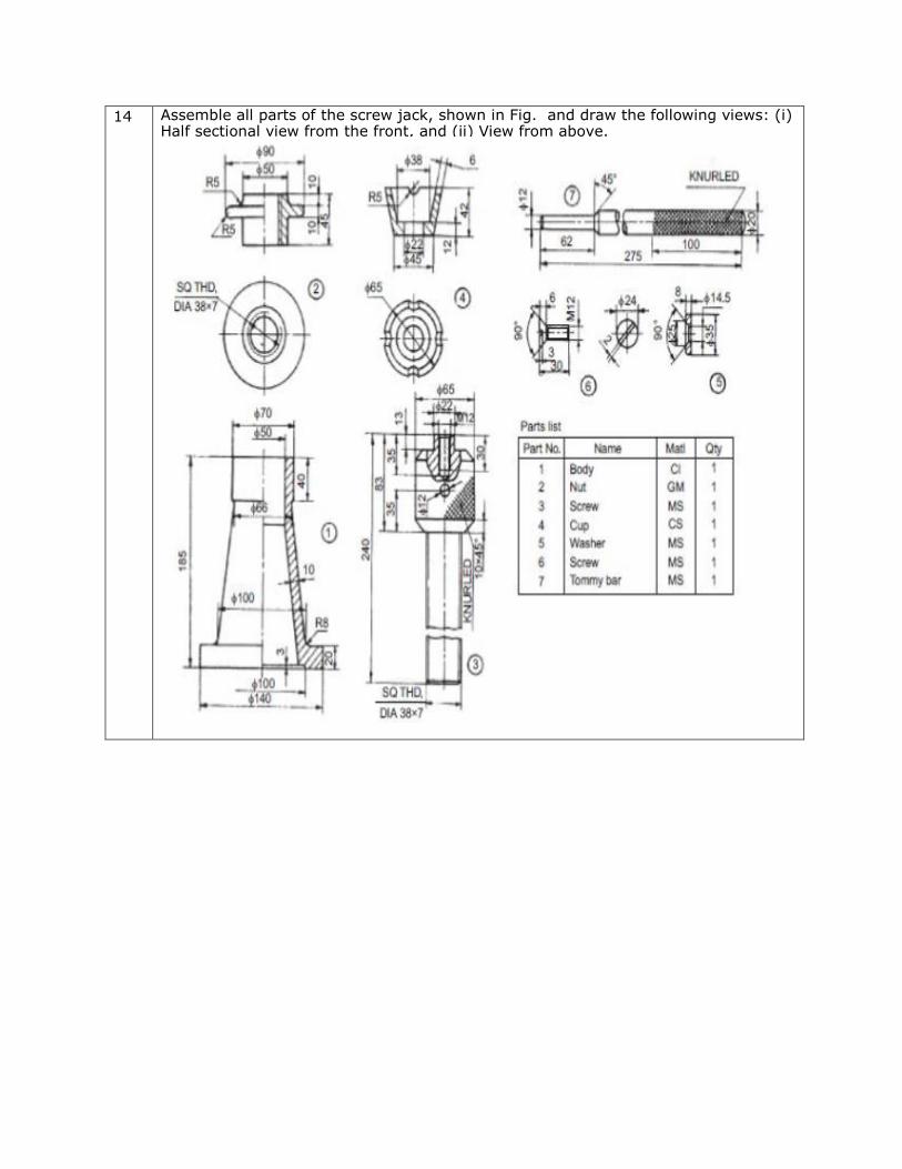
14 Assemble all parts of the screw jack, shown in Fig. and draw the following views: (i) Half sectional view from the front, and (ii) View from above.
PART-C
1 Sektch the conventional representation of the following materials:(a).Metals, (b).Glass, (c) Packing (d).Insulating material (e).Liquids, (f). Wood, (g).Concrete
2 Sketch the following thread profiles for a pitch 30 mm and give their applications: (a).BSW thread, (b) Buttress thread (c) Square thread,(d) ACME thread and (e) Worm thread.
3 Give the proportions of a hexagonal nut, in terms of the nominal diameterof the bolt of 20 mm.
4 Following foundation bolts of diameter 25 mm: (a).eye foundation bolt, (b). Bent foundation bolt, (c). Rag foundation bolt and (d) Lewis foundation bolt.
5 Draw the sectional view from the front, and view from the side of a cotter joint with sleeve used to connect two rods of 30 mm diameter each.
6 Draw the half sectional view from the front, with top view knuckle joint , to connect two rods of 30 mm diameter each
7 Draw (a) sectional view from the front and (b) view from the side of a universal coupling, indicating proportions, to connect two shafts, each of diameter 30 mm.
8 Draw (a) sectional view from the front and (b) view from above, of the following riveted joints, to join plates of thickness 10 mm: (i).Single riveted lap joint, (ii) double riveted chain lap joint, (iii) double riveted zig-zag lap joint,
9
Draw (a) sectional view from the front and (b) view from above, of the following riveted joints, to join plates of thickness 10 mm: (i) single riveted, single strap butt joint, (ii) single riveted, double strap butt joint (iii) double riveted, double strap, chain butt joint and (iv) double riveted, double strap, zig-zag butt joint.
PART-D
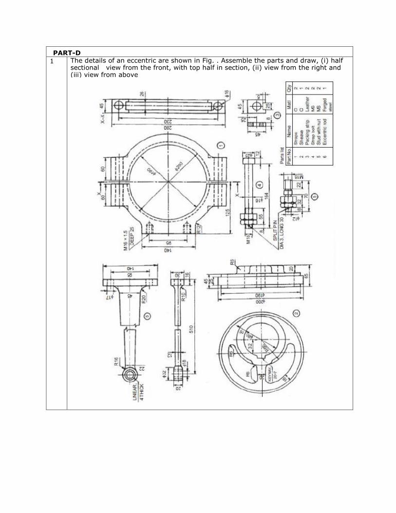
1 The details of an eccentric are shown in Fig. . Assemble the parts and draw, (i) half sectional view from the front, with top half in section, (ii) view from the right and (iii) view from above
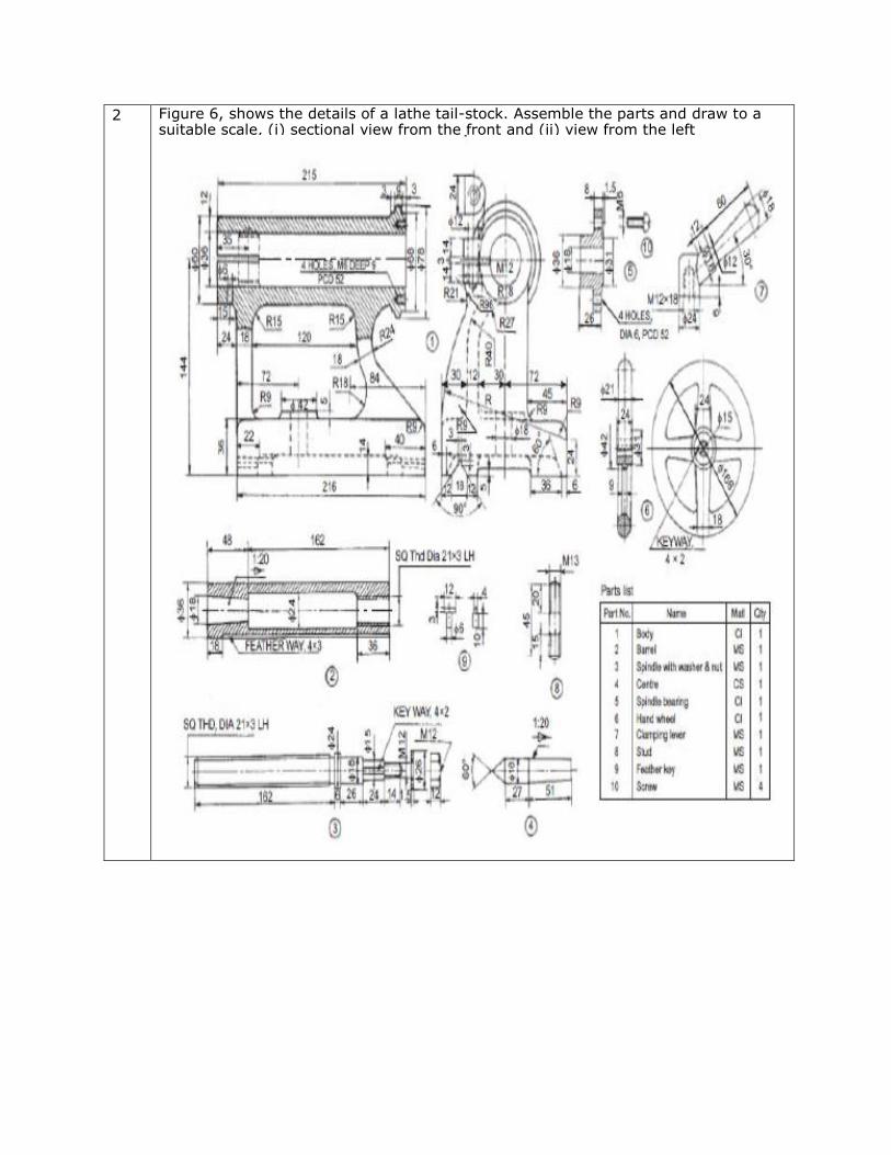
2 Figure 6, shows the details of a lathe tail-stock. Assemble the parts and draw to a suitable scale, (i) sectional view from the front and (ii) view from the left
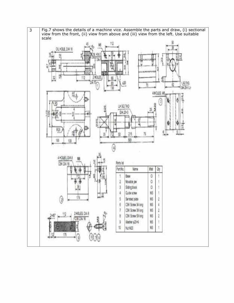
3 Fig.7 shows the details of a machine vice. Assemble the parts and draw, (i) sectional view from the front, (ii) view from above and (iii) view from the left. Use suitable scale
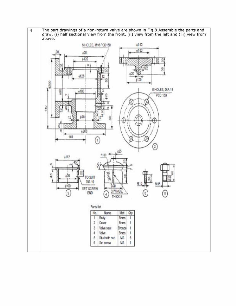
4 The part drawings of a non-return valve are shown in Fig.8.Assemble the parts and draw, (i) half sectional view from the front, (ii) view from the left and (iii) view from above.
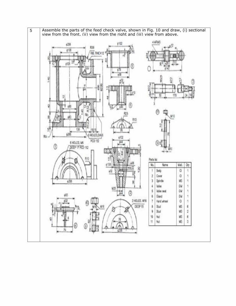
5 Assemble the parts of the feed check valve, shown in Fig. 10 and draw, (i) sectional view from the front, (ii) view from the right and (iii) view from above.