Embed Size (px)
Citation preview

ISSN (Online) : 2319 - 8753 ISSN (Print) : 2347 - 6710
International Journal of Innovative Research in Science, Engineering and Technology
Volume 3, Special Issue 3, March 2014
2014 International Conference on Innovations in Engineering and Technology (ICIET’14)
On 21st& 22nd March Organized by
K.L.N. College of Engineering, Madurai, Tamil Nadu, India
Copyright to IJIRSET www.ijirset.com 1330
M.R. Thansekhar and N. Balaji (Eds.): ICIET’14
Stress Intensity Factor Determination of
Multiple Straight and Oblique Cracks in Double
Cover Butt Riveted Joint
Gokul.R1, Dhayananth.S
2, Adithya.V
3, S.Suresh Kumar
4
UG Mechanical 3rd
year students, S.S.N. College of Engineering, Kalavakkam, Chennai, India1, 2, 3
Associate Professor, Mechanical, S.S.N. College of Engineering, Kalavakkam, Chennai, India4
ABSTRACT—In real life, components are subjected to
cracking at many vulnerable locations such as the rivet holes.
However, we do not consider for the presence of multiple
cracks. Unlike components with a single crack, the behavior
of these components under tension cannot be predicted. When
two cracks approach one another, their stress fields influence
each other and produce enhancing or shielding effect
depending on the position of the cracks. In the present work,
stress intensity factor (SIF) solution of multiple straight and
oblique cracks in a rivet hole is considered. Crack depth ratios
(a/t) of 0.1, 0.15 and 0.2 have been considered for both
straight and inclined cracks. SIF solution of single and
multiple cracks were compared for different crack depth
ratios. It is noted that as the crack depth ratio increases, SIF
decreases significantly irrespective of the points along the
crack front. At lower crack depths, the dominant mode of
fracture is mode I. As the crack depth ratio increases, it is
noted that, the effect of mode II and mode III fracture
increases.
KEYWORDS—stress intensity factor, multiple cracks,
failure of riveted joints.
I. INTRODUCTION
Riveted joints play an important role in structural members
used in automobile, shipping and aviation industry. Rivets are
used to fasten metal plates and steel section in structural works
such as bridges and roof trusses and in the construction of
pressure vessels such as storage tanks and boilers. Riveted
joints are very effective in designs subjected to pronounced
vibration loads where welded joints are less reliable. Riveted
joints may also be employed to connect metals which are
difficult to weld together and in the joints which permit no
heating welded due to possible tempering or warping of the
finished machine parts. Riveting is the process of forming a
well-shaped concentric head from the projecting tail end of the
shank rivets inserted in the holes previously drilled in the
plates to be fastened, without allowing it to develop an initial
stress so that it can take up the designed working shear load. A
riveted joint may fail in the following ways: a)Tearing of the
plate at an edge, b)Tearing of plates across row of rivets, c)
Double Shear of rivets, d)Crushing of rivets. By allowing a
minimum margin(m=1.5d) the first kind of failure can be
avoided. When rivets in a row are separated by a sufficient
distance so that load applied is less than tearing resistance,
tearing of plates across rivets can be avoided. In the following
model double shear of rivets is the main reason for failure.
Presence of structural defects like cracks are present, the
stresses at the crack tips are greatly increased. Depending on
the geometry, size and position of these defects, the joint gets
weaker. Generally, cracks initiate at the rivet hole due to stress
concentration. The structural integrity of the riveted joint with
multiple cracks depends on the length of each crack, its
orientation with respect to the other and the distance between
cracks and the severity of stresses at the crack tips. These
crack tip stresses are defined by Stress Intensity Factor
(SIF).The geometry correction factor (Y=K/σ√πa) is used in
SIF calculations. Many researchers have studied the various
modes of failure in riveted joints numerically and
experimentally. Galatolo and Karl-Frederick [1] combined
experimental and computational study of the residual strength
of a butt joint panel with multiple site damage (MSD).The
authors had computed loads for crack initiation propagation
and subsequent crack link up and panel failure. They
quantified geometric non-linear effects and the sensitivity to

Stress Intensity Factor Determination of Multiple Straight and Oblique Cracks in Double Cover Butt Riveted Joint
Copyright to IJIRSET www.ijirset.com 1331
M.R. Thansekhar and N. Balaji (Eds.): ICIET’14
variations in fracture parameters and found an excellent
overall agreement between experimental and numerical
values. Keçelioğlu, Galip[2]studied and analyzed a three
dimensional model of single riveted lap joint (with and
without a crack). By using finite element method, stress and
fracture analyses were carried out under both the residual
stress field and external tensile loading. The stress intensity
factor solutions obtained could be useful for correlating
fatigue crack growth rates, fracture toughness computation,
and multiple site damage (MSD) analysis in aircraft bodies. C.
Cali` and Citarella[3] summarized a numerical procedure
aimed at the residual strength assessment of a cracked butt-
joint, based on R-curve analysis and plastic collapse
prediction. In a linear elastic fracture analysis, the Stress
Intensity Factors evaluation was based on the use of the Dual
Boundary Element Method. Experimental joint collapse load
was available for comparison with numerical results, in order
to validate the procedure. Langrand.B, Deletombe.E,
Markiewicz.E, Drazetic.P[4] (2001) used Arcan experimental
tools to measure the tensile strength of riveted joints. The rods
of rivets broke in their study and the corresponding
simulations were developed in FEM software. Gurson damage
criterion was utilized to depict the fracture process of the
riveted rod. However, a systematic and comprehensive
investigation of the failure modes of riveted joints is very
scarce. The main objectives of this study are:
1. Numerical SIF determination of multiple straight and
inclined cracks in a butt riveted joint.
2. To understand the effect of crack (a/d) depth ratio
ratios in SIF
3. To investigate the effect of crack inclinations with
respect to load on SIF.
In the present work, the SIF has been evaluated for models
with (a/d) ratios of 0.1,0.15 and 0.2. These ratios were also
modeled with an inclination of 20o to the normal to the load.
Loads were reduced as the ratios increased. The top and front
views of one model is shown in Fig.1. The nomenclature of
various symbols is given in Table 1.
II. EASE OF USE
Table 1. Nomenclature
Variable What it denotes
r radius of rivet (mm)
d distance between rivet centres measured along the length (mm)
a crack length (mm)
t thickness of plate (mm)
c length of plate (mm)
b width of plate (mm)
II. FINITE ELEMENT MODELING OF DOUBLE COVER BUTT
RIVETED JOINT
The double cover butt joint was modeled and analyzed using
Abaqus. The 3-D model was drawn with dimensions of each
plate being 80 mm x 40 mm. Snap head rivets of shank
diameter 6 mm were used. The cover plates had 4 holes of
diameter 6 mm at a distance of 10 mm from the longer side on
either side and a distance of 20 mm from the shorter side on
either side. The plates to be fastened have 2 holes each of the
same diameter as the cover plate. The rivets were then
assembled into the holes. The assembled model is shown in
Fig. 2. The plates and the rivets are made of Aluminium
6061-T651. The properties are mentioned in Table 2. Cracks
were introduced at the rivet holes at various (a/d) ratios (0.1,
0.15, and 0.2) so that they were normal to applied load in one
case and inclined at 20o
to the normal in the other. Three
models with only two cracks at opposite end of the plates were
also modeled. In all, nine different conditions were analyzed.
Tensile loads were applied to these models to determine SIF at
the crack front. Boundary conditions were chosen and applied
to facilitate mixed mode fracture. Hex meshes were used for
all plates. Tet meshes were used for rivets. The meshed model
is shown in Fig 3. The output was obtained after analysis and
the value of the geometric correction factor was calculated.
Table 2. Mechanical properties of base metal
Properties Plates and Rivets
Material Aluminium (AA6061-T6)
Young's Modulus 68900 MPa
Poisson's ratio 0.33
Fig. 1. Top and Front views of the riveted joints
Fig. 2. Assembled model of the joint to be tested

Stress Intensity Factor Determination of Multiple Straight and Oblique Cracks in Double Cover Butt Riveted Joint
Copyright to IJIRSET www.ijirset.com 1332
M.R. Thansekhar and N. Balaji (Eds.): ICIET’14
A. Modeling of cracks
To determine the effect of multiple crack SIF of riveted joint,
four surface cracks were introduced at in the model, one at
each of the rivet hole. The cracks were so modeled, such that
they were present in all the 3 layers i.e., the 2 cover plates and
the plate in between. 4 circular contours were introduced
around the crack front to get a more accurate value of stress
intensity factor for mixed modes. Partitions were made as
necessary to mark crack fronts and seams. Surface-to-Surface
interactions between the shank and the inside of the rivet hole
in the plate were assigned to ensure opening of crack under
applied tensile load. A 3-D meshed crack front and contours in
shown in Fig. 4.
B. Estimation of mixed mode SIF
When the riveted joint is mechanically loaded, the cracks may
simultaneously open and slide relative to each other. Fig. 5
shows the stresses at the cracks due to mixed mode fracture.
The mixed mode fracture is formed in a joint due to complex
loading condition or crack location. When the load reaches a
critical value, the crack starts to grow and usually kinks into a
new direction. The different modes of fracture for a growing
crack are mode-I, mode-II and mode-III. In mode-I fracture
the crack surfaces separate directly apart from each other and
therefore it is designated as opening mode fracture. Mode II
fracture causes the crack surfaces to slide over one another
perpendicular to the leading edge of the crack and designated
as edge sliding mode. In mode-III fracture the crack surfaces
slide with respect to each other parallel to the leading edge of
the crack and therefore designated as tearing mode.
In the present work, mixed mode SIF is calculated for
opposite cracks located in a riveted joint using FEM.
Transverse cracks are introduced at the centerline of the weld
region opposite to each other. The cracks in the riveted joint
experience mixed mode fracture due to the formation of non
uniform residual stresses during. Far field tensile load is
applied to the joint which causes the cracks to open and SIF
values are calculated along the crack front. Currently the
geometric correction factor (Y) is calculated from mixed mode
fracture which includes the additional effect of mode II and
mode III fracture. The mixed mode SIF is calculated from the
following relation.
K2mix = KI2 + KII
2 +KIII2
(1−ν) (1)
Where KI, KII, KIII are mode I, mode II and mode III stress
intensity factors,The geometry correction factor (Y) under
mixed mode condition is determined from the following
equation.
Kmix = Yσ√πa
Therefore,
Y = 𝐾𝑚𝑖𝑥
𝜎√πa (2)
Where Y- geometry correction factor
a - crack length (mm)
σ -far field stress (MPa)
The fatigue crack growth rate and residual life of the joint can
be calculated from Paris equation
C. Results and discussions – SIF solution of multiple straight
cracks.
SIF solutions of multiple straight and inclined cracks in a butt
riveted joint has been attempted. Normalized coordinate
system was considered to represent the points along the crack
front. [P/P0 = ±1] represents the left and right edge of the
crack front and [P/P0 = ±0] represents middle of the crack
front. Figure 5 shows the effect of crack depth ratio on SIF of
multiple straight cracks in a double cover butt joint. It is noted
that, as the crack depth ratio increases, SIF decreases
considerably and the SIF values are higher at the crack surface
region compared to crack middle region. It is also observed
that, the dominant mode of fracture is mode-I at lower crack
depths and the effect reduces with increase of crack depth
ratio (Fig. 5b). This is due to the fact that, as the crack depth
ratio increases additional effect of mode II and mode III
fracture increases considerably.
Fig. 3. Model after meshing
Fig. 4. Meshed crack region

Stress Intensity Factor Determination of Multiple Straight and Oblique Cracks in Double Cover Butt Riveted Joint
Copyright to IJIRSET www.ijirset.com 1333
M.R. Thansekhar and N. Balaji (Eds.): ICIET’14
Fig. 5. Multiple straight crack SIF variation with crack depth ratio
D. Effect of number of cracks on SIF
Figure 6 (a to d) shows the SIF variation of reduced cracks in
which number of cracks at the rivet hole region is reduced to
two. In this condition also, SIF values are higher at the crack
middle region compared to crack surface region. As the crack
depth ratio increases, SIF of multiple cracks also increases and
a significant variation is observed for the reduced number of
cracks compared to four cracks. As the number of cracks
reduces, SIF values decreases considerably. This is due to
increased stiffness of the joint compared to four cracked
model.
Fig. 5(a)
1.00
1.50
2.00
2.50
3.00
3.50
-1.25 -0.75 -0.25 0.25 0.75 1.25
Ge
om
etr
y c
orr
ect
ion
fact
or
(Y)
Normalized coordinate
(a/d) = 0.1(a/d) = 0.15(a/d) = 0.2
Fig. 5(b)
0.5
0.6
0.7
0.8
0.9
1
1.1
-1.25 -0.75 -0.25 0.25 0.75 1.25
K1
/K
mix
Normalized coordinate
(a/d) = 0.1
(a/d) = 0.15
(a/d) = 0.2
Fig. 5(c)
-0.5
0
0.5
1
-1.25 -0.75 -0.25 0.25 0.75 1.25
K2/
Km
ix
Normalized coordinate
(a/d) = 0.1
(a/d) = 0.15
(a/d) = 0.2
Fig. 5(d)
-0.3
-0.2
-0.1
0
0.1
0.2
0.3
-1.25 -0.75 -0.25 0.25 0.75 1.25
K3/
Km
ix
Normalized coordinate
(a/d) = 0.1
Fig. 6(a)
1.00
1.50
2.00
2.50
3.00
3.50
-1.25 -0.75 -0.25 0.25 0.75 1.25Ge
om
etr
y c
orr
ect
ion
fa
cto
r (Y
)
Normalized coordinate
(a/d) = 0.1
(a/d) = 0.15
(a/d) = 0.2
Stress Intensity Factor Determination of Multiple Straight and Oblique Cracks in Double Cover Butt Riveted Joint
Copyright to IJIRSET www.ijirset.com 1334
M.R. Thansekhar and N. Balaji (Eds.): ICIET’14
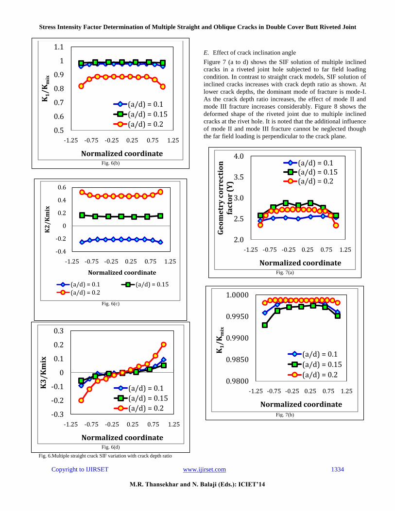
Fig. 6.Multiple straight crack SIF variation with crack depth ratio
E. Effect of crack inclination angle
Figure 7 (a to d) shows the SIF solution of multiple inclined
cracks in a riveted joint hole subjected to far field loading
condition. In contrast to straight crack models, SIF solution of
inclined cracks increases with crack depth ratio as shown. At
lower crack depths, the dominant mode of fracture is mode-I.
As the crack depth ratio increases, the effect of mode II and
mode III fracture increases considerably. Figure 8 shows the
deformed shape of the riveted joint due to multiple inclined
cracks at the rivet hole. It is noted that the additional influence
of mode II and mode III fracture cannot be neglected though
the far field loading is perpendicular to the crack plane.
Fig. 6(b)
0.5
0.6
0.7
0.8
0.9
1
1.1
-1.25 -0.75 -0.25 0.25 0.75 1.25
K1/
Km
ix
Normalized coordinate
(a/d) = 0.1
(a/d) = 0.15
(a/d) = 0.2
Fig. 6(c)
-0.4
-0.2
0
0.2
0.4
0.6
-1.25 -0.75 -0.25 0.25 0.75 1.25
K2
/K
mix
Normalized coordinate
(a/d) = 0.1 (a/d) = 0.15
(a/d) = 0.2
Fig. 6(d)
-0.3
-0.2
-0.1
0
0.1
0.2
0.3
-1.25 -0.75 -0.25 0.25 0.75 1.25
K3
/K
mix
Normalized coordinate
(a/d) = 0.1
(a/d) = 0.15
(a/d) = 0.2
Fig. 7(a)
2.0
2.5
3.0
3.5
4.0
-1.25 -0.75 -0.25 0.25 0.75 1.25
Ge
om
etr
y c
orr
ect
ion
fa
cto
r (Y
)
Normalized coordinate
(a/d) = 0.1(a/d) = 0.15(a/d) = 0.2
Fig. 7(b)
0.9800
0.9850
0.9900
0.9950
1.0000
-1.25 -0.75 -0.25 0.25 0.75 1.25
K1/
Km
ix
Normalized coordinate
(a/d) = 0.1
(a/d) = 0.15
(a/d) = 0.2

Stress Intensity Factor Determination of Multiple Straight and Oblique Cracks in Double Cover Butt Riveted Joint
Copyright to IJIRSET www.ijirset.com 1335
M.R. Thansekhar and N. Balaji (Eds.): ICIET’14
Fig. 7. Multiple inclined cracks SIF variation with crack depth ratio
F. Conclusion
SIF solution of multiple straight and inclined cracks in a
double cover butt joint has been determined numerically for
different crack depth ratios. Comparison of straight and
inclined crack SIF values reveals the following conclusions
1) As the crack depth ratio increases SIF solution of
straight cracks decreases considerably. The geometry
correction factor is high at the crack middle region
irrespective of the crack depth ratios considered in
the present work.
2) Significant variation in SIF solution of four and
double cracked model was observed which indicates
that number of cracks in a structure has an important
role on structural integrity assessment of structures.
3) The effect of mode II and mode III fracture increases
with inclined crack model compared with straight
cracked model. Thus one cannot neglect the effect of
mode II and mode III fracture even though the
loading is perpendicular to the crack plane.
REFERENCES
1) Roberto Galotolo, Karl-Fredrick, An experimental and numerical
analysis of residual strength of butt-joints panels with multiple site damage
2) Galip Kecelioglu, Stress and fracture analysis of riveted joints. A
thesis submitted to the graduate school of natural and applied sciences of MIDDLE EAST TECHNICAL UNIVERSITY
3) C. Calı`, R. Citarella, Residual strength assessment for a butt-joint
in MSD condition 4) Langrand.B, Deletombe.E, Markiewicz.E, Drazetic.P , 2001.
Riveted joint modeling for numerical analysis of airframe
crashworthiness. Finite Element Analysis Des. 38, 21-44.
5) Surendran M, Palani G. S, and Nagesh R. Iyer,Stress Intensity
Factors for Plates with Collinearand Non-Aligned Straight Cracks
Fig. 7(c)
-0.11
-0.1
-0.09
-0.08
-0.07
-0.06
-0.05
-0.04
-1.25 -0.75 -0.25 0.25 0.75 1.25
K2/
Km
ix
Normalized coordinate
(a/d) = 0.1
(a/d) = 0.15
(a/d) = 0.2
Fig. 7(d)
-0.06
-0.04
-0.02
0
0.02
0.04
0.06
-1.25 -0.75 -0.25 0.25 0.75 1.25
K3/
Km
ix
Normalized coordinate
(a/d) = 0.1
(a/d) = 0.15
(a/d) = 0.2
Fig. 8. Deformed riveted joint due to multiple inclined cracks