Embed Size (px)
Citation preview
OISD-STD-225
First Edition August 2007 Amended Edition October 2010
STORAGE, HANDLING AND DISPENSING AT
PETROLEUM RETAIL OUTLETS
PREPARED BY FUNCTIONAL COMMITTEE
OIL INDUSTRY SAFETY DIRECTORATE 7th FLOOR, NEW DELHI HOUSE
27, BARAKHAMBA ROAD, NEW DELHI-110001
<< Back Home Next >>
NOTE
OISD publications are prepared for use in the oil and gas industry under Ministry of Petroleum & Natural Gas. These are the property of Ministry of Petroleum & Natural Gas and shall not be reproduced or copied and loaned or exhibited to others without written consent from OISD. Though every effort has been made to assure the accuracy and reliability of the data contained in these documents, OISD hereby disclaims any liability or responsibility for loss or damage resulting from their use. These documents are intended to supplement rather than replace the prevailing statutory requirements.
FOREWORD
The Oil Industry in India is more than 100 years old. As such, a variety of practices have been in vogue because of collaboration/ association with different foreign companies and governments. Standardisation in design philosophies, operating and maintenance practices was hardly in existence at a national level in early days. This coupled with feed back from some serious accidents that occurred in oil & gas industry, the Ministry of Petroleum & Natural Gas in 1986 constituted a Safety Council assisted by the Oil Industry Safety Directorate (OISD) for formulating and implementing a series of self regulatory measures aimed at removing obsolescence, standardising and upgrading the existing standards to ensure standardisation and safer operations. Accordingly, OISD constituted a number of functional committees comprising of experts nominated from the industry to draw up standards and guidelines on various subjects.
Retail Outlets are the principal installations for refueling of MS/HSD for automotive use. The safety of these installations is of paramount concern keeping in view the associated hazards of petroleum products handled, vehicles and public. Accidents at Petroleum Retail Outlets in the recent past, emphasized the need for the industry to review the existing design, operation and maintenance practices in Petroleum Retail Outlets. Therefore, a need was felt to frame a standard for safe storage, handling of Petroleum Products at Retail Outlet. This document was prepared based on the accumulated experience and knowledge of industry members, and various national and international codes and practices. This document will be reviewed periodically for improvements based on the new experiences and better understanding. Suggestions may be addressed to :
The Coordinator, Committee on “Retail Outlet”
Oil Industry Safety Directorate, 7th floor, New Delhi House,
27, Barakhamba Road, New Delhi – 110001.
FUNCTIONAL COMMITTEE MEMBERS
NAME ORGANISATION LEADER Shri Ashoke Datta
IBP Co. Ltd., Mumbai
MEMBERS Shri R.C. Kaul
Petroleum & Explosives Safety Organisation, Nagpur.
Shri Vivek Srivastava, Reliance Industries Ltd., Mumbai Shri A.K. Goel Bharat Petroleum Corporation Ltd., Mumbai Shri Milind Pawar Shell India Marketing Ltd., Bangalore Shri R. Murali Hindustan Petroleum Corporation Ltd., Mumbai Shri M. Shailendra Indian Oil Corporation Ltd., Mumbai Shri V. Jagdish UL India Ltd. Bangalore Shri S.C. Gupta Oil Industry Safety Directorate, New Delhi MEMBER COORDINATOR Shri A. Mishra
Oil Industry Safety Directorate, New Delhi
CONTENTS
--------------------------------------------------------------------------------------------------------------------------------- S.NO. DESCRIPTION PAGE No. --------------------------------------------------------------------------------------------------------------------------------- 1.0 INTRODUCTION 2.0 SCOPE 3.0 DEFINITIONS 4.0 STATUTORY REQUIREMENTS 5.0 LAYOUT & FACILITIES 6.0 ELECTRICAL POWER DISTRIBUTION SYSTEM 7.0 OPERATING PROCEDURES 8.0 INSPECTION 9.0 MAINTENANCE 10.0 SAFETY EQUIPMENT 11.0 EMERGENCY PLAN AND PROCEDURE 12.0 TRAINING 13.0 CUSTOMER SAFETY & AWARENESS 14.0 REFERENCES ------------------------------------------------------------------------------------------------------------ ANNEXURES I Checklist for Daily Inspection II Checklist for Electrical Audit III Checklist for Safety Audit IV Format for Work Permit V Stock Receipt & Tanker Discharge Process
“STORAGE, HANDLING AND DISPENSING AT
PETROLEUM RETAIL OUTLETS” 1.0 INTRODUCTION
Motor Spirit (MS) / High Speed Diesel (HSD) are widely used as automotive fuels. There has been high growth in consumption of these products commensurate with the increase in number of vehicles. Accordingly, number of retail outlets for dispensing of MS/ HSD have gone up in the country. In recent times, petroleum retail outlets have witnessed addition of alternate fuels (namely LPG, CNG) and various other formats not connected to petroleum fuels. Accordingly, a need was felt to frame guidelines on safety of these Petroleum Retail Outlets as safety at these installations is one of the important considerations in view of the hazards associated with handling of these products, operating conditions such as pressure, storage of other flammable materials etc.
2.0 SCOPE
This standard lays down the minimum requirements in design, operation, inspection, maintenance, training, consumer safety at Petroleum Retail Outlets (PRO). It does not cover the certification or fitness requirements of vehicles using MS / HSD.
This Standard does not deal with provision of CNG and LPG dispensing facilities for automotive use in the same station which are covered in OISD-STD-179 and OISD-STD-210 respectively.
3.0 DEFINITIONS
Authorised Person : A person trained and assigned to carry out a specific job by the owner or marketing company.
Capacity : The maximum volume of water that can be stored in a
vessel/container at 15 oC at atmospheric pressure.
Competent Person : A person recognised by the concerned Statutory Authority for the purpose in respect of which the competency is required.
C-Store: C-Store means the area in which non-fuel goods / consumables are sold. Dispenser : The equipment provided in the retail outlet for delivering MS/ HSD to the Auto Fuel Tank of motor vehicles / approved receptacles. Emergency shut off : A shut off to cut off power supply as well as product supply which in an emergency, operates automatically or can be operated remotely. Fill Point : The point of inlet pipe connection of a bulk storage tank for MS/ HSD where hose is connected for filling the products into the tank. Vent Pipe : The pipe fitted on an underground tank in Petroleum Retail Outlets for breathing. Petroleum Retail Outlet : The area provided with facilities and specially designed for storage and dispensing to the fuel tanks of motor vehicles and any other approved receptacles. Pressure Vacuum Valve: A pressure and vacuum relief device used to limit the maximum pressure and vacuum that can exist in storage tank and vessel. Tank Truck / Tank Lorry / POL Tank Lorry: A truck mounted with a properly designed and approved tank for transportation of MS / HSD in bulk to the dispensing stations. Petroleum & Explosives Safety Organisation (PESO): The statutory body for licensing the retail outlet under Petroleum Rules, 2002.
4.0 STATUTORY REQUIREMENTS
Petroleum Retail Outlets are covered under Petroleum Rules, 2002 and require licence from PESO The site layout and construction of the retail outlet requires to be approved by PESO.
In addition to above, approval from other applicable Statutory Bodies and local authorities shall be obtained.
5.0 LAYOUT & FACILITIES
5.1 General
i. The space chosen for a petroleum retail outlet shall be sufficiently spacious to allow it to be designed to minimize the risk from the petroleum fuels to any person likely to be at or near the retail station.
ii. The layout should ensure unobstructed movement of all vehicles together
with adequate provision for entry and exit of Tank trucks.
iii. Location of the facilities, equipment , entrance, exit & paving shall be arranged in a such manner to avoid the risk of any collision amongst the motor vehicles.
iv. There should be unobstructed view of the operating and dispensing areas
from the salesroom.
v. Access for mobile fire fighting equipment to all the Retail Outlet facilities shall be ensured.
vi. The location of tanks, filling and vent pipes, dispensing equipment and
road tanker decanting area as well as on site buildings shall be designed to provide for satisfactory means of escape for persons in the event of fire or other incident.
vii. The hazardous areas shall be protected from sources of ignition.
viii. The items to be sold from a Convenience Store (C-Store) in a retail outlet
shall be decided keeping in view hazards associated with the items being stocked and sold. Open flame appliances shall not be used in PRO.
ix. Provision for car parking shall be made in PRO with C-Store @ one slot
distinctly marked for each 25 sq. metre of C- Store area.
x. Separate pathways outside dispensing area shall be provided for movement of customers for C-Store.
xi. Hazardous area classification shall be done in line with OISD-STD-113
and IS : 5571.
5.2 Storage Tanks
i. Petroleum shall be stored only in underground tanks in single / double walled [membrane] and its installation shall be outside any building.
ii. These shall be placed in an earthen or masonry or concrete pit and shall
be packed with sand/earth/gravel without leaving any space between the tank and concrete/masonry wall. Alternatively, tank shall be installed in earth pit in a manner that no part of the tank is less than 1.5 metre from any point of the marked boundary.
iii. No part of the space over the buried tanks shall be used for any purpose
other than installing equipment specifically meant for the withdrawal/ monitoring of contents of the tank.
5.2.1 Material of construction
Following materials shall be used for underground storage tanks.
Steel tanks : Carbon steel as per IS: 2062 or equivalent Design Code IS: 10987: 1992 for petroleum products or equivalent
GRP Tank : ASTM D4021, conforming to UL 1316 or equivalent,
5.2.2 Tank Installation
i. The underground tanks shall be either installed in the dedicated tank farm area “Away from Driveway (Remote Tank Farm)” or under the driveway with an appropriate reinforced concrete slab above the tank (“Under Driveway”).
ii. All tanks shall be pneumatic or hydro tested as per the design code or
operating pressure, whichever is higher, before boxing up of the tanks.
iii. Steel tanks shall be suitably protected against corrosion.
iv. Design shall provide adequate protection against buoyancy for the Tanks installed.
v. Installation of GRP / ERP tanks shall follow the manufacturer’s
recommendations.
5.2.2.1 Tanks installed under driveway
i. Underground tanks shall be installed under concrete slab or alternate pavement material. Design consideration shall take care of loading either through masonry pit walls or back fill material and burying depth of tanks.
ii. Man way covers (metallic / GRP) shall be designed for the intended
vehicle load and to prevent water ingress during rain and also ensure safety of tank fittings.
iii. RCC slab for the tank pit to be designed for the intended vehicle load.
5.2.2.2 Tanks installed away from driveway
i. Underground tanks preferably to be installed in a masonry pit to ensure product retention within the pit in the event of any leakage or overflow.
ii. Installation of GRP / FRP tanks shall follow the manufacturer's recommendation.
iii. Man ways sump shall be covered adequately in order to avoid ingress of rain water and also to ensure safety of tank fittings.
5.3 Fill points
i. The fill points for the tank/tanks, whether off set or direct fill shall be
located in such a manner so that any spillage of petroleum and its subsequent ignition does not pose any immediate threat to members of the public or fore court or delivery staff.
ii. Fill points shall be located in the open air such that any flammable concentrations of vapours resulting from normal filling operations or spillage does not reach potentially ignition sources, or accumulates in either building or out door locations so as to pose a danger.
iii. The fill points shall maintain a minimum safety distance of 3 mtrs. all round including property boundary or any other structure where a source of ignition is likely to be present. This distance of 3 m may be reduced if a fire – resistant wall is constructed, e.g. of brick or concrete, which is at least 2 m high and extends sideway or parallel to the boundary. If the wall is a part of a building which houses a sensitive population, such as a school, hospital or residential dwelling, this distance should be increased to 12 m.
iv. Fill pipes shall have minimum 1:200 slope towards the storage tank to ensure easy flow due to gravity and also to avoid any product retention with in the fill pipe.
v. Fill pipe shall be carried down nearly to the bottom of the tank to prevent fire hazard due to generation of static charge arising out of free fall of product.
vi. Proper identification of fill points for various types of fuels shall be provided to avoid wrong decantation.
vii. An “earthing bus” shall be provided in the close vicinity of fill points. viii. Hose connections shall be properly tightened using screwed / cam lock
couplings. ix. Fill pipe caps shall be made of softer material like brass or aluminium. x. Fill cap shall have a proper locking system and key shall be kept under the
custody of the authorized person. xi. Fill points shall be so located that the tank lorry when under decantation is
in drive out position.
5.4 Pipelines
i. Pipelines from tanks to dispensing points and vent pipes shall be routed below the ground surface. It shall not be under a building or other features which prevent access to the pipelines after installation. Fuel Pipes should be sloped towards Underground Storage Tank.
ii. In case of pressurised system, entire piping system including the appurtenances shall wherever possible be constructed with welded joints and where necessary with flanged joints. The number of flanged joints shall be kept down to a minimum.
iii. Piping shall run as directly as practical from one point to another and with as few restrictions such as elbows and bends as conditions will permit.
iv. Provision shall be made in the piping including connection to the bulk storage vessel to compensate for expansion, contraction, jarring and vibration
v. Each pipe line shall be hydro tested as per design code. Alternatively, it shall be hydro tested at 1.5 times the design pressure maintaining at least for a period of 30 minutes.
vi. Pipe lines shall be earthed and to maintain electrical continuity suitable “Jumpers” to be provided at the flanged joints to ensure dissipation of static charge developed due to product flow in pipe line. The resistance value between each joint shall not exceed 1 ohm.
vii. The pipelines shall be protected against corrosion by suitable coating strapping and where necessary by cathodic protection.
5.4.1 Material of Construction or equivalent (being finalized)
i. Material specifications for metallic piping & fittings shall conform to IS-1978 or equivalent.
ii. Material specifications for non metallic piping and fittings shall conform to
UL 971, EN 14125 or equivalent.
5.5 Vent pipes
i. Each tank shall be provided with independent vent pipe(s) of adequate
capacity unless vapour recovery system is installed. ii. Vent point shall never be located under any shade /cover. iii. Open ended vent pipes shall extend to a height greater than the maximum
liquid level of a road tanker likely to deliver petroleum to the underground tanks and shall not be less than 4 mtrs. In case of venting above the canopy, the vent pipes shall be terminated 1.5 mtrs above it.
iv. The vent pipe opening shall also observe minimum 4 mtr. clearance in the horizontal plane from all structures.
v. The vent pipe shall be protected against damage by inadvertent collision with vehicles.
vi. The outlet (opening) of the vent pipe shall be covered with two layers of non corrosive metal wire mesh having not less than 11 meshes per square centimeter and a rain cap or bend downwards.
vii. Vent pipe shall be gradually sloped towards the tank to avoid chocking of vent pipe due to any water ingress or due to product in the event of tank overflow.
viii. The vertical portion of the vent pipe shall not be provided with any intermediate thread joint.
5.6 Dispensing equipment
i. Dispensers shall be located In the open space where they will be adequately ventilated.
ii. The dispensers shall maintain a minimum distance of 6 mtrs. from any above-ground structure / property boundary.
iii. The dispenser shall be installed on a firm foundation and protected against physical damage from vehicles.
iv. A shear valve to be provided in dispensers in a pressurised system. v. The length of the hose connected to the dispenser shall be kept minimum
keeping in view the operational requirement and shall not in any case exceed 4 m.
vi. Breakaway coupling shall be installed in Dispensing Hose / nozzle,
vii. The dispensing hose shall be electrically and mechanically continuous and earthed. Necessary provisions shall be available in Dispenser to earth the receptacles other than fuel tank of vehicles while dispensing.
viii. Installation of any Electronic Peripheral device shall be done at a 1200mm above the base level of the dispensing unit.
5.7 Decantation locations
i. The road tanker delivery locations for unloading into storage tanks shall be in the open, away from the sales building, dispensing activities and emergency escape routes.
ii. The hose used shall conform to OISD-STD-135. iii. Hose length shall not be more than 5.5 m. iv. The location chosen shall allow the road tanker to gain access without the
need to reverse on to the site. v. The discharge area also needs to be substantially leveled but should also
incorporate drainage arrangements to intercept largest possible likely spillage.
5.8 Sales room
i. Any building or room intended to serve as a control point for a retail outlet shall preferably be so located that an attendant in the sales room can see the forecourt and the dispensing area clearly.
5.9 Canopy
i. The canopy, if provided, for weather protection shall not adversely effect the ventilation or access to the equipment.
ii. Canopy heights installed at fuel fore court shall have at least 300mm clearance from the maximum permitted height recommended by Central Motor Vehicle Rules for the vehicles to be fuelled.
iii. Wind and seismic load for the canopy design shall be considered as per IS: 875 and IS:1893 respectively.
iv. Canopy structure shall be properly earthed as per IS :3043.
6.0 Electrical Power Distribution System
The following elements / components shall be considered in designing the Electrical Power Distribution system in a Retail Outlet.
• Total electrical load for the entire Retail Outlet • Availability, Suitability & Reliability of the State Electricity Board (SEB)
grid. • Fault (KA) rating of the SEB Feeder • Load to be fed from back-up DG power • Load which need stabilized and/or Uninterrupted Power Supply (UPS)
supply to function smoothly • Rated load of the connected & future equipment The list of reference Standards / Codes is covered under Chapter 14. For downstream distribution on the LT side, a suitable LT Power Distribution Panel (PDP) shall be designed to feed the various types of loads in PRO safely from a centralized location.
6.1 Elements of Protection
a. Protection shall be provided to guard against sudden failures viz. neutral disconnection and against overload, short-circuit & earth fault.
b. The motors shall be protected against short circuit and overload. c. Protection shall be provided for variation in voltage, frequency and phase
unbalance.
6.2 Backup Power Supply
The following shall be considered to arrive at the capacity of the Diesel Generator (DG) set, if provided.
• “Critical” lighting fixtures are fed with DG supply. • The DG rating shall be sufficient enough to sustain the starting power
requirements of the connected motors without disturbing normal operation of the other loads.
6.2.1 The Retail Outlet operating after sunset, emergency lighting with battery
backup shall be provided near the DG set, dispenser, sales room and electrical room.
6.3 Layout & Installation
i. For HT supply, the substation shall mainly consist of lightning arrestor, HT fuse, transformer, SEB metering cubicle.
(a) Retail Outlets with an outdoor type of HT/LT substation, a DP
structure surrounded with barbed wire fence, entry gate shall be provided outside the licensed area. Alternatively, a Packaged Sub Station shall be provided.
ii. The Power Distribution Panel, Automatic Voltage Stabiliser, UPS shall
be installed with following clear spaces for ease of safe operation & maintenance activities:
In front of the equipment - 1000 mm. Behind the equipment - > 750 mm. (if approach is required)
- < 200 mm (if approach is not required) At sides - > 750 mm. Between equipments
- < 200 mm. (if approach is not required)
iii. Electrical room shall be provided with proper ventilation to extract the heat generated in the power distribution equipments.
iv. All electrical equipment shall be as per IS : 5572 in line hazardous area
classification.
v. Cable entry shall be through gland plate either at top or bottom. Further spare holes, if any, in the gland plates shall be blocked.
vi. Cables shall be neatly dressed, clamped and tag marked to easily
identify the feeder and device it connects.
vii. The cable entry holes on the building wall in cable trench or overhead shall be sealed to prevent entry of water.
viii. For underground laying under different conditions of terrain the methods
may be as follows:-
(a) For direct burial within PRO, top of the topmost layer of cable shall be laid at a minimum depth 600 mm from surface of ground, each subsequent layer at the bottom shall maintain a minimum vertical clearance of 150 mm.
(b) For road crossings, cables shall be routed at a minimum depth of
600mm from surface and thru’ pipe. The pipe may be of GI or steel reinforced hume pipe or HDPE pipe.
6.4 Earthing System
The earthing system shall be designed as per IS 3043 and following procedures shall be followed:-
i. All metallic structure, pipe fittings and enclosures of electrical
equipments shall be connected to earth.
ii. Equipment rated up to 230 V, 1-phase supply, the enclosure shall be grounded at least one point.
iii. Equipment rated above 400 V, 3-phase supply, the enclosure shall
be grounded at least at two separate points.
iv. Two nos. earth pits shall be provided for each of transformer / DG set neutral earthing, equipment earthing.
v. All earthing pits except DG neutral and instrument / IT earthing
shall be connected through grid (s).
vi. In lightning prone areas, a risk assessment shall be carried out for need of lightning protection and guidelines given in IS 2309 shall be followed.
6.5 Emergency Stop System
i. Emergency stop system shall be provided to cut off the power supply to all metering pumps/ dispensing equipment and associated equipment, other than certified intrinsically safe equipment at PDP and in / on Sales Building. On actuating any of these push buttons, electrical power supply to entire PRO shall be isolated instantaneously.
ii. The push button shall be of red colour, mushroom type, marked and a key
to open. 6.6 Illumination System
Following Minimum illumination level (lux) shall be maintained in various areas of the PRO for safety and visibility.
Area LUX Approach Area Under the canopy Customer Care Room Electrical Room
50 150 100
100
The design shall ensure that illumination is glare-free for customers driving in vehicle in a Retail outlet.
7.0 OPERATING PROCEDURES
7.1 General
i. Operating personnel of retail outlet shall possess adequate knowledge and experience of handling MS/ HSD to ensure functioning of the station in a safe and efficient manner.
ii. During unloading of the product from the tank truck to the bulk storage
vessels, the tank truck shall be parked in the space marked for the purpose.
iii. Operation of dispensing fuel to motor vehicles shall be suspended during
the period of unloading of fuel from tank truck to the storage tanks.
iv. All operations at Retail Outlet shall be suspended during the period of evacuation of the storage tank for maintenance and testing.
v. MS/ HSD shall not be filled in the fuel tank of motor vehicle while the
engine of the vehicle is running.
vi. The operating procedures shall be displayed at relevant locations for the unloading of tank truck.
vii. Dos and Don’ts shall be prominently displayed in Retail Outlet. (Please
refer item no. 13)
viii. Action in the event of emergency shall be clearly established and understood by all concerned and displayed prominently.
ix. The following are the critical activities ;
a. Decantation b. Management of the Forecourt / Fuelling area c. Sampling
7.2 Decantation of Tank Lorries
On receipt of Tank lorry from the supply point, Dealer or his authorized representatives shall check seals, match the numbers with the supply point documents, number of compartments and quantity/ product contained therein. The unloading operations shall be done in presence of the authorised person at Retail Outlet & Tank Truck Crew. The procedure for stock receipt and tank lorry discharge is given in annexure – V.
After decanting the product into the tank, at least 50 liters of product should be dispensed through the pump before taking sample from the pump nozzle for ascertaining the density of the product in the storage tank after receipt. The density at 150C thus ascertained should be recorded in the density register.
7.3 Forecourt Management
i. Guide the vehicle to the position at the designated area of the retail outlet facing the direction of exit.
ii. Do not leave the vehicle unattended during refueling operation.
iii. Ensure that sources of ignition, such as pilot lights, electrical ignition
devices, electrical appliances/ gadgets, and engines located on the vehicle being refueled are turned off before dispensing of fuel to a vehicle.
iv. Delivery Sales Person must show zero setting to the motorist before
commencing delivery.
v. Deliver product to customer as required .
vi. After completion of delivery, remove nozzle and place it on the Pump boot.
vii. Position the next vehicle and repeat all steps as above.
viii. At the end of the day’s work, ensure that valves are closed, hoses are properly stowed and electrical equipment is switched off.
ix. Always guide all vehicles entering into the retail outlets to designated area
for refueling.
x. Important operational activities shall be logged and records of such activities highlighting receipt, inventory, level, pressure, temperature, equipment running etc shall be maintained.
xi. A two-wheeler shall be re-fueled only after the Riders have dismounted.
7.4 Sampling
i. The samples shall be taken in approved containers duly earthed/ bonded in line with the industry guidelines.
ii. The samples shall be stored at designated approved place.
iii. Total storage of samples shall not exceed 30 litre for Class A product.
iv. The samples shall not be poured back directly to the storage tank.
v. The samples shall be collected in a separate receptacle for each product
and transfer to storage tank through a container fitted with hose. The retail outlet operations shall be suspended during this transfer.
8.0 INSPECTION
i. A well designed system of periodic inspection of all facilities of retail outlet shall be formulated to maintain it in safe operable condition all the time.
ii. Safety audit of the retail outlet shall be undertaken & certificate of fitness
declaring integrity with respect to equipment, facilities, operations & safety procedures shall be accordingly issued. Check list for inspection is enclosed as Annexure -III.
iii. All recommendations of the safety audit/ inspections shall be complied in a
time bound manner and records maintained thereof.
iv. The system of permit to work shall be established for non-routine works with and such works shall be undertaken with full knowledge and approval by authorised person.
v. Equipment appurtenances, protection devices associated with the
dispensing unit as incorporated in the design and approved by PESO shall be tested, maintained, repaired and replaced as recommended by the manufacturer.
vi. Checklist shall cover conformity with the design intention, operating and
maintenance procedures, preventive measure & protection systems and safety practices.
vii. The earthing resistance shall be checked at least once a year and records
maintained thereof.
8.1 SAFETY INSPECTIONS / AUDIT
The safety inspections / audit of Petroleum Retail Outlet shall be carried out as given below:
TYPE FREQUENCY AGENCY
Safety Inspection Daily Operating personnel
Safety Audit Once in 6 months Company authorised Person / Agency
Electrical Audit Once a year Company authorised Person / Agency
The typical checklist for these inspections/ audits are enclosed as Annexure-I, Annexure-II and Annexure-III which shall be used as a guideline to develop comprehensive checklists to check compliance and also proper system to liquidate the non complied points with target dates.
9.0 MAINTENANCE
9.1 GENERAL
i. A comprehensive maintenance system of all facilities of retail outlet shall
be formulated to maintain it in safe operable condition all the time.
ii. Preventive maintenance schedules shall be drawn for all equipment in accordance with manufacturer’s recommendations and established mandatory / recommendatory standards. Records of all preventive maintenance undertaken shall be maintained and updated from time-to-time.
iii. All repairs, non routine maintenance work shall be carried out after
issuance of work permit as per the procedure and format enclosed as annexure - IV. The format need to filled in duplicate.
iv. The work permit shall be issued by company authorized person or dealer
or manager at the retail outlet as per the class of activities detailed in item (v) & (vi) given below.
v. The following typical activities involving maintenance of Operational area & office requires work permits which can be issued by dealer/ manager at the retail outlet or company authorized person. The dealer/company authorized person will issue the permit to contractor or his authorized person for carrying out the assigned work after ensuring compliance with laid down conditions.
a. All activities capable of producing a spark inside a hazardous area. b. Access into a building / canopy roof. c. Access into a building canopy cavity. d. Concrete cutting in the hazardous zone. e. Electrical switch Board work. f. Excavation including Forecourts. g. Forecourt surface repair. h. Water Removal from Under Ground Tank. i. Operation of all electrical and electronic instruments inside hazardous
areas, unless certified intrinsically safe. j. Promotional activities on forecourts. k. Signage, including canopy signage / lighting not covered by long term,
routine maintenance contract. l. Setting up of temporary equipment including product recovery
equipment. E.g. Compressor, water blasting equipment etc.
vi. The following needs work permits which shall be issued by company authorized person. The company representative or authorised person will issue the permit to dealer or his representative who in turn will issue the same to contractor for carrying out the assigned work after ensuring compliance with laid down conditions
a. Repair / rework / cleaning on the tanks and pipelinework b. Tank Removal / Decommissioning. c. Non-routine maintenance / replacement / major electrical work within
hazardous area. d. Oxygen Deficiency / Inert gas Entry. e. Pneumatic / Hydrostatic pressure testing. f. Oil interceptor cleaning – where entry into the interceptor is required. g. Hot work including but not limited to welding / grinding / gas cutting. h. Demolition / revamping.
10.0 SAFETY EQUIPMENT
i. Each dispensing unit shall be covered by at least 2 nos. ISI marked 10 kg
DCP Fire Extinguishers placed at a safe location within 3m radius. ii. Minimum 1 no. 4.5 kg CO2 fire extinguisher conforming to IS :2878 shall
be available in each electrical meter room.
iii. Minimum 4 nos. sand buckets filled with dry sand should be available at the premises.
iv. All employees working in the premises must be conversant with the safe handling of petroleum products and first hand knowledge of the fire fighting & emergency handling.
v. Insulated pliers, screw driver, non-sparking tools , flameproof torch shall be available in the premises.
vi. All periodic tests shall be carried out by competent / authorised persons, as applicable and records shall be maintained.
vii. Fire extinguishers are to be periodically tested and maintained as per OISD-STD-142.
viii. The fire extinguishers are to be checked as per the following schedule:
• Visual check of the extinguisher : Daily • Condition of DCP, Hose, Nozzle and safety clip : Every month • Weight checking of CO2 Cartridge : Every Quarter • Performance Testing & DCP Extinguisher : Every Year • Pressure Testing of Extinguisher : Every Three years
11.0 EMERGENCY PLAN AND PROCEDURE i. Each Retail Outlet shall be provided with at least 2 points for emergency
shutdown. ii. The Operating Company having control over the Retail Outlet shall draw
an operational emergency plan keeping in view the following:
a) Major failure of fittings resulting in spillage b) Accidents or other emergencies, which can affect the Retail
outlet c) Electrical Emergencies d) Civil emergencies e) Any other risk arising from the existence or operation of the
Retail Outlet
The above emergency plan shall be disseminated amongst all personnel involved and ensured that they understand their roles and responsibilities in the event of an emergency.
iii. The in-charge of the Retail Outlet shall maintain close liaison with Fire
Service, Police, District Authorities and marketing company.
iv. Important telephone numbers for emergency use shall be displayed prominently in the Retail Outlet.
v. Means of communication shall be always at the disposal of the In charge
of the Retail Outlet. vi. Emergency Action Plan should be tested with mock drill at least once a
year. vii. First Aid Kit shall contain items to handle possible emergencies as per
State Factories Rules. viii. Shock treatment chart written in bilingual & local languages. RO
attendants shall be given training on how to treat an electrocuted person before help from a doctor is available.
12.0 TRAINING
The objective of training is to provide good understanding of all the facets of operations at the Retail Outlet. Training shall ensure that the jobs are performed in accordance with the laid down procedures and practices.
i. Each oil company shall develop training module of their own which should
include inter-alia of the following :
a) Hazardous characteristics of product handled. b) Familiarisation with operational procedures & practices. c) Hands on experience on operation of equipment. d) Knowledge of emergency and manual shut down systems e) Immediate and effective isolation of any spill f) Safety features and accident prevention. g) Fire fighting facilities, its upkeep and operation. h) Evacuation and safe egress of the vehicles in an emergency. i) Housekeeping j) Decantation k) First aid l) Dos & Don’ts m) Emergency plan./drills
Additionally, people shall be trained for specific job / activity.
ii. Proper records for the training and refresher courses shall be maintained.
13.0 CUSTOMER SAFETY & AWARENESS
13.1 Display of important information : At Retail Outlet, the particulars of licence, emergency telephone nos. of local fire service, police, marketing company and emergency instructions shall be conspicuously displayed.
i. Caution boards shall be displayed near the dispenser for customer awareness as below :
a. Stop the engine before refueling b. No smoking c. Non-use of Mobile phone
13.2 DOs & DON’Ts DOs i. Switch off the mobile phone. ii. Switch off the engine before commencement of refueling . iii. Ensure a 10 kg DCP Fire Extinguisher is available near the Dispenser.
iv. In case of any spill / fire observed, press the “EMERGENCY STOP ”
button on the Dispenser. DON’Ts i. Do not start the engine / drive away the vehicle till the filling nozzle has
been disconnected from the filler cap of the vehicle. ii. Do not refuel the vehicle during the period MS/HSD is being decanted
the tank. iii. Do not Smoke
iv. Do not use naked flame
14 REFERENCES ix. Petroleum Rules – 2002 x. Marketing Discipline Guidelines xi. IS 2062 :1999 : Steel for General Structural Purpose
xii. IS 1239 : Part 1 : 2004, and IS 1239 : Part 2 : 1992, Steel Tubes and Other Wrought Steel Fittings.
xiii. IS-5572 : Hazardous Area Classification xiv. IS 10987 : 1992 : Code of Practice for Design, Fabrication, Testing and
Installation of Underground / Above ground Horizontal Cylindrical Storage Tanks for Petroleum Products.
xv. IS 2309 : 1989 : Code of Practice for the Protection of Building and Allied Structures Against Lighting
xvi. IS 3043 : 1987 : Code of Practice for Earthing xvii. UL 1316 : Glass-Fiber-Reinforced Plastic Underground Storage Tanks for
Petroleum Products, Alcohols, and Alcohol-Gasoline Mixtures. xviii. UL 971 : Nonmetallic Underground Piping for Flammable Liquids xix. EN 14125 : 2004 : Thermoplastic and Flexible Metal Pipe Work for
Underground Installation at Petrol Filling Station xx. OISD-STD-113: Classification of Area for electrical installations at
Hydrocarbon processing and handling facilities xxi. OISD-STD-142: Inspection of fire fighting equipments and systems xxii. OISD-STD-135: Inspection of loading and unloading hoses for petroleum
products xxiii. IS-1978 : Indian Standard Specification for Line Pipe (Second Revision) xxiv. UL 87- Power Operated Dispensing Device for Petroleum Product or
Relevant Standards xxv. UL 79- Power Operated Pumps for Petroleum Dispensing Products or
Relevant Standards
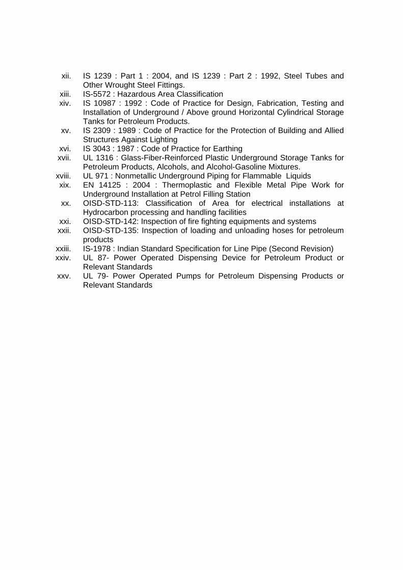
Annexure - I
Daily Check List Date: Time: Sr.No Particulars Remarks (To be carried out by individual DSM on rotational basis) 1. All the Dispensing Units externally & internally clean. In the sand below
Dispensing units there is no Spillage of product and inflammable waste. Y/N
2. All the piping connections of Dispensing units & tank farm are leak free & there is no sweating in the joints
Y/N
3 Wire mesh in the product vent is not choked with foreign matter. Y/N 4. Fire Extinguishers are in place and are valid for use as on date. Y/N 5. Road & pathways are clear of any obstructions. Y/N 6 Safety signs are in place. (No smoking, Mobile Phone Switch Off) Y/N 7 Tank farm is clean and free of dry vegetation. Y/N 8 The sand in the fire bucket is dry and without any lumps. Y/N 9 All the light fixtures at the periphery, canopy and the sales room are in
working condition. Y/N
10 No employee of the Retail Outlet is in an intoxicated state Y/N 11 Daily briefing [Dos and Don’ts] on Safety before starting of shift has
been carried out Y/N
12 General House Keeping is good.
Y/N
13 There are no electrical faults observed in the entire Retail Outlet. Y/N 14 Any other unsafe condition Y/N
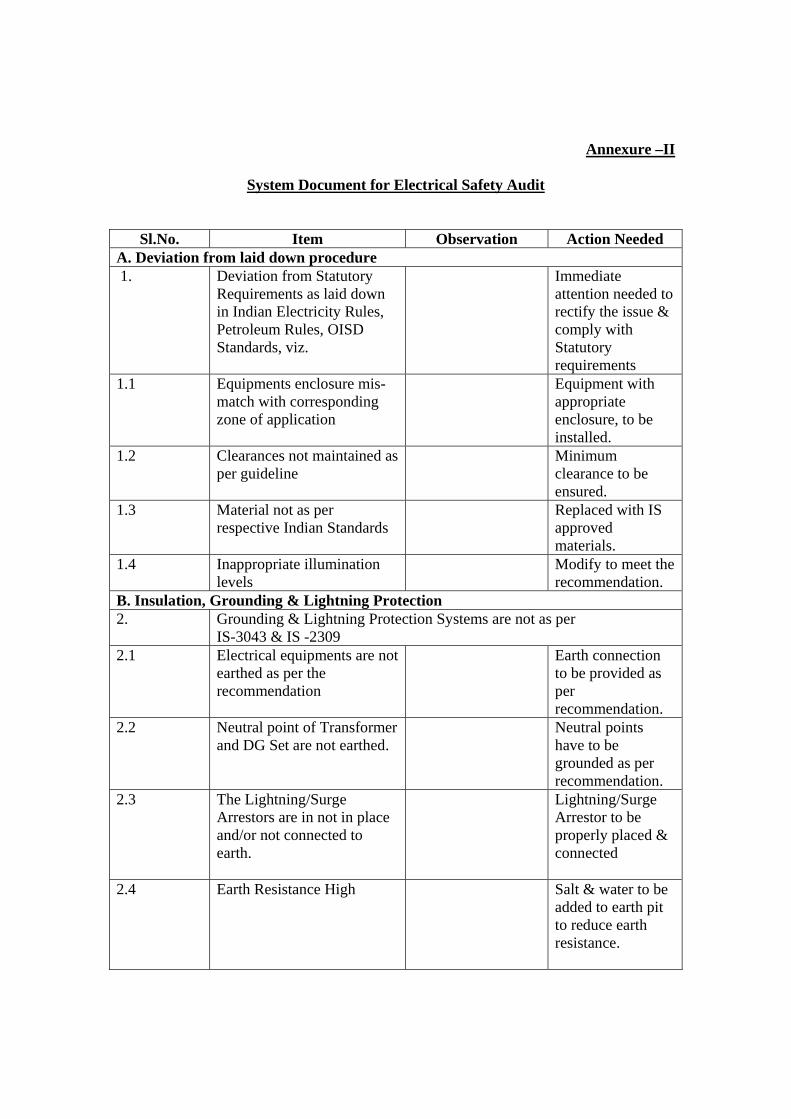
Annexure –II
System Document for Electrical Safety Audit
Sl.No. Item Observation Action Needed
A. Deviation from laid down procedure 1. Deviation from Statutory
Requirements as laid down in Indian Electricity Rules, Petroleum Rules, OISD Standards, viz.
Immediate attention needed to rectify the issue & comply with Statutory requirements
1.1 Equipments enclosure mis-match with corresponding zone of application
Equipment with appropriate enclosure, to be installed.
1.2 Clearances not maintained as per guideline
Minimum clearance to be ensured.
1.3 Material not as per respective Indian Standards
Replaced with IS approved materials.
1.4 Inappropriate illumination levels
Modify to meet the recommendation.
B. Insulation, Grounding & Lightning Protection 2. Grounding & Lightning Protection Systems are not as per
IS-3043 & IS -2309 2.1 Electrical equipments are not
earthed as per the recommendation
Earth connection to be provided as per recommendation.
2.2 Neutral point of Transformer and DG Set are not earthed.
Neutral points have to be grounded as per recommendation.
2.3 The Lightning/Surge Arrestors are in not in place and/or not connected to earth.
Lightning/Surge Arrestor to be properly placed & connected
2.4 Earth Resistance High
Salt & water to be added to earth pit to reduce earth resistance.
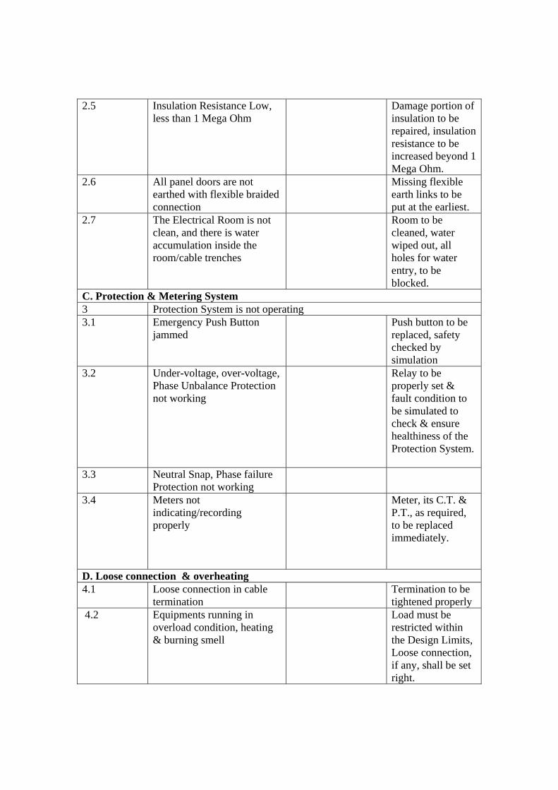
2.5 Insulation Resistance Low, less than 1 Mega Ohm
Damage portion of insulation to be repaired, insulation resistance to be increased beyond 1 Mega Ohm.
2.6 All panel doors are not earthed with flexible braided connection
Missing flexible earth links to be put at the earliest.
2.7 The Electrical Room is not clean, and there is water accumulation inside the room/cable trenches
Room to be cleaned, water wiped out, all holes for water entry, to be blocked.
C. Protection & Metering System 3 Protection System is not operating 3.1 Emergency Push Button
jammed Push button to be
replaced, safety checked by simulation
3.2 Under-voltage, over-voltage, Phase Unbalance Protection not working
Relay to be properly set & fault condition to be simulated to check & ensure healthiness of the Protection System.
3.3 Neutral Snap, Phase failure Protection not working
3.4 Meters not indicating/recording properly
Meter, its C.T. & P.T., as required, to be replaced immediately.
D. Loose connection & overheating 4.1 Loose connection in cable
termination Termination to be
tightened properly 4.2 Equipments running in
overload condition, heating & burning smell
Load must be restricted within the Design Limits, Loose connection, if any, shall be set right.
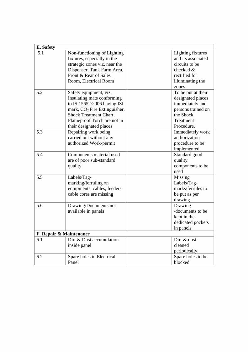
E. Safety 5.1 Non-functioning of Lighting
fixtures, especially in the strategic zones viz. near the Dispenser, Tank Farm Area, Front & Rear of Sales Room, Electrical Room
Lighting fixtures and its associated circuits to be checked & rectified for illuminating the zones.
5.2 Safety equipment, viz. Insulating mats conforming to IS:15652:2006 having ISI mark, CO2 Fire Extinguisher, Shock Treatment Chart, Flameproof Torch are not in their designated places
To be put at their designated places immediately and persons trained on the Shock Treatment Procedure.
5.3 Repairing work being carried out without any authorized Work-permit
Immediately work authorization procedure to be implemented
5.4 Components material used are of poor sub-standard quality
Standard good quality components to be used
5.5 Labels/Tag-marking/ferruling on equipments, cables, feeders, cable cores are missing
Missing Labels/Tag-marks/ferrules to be put as per drawing.
5.6 Drawing/Documents not available in panels
Drawing /documents to be kept in the dedicated pockets in panels
F. Repair & Maintenance 6.1 Dirt & Dust accumulation
inside panel Dirt & dust
cleaned periodically.
6.2 Spare holes in Electrical Panel
Spare holes to be blocked.
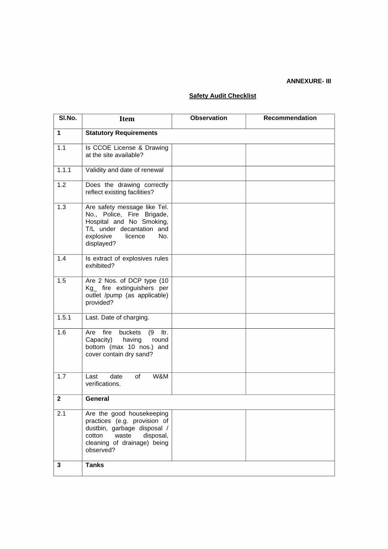
ANNEXURE- III
Safety Audit Checklist
Sl.No. Item Observation
Recommendation
1 Statutory Requirements
1.1 Is CCOE License & Drawing at the site available?
1.1.1 Validity and date of renewal
1.2 Does the drawing correctly reflect existing facilities?
1.3 Are safety message like Tel. No., Police, Fire Brigade, Hospital and No Smoking, T/L under decantation and explosive licence No. displayed?
1.4 Is extract of explosives rules exhibited?
1.5 Are 2 Nos. of DCP type (10 Kg_ fire extinguishers per outlet /pump (as applicable) provided?
1.5.1 Last. Date of charging.
1.6 Are fire buckets (9 ltr. Capacity) having round bottom (max 10 nos.) and cover contain dry sand?
1.7 Last date of W&M verifications.
2 General
2.1 Are the good housekeeping practices (e.g. provision of dustbin, garbage disposal / cotton waste disposal, cleaning of drainage) being observed?
3 Tanks
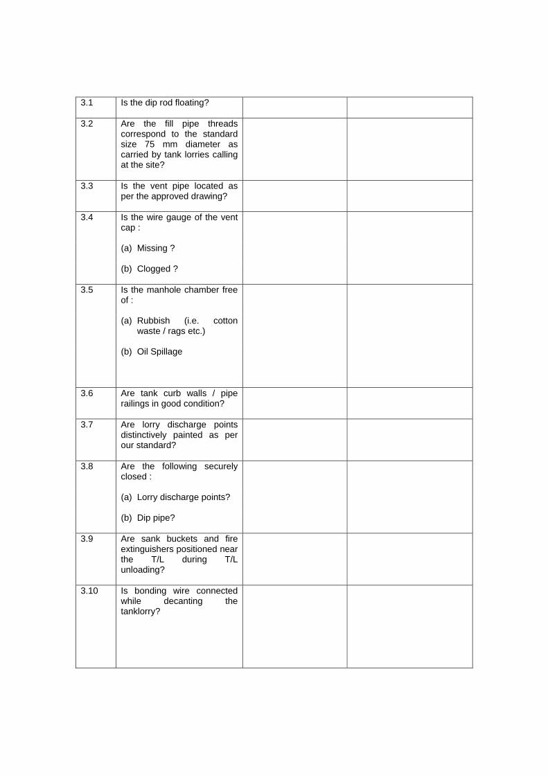
3.1 Is the dip rod floating?
3.2 Are the fill pipe threads correspond to the standard size 75 mm diameter as carried by tank lorries calling at the site?
3.3 Is the vent pipe located as per the approved drawing?
3.4 Is the wire gauge of the vent cap :
(a) Missing ?
(b) Clogged ?
3.5 Is the manhole chamber free of :
(a) Rubbish (i.e. cotton waste / rags etc.)
(b) Oil Spillage
3.6 Are tank curb walls / pipe railings in good condition?
3.7 Are lorry discharge points distinctively painted as per our standard?
3.8 Are the following securely closed :
(a) Lorry discharge points?
(b) Dip pipe?
3.9 Are sank buckets and fire extinguishers positioned near the T/L during T/L unloading?
3.10 Is bonding wire connected while decanting the tanklorry?
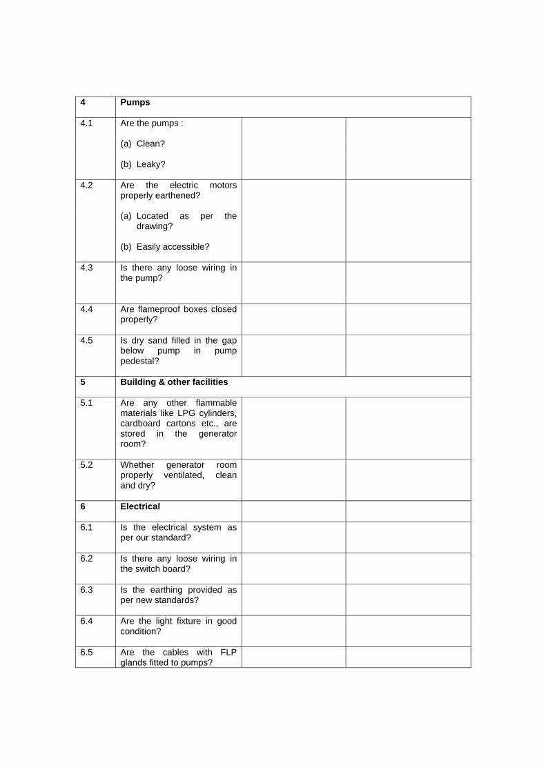
4 Pumps
4.1 Are the pumps :
(a) Clean?
(b) Leaky?
4.2 Are the electric motors properly earthened?
(a) Located as per the drawing?
(b) Easily accessible?
4.3 Is there any loose wiring in the pump?
4.4 Are flameproof boxes closed properly?
4.5 Is dry sand filled in the gap below pump in pump pedestal?
5 Building & other facilities
5.1 Are any other flammable materials like LPG cylinders, cardboard cartons etc., are stored in the generator room?
5.2 Whether generator room properly ventilated, clean and dry?
6 Electrical
6.1 Is the electrical system as per our standard?
6.2 Is there any loose wiring in the switch board?
6.3 Is the earthing provided as per new standards?
6.4 Are the light fixture in good condition?
6.5 Are the cables with FLP glands fitted to pumps?
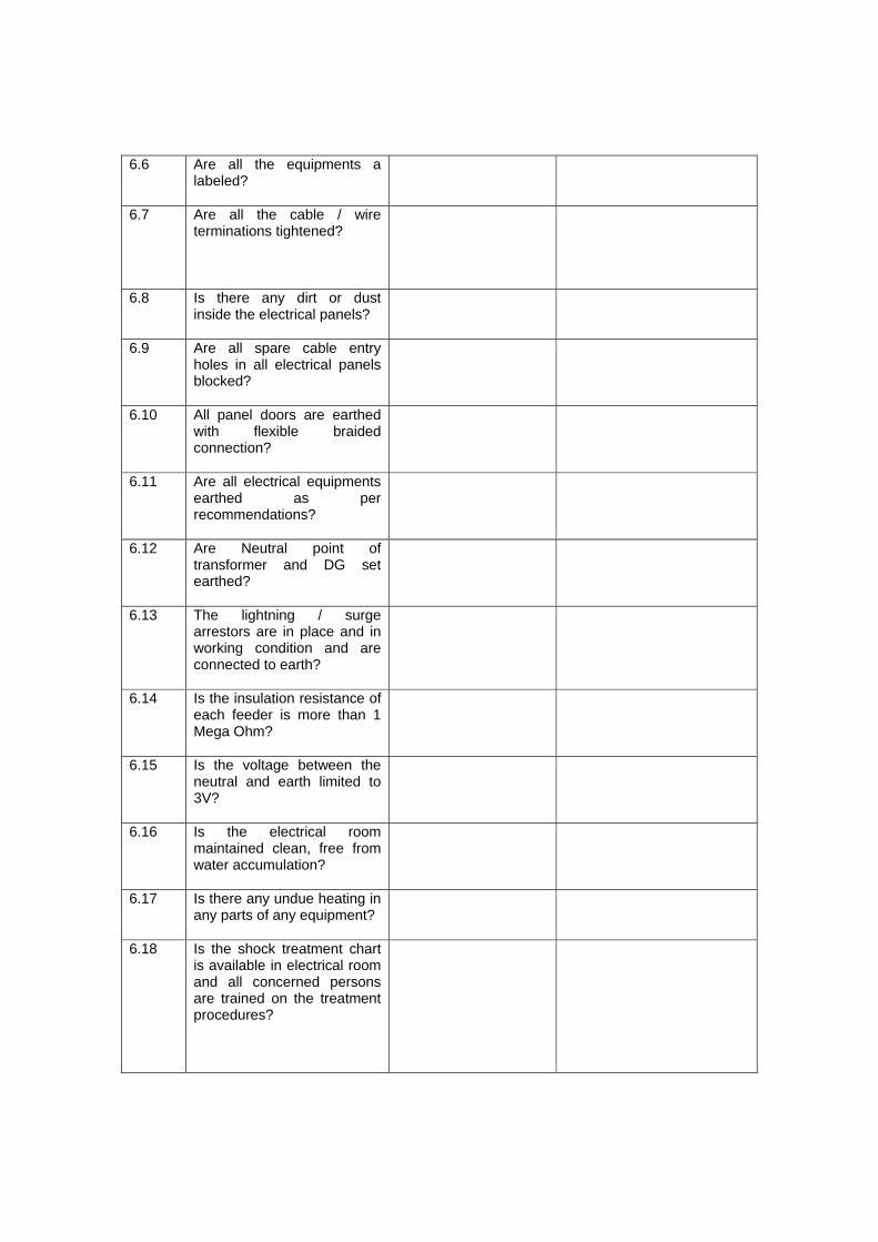
6.6 Are all the equipments a labeled?
6.7 Are all the cable / wire terminations tightened?
6.8 Is there any dirt or dust inside the electrical panels?
6.9 Are all spare cable entry holes in all electrical panels blocked?
6.10 All panel doors are earthed with flexible braided connection?
6.11 Are all electrical equipments earthed as per recommendations?
6.12 Are Neutral point of transformer and DG set earthed?
6.13 The lightning / surge arrestors are in place and in working condition and are connected to earth?
6.14 Is the insulation resistance of each feeder is more than 1 Mega Ohm?
6.15 Is the voltage between the neutral and earth limited to 3V?
6.16 Is the electrical room maintained clean, free from water accumulation?
6.17 Is there any undue heating in any parts of any equipment?
6.18 Is the shock treatment chart is available in electrical room and all concerned persons are trained on the treatment procedures?
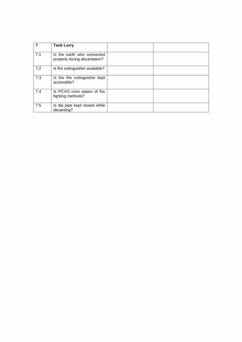
7
Tank Lorry
7.1 Is the earth wire connected properly during decantation?
7.2 Is fire extinguisher available?
7.3 Is the fire extinguisher kept accessible?
7.4 Is PCVO crew aware of fire fighting methods?
7.5 Is dip pipe kept closed while decanting?
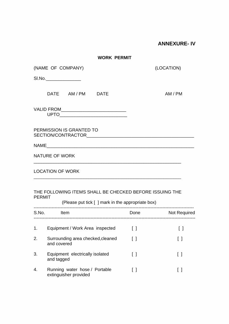
ANNEXURE- IV
WORK PERMIT
(NAME OF COMPANY) (LOCATION) Sl.No.______________ DATE AM / PM DATE AM / PM VALID FROM__________________________
UPTO___________________________ PERMISSION IS GRANTED TO SECTION/CONTRACTOR___________________________________________ NAME___________________________________________________________ NATURE OF WORK ___________________________________________________________ LOCATION OF WORK ___________________________________________________________ THE FOLLOWING ITEMS SHALL BE CHECKED BEFORE ISSUING THE PERMIT (Please put tick [ ] mark in the appropriate box) ----------------------------------------------------------------------------------------------------------- S.No. Item Done Not Required ------------------------------------------------------------------------------------------------------------ 1. Equipment / Work Area inspected [ ] [ ] 2. Surrounding area checked,cleaned [ ] [ ] and covered 3. Equipment electrically isolated [ ] [ ] and tagged 4. Running water hose / Portable [ ] [ ] extinguisher provided
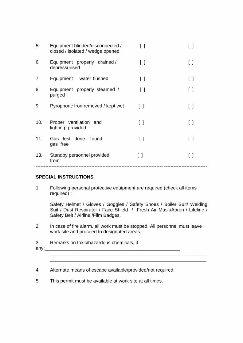
5. Equipment blinded/disconnected / [ ] [ ] closed / isolated / wedge opened 6. Equipment properly drained / [ ] [ ] depressurised 7. Equipment water flushed [ ] [ ] 8. Equipment properly steamed / [ ] [ ] purged 9. Pyrophoric Iron removed / kept wet [ ] [ ]
10. Proper ventilation and [ ] [ ] lighting provided 11. Gas test done , found [ ] [ ] gas free 13. Standby personnel provided [ ] [ ] from -------------------------------------------------------------------------------- --------------------------- SPECIAL INSTRUCTIONS 1. Following personal protective equipment are required (check all items
required) :
Safety Helmet / Gloves / Goggles / Safety Shoes / Boiler Suit/ Welding Suit / Dust Respirator / Face Shield / Fresh Air Mask/Apron / Lifeline / Safety Belt / Airline /Film Badges.
2. In case of fire alarm, all work must be stopped. All personnel must leave
work site and proceed to designated areas. 3. Remarks on toxic/hazardous chemicals, if any:___________________________________________________ ___________________________________________________________ ___________________________________________________________ 4. Alternate means of escape available/provided/not required. 5. This permit must be available at work site at all times.
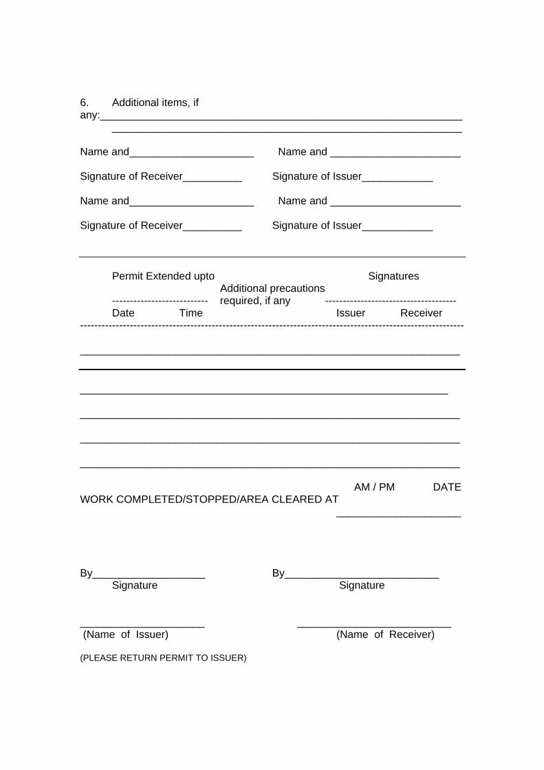
6. Additional items, if any:_____________________________________________________________ ___________________________________________________________ Name and_____________________ Name and ______________________ Signature of Receiver__________ Signature of Issuer____________
Name and_____________________ Name and ______________________ Signature of Receiver__________ Signature of Issuer____________
Permit Extended upto Signatures Additional precautions
--------------------------- required, if any ------------------------------------- Date Time Issuer Receiver
------------------------------------------------------------------------------------------------------------ ________________________________________________________________ ______________________________________________________________ ________________________________________________________________ ________________________________________________________________ ________________________________________________________________ AM / PM DATE WORK COMPLETED/STOPPED/AREA CLEARED AT _____________________ By___________________ By__________________________ Signature Signature _____________________ __________________________ (Name of Issuer) (Name of Receiver) (PLEASE RETURN PERMIT TO ISSUER)
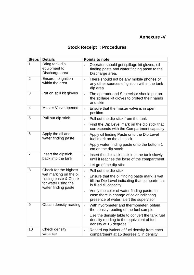
Annexure -V
Stock Receipt : Procedures Steps Details Points to note 1 Bring tank dip
equipment to Discharge area
• Operator should get spillage kit gloves, oil finding paste and water finding paste to the Discharge area.
2 Ensure no ignition within the area
• There should not be any mobile phones or any other sources of ignition within the tank dip area
3 Put on spill kit gloves • The operator and Supervisor should put on the spillage kit gloves to protect their hands and skin
4 Master Valve opened • Ensure that the master valve is in open position
5 Pull out dip stick • Pull out the dip stick from the tank • Find the Dip Level mark on the dip stick that
corresponds with the Compartment capacity 6 Apply the oil and
water finding paste • Apply oil finding Paste onto the Dip Level
fuel mark on the dip stick • Apply water finding paste onto the bottom 1
cm on the dip stock 7 Insert the dipstick
back into the tank • Insert the dip stick back into the tank slowly
until it reaches the base of the compartment • Let go of the dip stick
8 Check for the highest wet marking on the oil finding paste & Check for water using the water finding paste
• Pull out the dip stick • Ensure that the oil finding paste mark is wet
till the Dip Level indicating that compartment is filled till capacity
• Verify the color of water finding paste. In case there is change of color indicating presence of water, alert the supervisor
9 Obtain density reading • With hydrometer and thermometer, obtain the density reading of the fuel sample
• Use the density table to convert the tank fuel density reading to the equivalent of fuel density at 15 degrees C
10 Check density variance
• Record equivalent of fuel density from each compartment at 15 degrees C in density
register • Check variance between density of supplied
product and observed density in density table (at 15 degrees C)
• If the variance between density of supplied product and observed density and the compartment fuel density ia above acceptable limits report to the person in charge
11 Replace equipment and wash hands
• Replace the safety cones/any equipment for isolating,water finding paste, Gasoline Gauging Paste and the spillage kit gloves
• After the tank dip, clean your hands with soap and return to regular duty
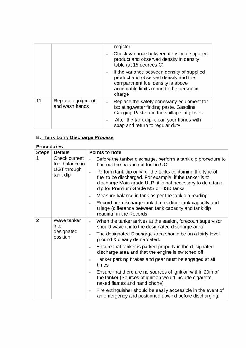
B. Tank Lorry Discharge Process Procedures Steps Details Points to note 1 Check current
fuel balance in UGT through tank dip
• Before the tanker discharge, perform a tank dip procedure to find out the balance of fuel in UGT.
• Perform tank dip only for the tanks containing the type of fuel to be discharged. For example, if the tanker is to discharge Main grade ULP, it is not necessary to do a tank dip for Premium Grade MS or HSD tanks.
• Measure balance in tank as per the tank dip reading • Record pre-discharge tank dip reading, tank capacity and
ullage (difference between tank capacity and tank dip reading) in the Records
2 Wave tanker into designated position
• When the tanker arrives at the station, forecourt supervisor should wave it into the designated discharge area
• The designated Discharge area should be on a fairly level ground & clearly demarcated.
• Ensure that tanker is parked properly in the designated discharge area and that the engine is switched off.
• Tanker parking brakes and gear must be engaged at all times.
• Ensure that there are no sources of ignition within 20m of the tanker (Sources of ignition would include cigarette, naked flames and hand phone)
• Fire extinguisher should be easily accessible in the event of an emergency and positioned upwind before discharging.
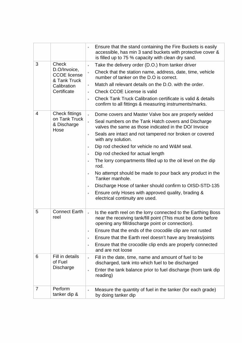
• Ensure that the stand containing the Fire Buckets is easily accessible, has min 3 sand buckets with protective cover & is filled up to 75 % capacity with clean dry sand.
3 Check D.O/Invoice, CCOE license & Tank Truck Calibration Certificate
• Take the delivery order (D.O.) from tanker driver • Check that the station name, address, date, time, vehicle
number of tanker on the D.O is correct. • Match all relevant details on the D.O. with the order. • Check CCOE License is valid • Check Tank Truck Calibration certificate is valid & details
confirm to all fittings & measuring instruments/marks.
4 Check fittings on Tank Truck & Discharge Hose
• Dome covers and Master Valve box are properly welded • Seal numbers on the Tank Hatch covers and Discharge
valves the same as those indicated in the DO/ Invoice • Seals are intact and not tampered nor broken or covered
with any solution. • Dip rod checked for vehicle no and W&M seal. • Dip rod checked for actual length • The lorry compartments filled up to the oil level on the dip
rod. • No attempt should be made to pour back any product in the
Tanker manhole. • Discharge Hose of tanker should confirm to OISD-STD-135 • Ensure only Hoses with approved quality, brading &
electrical continuity are used.
5 Connect Earth reel
• Is the earth reel on the lorry connected to the Earthing Boss near the receiving tank/fill point (This must be done before opening any fill/discharge point or connection).
• Ensure that the ends of the crocodile clip are not rusted • Ensure that the Earth reel doesn’t have any breaks/joints • Ensure that the crocodile clip ends are properly connected
and are not loose 6 Fill in details
of Fuel Discharge
• Fill in the date, time, name and amount of fuel to be discharged, tank into which fuel to be discharged
• Enter the tank balance prior to fuel discharge (from tank dip reading)
7 Perform
tanker dip & • Measure the quantity of fuel in the tanker (for each grade)
by doing tanker dip
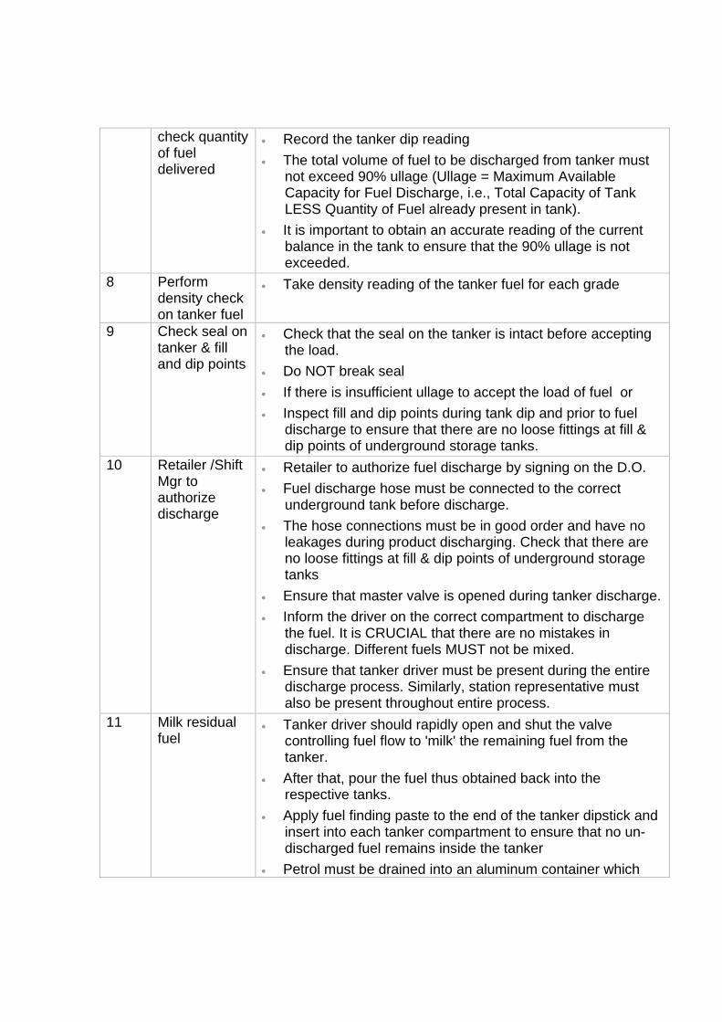
check quantity of fuel delivered
• Record the tanker dip reading • The total volume of fuel to be discharged from tanker must
not exceed 90% ullage (Ullage = Maximum Available Capacity for Fuel Discharge, i.e., Total Capacity of Tank LESS Quantity of Fuel already present in tank).
• It is important to obtain an accurate reading of the current balance in the tank to ensure that the 90% ullage is not exceeded.
8 Perform density check on tanker fuel
• Take density reading of the tanker fuel for each grade
9 Check seal on tanker & fill and dip points
• Check that the seal on the tanker is intact before accepting the load.
• Do NOT break seal • If there is insufficient ullage to accept the load of fuel or • Inspect fill and dip points during tank dip and prior to fuel
discharge to ensure that there are no loose fittings at fill & dip points of underground storage tanks.
10 Retailer /Shift Mgr to authorize discharge
• Retailer to authorize fuel discharge by signing on the D.O. • Fuel discharge hose must be connected to the correct
underground tank before discharge. • The hose connections must be in good order and have no
leakages during product discharging. Check that there are no loose fittings at fill & dip points of underground storage tanks
• Ensure that master valve is opened during tanker discharge. • Inform the driver on the correct compartment to discharge
the fuel. It is CRUCIAL that there are no mistakes in discharge. Different fuels MUST not be mixed.
• Ensure that tanker driver must be present during the entire discharge process. Similarly, station representative must also be present throughout entire process.
11 Milk residual fuel
• Tanker driver should rapidly open and shut the valve controlling fuel flow to 'milk' the remaining fuel from the tanker.
• After that, pour the fuel thus obtained back into the respective tanks.
• Apply fuel finding paste to the end of the tanker dipstick and insert into each tanker compartment to ensure that no un-discharged fuel remains inside the tanker
• Petrol must be drained into an aluminum container which
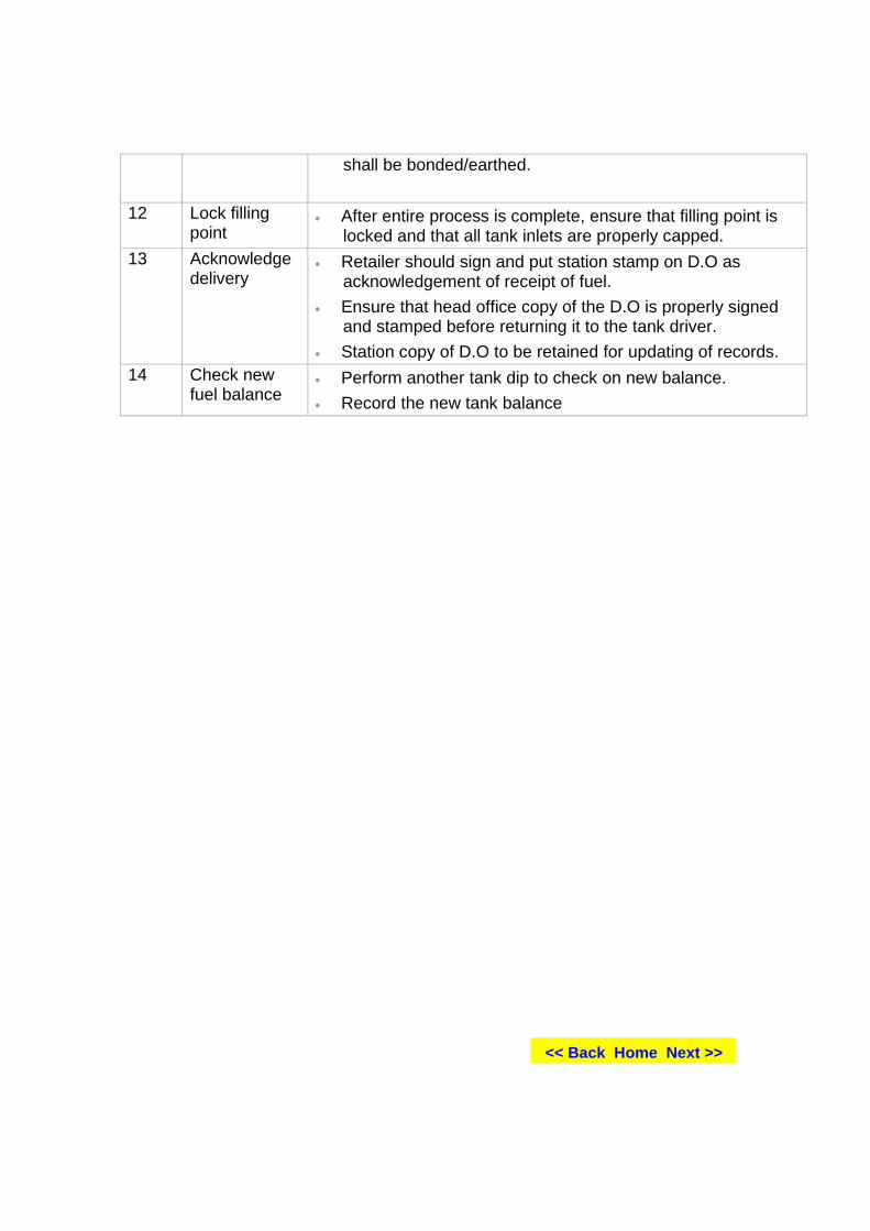
shall be bonded/earthed.
12 Lock filling point
• After entire process is complete, ensure that filling point is locked and that all tank inlets are properly capped.
13 Acknowledge delivery
• Retailer should sign and put station stamp on D.O as acknowledgement of receipt of fuel.
• Ensure that head office copy of the D.O is properly signed and stamped before returning it to the tank driver.
• Station copy of D.O to be retained for updating of records. 14 Check new
fuel balance • Perform another tank dip to check on new balance. • Record the new tank balance
<< Back Home Next >>


![LHD 1 Class Well Deck Operations [.std] - The Ozzfactor · Web view.2 Inspect line handling stations X X X X X _____ (Signature) (Date) .3 Inspect wire handling winch stations X X](https://img.pdfslide.net/doc/110x75/5b4ab5727f8b9a93238c6eae/lhd-1-class-well-deck-operations-std-the-ozzfactor-web-view2-inspect-line.jpg)

![D STD ]STD W T STD WXŒP ST DDDDD ...d ˙˛~q˚std˙˛ tw•p˛]std˙˛w_t˜ std˙˛wxŒp st ddddd (¤ dfid˙˛ƒtw]std˙!ƒstdddddddddddd dddddddddddddddddddddhµµµµµµµ! xstd⁄n"]std#wt˜x](https://img.pdfslide.net/doc/110x75/5f0a52c07e708231d42b1742/d-std-std-w-t-std-wxp-st-ddddd-d-qstd-twapstdwtoe-stdwxp.jpg)