Embed Size (px)
DESCRIPTION
Storage Rings in the FAIR Project at GSI. P. Beller November 4, 2004. Physics at the New Storage Rings. Physics at the New Storage Rings. Physics with Rare Isotope Beams Antiproton Physics Atomic Physics with Highly charged Heavy Ions. Required Properties of the Storage Rings. - PowerPoint PPT Presentation
Citation preview
Storage Rings in the FAIR Project at GSI
P. Beller
November 4, 2004
P. Beller, November 4, 2004
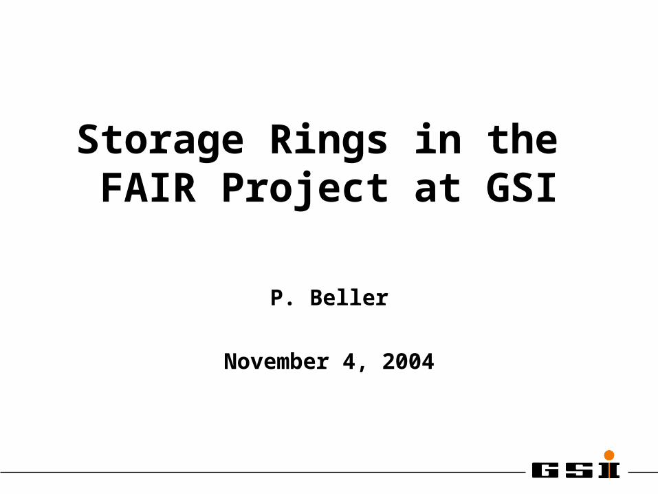
• Physics with Rare Isotope Beams• Antiproton Physics• Atomic Physics with Highly charged Heavy Ions
Physics at the New Storage Rings
• Stochastic Precooling• Electron Cooling• Accumulation• Fast Deceleration (100 - 500 MeV/u)• Deceleration to Low Energies• Fast/Slow Extraction to Cave • In-Ring Experiments• Isochronous Mass Measurements
Physics at the New Storage RingsPhysics at the New Storage Rings
Required Properties of the Storage RingsRequired Properties of the Storage Rings
P. Beller, November 4, 2004
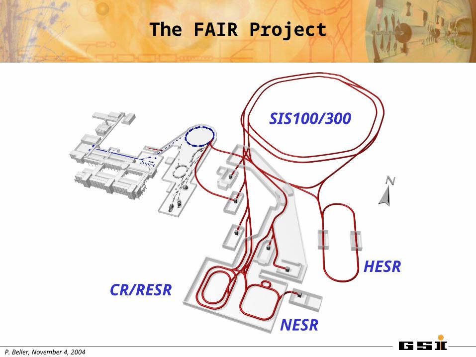
The FAIR Project
SIS100/300
CR/RESR
NESR
HESR
P. Beller, November 4, 2004
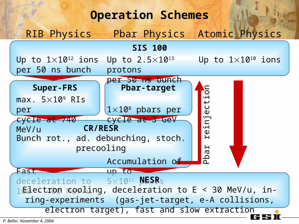
CR/RESRBunch rot., ad. debunching, stoch. precooling
Pbar-targetSuper-FRS
SIS 100
Pb
ar r
ein
ject
ion
Operation Schemes
RIB Physics
Up to 11012 ionsper 50 ns bunch
max. 5109 RIs per cycle at 740 MeV/u
Fast deceleration to 100 - 400 MeV/u
Pbar Physics
Up to 2.51013 protonsper 50 ns bunch
1108 pbars per cycle at 3 GeV
Accumulation of up to51011 pbars
Atomic Physics
Up to 11010 ions
NESRElectron cooling, deceleration to E < 30 MeV/u, in-ring-experiments
(gas-jet-target, e-A collisions, electron target), fast and slow extraction
P. Beller, November 4, 2004
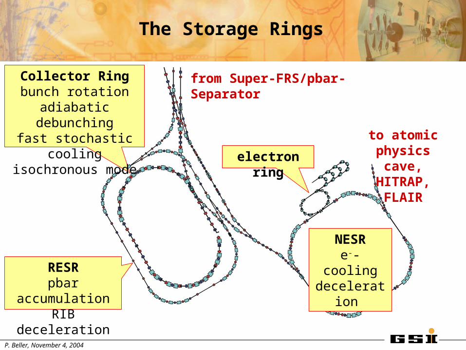
The Storage Rings
from Super-FRS/pbar-Separator
to atomic physics cave,
HITRAP,FLAIR
NESRe--cooling
deceleration RESRpbar accumulationRIB deceleration
Collector Ringbunch rotation
adiabatic debunchingfast stochastic cooling
isochronous mode
electron ring
P. Beller, November 4, 2004
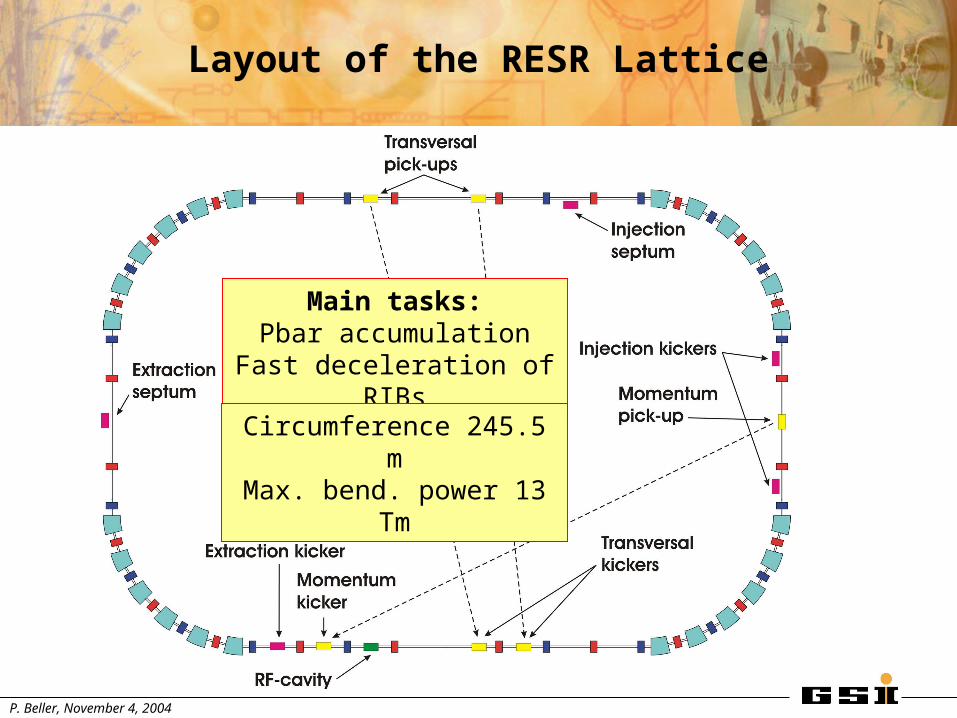
Layout of the RESR Lattice
Main tasks:Pbar accumulation
Fast deceleration of RIBs
Circumference 245.5 mMax. bend. power 13 Tm
P. Beller, November 4, 2004
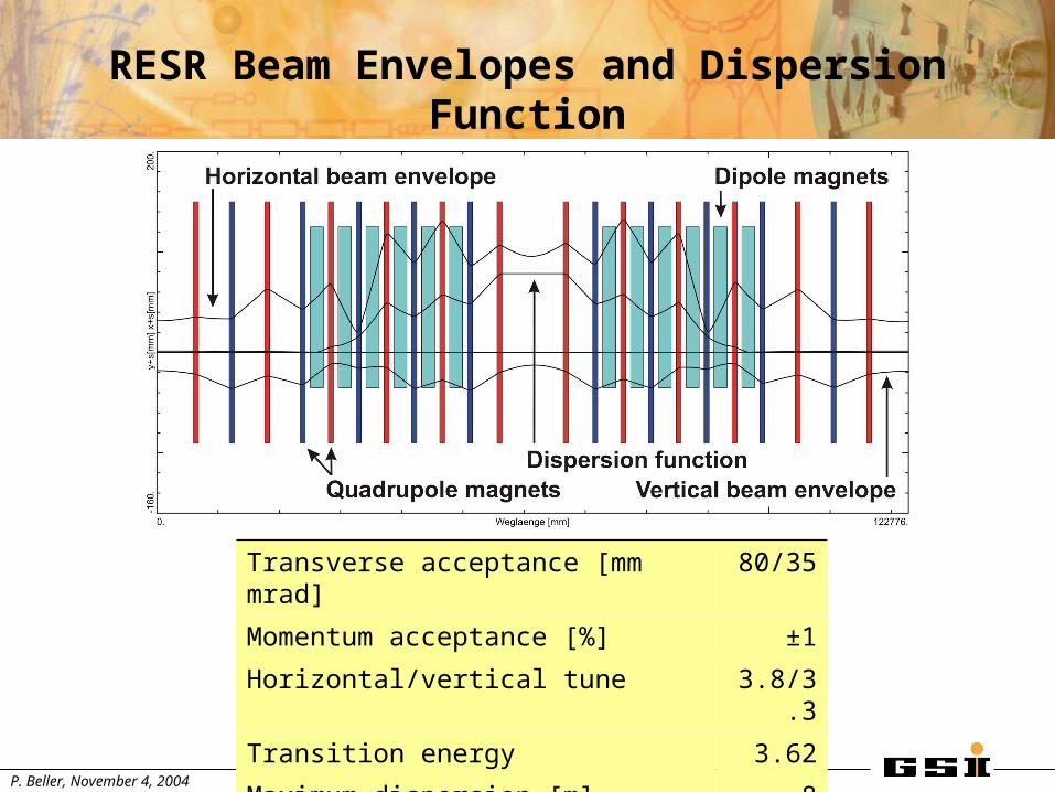
RESR Beam Envelopes and Dispersion Function
Transverse acceptance [mm mrad] 80/35
Momentum acceptance [%] ±1
Horizontal/vertical tune 3.8/3.3
Transition energy 3.62
Maximum dispersion [m] 8
P. Beller, November 4, 2004
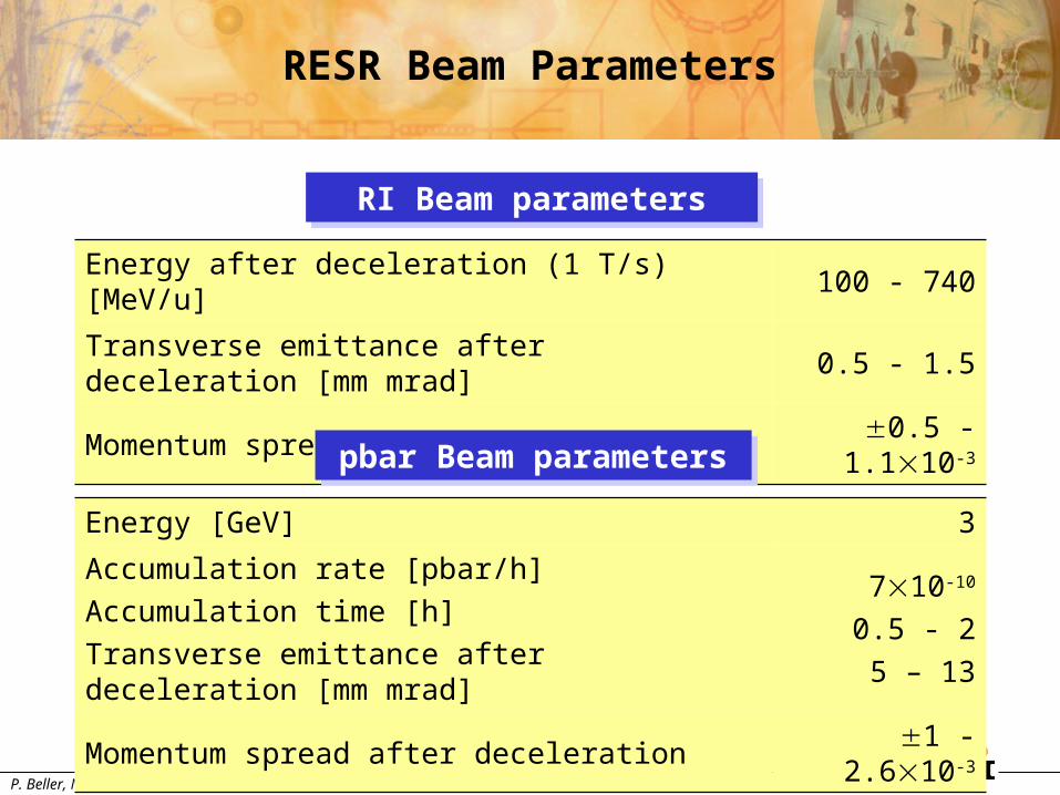
RESR Beam Parameters
RI Beam parametersRI Beam parameters
Energy after deceleration (1 T/s) [MeV/u] 100 - 740
Transverse emittance after deceleration [mm mrad] 0.5 - 1.5
Momentum spread after deceleration0.5 -
1.110-3
pbar Beam parameterspbar Beam parameters
Energy [GeV] 3
Accumulation rate [pbar/h]
Accumulation time [h]
Transverse emittance after deceleration [mm mrad]
710-10
0.5 - 2
5 – 13
Momentum spread after deceleration 1 - 2.610-3
P. Beller, November 4, 2004
0
0.5
1
1.5
2
0 0.5 1 1.5 2 2.5 3 3.5
t [s]
Dip
ole
fie
ld [
T]
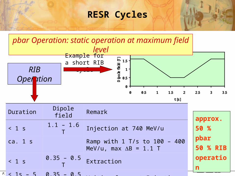
RESR Cycles
Duration Dipole field Remark
< 1 s 1.1 – 1.6 T Injection at 740 MeV/u
ca. 1 s Ramp with 1 T/s to 100 – 400 MeV/u, max B = 1.1 T
< 1 s 0.35 – 0.5 T Extraction
< 1s – 5 min 0.35 – 0.5 T Waiting for next Injection
ca. 1 s Ramp with 1 T/s to injection level
pbar Operation: static operation at maximum field level
RIB Operation
Example for a short RIB cycle
approx.
50 % pbar
50 % RIB
operation
P. Beller, November 4, 2004
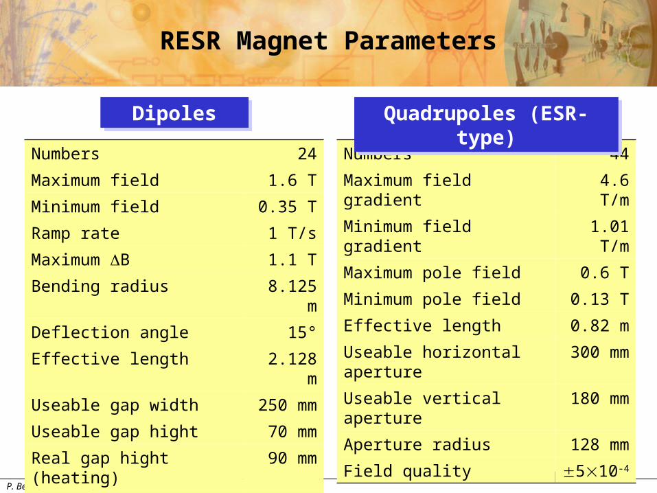
RESR Magnet Parameters
Numbers 24
Maximum field 1.6 T
Minimum field 0.35 T
Ramp rate 1 T/s
Maximum B 1.1 T
Bending radius 8.125 m
Deflection angle 15°
Effective length 2.128 m
Useable gap width 250 mm
Useable gap hight 70 mm
Real gap hight (heating) 90 mm
Field quality 110-4
Numbers 44
Maximum field gradient 4.6 T/m
Minimum field gradient 1.01 T/m
Maximum pole field 0.6 T
Minimum pole field 0.13 T
Effective length 0.82 m
Useable horizontal aperture 300 mm
Useable vertical aperture 180 mm
Aperture radius 128 mm
Field quality 510-4
DipolesDipoles Quadrupoles (ESR-type)Quadrupoles (ESR-type)
P. Beller, November 4, 2004
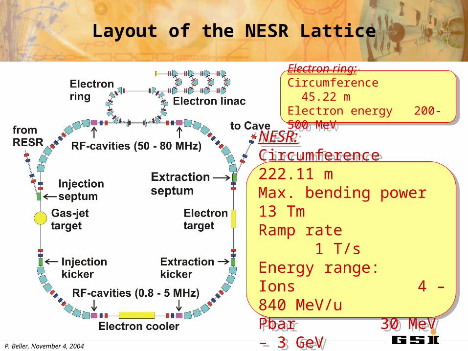
Layout of the NESR Lattice
NESR:Circumference 222.11 mMax. bending power 13 TmRamp rate 1 T/sEnergy range: Ions 4 – 840 MeV/uPbar 30 MeV – 3 GeV
NESR:Circumference 222.11 mMax. bending power 13 TmRamp rate 1 T/sEnergy range: Ions 4 – 840 MeV/uPbar 30 MeV – 3 GeV
Electron ring:Circumference 45.22 mElectron energy 200-500 MeV
Electron ring:Circumference 45.22 mElectron energy 200-500 MeV
P. Beller, November 4, 2004
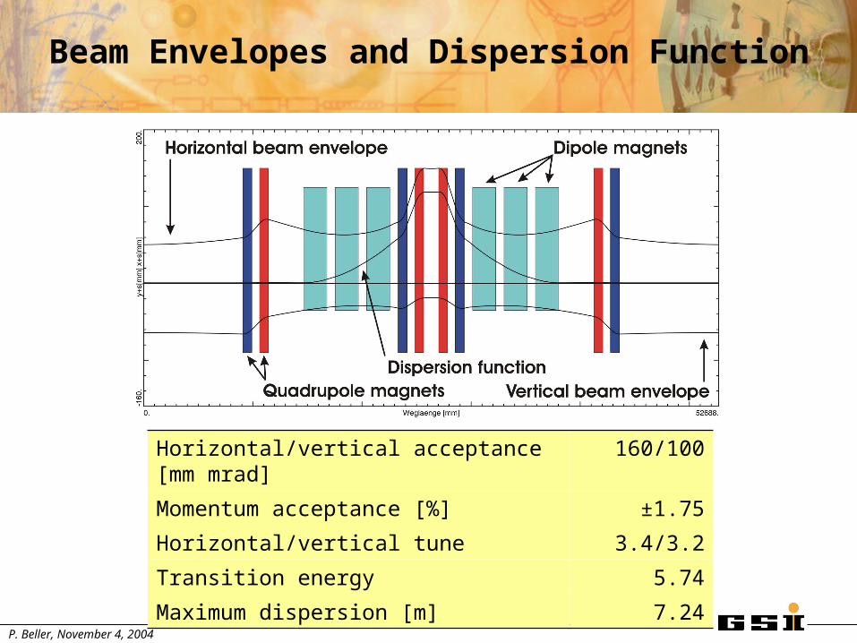
Beam Envelopes and Dispersion Function
Horizontal/vertical acceptance [mm mrad] 160/100
Momentum acceptance [%] ±1.75
Horizontal/vertical tune 3.4/3.2
Transition energy 5.74
Maximum dispersion [m] 7.24
P. Beller, November 4, 2004
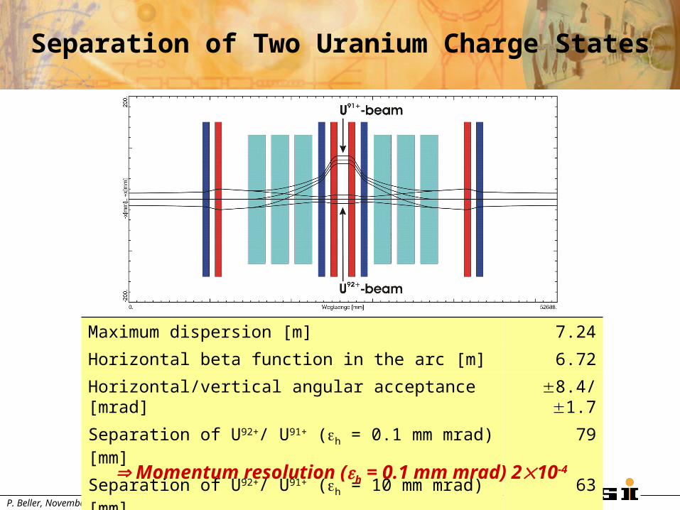
Separation of Two Uranium Charge States
Maximum dispersion [m] 7.24
Horizontal beta function in the arc [m] 6.72
Horizontal/vertical angular acceptance [mrad] 8.4/1.7
Separation of U92+/ U91+ (h = 0.1 mm mrad) [mm] 79
Separation of U92+/ U91+ (h = 10 mm mrad) [mm] 63
Momentum resolution (h = 0.1 mm mrad) 210-4
P. Beller, November 4, 2004
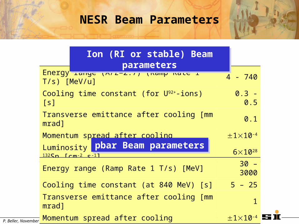
NESR Beam Parameters
Energy range (A/Z=2.7) (Ramp Rate 1 T/s) [MeV/u] 4 - 740
Cooling time constant (for U92+-ions) [s] 0.3 - 0.5
Transverse emittance after cooling [mm mrad] 0.1
Momentum spread after cooling 110-4
Luminosity at internal gas target for 132Sn [cm-2 s-1] 61028
pbar Beam parameterspbar Beam parameters
Ion (RI or stable) Beam parametersIon (RI or stable) Beam parameters
Energy range (Ramp Rate 1 T/s) [MeV] 30 – 3000
Cooling time constant (at 840 MeV) [s] 5 – 25
Transverse emittance after cooling [mm mrad] 1
Momentum spread after cooling 110-4
P. Beller, November 4, 2004
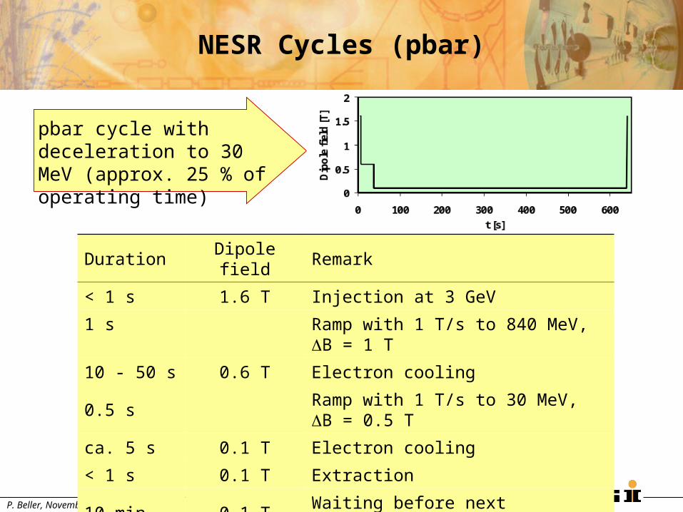
NESR Cycles (pbar)
Duration Dipole field Remark
< 1 s 1.6 T Injection at 3 GeV
1 s Ramp with 1 T/s to 840 MeV, B = 1 T
10 - 50 s 0.6 T Electron cooling
0.5 s Ramp with 1 T/s to 30 MeV, B = 0.5 T
ca. 5 s 0.1 T Electron cooling
< 1 s 0.1 T Extraction
10 min 0.1 T Waiting before next Injection
1.5 s Ramp with 1 T/s to injection level
pbar cycle with deceleration to 30 MeV (approx. 25 % of operating time)
P. Beller, November 4, 2004
0
0.5
1
1.5
2
0 2 4 6 8 10 12
t [s]
Dip
ole
fie
ld [
T]
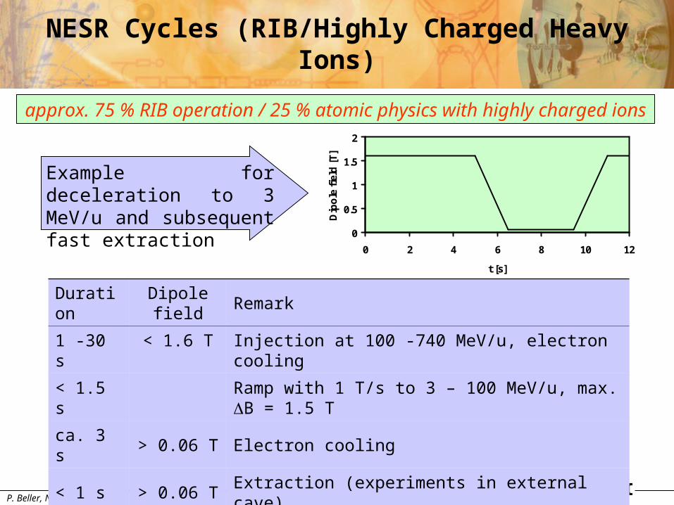
NESR Cycles (RIB/Highly Charged Heavy Ions)
Duration Dipole field Remark
1 -30 s < 1.6 T Injection at 100 -740 MeV/u, electron cooling
< 1.5 s Ramp with 1 T/s to 3 – 100 MeV/u, max. B = 1.5 T
ca. 3 s > 0.06 T Electron cooling
< 1 s > 0.06 T Extraction (experiments in external cave)
< 15 min > 0.06 T In ring experiments, waiting for next injection
< 1.5 s Ramp with 1 T/s to injection level
Example for deceleration to 3 MeV/u and subsequent fast extraction
approx. 75 % RIB operation / 25 % atomic physics with highly charged ions
P. Beller, November 4, 2004
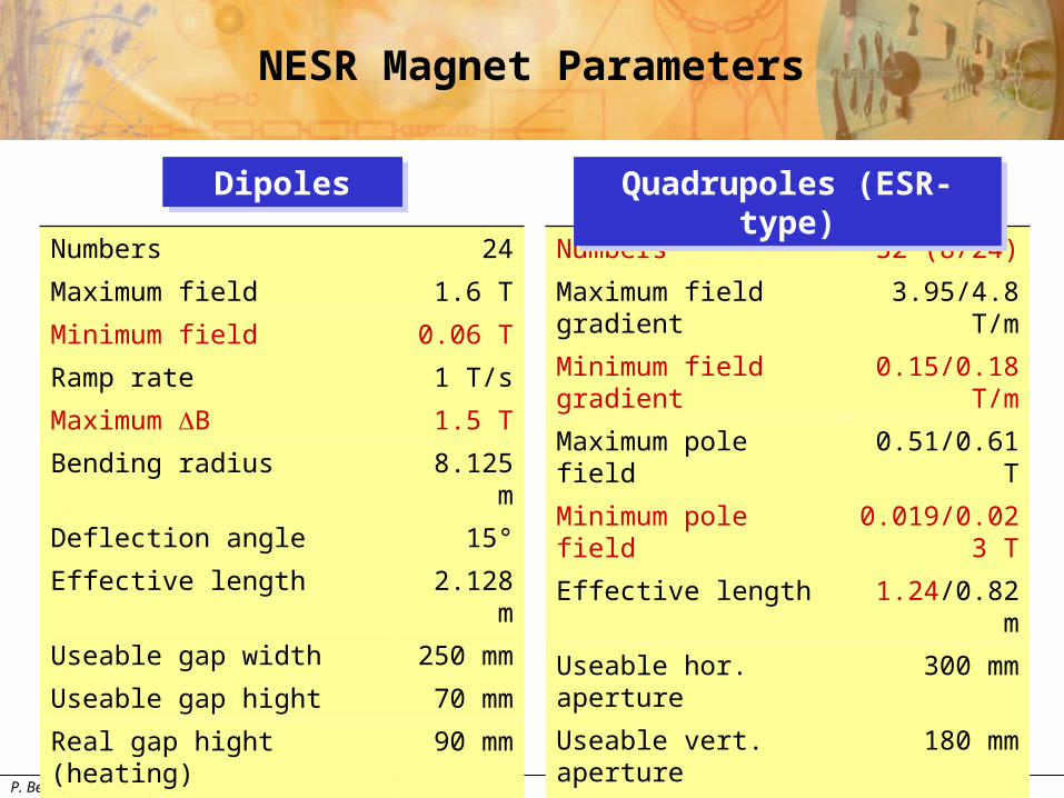
NESR Magnet Parameters
Numbers 24
Maximum field 1.6 T
Minimum field 0.06 T
Ramp rate 1 T/s
Maximum B 1.5 T
Bending radius 8.125 m
Deflection angle 15°
Effective length 2.128 m
Useable gap width 250 mm
Useable gap hight 70 mm
Real gap hight (heating) 90 mm
Field quality 110-4
Numbers 32 (8/24)
Maximum field gradient 3.95/4.8 T/m
Minimum field gradient 0.15/0.18 T/m
Maximum pole field 0.51/0.61 T
Minimum pole field 0.019/0.023 T
Effective length 1.24/0.82 m
Useable hor. aperture 300 mm
Useable vert. aperture 180 mm
Aperture radius 128 mm
Field quality 510-4
DipolesDipoles Quadrupoles (ESR-type)Quadrupoles (ESR-type)
P. Beller, November 4, 2004
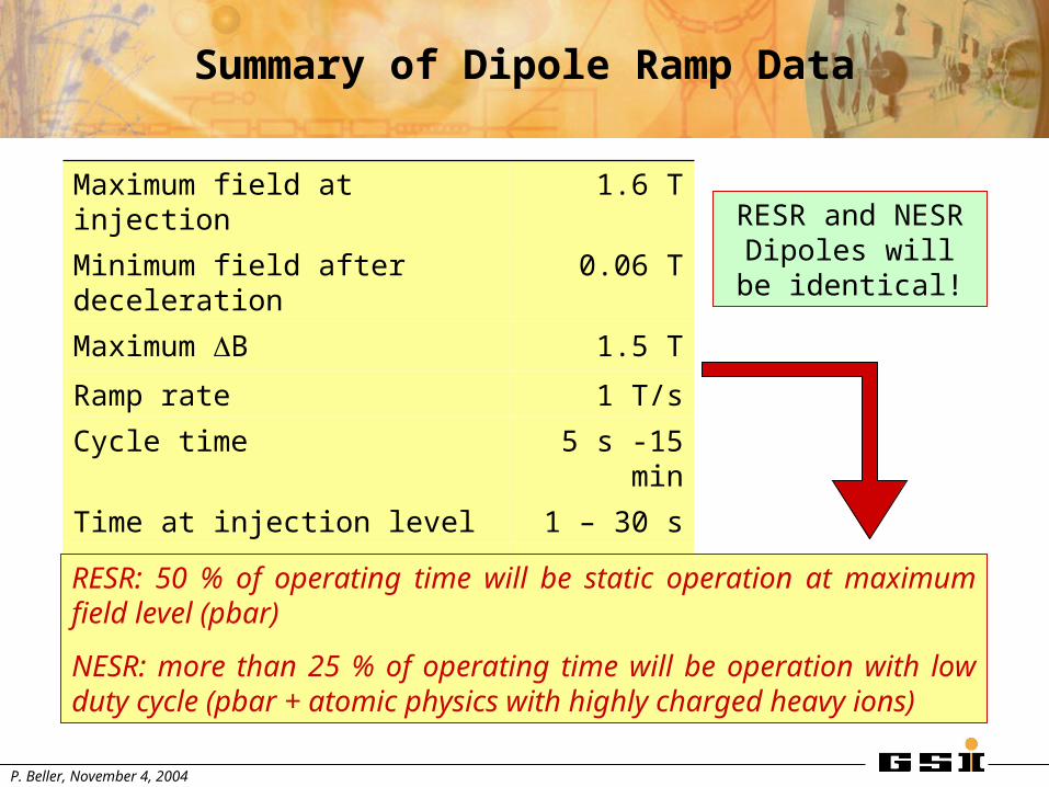
Summary of Dipole Ramp Data
Maximum field at injection 1.6 T
Minimum field after deceleration 0.06 T
Maximum B 1.5 T
Ramp rate 1 T/s
Cycle time 5 s -15 min
Time at injection level 1 – 30 s
Time at intermediate level 10 – 50 s
Time at extraction level 1 s – 15 min
RESR: 50 % of operating time will be static operation at maximum field level (pbar)
NESR: more than 25 % of operating time will be operation with low duty cycle (pbar + atomic physics with highly charged heavy ions)
RESR and NESR Dipoles will be
identical!