Embed Size (px)
Citation preview

County of Los Angeles Department of Public Works
Stormwater Best Management Practice Design and Maintenance Manual
For Publicly Maintained
Storm Drain Systems
August 2010

THIS PAGE INTENTIONALLY LEFT BLANK

Stormwater BMP Design and Maintenance Manual
i 8/23/2010
Table of Contents
1. INTRODUCTION .............................................................................................................. 1-1
PURPOSE .................................................................................................................................... 1-1 OTHER STORMWATER BMP SELECTION AND DESIGN MANUALS .................................................................. 1-1 CONTENT AND ORGANIZATION OF THIS MANUAL .................................................................................... 1-2 GENERAL CONSIDERATIONS ............................................................................................................. 1-2
Maintenance Responsibility .................................................................................................... 1-2 Pretreatment ........................................................................................................................ 1-3 Infiltration ............................................................................................................................ 1-3 Biofiltration ........................................................................................................................... 1-4 Bioretention .......................................................................................................................... 1-4 Filtration............................................................................................................................... 1-4 Wetpools .............................................................................................................................. 1-4 Oil/Water Separation ............................................................................................................. 1-5 “On-line” and “Off-line” Facilities ............................................................................................ 1-5 Hydromodification Control ...................................................................................................... 1-6 Unit Process-Based BMP Selection and Design ......................................................................... 1-7
2. DRY EXTENDED DETENTION BASINS ............................................................................. 2-1
DEFINITION ................................................................................................................................ 2-1 GENERAL CONSTRAINTS AND SITING CONSIDERATIONS ........................................................................... 2-1 MULTI-USE OPPORTUNITIES ............................................................................................................ 2-1 DRY EXTENDED DETENTION BASIN DESIGN SPECIFICATIONS .................................................................... 2-2
Basin Sizing and Geometry ..................................................................................................... 2-2 Soils Considerations .............................................................................................................. 2-2 Energy Dissipation ................................................................................................................. 2-3 Forebay ................................................................................................................................ 2-3 Vegetation ............................................................................................................................ 2-3 Outlet Structure and Drawdown Time ..................................................................................... 2-4 Emergency Spillway............................................................................................................... 2-6 Side Slopes ........................................................................................................................... 2-7 Embankments ....................................................................................................................... 2-7 Fencing ................................................................................................................................ 2-8 Right-of-Way ........................................................................................................................ 2-8 Maintenance Access .............................................................................................................. 2-8 Landscaping ......................................................................................................................... 2-9 Restricted Construction Materials ............................................................................................ 2-9
DRY EXTENDED DETENTION BASINS MAINTENANCE STANDARDS .............................................................. 2-14 General Requirements ......................................................................................................... 2-14 Maintenance Standards........................................................................................................ 2-15
3. VEGETATED SWALES ...................................................................................................... 3-1
DEFINITION ................................................................................................................................ 3-1 GENERAL CONSTRAINTS AND SITING CONSIDERATIONS ........................................................................... 3-1 MULTI-USE OPPORTUNITIES ............................................................................................................ 3-1 VEGETATED SWALE DESIGN SPECIFICATIONS ........................................................................................ 3-2
Geotechnical Considerations ................................................................................................... 3-2 Sizing ................................................................................................................................... 3-2 Swale Geometry .................................................................................................................... 3-5 Bottom Slope ........................................................................................................................ 3-6 Water Depth and Dry Weather Flow Drain ............................................................................... 3-6 Energy Dissipation ................................................................................................................. 3-6

Stormwater BMP Design and Maintenance Manual
ii 8/23/2010
Flow Spreaders ..................................................................................................................... 3-7 Check Dams ......................................................................................................................... 3-8 Underdrains .......................................................................................................................... 3-8 Swale Divider ........................................................................................................................ 3-9 Soils ..................................................................................................................................... 3-9 Vegetation ............................................................................................................................ 3-9 Restricted Construction Materials .......................................................................................... 3-11
VEGETATED SWALE MAINTENANCE STANDARDS ................................................................................... 3-14 General Requirements ......................................................................................................... 3-14 Maintenance Standards........................................................................................................ 3-15
4. FILTER STRIPS ............................................................................................................... 4-1
DEFINITION ................................................................................................................................ 4-1 GENERAL CONSTRAINTS AND SITING CONSIDERATIONS ........................................................................... 4-1 MULTI-USE OPPORTUNITIES ............................................................................................................ 4-1 FILTER STRIP DESIGN SPECIFICATIONS ............................................................................................... 4-1
Location ............................................................................................................................... 4-1 Tributary Area Length ............................................................................................................ 4-2 Sizing ................................................................................................................................... 4-2 Geometry ............................................................................................................................. 4-3 Energy Dissipation / Level Spreading ...................................................................................... 4-3 Access .................................................................................................................................. 4-4 Water depth and Velocity ....................................................................................................... 4-4 Soils ..................................................................................................................................... 4-4 Vegetation ............................................................................................................................ 4-5 Restricted Construction Materials ............................................................................................ 4-5
FILTER STRIP OPERATIONS AND MAINTENANCE ..................................................................................... 4-7 General Requirements ........................................................................................................... 4-7 Maintenance Standards.......................................................................................................... 4-7
5. BIORETENTION .............................................................................................................. 5-1
DEFINITION ................................................................................................................................ 5-1 GENERAL CONSTRAINTS AND SITING CONSIDERATIONS ........................................................................... 5-1 MULTI-USE OPPORTUNITIES ............................................................................................................ 5-1 BIORETENTION DESIGN SPECIFICATIONS ............................................................................................. 5-1
Geotechnical and Landscape Considerations ............................................................................ 5-1 Pretreatment ........................................................................................................................ 5-2 Sizing Criteria ....................................................................................................................... 5-2 Geometry ............................................................................................................................. 5-5 Flow Entrance and Energy Dissipation ..................................................................................... 5-5 Underdrains .......................................................................................................................... 5-5 Overflow .............................................................................................................................. 5-7 Hydraulic Restriction Layers ................................................................................................... 5-7 Planting/Storage Media .......................................................................................................... 5-7 Plants................................................................................................................................... 5-9 Restricted Construction Materials .......................................................................................... 5-10
BIORETENTION OPERATIONS AND MAINTENANCE ................................................................................. 5-12 General Requirements ......................................................................................................... 5-12 Maintenance Standards........................................................................................................ 5-13
6. INFILTRATION FACILITIES ............................................................................................ 6-1
DEFINITION ................................................................................................................................ 6-1 GENERAL CONSTRAINTS AND SITING CONSIDERATIONS ........................................................................... 6-1

Stormwater BMP Design and Maintenance Manual
iii 8/23/2010
MULTI-USE OPPORTUNITIES ............................................................................................................ 6-2 INFILTRATION FACILITY DESIGN SPECIFICATIONS .................................................................................. 6-2
Geotechnical Considerations ................................................................................................... 6-2 Site Geotechnical Investigation ............................................................................................... 6-3 Setbacks .............................................................................................................................. 6-3 Pretreatment ........................................................................................................................ 6-3 Sizing Criteria ....................................................................................................................... 6-4 Facility Geometry .................................................................................................................. 6-6 Embankments ....................................................................................................................... 6-7 Additional Control Functions ................................................................................................... 6-7 Drainage .............................................................................................................................. 6-8 Emergency Overflow ............................................................................................................. 6-8 Vegetation ............................................................................................................................ 6-8 Maintenance Access .............................................................................................................. 6-9 Construction ....................................................................................................................... 6-10 Landscaping ....................................................................................................................... 6-10 Restricted Construction Materials .......................................................................................... 6-11
INFILTRATION FACILITY OPERATIONS AND MAINTENANCE ...................................................................... 6-14 General Requirements ......................................................................................................... 6-14 Maintenance Standards........................................................................................................ 6-16
7. STORMWATER WETLAND BASINS .................................................................................. 7-1
DEFINITION ................................................................................................................................ 7-1 GENERAL CONSTRAINTS AND SITING CONSIDERATIONS ........................................................................... 7-1 MULTI-USE OPPORTUNITIES ............................................................................................................ 7-2 STORMWATER WETLAND BASIN DESIGN SPECIFICATIONS......................................................................... 7-2
Basin Sizing and Geometry ..................................................................................................... 7-2 Water Supply ........................................................................................................................ 7-3 Soils Considerations .............................................................................................................. 7-3 Buffer Zone .......................................................................................................................... 7-4 Energy Dissipation ................................................................................................................. 7-4 Vegetation ............................................................................................................................ 7-4 Outlet Structure and Spillway ................................................................................................. 7-4 Side Slopes ........................................................................................................................... 7-5 Embankments ....................................................................................................................... 7-5 Fencing ................................................................................................................................ 7-6 Right-of-Way ........................................................................................................................ 7-6 Maintenance Access .............................................................................................................. 7-6 Landscaping Outside of the Facility ......................................................................................... 7-7 Restricted Construction Materials ............................................................................................ 7-7
STORMWATER WETLAND BASIN MAINTENANCE STANDARDS .................................................................... 7-11 General Requirements ......................................................................................................... 7-11 Maintenance Standards........................................................................................................ 7-12
8. SAND FILTERS ................................................................................................................ 8-1
DEFINITION ................................................................................................................................ 8-1 GENERAL CONSTRAINTS AND SITING CONSIDERATIONS ........................................................................... 8-1 SAND FILTER DESIGN SPECIFICATIONS ............................................................................................... 8-1
Basin Sizing and Geometry ..................................................................................................... 8-1 Sizing Methodology ............................................................................................................... 8-2 Sand Specification ................................................................................................................. 8-4 Underdrains .......................................................................................................................... 8-5 Pretreatment ........................................................................................................................ 8-6

Stormwater BMP Design and Maintenance Manual
iv 8/23/2010
Flow Spreading ..................................................................................................................... 8-6 Vegetation ............................................................................................................................ 8-7 Emergency Overflow Structure ............................................................................................... 8-7 Side Slopes ........................................................................................................................... 8-7 Embankments ....................................................................................................................... 8-7 Fencing ................................................................................................................................ 8-8 Right-of-Way ........................................................................................................................ 8-8 Maintenance Access .............................................................................................................. 8-8 Landscaping Outside of the Facility ......................................................................................... 8-9 Restricted Construction Materials ............................................................................................ 8-9
SAND FILTER MAINTENANCE STANDARDS .......................................................................................... 8-11 General Requirements ......................................................................................................... 8-11 Maintenance Standards........................................................................................................ 8-11
9. PROPRIETARY DEVICES ................................................................................................. 9-1
DEFINITION ................................................................................................................................ 9-1 GENERAL DESIGN SPECIFICATIONS .................................................................................................... 9-2 EXPECTED PERFORMANCE ................................................................................................................ 9-2 SIZING ...................................................................................................................................... 9-3 OPERATION AND MAINTENANCE ........................................................................................................ 9-3
Hydrodynamic Separation Devices .......................................................................................... 9-3 Catch Basin Inserts ............................................................................................................... 9-4 Cartridge filters ..................................................................................................................... 9-4 Biotreatment Devices ............................................................................................................ 9-4
ONLINE RESOURCES ...................................................................................................................... 9-4
10. REFERENCES ............................................................................................................. 10-1
11. ACKNOWLEDGMENTS ............................................................................................... 11-1
DOCUMENT PREPARATION TEAM ..................................................................................................... 11-1 SPECIAL ACKNOWLEDGEMENT ......................................................................................................... 11-1

Stormwater BMP Design and Maintenance Manual
v 8/23/2010
Appendix A Glossary Appendix B BMP Sizing Worksheets Appendix C Pond Outlet Sizing Examples Appendix D Flow Splitter Design Specification Appendix E Facility Inspection Appendix F Facility Inspection and Maintenance Checklists Appendix G Policy for New Percolation Basin Testing, Design, and Maintenance
List of Tables Table 1-1: Unit Operations and Processes Provided by Common BMPs and BMP Components. 1-9 Table 1-2: BMP Practicability Screening Matrix .................................................................. 1-10 Table 2-1: Dry Extended Detention Pond Routine and Major Maintenance Quick Guide ........ 2-15 Table 2-2: Routine Maintenance Standards - Extended Detention Basins ............................ 2-16 Table 2-3: Major Maintenance Standards - Extended Detention Basins ............................... 2-17 Table 3-1: Vegetated Swale Routine and Major Maintenance Quick Guide ........................... 3-15 Table 3-2: Routine Maintenance Standards - Vegetated Swales .......................................... 3-16 Table 3-3: Major Maintenance Standards - Vegetated Swales ............................................. 3-17 Table 4-1: Filter Strip Routine and Major Maintenance Quick Guide ...................................... 4-8 Table 4-2: Routine Maintenance – Filter Strips .................................................................... 4-8 Table 4-3: Major Maintenance – Filter Strips ....................................................................... 4-9 Table 5-1: Bioretention Routine and Major Maintenance Quick Guide ................................. 5-13 Table 5-2: Routine Maintenance – Bioretention ................................................................. 5-14 Table 5-3: Major Maintenance – Bioretention .................................................................... 5-15 Table 6-1: Infiltration Facility Routine and Major Maintenance Quick Guide ......................... 6-16 Table 6-2: Routine Maintenance – Infiltration Facilities ...................................................... 6-17 Table 6-3: Major Maintenance – Infiltration Facilities ......................................................... 6-18 Table 7-1: Recommended Distribution of Depths in Wetland Basin ...................................... 7-3 Table 7-2: Wetland Basin Routine and Major Maintenance Quick Guide .............................. 7-12 Table 7-3: Routine Maintenance Standards – Stormwater Wetland Basins .......................... 7-13 Table 7-4: Major Maintenance Standards – Stormwater Wetland Basins ............................ 7-14 Table 8-1: Sand filter Routine and Major Maintenance Quick Guide .................................... 8-11 Table 8-2: Routine Maintenance – Sand Filters ................................................................. 8-12 Table 8-3: Major Maintenance – Sand Filters .................................................................... 8-13 Table 9-1: Proprietary Device Manufacturer Websites .......................................................... 9-5

Stormwater BMP Design and Maintenance Manual
vi 8/23/2010
List of Figures
Figure 1-1: Difference Between On-line, Off-line, and In-stream Controls. ........................... 1-6 Figure 2-1: Detention Pond ............................................................................................. 2-10 Figure 2-2: Perforated Riser Outlet .................................................................................. 2-11 Figure 2-3: Multiple Orifice Outlet ................................................................................... 2-12 Figure 2-4: Spillway........................................................................................................ 2-13 Figure 3-1: Vegetated Swale ........................................................................................... 3-12 Figure 3-2: Flow Spreader and Check Dam ...................................................................... 3-13 Figure 4-1: Filter Strip ...................................................................................................... 4-6 Figure 5-1: Bioretention Area .......................................................................................... 5-11 Figure 6-1: Infiltration Basin ........................................................................................... 6-12 Figure 6-2: Infiltration Trench ......................................................................................... 6-13 Figure 7-1: Stormwater Wetland Basin .............................................................................. 7-8 Figure 7-2: Riser Outlet .................................................................................................... 7-9 Figure 7-3: Inverted Pipe Outlet ...................................................................................... 7-10 Figure 8-1: Sand Filter .................................................................................................... 8-10

Stormwater BMP Design and Maintenance Manual Introduction
1-1 8/23/2010
1. INTRODUCTION
Purpose
Stormwater treatment best management practices (BMPs) are an integral part of stormwater management plans for new development and significant redevelopment projects. Certain new development and redevelopment projects are required to submit drainage concept and stormwater quality plans that show details of treatment facilities designed to mitigate potential impacts to surface water and groundwater quality. These treatment facilities can be either privately or publicly maintained. The purpose of this BMP design and maintenance manual is to provide design criteria and guidelines for developers, to assist the County in the review and approval of stormwater treatment BMP designs, and to provide guidance on BMP maintenance requirements for those devices that will be publicly maintained.
Other Stormwater BMP Selection and Design Manuals
Three previous stormwater BMP manuals have been published by the County of Los Angeles Department of Public Works: 1. Development Planning for Stormwater Management – A Manual for the Standard Urban
Stormwater Mitigation Plan (SUSMP), dated September 2002, prepared by the LACDPW; and 2. Technical Manual for Stormwater Best Management Practices in the County of Los Angeles,
draft dated February 2004, prepared by the LACDPW. 3. Los Angeles County-Wide Structural BMP Prioritization Methodology, dated April 2006,
prepared by Geosyntec Consultants and Heal the Bay. These three manuals were designed to assist the development community in Los Angeles County in selecting and designing site-specific post-construction BMPs to minimize pollutant impacts from urban stormwater runoff. These manuals also describe the legal framework for the development planning program within the County of Los Angeles. In contrast, this manual does not provide information on plan submittal requirements, but instead provides detailed guidance on BMP sizing, design specifications, and maintenance requirements. The design specifications contained in this manual were based on and are consistent with the general design principles contained in the three previous LACDPW manuals. California Stormwater Quality Association (CASQA) released four Stormwater Best Management Practice Handbooks in January 2003. The design guidance contained in the New Development and Redevelopment Best Management Practice Handbook was also used in the preparation of this manual. Design specifications were also drawn from a number of other sources:
• King County Surface Water Design Manual, King County Department of Natural Resources, Seattle, Washington. August 2005.

Stormwater BMP Design and Maintenance Manual Introduction
1-2 8/23/2010
• Technical Guidance Manual for Stormwater Quality Control Measures, Ventura Countywide Stormwater Quality Management Program. July 2002.
• Hydrology Manual, Los Angeles County Department of Public Works. January 2006.
• Design Manual - Debris Dams and Basins, Los Angeles County Flood Control District.
October, 1979.
• Design Manual - Hydraulic, Los Angeles County Flood Control District. March 1982.
Content and Organization of this Manual
Chapter 1 serves as an introduction and summarizes available options for treatment of stormwater. Chapters 2 - 10 provide design specifications and maintenance guidance for specific types of treatment. The appendices include a glossary (Appendix A); sample worksheets for BMP sizing (Appendix B); design specifications for flow diversion structures (Appendix C); facility inspection procedures (Appendix D); facility inspection and maintenance checklists (Appendix E); and the Policy for New Percolation Basin Testing, Design, and Maintenance dated October 10, 2007 (Appendix F).
General Considerations
Runoff treatment facilities are designed to remove pollutants contained in stormwater runoff. The pollutants of concern, depending on the watershed, may include trash, debris, and sediment; metals such as copper, lead, and zinc; nutrients (e.g., nitrogen and phosphorous); certain bacteria and viruses; mineral salts such as chloride; and organic chemicals such as petroleum hydrocarbons and pesticides. Methods of pollutant removal include sedimentation/settling, filtration, plant uptake, ion exchange, adsorption, and microbially-mediated decomposition. Floatable pollutants such as oil, debris, and scum can be removed with separator structures. Runoff treatment facilities can also be designed to reduce runoff volume, thereby reducing pollutant loading to receiving waters. Runoff treatment facility types and common terms used in runoff treatment are discussed below.
Maintenance Responsibility
Maintenance is required for all types of runoff treatment facilities. Upon acceptance into the Flood Control District, LACDPW will assume operation and maintenance responsibilities for the BMPs contained in this manual. The devices shall be placed within public right-of-ways or Flood Control District easements. The primary purpose of BMPs is water quality treatment. However, an ancillary benefit of certain BMPs is the provision of habitat for aquatic and terrestrial wildlife. The quality and extent of such habitat may be affected by maintenance activities required to ensure the continued water quality performance of the BMP. In situations where there is potential for habitat to attract threatened or endangered species, the project proponent must coordinate with and develop written agreements with the California Department of Fish and Game or the US Fish and Wildlife service. These agreements must ensure that the BMPs are considered treatment facilities and not waters of the United States, and that long term operation and maintenance requirements are acceptable to these agencies.

Stormwater BMP Design and Maintenance Manual Introduction
1-3 8/23/2010
Pretreatment
Pretreatment must be provided for filtration and infiltration facilities, and other facilities whose function could be adversely affected by sediment or other pollutants. Pretreatment may also be provided for water quality detention basins and other BMPs to facilitate the routine removal of sediment, trash, and debris, and to increase the longevity of the downstream BMPs. Runoff from undeveloped hillsides and canyons should be routed to debris basins in compliance with County requirements and, where feasible, routed around downstream treatment BMPs. Pretreatment may be provided by presettling basins or forebays (small detention basins), vegetated swales, filter strips, hydrodynamic separators, and catch basin inserts. Debris controls as described in the Los Angeles County Sedimentation Manual may also be appropriate for pretreatment. Source control activities, implemented per the SUSMP requirements, minimize the introduction of pollutants into stormwater runoff and also help to protect filtration and infiltration facilities. Effort should be made early in the site planning stages to minimize runoff from impervious areas by grading toward landscaped areas, disconnecting downspouts, and using pervious conveyances prior to discharging to the storm drain system. These low impact development (LID) practices can reduce the size and maintenance burden of downstream, end-of-pipe BMPs.
Infiltration
Infiltration refers to the use of the filtration, adsorption, and biological decomposition properties of soils to remove pollutants prior to the intentional routing of runoff to the subsurface for groundwater recharge. Infiltration BMPs include infiltration basins and trenches. Infiltration can provide multiple benefits, including pollutant removal, peak flow control, groundwater recharge, and flood control. However, conditions that can limit the use of infiltration include soil properties and potential adverse impacts on groundwater quality. To adequately address the protection of groundwater when evaluating infiltration, site soils must be determined to be suitable by conducting a geotechnical investigation that includes an in-situ percolation test, per the Policy for New Percolation Basin Testing, Design, and Maintenance (October 10, 2007, or as amended (provided in Appendix G)) and determination of minimum depth to groundwater. Soils must have sufficient organic content and sorption capacity to remove certain pollutants, but must be coarse enough to infiltrate runoff in a reasonable amount of time (e.g., < 72 hours). Examples of suitable soils are silty and sandy loams. Coarser soils, such as gravelly sands, have limited organic content and high permeability and therefore present a potential risk to groundwater from certain pollutants, especially in areas of shallow groundwater. NPDES permits often specify a water table distance separation of ten feet depth or more to protect groundwater quality. These permits also specify that infiltration BMPs are not allowed for areas of industrial activity or areas subject to high vehicular traffic (25,000 or greater average daily traffic (ADT) on the main roadway or 15,000 or more ADT on any intersecting roadway), nor are they allowed within 100 feet from any drinking water well unless appropriate pretreatment for the pollutants of concern is provided. Incidental infiltration that occurs in other types of BMPs, such as dry extended detention basins, vegetation swales, filter strips, and bioretention areas, generally pose a lesser risk to groundwater quality as treatment is provided in the BMP prior to infiltration.

Stormwater BMP Design and Maintenance Manual Introduction
1-4 8/23/2010
Biofiltration
Biofiltration utilizes vegetation in conjunction with slow and shallow-depth flow for runoff treatment. As runoff passes through the vegetation, the combined effects of filtration, infiltration, adsorption, and biological uptake remove pollutants. Vegetation also decreases the velocity of flow and allows for particulates to settle. Biofiltration facilities include both vegetated swales, which are designed to convey and treat concentrated runoff flowing at shallow depths and slow velocities, and filter strips, which are broad areas of turf grasses or other vegetation designed for treating sheet flow runoff from adjacent impervious surfaces.
Bioretention
Bioretention areas are vegetated (i.e., landscaped) shallow depressions that provide storage, infiltration, and evapotranspiration, and also provide for pollutant removal (e.g. filtration, adsorption, nutrient uptake) by filtering stormwater through the vegetation and soils. In bioretention areas, as in biofiltration BMPs, pore spaces and organic material in the soils help to retain water in the form of soil moisture and to promote the adsorption of pollutants (e.g., dissolved metals and petroleum hydrocarbons) into the soil matrix. Plants utilize soil moisture, promote the drying of the soil through transpiration, and uptake pollutants in their roots and leaves. Plants with extensive root systems also help to maintain filtration rates. Where bioretention facilities are underlain by highly infiltrative soils, an underdrain is not necessary. Underdrains may be used where space is limited (underdrains allow for a smaller bioretention area footprint), where low infiltrative soils are present, or to minimize ponding.
Filtration
Various media, such as sand, perlite, zeolite, compost, and activated carbon, can be used to effectively remove total suspended solids (TSS) and associated pollutants such as organics (hydrocarbons and pesticides) and particulate metals in filtration BMPs. Filtration systems can be configured in the form of horizontal beds, trenches, or lastly, cartridge systems in underground vaults or catch basins.
Wetpools
A wetpool is a permanent pool of water incorporated into a wetpond, stormwater lake, or stormwater wetland BMP.1 Wetpools provide runoff treatment by allowing settling of particulates (sedimentation), by biological uptake, and by vegetative filtration (if vegetation is present). Wetpool BMPs may be single-purpose facilities, providing only runoff treatment, or they may also provide flow control by providing additional detention storage with the use of a multi-stage outlet structure. If combined with detention, the wetpool volume can often be stacked under the detention volume with little further loss of development area.
1 Wetponds are constructed, naturalistic ponds with a permanent or seasonal pool of water. Stormwater lakes are a special form of wetpond designed to provide stormwater quality management. Stormwater wetland basins are a treatment system consisting of a sediment forebay and a permanent micro-pool with aquatic vegetation covering a significant portion of the basin. Wetponds and lakes will not be publicly maintained; stormwater wetland basins will be publicly maintained (see Section 7).

Stormwater BMP Design and Maintenance Manual Introduction
1-5 8/23/2010
Oil/Water Separation
Oil/water separators (also called “water quality inlets”) remove floating oil from the surface of the water. There are two general types of separators - American Petroleum Institute (API) separators and coalescing plate (CP) separators. Both types use physical mechanisms to remove high concentrations of floating and dispersed oil. Oil/water separators are not suitable for the relatively low concentrations of petroleum hydrocarbons present in typical urban runoff, and should only be used in locations where higher concentrations of oil are expected to occur, such as retail fuel facilities, high volume roads, and petroleum-related industrial facilities. Oil/water separators must be located off-line from the primary conveyance system, as they function at low flow conditions and will wash out in high flow conditions. Other oil control devices/facilities that may be used for removal of slightly elevated concentrations of oil (i.e., typical of high use commercial parking lots) include catch basin inserts, hydrodynamic devices, and linear sand filters. Oil control devices/facilities should always be placed upstream of other treatment facilities and as close to the source of oil generation as possible.
“On-line” and “Off-line” Facilities
The location and configuration of control facilities can vary depending on the desired function. For example, debris basins are often located in a drainage channel so as to collect solids and wood debris from the upstream portion of the watershed prior to entering a storm drain system. Such facilities may be referred to as “in-stream” controls. On the other hand, runoff treatment facilities cannot be located in Waters of the US, but rather are located upland to treat runoff prior to discharge into Waters of the US. Such facilities are generally located within the development as part of the storm drain system. If the facility is located in the storm drain system such that all the runoff passes through the facility, the facility is called an “on-line” system. If, on the other hand, the facility only receives lower flows (defined as those less than or equal to the water quality design flow) that are diverted from the main storm drain line, the facility is called an “off-line” system. Off-line systems therefore require a flow splitter or equivalent device to be installed in the main storm drain line. Generally treatment performance is better for off-line facilities because a larger percentage of the runoff is treated. Figure 1-1 illustrates the difference between on-line, off-line, and in-stream controls.

Stormwater BMP Design and Maintenance Manual Introduction
1-6 8/23/2010
Figure 1-1: Difference Between On-line, Off-line, and In-stream Controls.
Hydromodification Control
As defined by the State Water Resources Control Board (2006), “hydromodification is the alteration of stream and river channels, installation of dams and water impoundments, and streambank and shoreline erosion.” Urban development results in hydromodification by increasing runoff volume and the frequency and duration of flows. This alteration in the flow regime increases sediment transport capacity and, depending on sediment supply and channel conditions, can cause stream bank and stream bed erosion. Hydromodification control can be achieved through one or a combination of the following three approaches:
• Avoid, to the extent possible, the need to mitigate for hydromodification impacts by preserving natural hydrologic conditions and protecting sensitive hydrologic features, sediment sources, and sensitive habitats.

Stormwater BMP Design and Maintenance Manual Introduction
1-7 8/23/2010
• Minimize the effects of development through site design practices (e.g., reducing connected impervious surfaces), implementation of stormwater volume-reducing BMPs (project-based hydrologic source control), and incorporation of flow duration control into water quality treatment BMPs such as extended detention basins and infiltration basins, as needed.
• Mitigate hydromodification impacts in-stream using geomorphically-based channel
design.
Unit Process-Based BMP Selection and Design
As opposed to other design approaches that recommend the selection of typical BMPs based solely on documented performance factors, such as percent removal, effluent quality and/or percent capture, the design approach contained herein recommends the selection of the unit operations and processes (UOPs) that address the pollutants of concern and then selection of BMPs and/or BMP design components that incorporate those UOPs. UOPs can be divided into four fundamental process categories: 1) hydrologic operations, 2) physical operations, 3) biological processes, and 4) chemical processes (Strecker et al., 2005). Hydrologic operations are essentially a subset of physical operations and include the principles of flow attenuation (e.g., peak shaving and detention) and volume reduction (e.g., infiltration and evapotranspiration). Physical operations, as referred to herein, include the principles of size separation and exclusion (e.g., screening and filtration), density separation (e.g., sedimentation and flotation), aeration and volatilization, and physical agent disinfection (e.g., ultra-violet light and heat). Biological processes include the principles of microbially-mediated transformations (e.g., redox reactions resulting from microbial respiration) and uptake and storage (e.g., bioassimilation). Chemical processes include the principles of sorption (e.g., ion exchange and surface complexation), coagulation and flocculation (e.g., particle agglomeration and precipitation), and chemical agent disinfection (e.g., chlorination and ozonination). The selection of any one of these UOPs should be based on the type and form (speciation) of the target pollutants in relation to specific stormwater management goals. Most treatment facilities include more than one UOP. For example, dry extended detention basins may reduce the total runoff volume due to infiltration and evapotranspiration (ET), as well as attenuate peak flows, which causes particulates to settle out. Furthermore, some BMPs can be modified to include unit processes that are typically not incorporated in their design, such as including amended soils to promote infiltration in a vegetated swale. Consequently, several BMPs may include multiple unit processes, and in order to exploit the synergy amongst BMPs, the placement or order of BMPs and BMP components within a treatment system should be carefully considered. The recommended approach is to use the concept of the treatment train based on the following general progression:
1. Minimize flow rates and/or volume of runoff (site design practices and hydrological source control).
2. Remove bulk solids (> 5mm) (primary treatment) 3. Remove settleable solids (>75 µm) and liquid floatables (primary treatment) 4. Remove suspended (25-75 µm) and colloidal solids (> 0.1-25 µm) (secondary
treatment) 5. Remove colloidal, dissolved, volatile, and pathogenic constituents (tertiary treatment)

Stormwater BMP Design and Maintenance Manual Introduction
1-8 8/23/2010
It is important to note that some stormwater BMPs, such as vegetated swales, may be used as either primary and/or secondary components of a treatment train. Furthermore, tertiary treatment may be provided in BMPs that provide secondary treatment, such as constructed wetlands. Therefore, it may be more useful to categorize BMPs (and their components) according to the unit treatment processes that they provide. Table 1-1 provides a guide for linking unit treatment processes and target pollutants to stormwater BMPs. The choice of BMP should be driven by the target pollutants and the UOPs needed to address those pollutants. Table 1-2 is a BMP practicability screening matrix that can be used to assist in the selection of BMPs for a particular site. The table briefly summarizes the critical design parameters, typical pollutants removed, major constraints, and maintenance requirements for the BMPs included in this manual. For detailed guidance on BMP selection and siting that considers pollutants of concerns, site conditions, and constraints refer to the following recent documents:
• Los Angeles County-Wide Structural BMP Prioritization Methodology (Geosyntec, 2006); http://labmpmethod.org/
• Critical Assessment of Stormwater Treatment and Control Selection Issues (Strecker et al., 2005); https://www.werf.us/products/products.cfm.

Stormwater BMP Design and Maintenance Manual Introduction
1-9 8/23/2010
Table 1-1: Unit Operations and Processes Provided by Common BMPs and BMP Components. Fundamental Process Category (FPC)
Unit Operation or Process (UOP) Target Pollutants Common BMPs/BMP Components
Hydrologic Operations Flow and Volume Attenuation
Dry extended detention basins Wet ponds Stormwater wetland basins
Volume Reduction All pollutant loads
Infiltration facilities Dry extended detention basins Bioretention Vegetated swales Filter strips
Physical Treatment Operations
Physical Sorption Nutrients, metals, petroleum compounds
Bioretention Infiltration facilities Sand filters Engineered media / granular activated carbon
Size Separation and Exclusion (screening and filtration) Coarse sediment, trash, debris
Screens/bars/trash racks Bioretention Vegetated swales Filter strips Sand filters Infiltration facilities Proprietary filters Hydrodynamic separators Catch basin inserts (i.e., surficial filters)
Density, Gravity, Inertial Separation (grit separation, sedimentation , flotation and skimming, and clarification) Sediment, trash, debris, oil and grease
Dry extended detention basins Wet ponds Wetland basins Settling basins Swales with check dams Oil-water separators Hydrodynamic separators
Aeration and Volatilization Oxygen demand, PAHs, VOCs
Sprinklers Aerators
Natural Disinfection Pathogens
Shallow detention ponds Ultra-violet systems
Biological Processes Microbially Mediated Transformation (can include oxidation, reduction, or facultative processes) Metals, nutrients, organic pollutants
Wetland basins Bioretention Wet ponds Proprietary filters (e.g. compost)
Uptake and Storage Metals, nutrients, organic pollutants
Wetlands basins Bioretention Wet ponds
Chemical Processes Chemical Sorption Processes Metals, nutrients, organic pollutants
Infiltration facilities Sand filters Subsurface wetlands Proprietary filters (e.g. compost)
Coagulation/Flocculation Fine sediment, nutrients
Dry extended detention basins Wet ponds Wetland basins Coagulant/flocculent injection systems
Ion Exchange Metals, nutrients, mineral salts
Engineered media, zeolites, peats, surface complexation media
Chemical Disinfection Pathogens
Custom devices for mixing chlorine or aerating with ozone Advanced treatment systems

Stormwater BMP Design and Maintenance Manual Introduction
1-10 8/23/2010
Table 1-2: BMP Practicability Screening Matrix
BMP Type Critical Design
Parameters Typical Pollutants
Removed Major
Constraints Maintenance
Requirements
Extended Detention
Basin
Stage-discharge relationship (outlet design); Storage capacity; Length to width ratio; Flow rate diversion for off-line facilities
High removal efficiency of coarse solids, trash and debris. Moderate removal of suspended sediment. Little to no predicted removal of dissolved metals and nutrients.
Surface space availability; Depth of excavation; Slope stability; Compatibility with flood control
Dredging of forebay required approximately every 5 years with reestablishment of pond bottom; Frequent mowing; Side slope upkeep; Trash and debris removal; Periodic inspections
Swale
Retention time; Minimum length; Maximum width; Flow rate, velocity, & depth; No. of check dams; Grass selection
High removal efficiency of coarse solids, trash, and debris. Moderate removal of suspended sediment. Variable removal of nutrients and metals.
Steep terrain; Availability of pervious area; Size of tributary area; High flows
Seasonal mowing and vegetation upkeep required; Sediment removal when exceeds 4 inches in any location; Periodic inspections
Filter Strip
Retention time; Minimum length; Longitudinal slope; Flow rate, velocity, & depth; Grass selection
High removal efficiency of coarse solids, trash, and debris. Moderate removal of suspended sediment. Limited removal of nutrients and metals.
Steep terrain; Availability of pervious area; Ability to maintain sheet flow; Size of tributary area; High flows
Seasonal mowing and vegetation upkeep required; Sediment removal when exceeds 4 inches in any location; Periodic regrading and reseeding; Periodic inspections
Bioretention
Soil characteristics and amendments; Depth to groundwater; Storage capacity; Plant selection
High removal efficiency of coarse solids, trash, and debris. Moderate removal of suspended sediment and metals. Variable removal of nutrients.
Field infiltration rate; Depth to groundwater; Contaminated soils; Proximity to storm drain; Vertical relief and proximity to storm drain; Surface space availability;
Semiannual, annual, and post-storm inspections; Vegetation upkeep; Periodic surface scarification and sediment removal
Infiltration Facilities
Min/Max infiltration rate; Depth to groundwater; Storage capacity
High removal efficiency of coarse solids, particulate and suspended sediment. Moderate removal of phosphorus/nitrogen. Dissolved metals and pathogen removal dependent on soil types.
Field infiltration rate; Depth to groundwater; Contaminated soils; Proximity to structures; Large drainage area
Semiannual/ annual and post-storm inspections; Vegetation upkeep; Periodic surface scarification and sediment removal;
Wetponds
Length to width ratio; Stage-discharge relationship; Permanent pool and surcharge capacity; Maximum depth; Base flow; Plant selection; Flow rate diversion for off-line facilities
High removal efficiency of coarse solids, suspended solids, trash, and debris. Some removal of dissolved solids, total phosphorus, soluble nutrients, trace metals, coliform and organics.
Surface space availability; Depth of excavation; Compatibility with flood control; Vector control
Dredging required approximately every 5 years with reestablishment of pond bottom; Side slope upkeep; Trash and debris removal; Periodic inspections; Removal of algal mats and control of fringe vegetation;
Stormwater Wetland
Volume of design storm; Length to width ratio; Depth distribution; Base flow; Plant selection; Flow rate diversion for off-line facilities
High removal efficiency of coarse solids, suspended sediment, trash and debris. Moderate removal of metals. Variable removal of phosphorus/nitrogen.
Surface space availability; soil type; System hydraulics; Vector control; Lack of base flow
Monthly inspections required until vegetation is established; Periodic removal of nuisance species and litter as required
Sand Filter
Maximum emptying time; Media depth; Particle size gradation; Depth to groundwater
High removal efficiency of coarse solids, suspended sediment, and metals. Some removal of nutrients and BOD.
Vertical relief and proximity to storm drain; Large drainage area; High sediment loadings; Aesthetics;
Seasonal surface scarification; Periodic removal of trash and debris and accumulated silt on bed surface (when >0.5" thick); Frequent inspection; Potential media replacement

Stormwater BMP Design and Maintenance Manual Dry Extended Detention Basin
2-1 8/23/2010
2. DRY EXTENDED DETENTION BASINS
Definition
Dry extended detention (ED) basins (a.k.a. dry ponds, extended detention basins, detention ponds, extended detention ponds) are basins whose outlets have been designed to detain the SUSMP runoff volume (see A Manual for the Standard Urban Storm Water Mitigation Plan, LACDPW, September 2002 (or as amended)) for 36 to 48 hours to allow sediment particles and associated pollutants to settle and be removed. Dry ED basins do not have a permanent pool; they are designed to drain completely between storm events. They can also be used to provide hydromodification and/or flood control by modifying the outlet control structure design and including additional detention storage. The slopes, bottom, and forebay of ED basins are typically vegetated. Dry ED basins can be located either on-line or off-line. For off-line basins, a flow diversion structure is used to divert the SUSMP volume to the basin from the storm drain. For on-line basins, all storm drain flows are routed through the basin; storm events exceeding the water quality design capacity will pass through the basin and will discharge over a primary overflow outlet untreated, or during extreme events, over an emergency spillway. In both types of basins, influent flows enter a sediment forebay where coarse solids are first removed prior to flowing into the main cell of the basin where finer sediment and associated pollutants settle as stormwater is detained and slowly released through a controlled outlet structure.
General Constraints and Siting Considerations
• Surface space availability - typically 0.5 to 2.0 percent of the total tributary development area required.
• Depth to groundwater - bottom of basin should be 2 feet higher than the seasonal high water table elevation.
• Steep slopes - basins placed above slopes greater than 15 percent or within 200 feet from the top of a hazardous slope or landslide area require a geotechnical investigation.
• Compatibility with flood control - basins must not interfere with flood control functions of existing conveyance and detention structures.
Multi-Use Opportunities
A dry ED basin can sometimes be retrofitted into an existing flood control basin or integrated into the design of a park or playfield. Perforated risers, multiple orifice plate outlets, or similar multi-stage outlets are required for flood control retrofit applications to ensure adequate detention time for small storms while still providing peak flow attenuation for the flood design storm. Recreational multi-use facilities must be inspected after every storm and may require a greater maintenance frequency than dedicated water quality basins to ensure aesthetics and public safety are not compromised. Any planned multi-use facility must obtain special approval by the LACDPW and any other jurisdictional agencies.

Stormwater BMP Design and Maintenance Manual Dry Extended Detention Basin
2-2 8/23/2010
Dry Extended Detention Basin Design Specifications
Basin Sizing and Geometry
Dry extended detention basin geometry is illustrated in Figure 2-1. 1. Dry extended detention basins shall be sized to capture and treat the entire SUSMP volume
with a 36 to 48 hour draw-down time. 2. The total basin volume shall be the SUSMP volume plus an additional 5% for total
suspended solids (TSS) accumulation (105% of the SUSMP volume). Freeboard is in addition to the total basin volume.
3. The minimum freeboard shall be 2 feet above the maximum water surface elevation over
the emergency spillway for online basins and 1 foot above the maximum water surface elevation over the emergency spillway for offline basins.
4. The length-to-width ratio at half basin depth shall be a minimum of 1.5:1. Intent: a long
flow length will improve TSS removal. 5. The cross-sectional geometry across the width of the basin should be approximately
trapezoidal with a maximum side slope of 3:1 unless otherwise permitted by the County (see Side Slopes below). Shallower side slopes are necessary if the basin is designed to have recreational uses during dry weather conditions.
6. A low flow channel shall be provided. A low flow channel is a narrow, shallow trench filled
with pea gravel (or equivalent) that runs the length of the basin to drain dry weather flows. The low flow channel shall have a depth of 6 inches and a width of 1 foot, and shall tie into the outlet structure.
7. The basin bottom shall have a 1% longitudinal slope (direction of flow) in the forebay, and
may range from 0 to 1% longitudinal slope in the main basin. The bottom of the basin shall slope 2% toward the center low flow channel.
8. A basin should be large enough to allow for equipment access. If the water quality design
volume is such that the basin bottom would be less than 5 feet wide, an alternative BMP should be considered. See Maintenance Access below.
Soils Considerations
1. Extended detention basins can be used with almost all soils and geology, with minor design adjustments for rapidly percolating soils (sandy or gravelly soils with infiltration rate > 2.4 in/hr). If rapidly percolating soils are present, extended detention basins should be designed by a licensed soil engineer to include lower permeability soils in the subgrade to prevent rapid, untreated infiltration.
2. The slopes of the detention basin shall be analyzed for slope stability using rapid drawdown
conditions and shall meet Los Angeles County minimum standards. A 1.5 static factor of

Stormwater BMP Design and Maintenance Manual Dry Extended Detention Basin
2-3 8/23/2010
safety shall be used. Seismic analysis is not required due to the temporary inundation condition.
Energy Dissipation
1. Energy dissipation controls, constructed of sound materials such as stones, concrete, or proprietary devices that are rated to withstand the energy of the influent flow, shall be installed at the inlet to the forebay. Flow velocity into the basin forebay shall be controlled to 4 feet per second (fps) or less.
2. Energy dissipation controls must also be used at the outlet from the extended detention
basin unless the basin discharges to a storm drain or hardened channel. 3. Consult the Los Angeles County Department of Public Works Design Division or Land
Development Division for type and design of energy dissipation structure.
Forebay
As untreated stormwater enters the extended detention basin, it passes through a forebay for coarse solids removal. The forebay may be constructed using an internal berm constructed out of earthen embankment material, grouted riprap, or other structurally sound material. 1. The basin shall be sized so that 25% of the total basin volume is in the forebay and 75% of
the total basin volume is in the main portion of the basin. 2. A gravity drain outlet from the forebay (4" minimum diameter) must extend the entire width
of the internal berm. 3. The forebay outlet shall be offset from the inflow flowline to prevent short-circuiting. 4. Permanent steel post depth markers shall be placed in the forebay to define settled
sediment removal limits at 50% and 100% of the forebay sediment storage depth.
Vegetation
Vegetation provides erosion protection from both wind and water and biofiltration of stormwater. 1. The bottom and slopes of the extended detention basin shall be vegetated. A mix of
erosion-resistant plant species that effectively bind the soil should be used on the slopes and a diverse selection of plants that thrive under the specific site, climatic, and irrigation conditions should be specified for the basin bottom. The basin bottom should not be planted with trees, shrubs, or other large woody plants that may interfere with maintenance activities. Only native perennial grasses, forbs, or similar vegetation that can be replaced via seeding should be used on the basin bottom.
2. Only native or non-invasive plants should be used as approved by a licensed landscape
architect. Suitable plant types for the specific BMP areas can be found by consulting an arborist, licensed landscape architect or referring to various online sources such as:

Stormwater BMP Design and Maintenance Manual Dry Extended Detention Basin
2-4 8/23/2010
• CalFlora - a database of wild California plants that include plant characteristics and photos http://www.calflora.org
• The California Invasive Plant Council - a listing of invasive, non-native plants of California http://www.cal-ipc.org/
• Jepson Online Interchange For California Floristics - a database that provides information on identification, taxonomy, distribution, ecology, relationships, and diversity of California vascular plants. http://ucjeps.berkeley.edu/interchange.html
• L.A. River Master Plan Landscaping and Plant Palettes - a guidance document providing a listing of native plant communities in the Los Angeles area http://ladpw.org/wmd/watershed/LA/LAR_planting_guidelines_webversion.pdf
• VegSpec - a web-based decision support system that assists land managers in the planning and design of vegetative establishment practices http://ironwood.itc.nrcs.usda.gov/Netdynamics/Vegspec/pages/HomeVegspec.htm
• USDA Plants Database - an extensive database of native and non-native plants of the United States with over 100 plant characteristics http://plants.usda.gov/index.html
Outlet Structure and Drawdown Time
A total drawdown time of 36 to 48 hours shall be provided. The outlet structure shall be designed to release the bottom 50% of the detention volume (half-full to empty) over 24 to 32 hours, and the top half (full to half-full) in 12 to 16 hours. Intent: Draw down schemes that detain low flows for longer periods than high flows have the following advantages over outlets that drain the pond evenly:
• Greater flood control capabilities • Enhanced treatment of low flows which make up the bulk of incoming flows.
There are two options that can be used for the outlet structure:
1. Uniformly perforated riser structures. 2. Multiple orifice structures (orifice plate).
The outlet structure can be placed in the pond with a debris screen (Figure 2-2) or housed in a standard manhole (Figure 2-3). Note that a primary overflow (typically a riser pipe connected to the outlet works) should be sized to pass the peak flow rate from the developed capital design storm. The primary overflow is intended to protect against overtopping or breaching of the basin embankment.

Stormwater BMP Design and Maintenance Manual Dry Extended Detention Basin
2-5 8/23/2010
Uniformly Perforated Riser Outlet Sizing Methodology (Figure 2-2)
The following attributes influence the perforated riser outlet sizing calculations:
• Shape of the pond (e.g. trapezoidal) • Depth and volume of the pond • Elevation / depth of first row of holes • Elevation / depth of last row of holes • Size of holes • Number of rows and number of holes per row • Desired draw down time (e.g. 16 hour and 32 hour draw down for top half and bottom
half respectively, 48 hour total draw down time) The governing rate of discharge from a perforated riser structure having uniform holes at equal spacing can be calculated using Equation 2-1 below:
23
232
HgHA
CQs
pp= (Equation 2-1)
Where:
Q = riser flow discharge (cfs) Cp = discharge coefficient for perforations (use 0.61) Ap = cross-sectional area of all the holes (ft2) s = center to center vertical spacing between perforations (ft) Hs = distance from s/2 below the lowest row of holes to s/2
above the top row of holes (McEnroe 1988). H = distance from s/2 below the lowest row of holes to the
water surface elevation under consideration. For the iterative computations needed to size the holes in the riser and determine the riser height a simplified version of Equation 2-1 may be used, as shown below in Equation 2-2:
23
kHQ = (Equation 2-2) Where:
gHA
Cks
pp 2
32
= (Equation 2-3)
Uniformly perforated riser designs are defined by the depth or elevation of the first row of perforations, the length of the perforated section of pipe, and the size or diameter of each perforation. The steps needed to size a perforated riser outlet are illustrated in Appendix C.
H

Stormwater BMP Design and Maintenance Manual Dry Extended Detention Basin
2-6 8/23/2010
Multiple Orifice (Non-Uniform) Outlet Sizing Methodology
The following attributes influence multiple orifice outlet sizing calculations:
• Shape of the pond (e.g. trapezoidal) • Depth and volume of the pond • Elevation of each orifice • Desired draw-down time (e.g., 16 hour and 32 hour draw down times for top half and
bottom half respectively, 48 hour draw down time for whole pond ) The rate of discharge from a single orifice can be calculated using Equation 2-4 below: 5.0)2( gHCAQ = (Equation 2-4) Where:
Q = orifice flow discharge C = discharge coefficient A = cross-sectional area of orifice or pipe (ft2) g = acceleration due to gravity (32.2 ft/s2) H = effective head on the orifice (measured from center of orifice to water surface)
Multiple orifice designs are defined by the depth (or elevation) and the size (or diameter) of each orifice (Figure 2-1). The steps needed to size a dual orifice outlet are outlined in Appendix C; multiple orifices may be provided and sized using a similar approach. Emergency Spillway A primary overflow outlet above the water quality outlet should be provided, as described above, to pass the developed capital design storm. An emergency overflow spillway in addition to the primary overflow outlet is required. Spillways shall meet the California Department of Water Resources, Division of Safety of Dams Guidelines for the Design and Construction of Small Embankment Dams (http://damsafety.water.ca.gov/docs/GuidelinesSmallDams.pdf). Intent: Emergency overflow spillways are intended to control the location of pond overtopping and direct overflows back into the downstream conveyance system or other acceptable discharge point.
Online Basins
1. If indicated by a downstream risk assessment, online basins must have an emergency overflow spillway to prevent overtopping of walls or berms should blockage of the primary outlet occur.
2. The overflow spillway must be sized to pass the capital developed peak flow. 3. The minimum freeboard shall be 2 feet above the maximum water surface elevation
corresponding to flow over the emergency spillway.

Stormwater BMP Design and Maintenance Manual Dry Extended Detention Basin
2-7 8/23/2010
Offline Basins
1. Offline basins must have either an emergency overflow spillway or an emergency overflow riser. The emergency overflow must be designed to pass the SUSMP storm peak flow directly to the downstream conveyance system or another acceptable discharge point.
2. The emergency overflow spillway shall be armored to withstand the energy of the spillway flows (Figure 2-4). The spillway shall be constructed of grouted rip-rap.
3. The minimum freeboard shall be 1 foot above the maximum water surface elevation
corresponding to flow over the emergency spillway.
Side Slopes
1. Interior side slopes above the water quality design depth and up to the emergency overflow water surface shall be no steeper than 3H:1V, unless stabilization has been approved by a licensed geotechnical engineer.
2. Exterior side slopes shall be no steeper than 2H:1V, unless stabilization has been approved
by a licensed geotechnical engineer. 3. For any slope (interior or exterior) greater than 2H:1V a geotechnical report must be
submitted and approved by the County’s Geotechnical and Materials Engineering Division. 4. Pond walls may be vertical retaining walls, provided: (a) they are constructed of reinforced
concrete, (b) a fence is provided along the top of the wall (see fencing below) or further back, and (d) the design is stamped by a licensed civil engineer and approved by the County.
Embankments
1. Embankments are earthen slopes or berms used for detaining or redirecting the flow of water.
2. The minimum top width of all berm embankments shall be 20 feet, or as approved by the
Geotechnical and Materials Division. 3. Basin berm embankments must be constructed on native consolidated soil (or adequately
compacted and stable fill soils analyzed by a licensed geotechnical engineer) free of loose surface soil materials, roots, and other organic debris.
4. Earthworks shall be in accordance with Section 300-6 of the Standard Specifications for
Public Works Construction, most recent edition. 5. Basin berm embankments greater than 4 feet in height must be constructed by excavating a
key equal to 50% of the berm embankment cross-sectional height and width. This requirement may be waived if specifically approved by a licensed geotechnical engineer.

Stormwater BMP Design and Maintenance Manual Dry Extended Detention Basin
2-8 8/23/2010
6. The berm embankment shall be constructed of compacted soil (95% minimum dry density, modified proctor method per ASTM D1557), placed in 6-inch lifts.
7. Low growing native or non-invasive perennial grasses shall be planted on downstream
embankment slopes. See the Vegetation Management on Embankment Dams of Public Works' Debris Control Facilities, Attachment B, for a recommended plant list.
Fencing
Safety is provided by fencing of the facility. 1. Fences shall be designed and constructed in accordance with Title 11, Section 11.48 of the
Los Angeles County Code and must be located at or above the overflow water surface elevation. Shrubs (County approved, California-adapted species) can be used to hide the fencing.
Right-of-Way
1. Detention basins and associated access roads to be maintained by the County shall be dedicated in fee or in an easement to Los Angeles County with appropriate access.
Maintenance Access
Maintenance access road(s) shall be provided to the control structure and other drainage structures associated with the basin (e.g., inlet, emergency overflow or bypass structures). Manhole and catch basin lids must be in or at the edge of the access road. An access ramp is required for removal of accumulated sediment with a backhoe or loader and truck. The ramp must extend to the basin bottom to avoid damage to vegetation planted on the basin slope. Access roads shall meet the following design criteria: 1. All access ramps and roads shall be paved with a minimum of 6 inches of concrete over 3
inches of crushed aggregate base material. This requirement may be modified depending on the soil conditions and intended use of the road at the discretion of the Department.
2. Maximum grade shall be 12% unless otherwise approved by the Department. 3. Centerline turning radius shall be 40 feet, minimum. 4. Access roads less than 500 feet long shall have 12-foot wide pavement within a minimum
15-foot wide bench. Access roads greater than 500 feet long shall have 16-foot wide pavement within a minimum 20-foot wide bench.
5. All access roads shall terminate with turnaround areas of 40 feet by 40 feet. A hammer
type turn around area or a circle drive around the top of the pond is also acceptable.

Stormwater BMP Design and Maintenance Manual Dry Extended Detention Basin
2-9 8/23/2010
6. Adequate double-drive gates and commercial driveways are required at street crossings. Gates should be located a minimum of 25 feet from the street curb except in residential areas where the gates may be located along the property line provided there is adequate site distance to see oncoming vehicles at the posted speed limit.
Landscaping
Landscaping outside of the basin is required for all dry extended detention basins and must adhere to the following criteria so as not to hinder maintenance operations: 1. No trees or shrubs may be planted within 10 feet of inlet or outlet pipes or manmade
drainage structures such as spillways, flow spreaders, or earthen embankments. Species with roots that seek water, such as willow or poplar, shall not be used within 50 feet of pipes or manmade structures. Weeping willow (Salix babylonica) should not be planted in or near detention basins.
2. The use of prohibited non-native plant species is not permitted. For more information on
prohibited non-native plant species and invasive weeds, including biology and control of listed weeds, look at the “encycloweedia” located at the California Department of Food and Agriculture website at http://www.cdfa.ca.gov/wma or the California Invasive Plant Council website at http://portal.cal-ipc.org/weedlist.
3. Other resources for identifying suitable plant types for specific BMP areas can be found by
consulting a nurseryman, arborist, landscape architect or referring to various online sources such as:
• CalFlora - a database of wild California plants that include plant characteristics and photos http://www.calflora.org
• L.A. River Master Plan Landscaping and Plant Palettes - a guidance document providing a listing of native plant communities in the Los Angeles area http://ladpw.org/wmd/watershed/LA/LAR_planting_guidelines_webversion.pdf
• Jepson Online Interchange For California Floristics - a database that provides information on identification, taxonomy, distribution, ecology, relationships, and diversity of California vascular plants. http://ucjeps.berkeley.edu/interchange.html
• VegSpec - a web-based decision support system that assists land managers in the planning and design of vegetative establishment practices http://ironwood.itc.nrcs.usda.gov/Netdynamics/Vegspec/pages/HomeVegspec.htm
• USDA Plants Database - an extensive database of native and non-native plants of the United States with over 100 plant characteristics http://plants.usda.gov/index.html
Restricted Construction Materials
The use of treated wood or galvanized metal anywhere inside the facility is prohibited. The use of galvanized fencing is permitted if in accordance with the fencing requirement above.


Stormwater BMP Design and Maintenance Manual Dry Extended Detention Basin
2-14 8/23/2010
Dry Extended Detention Basins Maintenance Standards
General Requirements
Maintenance is critical for extended detention basins to continue to function as originally designed. A specific maintenance plan shall be formulated for each facility outlining the schedule and scope of maintenance operations, as well as documentation and reporting requirements. The following are general maintenance requirements: 1. The basin should be inspected annually and inspections after major storm events are
encouraged (see Appendix E for guidance on BMP inspection). Trash and debris should be removed as needed, but at least annually prior to the beginning of the wet season (see Appendix F for dry extended detention basin inspection and maintenance checklist).
2. Site vegetation should be maintained as follows:
• Vegetation, large shrubs, or trees that limit access or interfere with basin operation should be pruned or removed.
• Slope areas that have become bare should be revegetated and eroded areas should be regraded prior to being revegetated.
• Grass should be mowed to 4”-9” high and grass clippings should be removed. • Fallen leaves and debris from deciduous plant foliage should be raked and removed. • Invasive vegetation, such as Alligatorweed (Alternanthera philoxeroides), Halogeton
(Halogeton glomeratus), Spotted Knapweed (Centaurea maculosa), Giant Reed (Arundo donax), Castor Bean (Ricinus communis), Perennial Pepperweed (Lepidium latifolium), and Yellow Starthistle (Centaurea solstitalis) must be removed and replaced with non-invasive species. Invasive species should never contribute more than 25% of the vegetated area. For more information on invasive weeds, including biology and control of listed weeds, look at the “encycloweedia” located at the California Department of Food and Agriculture website at http://www.cdfa.ca.gov/wma or the California Invasive Plant Council website at http://portal.cal-ipc.org/weedlist.
• Dead vegetation should be removed if it exceeds 10% of area coverage. Vegetation should be replaced immediately to maintain cover density and control erosion where soils are exposed.
• No herbicides or other chemicals shall be used to control vegetation. 3. Accumulation of sediment exceeding 50% of the sediment storage capacity in the forebay,
as indicated on the permanent steel post depth markers, should be removed. Sediment from the remainder of the basin should be removed when 6 inches of sediment accumulates. Sediment should be tested for toxic substance accumulation in compliance with current disposal requirements if visual or olfactory indications of pollution are noticed. If toxic substances are encountered at concentrations exceeding thresholds of Title 22, Section 66261 of the California Code of Regulations, the removed sediment must be disposed of in a hazardous waste landfill.
4. Following sediment removal activities, replanting and/or reseeding of vegetation may be
required for reestablishment.

Stormwater BMP Design and Maintenance Manual Dry Extended Detention Basin
2-15 8/23/2010
Maintenance Standards
A summary of the routine and major maintenance activities recommended for dry extended detention ponds is shown in Table 2-1. The routine and major maintenance standards listed in Tables 2-2 and 2-3 are intended to be measures to determine if maintenance actions are required as identified through inspection. They are not intended to be measures of the facility's required condition at all times between inspections.
Table 2-1: Dry Extended Detention Pond Routine and Major Maintenance Quick Guide
Inspection and Maintenance Activities Summary
Rou
tin
e M
ain
ten
ance
• Removal trash and debris • Remove any evidence of visual contamination from floatables such as oil and grease • Remove minor sediment accumulation near inlet and outlet structures • Stabilize/repair eroded banks and fill in animal burrows if present • Make minor structural repairs to inlet/outlet structures, valves, sluice gates, pumps,
fences, locks, access hatches should be inspected and kept functional • Eliminate pests and conditions that promote breeding of pests • Periodically observe function under wet weather conditions • Take photographs before and after maintenance (encouraged)
Maj
or M
ain
ten
ance
• Remove dead, diseased, or dying trees and woody vegetation that interfere with facility maintenance
• Clean-out underdrains • Correct problems associated with berm settlement • Repair berm/dike breaches and stabilize eroded parts of the berm • Repair and rebuild spillway as needed to reverse the effects of severe erosion • Remove sediment build up in forebay and main pond area to restore original
sediment holding capacity • Regrade main pond bottom to restore bottom slope and eliminate the incidence of
standing pools • Aerate compacted areas to promote infiltration if volume reductions are desired • Repair or replace gates, fences, flow control structures, and inlet/outlet structures as
needed to maintain full functionality

Stormwater BMP Design and Maintenance Manual Dry Extended Detention Basin
2-16 8/23/2010
Table 2-2: Routine Maintenance Standards - Extended Detention Basins
Defect Conditions When Maintenance Is Needed
Results Expected When Maintenance Is Performed
Frequency
Trash & Debris
Any trash and debris which exceed 5 cubic feet per 1,000 sf of basin area (one standard garbage can). In general, there should be no visual evidence of dumping. If less than threshold all trash and debris will be removed as part of next scheduled maintenance.
Trash and debris cleared from site.
Annually prior to wet season After major storm events (>0.75 in/24 hrs) if spot checks of some basins indicate widespread damage/ maintenance needs
Inlet / outlet sediment accumulation
Minor sediment accumulation that affects flow through the facility.
Sediment cleaned out.
Erosion of banks and channels
Rilling over 2 inches deep where cause of damage is still present or where there is potential for continued erosion. Any erosion observed on a compacted berm embankment.
Slopes should be stabilized using appropriate erosion control measure(s); e.g., rock reinforcement, planting of grass, compaction.
Visual contaminants and pollution
Any evidence of oil, gasoline, contaminants or other pollutants.
No visual evidence of contaminants or pollutants present.
Noxious pests
Visual observations or receipt of complaints of numbers of pests that would not be naturally occurring and could pose a threat to human or aquatic health.
Vectors controlled per LACDPW standards.
Aesthetics Minor vegetation removal and thinning. Mowing berms and surroundings
Facility is visually pleasing.
Monthly (or as dictated by agreement between County and landscape contractor)
Noxious Weeds Any evidence of noxious weeds.
Eradicate all noxious weeds; control and prevent the spread of all noxious weeds. Use Integrated Pest Management techniques, if applicable. See http://www.ipm.ucdavis.edu/ for more information.
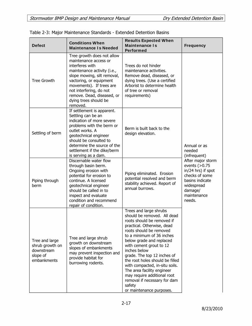
Stormwater BMP Design and Maintenance Manual Dry Extended Detention Basin
2-17 8/23/2010
Table 2-3: Major Maintenance Standards - Extended Detention Basins
Defect Conditions When Maintenance Is Needed
Results Expected When Maintenance Is Performed
Frequency
Tree Growth
Tree growth does not allow maintenance access or interferes with maintenance activity (i.e., slope mowing, silt removal, vactoring, or equipment movements). If trees are not interfering, do not remove. Dead, diseased, or dying trees should be removed.
Trees do not hinder maintenance activities. Remove dead, diseased, or dying trees. (Use a certified Arborist to determine health of tree or removal requirements)
Annual or as needed (infrequent) After major storm events (>0.75 in/24 hrs) if spot checks of some basins indicate widespread damage/ maintenance needs.
Settling of berm
If settlement is apparent. Settling can be an indication of more severe problems with the berm or outlet works. A geotechnical engineer should be consulted to determine the source of the settlement if the dike/berm is serving as a dam.
Berm is built back to the design elevation.
Piping through berm
Discernable water flow through basin berm. Ongoing erosion with potential for erosion to continue. A licensed geotechnical engineer should be called in to inspect and evaluate condition and recommend repair of condition.
Piping eliminated. Erosion potential resolved and berm stability achieved. Report of annual burrows.
Tree and large shrub growth on downstream slope of embankments
Tree and large shrub growth on downstream slopes of embankments may prevent inspection and provide habitat for burrowing rodents.
Trees and large shrubs should be removed. All dead roots should be removed if practical. Otherwise, dead roots should be removed to a minimum of 36 inches below grade and replaced with cement grout to 12 inches below grade. The top 12 inches of the root holes should be filled with compacted, in-situ soils. The area facility engineer may require additional root removal if necessary for dam safety or maintenance purposes.

Stormwater BMP Design and Maintenance Manual Dry Extended Detention Basin
2-18 8/23/2010
Defect Conditions When Maintenance Is Needed
Results Expected When Maintenance Is Performed
Frequency
Erosion on Spillway
Rock is missing and soil is exposed at top of spillway or outside slope.
Rocks and pad depth are restored to design standards.
Sediment accumulation
Sediment buildup exceeding 50% of the forebay sediment storage capacity. Six inches or more of accumulated sediment across basin bottom.
Basin capacity restored.
Standing water Low flow channel is not draining, standing pools of water are observed.
No standing pools of water in low flow channel.
Gate/Fence Damage
Damage to gate/fence, including missing locks and hinges
Gate/Fence repaired.

Stormwater BMP Design and Maintenance Manual Vegetated Swales
3-1 8/23/2010
3. VEGETATED SWALES
Definition
Vegetated swales are open, shallow channels with low-lying vegetation covering the side slopes and bottom that collect and slowly convey runoff flow to downstream discharge points. Vegetated swales provide pollutant removal through settling and filtration in the vegetation (usually grasses) lining the channels, provide the opportunity for stormwater volume reduction through infiltration and evapotranspiration, and reduce the flow velocity in addition to conveying stormwater runoff. An effective vegetated swale achieves uniform sheet flow over and through a densely vegetated area for a period of several minutes. The vegetation in the swale can vary depending on its location within a development project and is the choice of the designer, depending on the design criteria outlined below. Vegetated swales can be designed to be either on-line or off-line. On-line vegetated swales are used for conveying high flows as well as providing treatment of the water quality design flow, and can replace curbs, gutters, and storm drain systems. On-line swales are sized so that the low flow portion of the swale meets the treatment BMP design criteria, and the upper portion of the swale conveys high flows up to the capital storm (e.g. flood conveyance), with a set freeboard (per the LACFCD “Design Manual Hydraulics”). Flow velocities are limited to prevent reentrainment of sediment and associated pollutants. Off-line swales have flows up to the water quality design flow diverted to them from the conveyance system. Freeboard for off-line swales is 8 inches. The effectiveness of vegetated swales can be enhanced by adding check dams at approximately 50 foot increments along their length. These dams maximize the retention time within the swale, decrease flow velocities, and promote particulate settling. The incorporation of vegetated filter strips parallel to the top of the channel banks can help to treat sheet flows entering the swale.
General Constraints and Siting Considerations
• High flow velocity - steep terrain and/or large tributary area may cause erosive flows
• Shallow grades - limited site slope may cause ponding
• Compatibility with flood control - swales must not interfere with flood control functions of existing conveyance and detention structures
• Appropriate selection of vegetation based on irrigation requirements and exposure (shady versus sunny areas).
Multi-Use Opportunities
Swales can be easily integrated into roadside vegetated buffers or parking lot landscaping.

Stormwater BMP Design and Maintenance Manual Vegetated Swales
3-2 8/23/2010
Vegetated Swale Design Specifications
Geotechnical Considerations
Vegetated swales can be used wherever the local climate and soils permit the establishment and maintenance of an appropriate vegetative cover, and slopes are low or can be engineered to swale specifications. They are impractical in areas with steep topography (slopes in excess of approximately 10%).
Sizing
The flow capacity of a vegetated swale is a function of the longitudinal slope (parallel to flow), the resistance to flow (i.e. Manning’s roughness), and the cross sectional area. The cross section is normally approximately trapezoidal and the area is a function of the bottom width and side slopes. The flow capacity of vegetated swales should be such that the design water quality flow rate will not exceed a flow depth of 2/3 the height of the vegetation within the swale or 4 inches at the SUSMP design intensity. Once design criteria have been selected, the resulting flow depth for the design water quality flow rate is checked. If the depth restriction is exceeded, swale parameters (e.g. longitudinal slope, width) are adjusted to reduce the flow depth. Procedures for sizing swales are summarized below and illustrated in Figure 3-1.
Step 1: Select design flows
The swale sizing is based on the SUSMP design flow Qwq (see A Manual for the Standard Urban Storm Water Mitigation Plan, LACDPW, September 2002 (or as amended)).
Step 2: Calculate swale bottom width.
The swale bottom width is calculated based on Manning's equation for open-channel flow. This equation can be used to calculate discharges as follows:
5.067.1/49.1 SnARQ = (Equation 3-1) where:
Q = flow rate (cfs) n = Manning's roughness coefficient (unitless) A = cross-sectional area of flow (ft2) R = hydraulic radius (ft) = area divided by wetted perimeter S = longitudinal slope (ft/ft)
For shallow flow depths in swales, channel side slopes are ignored in the calculation of bottom width. Use the following equation (a simplified form of Manning's formula) to estimate the swale bottom width: 5.067.149.1/ synQb wqwq= (Equation 3-2)

Stormwater BMP Design and Maintenance Manual Vegetated Swales
3-3 8/23/2010
Where:
b = bottom width of swale (ft) Qwq = water quality design flow (cfs) nwq = Manning's roughness coefficient for shallow flow conditions = 0.2 (unitless) y = design flow depth (ft) s = longitudinal slope (along direction of flow) (ft/ft)
Proceed to Step 3 if the bottom width is calculated to be between 2 and 10 feet. A minimum 2-foot bottom width is required. Therefore, if the calculated bottom width is less than 2 feet, increase the width to 2 feet and recalculate the design flow depth y using the Equation 3-2 where Qwq, nwq, and s are the same values as used above, but b = 2 feet. The maximum allowable bottom width is 10 feet; therefore if the calculated bottom width exceeds 10 feet, then one of the following steps is necessary to reduce the design bottom width:
• Increase the longitudinal slope (s) to a maximum of 6 feet in 100 feet (0.06 feet per foot).
• Increase the design flow depth (y) to a maximum of 4 inches. • Place a divider lengthwise along the swale bottom (Figure 3-1) at least three-quarters of
the swale length (beginning at the inlet), without compromising the design flow depth and swale lateral slope requirements. Swale width can be increased to an absolute maximum of 16 feet if a divider is provided.
Step 3: Determine design flow velocity
To calculate the design flow velocity through the swale, use the flow continuity equation: wqwqwq AQV /= (Equation 3-3)
where:
Vwq = design flow velocity (fps) Awq = by + Zy2 = cross-sectional area (ft2) of flow at design depth, where Z = side
slope length per unit height (e.g., Z = 3 if side slopes are 3H:1V) If the design flow velocity exceeds 1 foot per second, go back to Step 2 and modify one or more of the design parameters (longitudinal slope, bottom width, or flow depth) to reduce the design flow velocity to 1 foot per second or less. If the design flow velocity is calculated to be less than 1 foot per second, proceed to Step 4. Note: It is desirable to have the design velocity as low as possible, both to improve treatment effectiveness and to reduce swale length requirements.

Stormwater BMP Design and Maintenance Manual Vegetated Swales
3-4 8/23/2010
Step 4: Calculate swale length
Use the following equation to determine the necessary swale length to achieve a hydraulic residence time of at least 10 minutes (600 seconds): wqhrVtL 60= (Equation 3-4)
Where:
L = minimum allowable swale length (ft) thr = hydraulic residence time (s) Vwq = design flow velocity (fps)
The minimum swale length is 100 feet; therefore, if the swale length is calculated to be less than 100 feet, increase the length to a minimum of 100 feet, leaving the bottom width unchanged. If a larger swale can be fitted on the site, consider using a greater length to increase the hydraulic residence time and improve the swale's pollutant removal capability. If the calculated length is too long for the site, or if it would cause layout problems, such as encroachment into shaded areas, proceed to Step 5 to further modify the layout. If the swale length can be accommodated on the site, proceed to Step 6.
Step 5: Adjust swale layout to fit on site
If the swale length calculated in Step 4 is too long for the site, the length can be reduced (to a minimum of 100 feet) by increasing the bottom width up to a maximum of 16 feet, as long as the 10 minute retention time is retained. However, the length cannot be increased in order to reduce the bottom width because Manning's depth-velocity-flow rate relationships would not be preserved. If the bottom width is increased to greater than 10 feet, a low flow dividing berm is needed to split the swale cross section in half to prevent channelization. Length can be adjusted by calculating the top area of the swale and providing an equivalent top area with the adjusted dimensions. a) Calculate the swale treatment top area based on the swale length calculated in Step 4: islopeitop LbbA )( += (Equation 3-5)
Where:
Atop = top area (ft2) at the design treatment depth bi = bottom width (ft) calculated in Step 2 bslope = the additional top width (ft) above the side slope for the design water depth (for
3:1 side slopes and a 4-inch water depth, bslope = 2 feet) Li = initial length (ft) calculated in Step 4.
b) Use the swale top area and a reduced swale length Lf to increase the bottom width, using
the following equation: )/( slopeftopf bbAL += (Equation 3-6)
where:

Stormwater BMP Design and Maintenance Manual Vegetated Swales
3-5 8/23/2010
Lf = reduced swale length (ft) bf = increased bottom width (ft).
c) Recalculate Vwq according to Step 3 using the revised cross-sectional area Awq based on the
increased bottom width bf. Revise the design as necessary if the design flow velocity exceeds 1 foot per second.
d) Recalculate to assure that the 10 minute retention time is retained.
Step 6: Provide conveyance capacity for flows higher than Qwq
Vegetated swales may be designed as flow-through channels that convey flows higher than the water quality design flow rate, or they may be designed to incorporate a high-flow bypass upstream of the swale inlet. A high-flow bypass usually results in a smaller swale size. If a high-flow bypass is provided, this step is not needed. If no high-flow bypass is provided, proceed with the procedure below. Flow diversion structure design is described in Appendix D. a) Check the swale size to determine whether the swale can convey the capital storm peak
flows (Refer to Design Manual - Hydraulic, Section C, “Criteria for Hydraulic Design Open Channels” and “Hydrology Manual” LACDPW).
b) The capital storm peak flow velocity must be less than 3.0 feet per second. If this velocity
exceeds 3.0 feet per second, return to Step 2 and increase the bottom width or flatten the longitudinal slope as necessary to reduce the capital storm peak flow velocity to 3.0 feet per second or less. If the longitudinal slope is flattened, the swale bottom width must be recalculated (Step 2) and must meet all design criteria.
Swale Geometry
1. In general, trapezoidal channel shape should be assumed for sizing calculations above, but a more naturalistic channel cross-section is preferred.
2. Swales designed for water quality treatment purposes only are anticipated to be fairly
shallow, generally less than 1-foot. Therefore, a side slope of 2:1 (H:V) can be used and is acceptable. Milder slopes are necessary for mowed turf swales (3H:1V max).
3. Overall depth from the top of the side walls to the swale bottom shall be at least 12 inches. 4. Swale length shall be greater than 100 linear feet. Regardless of the recommended
detention time, the swale should be not less than 100 feet in length. Length can be increased by meandering the swale.
5. The minimum swale bottom width shall be 2 feet to allow for ease of mowing. 6. The maximum swale bottom width shall be limited to 10 feet, unless a dividing berm is
provided, then maximum bottom width can be 16 feet. Swale width is calculated without the dividing berm. Intent: Experience shows that when the width exceeds about 10 feet, it

Stormwater BMP Design and Maintenance Manual Vegetated Swales
3-6 8/23/2010
is difficult to keep the water from concentrating in low-flow channels. It is also difficult to construct the bottom level and without sloping to one side. Vegetated swales are best constructed by leveling the bottom after excavating. A single-width pass with a front-end loader produces a better result than a multiple-width pass.
7. Swales that are required to convey flood as well as SUSMP flows should be sized to convey
the capital storm and include 2 feet of freeboard. 8. Gradual meandering bends in the swale are desirable for aesthetic purposes and to promote
slower flow.
Bottom Slope
1. The longitudinal slope (along the direction of flow) shall be between 1% and 6%. 2. If longitudinal slopes are less than 1.5% and the soils are poorly drained (e.g., silts and
clays), then underdrains shall be provided. A soils report to verify soils properties shall be provided for swales less than 1.5%.
3. If longitudinal slope exceeds 6%, check dams with vertical drops of 12 inches or less shall
be provided to achieve a bottom slope of 6% or less between the drop structures. 4. The lateral (horizontal) slope at the bottom of the swale shall be zero (flat) to discourage
channeling.
Water Depth and Dry Weather Flow Drain
1. Water depth should not exceed 4 inches (or 2/3 of expected vegetation height), except for frequently mowed turf swales, for which the depth should not exceed 2 inches.
2. The swale length must provide a minimum hydraulic residence time of 10 minutes. 3. A low flow drain shall be provided for dry weather flows extending the entire length of the
swale. The drain shall have a minimum depth of 6 inches, and a width no more than 5% of the calculated bottom swale width; the width of the drain shall be in addition to the required bottom width. If an anchored plate is used for flow spreading at the swale inlet, the plate wall shall have v-notches (maximum top width = 5% of swale width) or holes to allow preferential exit of low flows into the drain. If an underdrain is installed as required below, the low flow drain shall be omitted.
Energy Dissipation
1. Vegetated swales may be designed either on-line or off-line. If the facility is on-line, velocities shall be maintained below the maximum flow design velocity of 3 feet per second to prevent scour and resuspension of deposited sediments.
2. The maximum SUSMP flow velocity shall not exceed 1.0 foot per second. Intent: This
maximum SUSMP flow velocity promotes settling and keeps vegetation upright.

Stormwater BMP Design and Maintenance Manual Vegetated Swales
3-7 8/23/2010
3. This velocity limitation combined with a maximum depth of 4 inches and bottom width of 10 feet results in a recommended maximum flow capacity of about 3.3 cfs, after accounting for the side slopes. The contributory drainage area to each swale is limited so as not to exceed this recommended maximum flow capacity.
4. The maximum flow velocity during the capital storm shall not exceed 3.0 foot per second.
This can be accomplished by:
a. splitting roadside swales near high points in the road so that flows drain in opposite directions, mimicking flow patterns on the road surface.
b. limiting contributory drainage areas to long swales by diverting flows throughout the
length of the swale at regular intervals, to the downstream stormwater conveyance system.
5. A flow spreader (see “Flow Spreaders” below and detail in Figure 3-2) shall be used at the
inlet so that the entrance velocity is quickly dissipated and the flow is uniformly distributed across the whole swale. Energy dissipation controls shall be constructed of sound materials such as stones, concrete, or proprietary devices that are rated to withstand the energy of the influent flows.
6. If check dams are used to reduce the longitudinal slope, a flow spreader shall be provided
at the toe of each vertical drop, with specifications described below. 7. If flow is to be introduced through curb cuts, place pavement slightly above the elevation of
the vegetated areas. Curb cuts should be at least 12 inches wide to prevent clogging.
Flow Spreaders
1. An anchored plate flow spreader shall be provided at the inlet to the swale. Equivalent methods for spreading flows evenly throughout the width the swale are acceptable.
2. The top surface of the flow spreader plate shall be level, projecting a minimum of 2 inches
above the ground surface of the water quality facility, or v-notched with notches 6 to 10 inches on center and 1 to 4 inches deep (use shallower notches with closer spacing).
3. A flow spreader plate shall extend horizontally beyond the bottom width of the facility to
prevent water from eroding the side slope. The horizontal extent should be such that the bank is protected for all flows up to the capital design flow (on-line swales) or the maximum flow that will enter the WQ facility (off-line swales).
4. Flow spreader plates shall be securely fixed in place. 5. Flow spreader plates may be made of either concrete, stainless steel, or other durable
material. 6. Anchor posts shall be 4-inch square concrete, tubular stainless steel, or other material
resistant to decay.

Stormwater BMP Design and Maintenance Manual Vegetated Swales
3-8 8/23/2010
Check Dams
If check dams are required, they can be designed out of a number of different materials, including riprap, earthen berms, or removal stop logs. Check dams must be placed as to achieve the desired slope (<6%), and desired velocity (not to exceed 3 fps during the capital storm or 1 fps during the SUSMP storm), at a maximum of 50 feet apart. If rip rap is used, the material should consist of well-graded stone consisting of a mixture of rock sizes. The following is an example of an acceptable gradation:
Particle Size % Passing 24" 100 15" 75 9" 50 4" 10
Underdrains
If underdrains (not to be confused with a dry weather flow drain (see page 3-25 above)) are required, then they must meet the following criteria: 1. Underdrains must be made of slotted, polyvinyl chloride (PVC) pipe conforming to ASTM D
3034 or equivalent or corrugated high density polyethylene (HDPE) pipe conforming to AASHTO 252M or equivalent. Intent: As compared to round-hole perforated pipe, slotted underdrains provide greater intake capacity, clog resistant drainage, and reduced entrance velocity into the pipe, thereby reducing the chances of solids migration.
2. Slotted pipe shall have 2 to 4 rows of slots cut perpendicular to the axis of the pipe or at
right angles to the pitch of corrugations. Slots shall have a width of 0.04-inch to 0.1-inch and shall have a length of 1-inch to 1.25-inch. Slots shall be spaced such that the pipe has a minimum of one square inch per lineal foot.
3. The pipe must be 6 inches or greater in diameter, so it can be cleaned without damage to
the pipe. Clean-out risers with diameters equal to the underdrain pipe must be placed at the terminal ends of the underdrain and can be incorporated into the flow spreader and outlet structure to minimize maintenance obstacles in the swale. Intermediate clean-out risers may also be placed in the check dams or grade control structures. The cleanout risers shall be capped with a lockable screw cap.
4. The underdrain shall be placed parallel to the swale bottom and backfilled and bedded with
six inches of drain rock. The following aggregate shall be used to provide a gravel blanket and bedding for the underdrain pipe to provide a 1-foot minimum depth around the top and sides of the slotted pipe.
Sieve size Percent Passing ¾ inch 100 ¼ inch 30-60 US No. 8 20-50 US No. 50 3-12 US No. 200 0-1

Stormwater BMP Design and Maintenance Manual Vegetated Swales
3-9 8/23/2010
5. The drain rock must be wrapped in a geotextile fabric meeting the following minimum
materials requirements.
Geotextile Property Value Test MethodTrapezoidal Tear (lbs) 40 (min) ASTM D4533 Permeability (cm/sec) 0.2 (min) ASTM D4491 AOS (sieve size) #60 - #70 (min) ASTM D4751 Ultraviolet resistance 70% or greater ASTM D4355
6. The underdrain must infiltrate into the subsurface or drain freely to an acceptable discharge
point.
Swale Divider
1. If a swale divider is used, the divider should be constructed of a firm material that will resist weathering and not erode, such as concrete or compacted soil seeded with grass. Treated timber should not be used. Selection of divider material must take into account maintenance activities, such as mowing.
2. The divider must have a minimum height of 1 inch greater than the water quality design
water depth. 3. Earthen berms should be no steeper than 2H:1V. 4. Material other than earth shall be embedded to a depth sufficient to be stable.
Soils
1. Turf swale soils shall be amended with 2 inches of well-rotted compost, unless the organic content is already greater than 10%. The compost shall be mixed into the native soils to a depth of 6 inches to prevent soil layering and washout of compost. The compost will contain no sawdust, green or under-composted material, or any other toxic or harmful substance. It should contain no un-sterilized manure which can lead to high levels of pathogen indicators (coliform bacteria) in the runoff.
Vegetation
Swales must be vegetated in order to provide adequate treatment of runoff. It is important to maximize water contact with vegetation and the soil surface. 1. The swale area should be appropriately vegetated with a mix of erosion-resistant plant
species that effectively bind the soil. A diverse selection of low growing plants that thrive under the specific site, climatic, and watering conditions should be specified. A mixture of dry-area and wet-area grass species that can continue to grow through silt deposits is most effective. Native or adapted grasses are preferred because they generally require less fertilizer, limited maintenance, and are more drought resistant than exotic plants. Consultation with a landscape or erosion control specialist is recommended for project-

Stormwater BMP Design and Maintenance Manual Vegetated Swales
3-10 8/23/2010
specific recommendations on grass seed, fertilizer, and mulching applications to ensure healthy grass growth. Suitable plant types can also be found by referring to various online sources such as:
• CalFlora - a database of wild California plants that include plant characteristics and photos http://www.calflora.org
• The California Invasive Plant Council - a listing of invasive, non-native plants of California http://www.cal-ipc.org/
• L.A. River Master Plan Landscaping and Plant Palettes - a guidance document providing a listing of native plant communities in the Los Angeles area http://ladpw.org/wmd/watershed/LA/LAR_planting_guidelines_webversion.pdf
• Jepson Online Interchange For California Floristics - a database that provides information on identification, taxonomy, distribution, ecology, relationships, and diversity of California vascular plants. http://ucjeps.berkeley.edu/interchange.html
• VegSpec - a web-based decision support system that assists land managers in the planning and design of vegetative establishment practices http://ironwood.itc.nrcs.usda.gov/Netdynamics/Vegspec/pages/HomeVegspec.htm
• USDA Plants Database - an extensive database of native and non-native plants of the United States with over 100 plant characteristics http://plants.usda.gov/index.html
2. Trees or shrubs may be used in the surrounding landscape as long as they do not
excessively shade the swale. 3. Above the design treatment elevation, a typical lawn mix or landscape plants can be used
provided they do not shade the swale vegetation. 4. Irrigation is required if the seed is planted in spring or summer. Use of a permanent
irrigation system may help provide maximal water quality performance. Drought-tolerant grasses should be specified to minimize irrigation requirements.
5. Vegetative cover should be at least 4 inches in height, ideally 6 inches. Swale water depth
should ideally be 2 inches below the height of the shortest plant species and should not exceed 4 inches.
6. Locate the swale in an area without excessive shade to avoid poor vegetative growth. For
moderately shaded areas, shade tolerant plants should be used. 7. Locate the swale away from large trees that may drop leaves or needles. Excessive tree
debris may smother the grass or impede the flow through the swale. Landscape planter beds should be designed and located so that soil does not erode from the beds and enter a nearby swale.

Stormwater BMP Design and Maintenance Manual Vegetated Swales
3-11 8/23/2010
Restricted Construction Materials
The use of treated wood or galvanized metal within the vegetated swale is prohibited.


Stormwater BMP Design and Maintenance Manual Vegetated Swales
3-14 8/23/2010
Vegetated Swale Maintenance Standards
General Requirements
1. Inspect vegetated swales for erosion or damage to vegetation after every storm greater
than 0.75" for on-line swales and at least twice annually for off-line swales, preferably at the end of the wet season to schedule summer maintenance and in the fall to ensure readiness for winter (see Appendix E for guidance on facility inspection). Additional inspection after periods of heavy runoff is recommended. Each swale should be checked for debris and litter and areas of sediment accumulation (see Appendix F for a vegetated swale inspection and maintenance checklist).
2. Swale inlets (curb cuts or pipes) should maintain a calm flow of water entering the swale.
Remove sediment as needed at the inlet if vegetation growth is inhibited in greater than 10% of the swale or if the sediment is blocking even distribution and entry of the water. Following sediment removal activities, replanting and/or reseeding of vegetation may be required for reestablishment.
3. Flow spreaders should provide even dispersion of flows across the swale. Sediments and
debris should be removed from the flow spreader if blocking flows. Splash pads should be repaired if needed to prevent erosion. Spreader level should be checked and releveled if necessary.
4. Side slopes should be maintained to prevent erosion that introduces sediment into the
swale. Slopes should be stabilized and planted using appropriate erosion control measures when native soil is exposed or erosion channels are forming.
5. Swales should drain within 48 hours of the end of a storm. Till the swale if compaction or
clogging occurs and revegetate. The perforated underdrain pipe, if present, should be cleaned if necessary.
6. Vegetation should be healthy and dense enough to provide filtering while protecting
underlying soils from erosion:
• Mulch should be replenished as needed to ensure survival of vegetation. • Vegetation, large shrubs or trees that interfere with landscape swale operation should
be pruned. • Fallen leaves and debris from deciduous plant foliage should be removed. • Grassy swales should be mowed to keep grass 4” to 6” in height. Grass clippings shall
be removed. • Invasive vegetation, such as Alligatorweed (Alternanthera philoxeroides), Halogeton
(Halogeton glomeratus), Spotted Knapweed (Centaurea maculosa), Giant Reed (Arundo donax), Castor Bean (Ricinus communis), Perennial Pepperweed (Lepidium latifolium), and Yellow Starthistle (Centaurea solstitalis) must be removed and replaced with non-invasive species. Invasive species should never contribute more than 10% of the vegetated area. For more information on invasive weeds, including biology and control

Stormwater BMP Design and Maintenance Manual Vegetated Swales
3-15 8/23/2010
of listed weeds, look at the “encycloweedia” located at the California Department of Food and Agriculture website at http://www.cdfa.ca.gov/wma or the California Invasive Plant Council website at http://portal.cal-ipc.org/weedlist.
• Dead vegetation should be removed if greater than 10% of area coverage or when swale function is impaired. Vegetation should be replaced and established before the wet season to maintain cover density and control erosion where soils are exposed.
7. Check dams (if present) should control and distribute flow across the swale. Causes for
altered water flow and/or channelization should be identified and obstructions cleared. Check dams and swale should be repaired if damaged.
8. The vegetated swale should be well maintained; trash and debris, sediment, visual
contamination (e.g., oils), noxious or nuisance weeds, should all be removed.
Maintenance Standards
A summary of the routine and major maintenance activities recommended for vegetated swales is shown in Table 3-1. Detailed routine and major maintenance standards are listed in Tables 3-2 and 3-3.
Table 3-1: Vegetated Swale Routine and Major Maintenance Quick Guide
Inspection and Maintenance Activities Summary
Rou
tin
e M
ain
ten
ance
• Remove excess sediment as needed • Removal trash and debris • Clean underdrain (where applicable) and/or unclog outlet to eliminate standing water • Clean and reset flow spreaders as needed to restore original function • Restore sunlight access to shaded regions. Remove overhanging tree branches as
needed to prevent excessive shading. • Remove any evidence of visual contamination from floatables such as oil and grease • Mow routinely to maintain ideal grass height and to suppress weeds • Replace invasive vegetation with non-invasive species • Remove sediment and debris accumulation near inlet and outlet structures • Stabilize/repair minor erosion and scouring with gravel • Take photographs before and after maintenance (encouraged)
Maj
or M
ain
ten
ance
• Regrade swale bottom and reseed to mitigate ponding of water between storms or excessive erosion and scouring
• Install or replace low flow channel using pea gravel media to better convey nuisance flows
• Revegetate bare exposed portions of the swale to restore vegetation to original level of coverage
• De-thatch grass to remove accumulated sediment and aerate compacted areas to promote infiltration

Stormwater BMP Design and Maintenance Manual Vegetated Swales
3-16 8/23/2010
Table 3-2: Routine Maintenance Standards - Vegetated Swales
Defect or Problem
Condition When Maintenance is Needed
Results Expected When Maintenance Is Performed
Frequency
Sediment Accumulation
Sediment depth exceeds 2 inches or covers vegetation.
Sediment deposits on grass treatment area of the vegetated swale removed without significant disturbance of the vegetation. When finished, swale should be level from side to side and drain freely toward outlet. There should be no areas of standing water once inflow has ceased.
Annually prior to wet season After major storm events (>0.75 in/24 hrs) if spot checks of some basins indicate widespread damage/ maintenance needs
Trash and Debris Accumulation
Any trash and debris which exceed 5 cubic feet per 1,000 square feet (one standard garbage can).
Trash and debris removed from vegetated swale.
Standing Water When water stands in the swale between storms and does not drain freely.
There should be no areas of standing water once inflow has ceased. Outlet structures and underdrain (if installed) shall drain freely.
Flow Spreader
Flow spreader uneven or clogged so that flows are not uniformly distributed through entire swale width.
Spreader leveled and cleaned such that flows are distributed evenly over entire swale width.
Excessive Shading
Vegetation growth is poor because sunlight does not reach swale.
Over-hanging limbs and brushy vegetation on side slopes are trimmed back.
Erosion/ Scouring
Eroded or scoured swale bottom due to flow channelization or higher flows.
No erosion or scouring in swale bottom. For ruts or bare areas less than 12 inches wide, damaged areas repaired by filling with crushed gravel. Over time, the grass will have started to cover the rock.
Visual Contaminants and Pollution
Any visual evidence of oil, gasoline, contaminants or other pollutants.
No visual contaminants or pollutants present.
Vegetation Length
When the grass becomes excessively tall (greater than 10-inches); when nuisance weeds and other vegetation starts to take over.
Vegetation mowed or nuisance vegetation removed so that flow is not impeded. Grass should be mowed to a height of 4 to 6 inches (depending on landscape requirements). Grass clippings removed.
Monthly (or as dictated by agreement between County and landscape contractor

Stormwater BMP Design and Maintenance Manual Vegetated Swales
3-17 8/23/2010
Defect or Problem
Condition When Maintenance is Needed
Results Expected When Maintenance Is Performed
Frequency
Inlet/Outlet Blockage
Inlet/outlet areas clogged with sediment and/or debris.
Material removed so that there is no clogging or blockage in the inlet and outlet area.
Low Flow Channel Overflow
Nuisance flows are ponding, swale is continually wet.
Low flow channel media is renewed to adequately convey nuisance flows.
Table 3-3: Major Maintenance Standards - Vegetated Swales
Defect or Problem
Condition When Maintenance is Needed
Results Expected When Maintenance Is Performed
Frequency
Standing Water When water stands in the swale between storms and does not drain freely.
There should be no areas of standing water once inflow has ceased. Any of the following may apply: improved grade from head to foot of swale, removed clogged check dams, added underdrains or converted to a wet biofiltration swale.
Annual – preferably at end of wet season or as needed (infrequent) After major storm events (>0.75 in/24 hrs) if spot checks of some basins indicate widespread damage/ maintenance needs
Erosion/ Scouring
Eroded or scoured swale bottom due to flow channelization, or higher flows.
No erosion or scouring in swale bottom. Bare areas greater than 12 inches wide are regraded and reseeded.
Constant Baseflow
When small quantities of water continually flow through the swale, even when it has been dry for weeks and an eroded, muddy channel has formed in the swale bottom
No eroded, muddy channel on the bottom. A low-flow pea-gravel drain added to the length of the swale, or an underdrain installed.
Poor Vegetation Coverage
When grass is sparse or bare or eroded patches occur in more than 10% of the swale bottom.
Vegetation coverage in more than 90% of the swale bottom. Poorly vegetated areas are replanted with plugs of grass from the upper slope and reseeded there, plugs planted in the swale bottom with no gaps, or reseeded into loosened, fertile soil.
Semiannual – at beginning and end of wet season

Stormwater BMP Design and Maintenance Manual Filter Strips
4-1 8/23/2010
4. FILTER STRIPS
Definition
Filter strips are vegetated areas designed to treat sheet flow runoff from adjacent impervious surfaces or intensive landscaped areas such as golf courses. Filter strips decrease runoff velocity, filter out TSS and associated pollutants, and provide some infiltration into underlying soils. While some assimilation of dissolved constituents may occur, filter strips are generally more effective in trapping sediment and particulate-bound metals, nutrients, and pesticides. Nutrients that bind to sediment include phosphorus and ammonium; soluble nutrients include nitrate. Filter strips are more effective when the runoff passes through the vegetation and thatch layer in the form of shallow, uniform flow. Biological and chemical processes may help break down pesticides, uptake metals, and utilize nutrients that are trapped in the filter. Filter strips rely on dense turf vegetation with a thick thatch, growing on a moderately permeable soil and are well suited to treat runoff from roads and highways, driveways, roof downspouts, small parking lots, and other impervious surfaces. They are also good for use as vegetated buffers between developed areas and natural drainages.
General Constraints and Siting Considerations
• High flow velocity - steep terrain and/or large tributary area may cause concentrated, erosive flows
• Sheet flow - shallow, evenly-distributed flow across entire width of strip required. The maximum flow path from a contributory impervious surface should not exceed 150 feet.
• Shallow grades - limited site slope may cause ponding
• Availability of pervious area adjacent to impervious area - filter strips require sheet flow from impervious areas
Multi-Use Opportunities
Filter strips can be easily integrated into roadside vegetated buffers or parking lot landscaping.
Filter Strip Design Specifications
The main challenge associated with filter strips is maintaining sheet flow, which is critical to performance of this BMP. If flows are concentrated then little or no treatment of stormwater runoff is achieved and erosive rilling is likely. The use of a level spreading device (e.g., gravel trench) to deliver shallow, evenly-distributed sheet flow to the strip is required. A filter strip is illustrated schematically in Figure 4-1.
Location
1. The use of filter strips is limited to gently sloping areas where the vegetative cover is robust and diffuse, and where shallow flow characteristics are possible.

Stormwater BMP Design and Maintenance Manual Filter Strips
4-2 8/23/2010
2. The filter strip shall be located away from building or tree shadows to avoid poor plant growth.
3. Groundwater levels should be at least 2 ft lower than the strip surface to ensure that the
filter strip does not remain wet between storms.
Tributary Area Length
1. Maximum length (in the direction of flow towards the filter strip) of the tributary area shall be 150 feet.
2. The lateral slope of the contributing area (parallel to the edge of the pavement) shall be 4%
or less. 3. The longitudinal slope of the contributing area (parallel to the flow) should be 5% or less.
Sizing
Step 1: Calculate the design flow
The design flow is calculated as described in A Manual for the Standard Urban Storm Water Mitigation Plan, LACDPW, September 2002 (or as amended).
Step 2: Calculate the design flow depth
The design flow depth (d) is calculated based on the width and the slope (parallel to the flow path) using a modified Manning’s equation as follows: 6.05.0 ]49.1/[ WsnQd wqwqf = (Equation 4-1)
where: df = design flow depth (ft) Qwq = design flow (cfs)
W = width (perpendicular to flow = width of impervious surface contributing area (ft) s = slope (ft/ft) of strip parallel to flow, average over the whole width nwq = Manning’s roughness coefficient (0.25-0.3)
If df is greater than 1 inch, then a smaller slope is required, or a filter strip cannot be used.
Step 3: Calculate the design velocity
The design flow velocity is based on the design flow, design flow depth, and width of the strip: WdQV fwqwq /= (Equation 4-2)

Stormwater BMP Design and Maintenance Manual Filter Strips
4-3 8/23/2010
Step 4: Calculate the desired length of the filter strip
Determine the required length (L) to achieve a desired minimum residence time of 10 minutes using: wqhrVtL 60= (Equation 4-3)
Where:
L = minimum allowable strip length (ft) thr = hydraulic residence time (s) Vwq = design flow velocity (fps)
Geometry
1. The width of the filter strip vegetative surface should extend across the full width of the tributary area. The upstream boundary of the filter should be located contiguous to the developed area.
2. The filter strip should be at least 4 feet long (in direction of flow) to provide adequate water
quality treatment. 3. Filter strips should be designed on slopes (parallel to the direction of flow) between 2% and
15%; steeper slopes tend to result in concentrated flow. Slopes less than 2% could pond runoff, and in poorly permeable soils, create a mosquito breeding habitat.
4. The lateral slope of strip (parallel to the edge of the pavement, perpendicular to the
direction of flow) shall be 4% or less. 5. Grading should be even: a filter strip with uneven grading perpendicular to the flow path
will develop flow channels over time. 6. The top of the strip should be installed 2 to 5 inches below the adjacent pavement to allow
for vegetation and sediment accumulation at the edge of the strip. A beveled transition is acceptable and may be required per roadside design specifications.
7. Both the top and toe of the slope should be as flat as possible to encourage sheet flow and
prevent channeling and erosion. For engineered vegetative strips, the facility surface should be graded flat prior to placement of vegetation.
Energy Dissipation / Level Spreading
Runoff entering a filter strip must not be concentrated. A flow spreader shall be installed at the edge of the pavement to uniformly distribute the flow along the entire width of the filter strip. 1. At a minimum, a gravel flow spreader (gravel-filled trench) shall be placed between the
impervious area contributing flows and the filter strip, and meet the following requirements:
a) The gravel flow spreader shall be a minimum of 6 inches deep and shall be 12 inches wide.

Stormwater BMP Design and Maintenance Manual Filter Strips
4-4 8/23/2010
b) The gravel shall be a minimum of 1 inch below the pavement surface. Intent: This
allows sediment from the paved surface to be accommodated without blocking drainage onto the strip.
c) Where the ground surface is not level, the gravel spreader must be installed so that the
bottom of the gravel trench and the outlet lip are level. d) Along roadways, gravel flow spreaders must be placed and designed in accordance with
County road design specifications for compacted road shoulders. 2. A notched curb spreader and through-curb port spreader may only be used in conjunction
with a gravel spreader to better ensure that water sheet-flows onto the strip, provided:
a. Curb ports use fabricated openings that allow concrete curbing to be poured or extruded while still providing an opening through the curb to admit water to the filter strip. Openings in the curb shall be at regular intervals but at least every 6 feet. The width of each curb port opening shall be a minimum of 11 inches. Approximately 15 percent or more of the curb section length should be in open ports, and no port should discharge more than about 10 percent of the flow.
b. Interrupted curbs are sections of curb placed to have gaps spaced at regular intervals
along the total width of the treatment area. At a minimum, gaps shall be every 6 feet to allow distribution of flows into the treatment facility before they become too concentrated. The opening shall be a minimum of 11 inches. As a general rule, no opening should discharge more than 10 percent of the overall flow entering the facility.
3. Energy dissipaters are needed in a filter strip if sudden slope drops occur, such as locations
where flows in a filter strip pass over a rockery or retaining wall aligned perpendicular to the direction of flow. Adequate energy dissipation at the base of a drop section can be provided by a riprap pad.
Access
Access shall be provided at the upper edge of a filter strip to enable maintenance of the inflow spreader throughout the strip width and allow access for mowing equipment.
Water depth and Velocity
1. The design water depth should not exceed 1 inch. 2. Runoff flow velocities should not exceed approximately 1 foot per second across the
vegetated surface.
Soils
1. Filter strip soils shall be amended with 2 inches of well-rotted compost, unless the organic content is already greater than 10%. The compost shall be mixed into the native soils to a depth of 6 inches to prevent soil layering and washout of compost. The compost will contain no sawdust, green or under-composted material, or any other toxic or harmful

Stormwater BMP Design and Maintenance Manual Filter Strips
4-5 8/23/2010
substance. It should contain no un-sterilized manure which can lead to high levels of pathogen indictors (coliform bacteria) in the runoff.
Vegetation
1. The filter area should be densely vegetated with a mix of erosion-resistant plant species that effectively bind the soil. Native or adapted grasses are preferred because they generally require less fertilizer and are more drought resistant than exotic plants.
2. Sod can be used instead of grass seed, as long as there is complete coverage. 3. Irrigation shall be provided to establish the grass.
Trees or shrubs shall not be used because they shade the turf.
Restricted Construction Materials
The use of treated wood or galvanized metal anywhere inside the facility is prohibited.


Stormwater BMP Design and Maintenance Manual Filter Strips
4-7 8/23/2010
Filter Strip Operations and Maintenance
General Requirements
Filter strips mainly require vegetation management; therefore little special training is needed for maintenance crews. Typical maintenance activities and frequencies include: 1. Inspect strips at least twice annually for erosion or damage to vegetation, preferably at the
end of the wet season to schedule summer maintenance and in the fall to ensure the strip is ready for winter (see Appendix E for guidance on facility inspection). However, additional inspection after periods of heavy runoff is most desirable. The strip should be checked for debris and litter and areas of sediment accumulation (see Appendix F for dry extended detention basin inspection and maintenance checklist).
2. Mow as frequently as necessary (at least twice a year) for safety and aesthetics or to
suppress weeds and woody vegetation. 3. Trash tends to accumulate in strip areas, particularly along roadways. The need for litter
removal should be determined through periodic inspection. Litter should always be removed prior to mowing.
4. Regularly inspect vegetated buffer strips for pools of standing water. Vegetated filter strips
can become a nuisance due to mosquito breeding in level spreaders (unless designed to dewater completely in less than 72 hours), in pools of standing water if obstructions develop (e.g. debris accumulation, invasive vegetation), and/or if proper drainage slopes are not implemented and maintained.
5. Activities that lead to ruts or depressions on the surface of the filter strip shall be prevented
or the integrity of the strip shall be restored by leveling and reseeding. Examples are vehicle tracks, utility maintenance, and pedestrian (short-cut) tracks.
Maintenance Standards
A summary of the routine and major maintenance activities recommended for filter strips is shown in Table 4-1. Detailed Routine and major maintenance standards are listed in Tables 4-2 and 4-3.

Stormwater BMP Design and Maintenance Manual Filter Strips
4-8 8/23/2010
Table 4-1: Filter Strip Routine and Major Maintenance Quick Guide
Inspection and Maintenance Activities Summary
Rou
tin
e M
ain
ten
ance
• Remove excess sediment as needed • Stabilize/repair minor erosion and scouring with crushed gravel • Remove trash and debris • Remove any evidence of visual contamination from floatables such as oil and grease • Mow routinely to maintain ideal grass height and to suppress weeds • Remove invasive vegetation and revegetate with non-invasive species • Take photographs before and after maintenance (encouraged)
Maj
or M
ain
ten
ance
• Regrade and revegetate to repair damage from severe erosion/scour channelization and to restore sheet flow
• Clean and reset flow spreaders as needed to restore original function
Table 4-2: Routine Maintenance – Filter Strips
Defect Conditions When Maintenance Is Needed
Results Expected When Maintenance Is Performed Frequency
Sediment Accumulation
Sediment depth exceeds 2 inches or covers vegetation.
Sediment deposits removed, releveled so slope is even and flows pass evenly through strip. Semi-annually,
prior to wet season and after the wet season After major storm events (>0.75 in/24 hrs) if spot checks indicate widespread damage/ maintenance needs
Erosion/Scouring Eroded or scoured areas due to flow channelization, or higher flows.
No erosion or scouring evident. For ruts or bare areas less than 12 inches wide, damaged areas repaired by filling with crushed gravel. The grass will creep in over the rock in time.
Flow Spreader Clogged/Uneven
Flow spreader uneven or clogged so that flows are not uniformly distributed through entire filter width.
Spreader leveled and cleaned so that flows are spread evenly over entire filter width.
Visual Contaminants and Pollution
Any visual evidence of oil, gasoline, contaminants or other pollutants.
No visual contaminants or pollutants present.

Stormwater BMP Design and Maintenance Manual Filter Strips
4-9 8/23/2010
Defect Conditions When Maintenance Is Needed
Results Expected When Maintenance Is Performed Frequency
Aesthetics Minor vegetation removal and thinning. Mowing berms and surroundings
Facility is well kept. Semi-annually (or as dictated by agreement between County and landscape contractor) Litter removal and mowing frequency is dependent on site conditions and desired aesthetics and should be done at a frequency to meet those objectives
Vegetation Length, Nuisance Weeds
When the grass becomes excessively tall (greater than 10-inches); when nuisance weeds and other vegetation starts to take over.
Grass mowed, nuisance vegetation controlled, such that flow is not impeded. Grass mowed to a height between 2-4 inches and clippings removed.
Trash and Debris Accumulation
Trash and debris accumulated on the filter strip.
Trash and debris removed from filter.
Noxious Weeds Any evidence of noxious weeds.
All noxious weeds eradicated and future establishment controlled with use of Integrated Pest Management (IPM) techniques, if applicable. See http://www.ipm.ucdavis.edu/ for more information.
Table 4-3: Major Maintenance – Filter Strips
Defect Conditions When Maintenance Is Needed
Results Expected When Maintenance Is Performed Frequency
Erosion/Scouring Bare spots greater than 12 inches
No erosion visible. Large, bare areas greater than 12 inches wide regraded and reseeded.
As needed

Stormwater BMP Design and Maintenance Manual Bioretention
5-1 8/23/2010
5. BIORETENTION
Definition
Bioretention areas are vegetated (i.e., landscaped) shallow depressions that provide storage, infiltration, and evapotranspiration. Bioretention areas also remove pollutants by filtering stormwater through plants adapted to the local climate and soil moisture conditions and an engineered soil mix. In bioretention areas, pore spaces, microbes, and organic material in the engineered soils help to retain water in the form of soil moisture and to promote the adsorption of pollutants (e.g., dissolved metals and petroleum hydrocarbons) into the soil matrix. Plants utilize soil moisture and promote the drying of the soil through transpiration. If no underdrain is provided, exfiltration of the stored water in the bioretention area engineered soil into the underlying soils occurs over a period of days. For areas with low permeability native soils or steep slopes, bioretention areas can be designed with an underdrain system that routes the treated runoff to the storm drain system rather than depending on infiltration. In this situation, treatment is achieved mainly through filtration and adsorption in the vegetation and engineered soils in the biofiltration area.
General Constraints and Siting Considerations
• Native soil infiltration rate - underdrain is required in low permeability soils
• Vertical relief and proximity to storm drain - site must have adequate relief between land surface and storm drain to permit vertical percolation through the soil media and collection and conveyance in underdrain to storm drain system
• Depth to groundwater - shallow groundwater table may not permit complete drawdown between storms
Multi-Use Opportunities
Bioretention areas can be applied in various settings, including:
• Individual lots for rooftop, driveway, and other on-lot impervious surface infiltration. • Shared facilities located in common areas for individual lots. • Areas within loop roads or cul-de-sacs. • Landscaped parking lot islands. • Within right-of-ways along roads. • Common landscaped areas in apartment complexes or other multifamily housing
designs. • In parks and along open space edges.
Bioretention Design Specifications
Geotechnical and Landscape Considerations
1. Bioretention areas located within 50 feet of a sensitive steep slope shall incorporate an underdrain. A geotechnical report must be provided to address the potential effects of

Stormwater BMP Design and Maintenance Manual Bioretention
5-2 8/23/2010
infiltration on the steep slope if a bioretention area without an underdrain is sited within 200 feet of the slope or hazardous landslide area.
2. An underdrain should be provided for the bioretention area when native soils permeability is
less than 0.5 inches/hour, as determined by an in-situ percolation test.
Pretreatment
1. Bioretention areas shall use a filter strip to pretreat and spread incoming flows from roadways. Bioretention areas that treat runoff from residential roofs, sidewalks, driveways, or other “cleaner” surfaces do not require pretreatment.
2. If sheet flow is conveyed to the treatment area over stabilized grassed areas, the site must
be graded in such a way that minimizes erosive conditions. Sheet flow velocities shall not exceed 1 foot per second.
Sizing Criteria
Bioretention areas can be sized using one of two methods: a simple sizing method or a routing method. The simple sizing procedure is summarized below. Continuous simulation modeling, routing spreadsheets, and/or other forms of routing modeling that incorporate rainfall-runoff relationships and infiltrative (flow) capacities of bioretention may be used to size facilities. Alternative sizing methodologies should be prepared with good engineering practices. For the routing modeling method, refer to Section 10 - Sand Filters. A bioretention sizing worksheet and example are provided in Appendix B.
With either method, the runoff entering the facility must completely drain the ponding area and the planting soil within 48 hours. Bioretention provides storage above ground, in the voids of the planting soil, and (if used) in the voids of gravel drainage layer. Bioretention is to be sized, with or without underdrains, such that the SUSMP volume will fill the available ponding depth, the void spaces in the planting soil, and (if provided) the gravel drainage layer. Step 1: Calculate the design volume Bioretention areas should be sized to capture and treat the SUSMP volume (see A Manual for the Standard Urban Storm Water Mitigation Plan, LACDPW, September 2002 (or as amended)).
Step 2: Determine the design percolation rate
The design percolation rate, Pdesign, will differ depending on whether the native soil percolation rate falls above or below a rate of 0.5 in/hr. Sites where the native soil percolation rate is equal to or exceeds 0.5 in/hr, measured per the Policy for New Percolation Basin Testing, Design, and Maintenance (see Appendix G), do not require the use of an underdrain, while sites where native soil percolation rates are less than 0.5 in/hr require the use of an underdrain.

Stormwater BMP Design and Maintenance Manual Bioretention
5-3 8/23/2010
Option 1: Determining the design percolation rate, Pdesign, with an underdrain If the bioretention includes an underdrain, then the design percolation rate will be that of the planting soil. The planting soil design specifications listed below are assumed to have a design percolation rate of 2.5 in/hr. Option 2: Determining the design percolation rate, Pdesign, of the native subsoil (no underdrain) If the bioretention area does not include an underdrain, then the design percolation rate will be the limiting percolation rate (slowest) of the native subsoil, using in-situ tests described in Appendix G, and the planting soil. In most cases, the limiting percolation rate will be that of the native subsoil. It is important that adequate conservatism is incorporated in the selection of design percolation rates. The design percolation rate discussed here is the percolation rate of the underlying subsoil and not the percolation rate of the planting soil.
The design percolation rate may be calculated by applying correction factors to the field-measured percolation rate. A percolation testing correction factor applied to bioretention sizing of 0.25 (providing a safety factor of 4) should be applied to results of the percolation testing conducted per Appendix G.
Pdesign = Pmeasured x Ftesting (Equation 5-1)
Where:
Pdesign = design percolation rate (in/hr)
Pmeasured = field measured percolation rate (in/hr) Ftesting = correction factor for testing method; use 0.25
Step 3: Calculate the bioretention surface area
Determine the bottom surface area of the bioretention (surface area at the base of sideslopes, not at the top of sideslopes) using the following equation:
l))(d(t)(P)(l)(V
design
designA +=12/ (Equation 5-2)
Where: Vdesign = SUSMP volume (ft3) Pdesign = design percolation rate (in/hr) d = ponding depth (ft) [max 1.5 ft] l = depth of planting media (ft) [min 2 ft] t = required drawdown time (hr) [max 48 hrs]

Stormwater BMP Design and Maintenance Manual Bioretention
5-4 8/23/2010
Gravel Drainage Layer. A gravel drainage layer should be provided where underlying native soil permeability is greater than 0.5 in/hr and percolation is allowed. The base of the drainage layer should have zero slope (level). The drawdown time for the gravel drainage layer should not exceed 72 hours. The planting soil and gravel layers should be separated with a thin, 2- to 4-inch layer of sand and a thin layer (nominally two inches) of #8 stone. Determine the maximum depth of runoff that can be infiltrated within the required drain time (72 hr) as follows:
tPdesignd ∗= 12max (Equation 5-3)
Where:
dmax = the maximum depth of water that can be infiltrated within the required drain time (ft)
Pdesign = native subsoil design percolation rate (in/hr) [measured percolation rate x 0.25] t = required drain time (hrs) [72 hours]
Choose the gravel drainage layer depth (l) such that:
lnd ∗≥max (Equation 5-4)
Where:
dmax = the maximum depth of water that can be infiltrated within the required drain time (ft)
n = gravel drainage layer porosity (unitless) l = depth of gravel drainage layer (ft)
Calculate the infiltrating surface area (filter bottom area) required:
nlTPdesign
designVA
+=
12 (Equation 5-5)
Where:
Vdesign = SUSMP volume (ft3) n = gravel drainage layer porosity (unitless) Pdesign = native subsoil design percolation rate (in/hr) [measured percolation rate x 0.25] l = depth of gravel drainage layer (ft) T = fill time (time to fill bioretention area with water) (hrs) [use 2 hours for most
designs] A = surface area of gravel drainage layer (ft2)

Stormwater BMP Design and Maintenance Manual Bioretention
5-5 8/23/2010
Geometry
1. Bioretention areas shall be sized to capture and treat the SUSMP volume (see A Manual for the Standard Urban Storm Water Mitigation Plan, LACDPW, September 2002 (or as amended)) with an 18-inch maximum ponding depth.
2. Planting soil depth shall be a minimum of 2 feet, although 3 feet is preferred. Intent: The
planting soil depth should provide a beneficial root zone for the chosen plant palette and adequate water storage for the water quality design volume. A deeper planting soil depth will provide a smaller surface area footprint.
3. Bioretention areas shall be designed to drain in less than 48 hours. Intent: Soils must be
allowed to dry out periodically in order to restore hydraulic capacity to receive flows from subsequent storms, maintain percolation rates, maintain adequate soil oxygen levels for healthy soil biota and vegetation, and to provide proper soil conditions for biodegradation and retention of pollutants.
Flow Entrance and Energy Dissipation
The following types of flow entrance can be used for bioretention cells: 1. Dispersed, low velocity flow across a landscape area. Dispersed flow may not be possible
given space limitations or if the facility is controlling roadway or parking lot flows where curbs are mandatory.
2. Dispersed flow across pavement or gravel and past wheel stops for parking areas. 3. Flow spreading trench around perimeter of bioretention area. May be filled with pea gravel
or vegetated with 3:1 side slopes similar to a swale. A vertical-walled open trench may also be used at the discretion of the County.
4. Curb cuts for roadside or parking lot areas: curb cuts should include rock or other erosion
protection material in the channel entrance to dissipate energy. Flow entrance should drop 2 to 3 inches from curb line and provide an area for settling and periodic removal of sediment and coarse material before flow dissipates to the remainder of the cell.
5. Pipe flow entrance: Piped entrances, such as roof downspouts, should include rock, splash
blocks, or other erosion protection material at the entrance to dissipate energy and disperse flows.
6. Woody plants (trees, shrubs, etc.) can restrict or concentrate flows and can be damaged by
erosion around the root ball and shall not be placed directly in the entrance flow path.
Underdrains
If underdrains are required, then they must meet the following criteria: 1. 6-inch minimum diameter.

Stormwater BMP Design and Maintenance Manual Bioretention
5-6 8/23/2010
2. Underdrains must be made of slotted, polyvinyl chloride (PVC) pipe (PVC SDR 35 or approved equivalent). Intent: As compared to round-hole perforated pipe, slotted underdrains provide greater intake capacity, clog resistant drainage, and reduced entrance velocity into the pipe, thereby reducing the chances of solids migration.
3. Slotted pipe shall have 2 to 4 rows of slots cut perpendicular to the axis of the pipe or at
right angles to the pitch of corrugations. Slots shall be 0.04 to 0.1-inch and shall have a length of 1-inch to 1.25-inch. Slots shall be longitudinally spaced such that the pipe has a minimum of one square inch per lineal foot.
4. Underdrains shall be sloped at a minimum of 0.5%. 5. Rigid non-perforated observation pipes with a diameter equal to the underdrain diameter
shall be connected to the underdrain every 250 to 300 feet to provide a clean-out port as well as an observation well to monitor dewatering rates. The wells/cleanouts shall be connected to the perforated underdrain with the appropriate manufactured connections. The wells/cleanouts shall extend 6 inches above the top elevation of the bioretention facility mulch, and shall be capped with a lockable screw cap. The ends of underdrain pipes not terminating in an observation well/cleanout shall also be capped.
6. The following aggregate shall be used to provide a gravel blanket and bedding for the
underdrain pipe. Place the underdrain on a bed of washed aggregate at a minimum thickness of 6 inches and cover with the same aggregate to provide a 1-foot minimum depth around the top and sides of the slotted pipe.
Sieve size Percent Passing ¾ inch 100 ¼ inch 30-60 US No. 8 20-50 US No. 50 3-12 US No. 200 0-1
7. At the option of the designer/geotechnical engineer, a geotextile fabric may be placed
between the planting media and the drain rock. If a geotextile fabric is used it must meet the following minimum materials requirements.
Geotextile Property Value Test MethodTrapezoidal Tear (lbs) 40 (min) ASTM D4533 Permeability (cm/sec) 0.2 (min) ASTM D4491 AOS (sieve size) #60 - #70 (min) ASTM D4751 Ultraviolet resistance 70% or greater ASTM D4355
Preferably, aggregate should be used in place of filter fabric to reduce the potential for clogging. This aggregate layer should consist of 2 - 4 inches of washed sand underlain with 2 inches of Choking Stone (Typically #8 or #89 washed).
8. The underdrain shall be elevated from the bottom of the bioretention facility by 6 inches within the gravel blanket to create a fluctuating anaerobic/aerobic zone below the drain

Stormwater BMP Design and Maintenance Manual Bioretention
5-7 8/23/2010
pipe. Intent: denitrification within the anaerobic/anoxic zone is facilitated by microbes using forms of nitrogen (NO2 and NO3) instead of oxygen for respiration.
9. The underdrain must drain freely to an acceptable discharge point. The underdrain can be
connected to a downstream open conveyance (vegetated swale), to another bioretention cell as part of a connected treatment system, daylight to a vegetated dispersion area using an effective flow dispersion device, stored for reuse, or to a storm drain.
Overflow
An overflow device is required at the 18-inch ponding depth. The following, or equivalent, should be provided: 1. A vertical PVC pipe (SDR 35) shall be connected to the underdrain. 2. The overflow riser(s) should be 6 inches or greater in diameter, so it can be cleaned without
damage to the pipe. The vertical pipe will provide access to cleaning the underdrains. 3. The inlet to the riser should be 6 inches above the planting media, and be capped with a
spider cap to exclude floating mulch and debris.
Hydraulic Restriction Layers
Infiltration pathways may need to be restricted due to the close proximity of roads, foundations, or other infrastructure. A geomembrane liner may be placed along the vertical walls to reduce lateral flows. This liner shall have a minimum thickness of 30 mils.
Planting/Storage Media
1. The planting media placed in the cell shall be highly permeable and high in organic matter (e.g., loamy sand mixed thoroughly with compost amendment) and a surface mulch layer.
2. Planting media shall consist of 60 to 70% sand, 15 to 25% compost, and 10 to 20% clean
topsoil. The organic content of the soil mixture should be 8% to 12%; the pH range should be 5.5 to 7.5.
3. Sand should be free of stones, stumps, roots or other similar objects larger than 5
millimeters, and have the following gradation:
Particle Size (ASTM D422) % Passing
#4 100 #6 88-100 #8 79-97 #50 11-35 #200 5-15

Stormwater BMP Design and Maintenance Manual Bioretention
5-8 8/23/2010
4. Compost should be free of stones, stumps, roots or other similar objects larger than ¾ inches; have a particle size of 98% passing through ¾” screen or smaller; and meet the following characteristics:
• Soluble Salt Concentration: < 10 mmhos/cm (dS/m) • pH: 5.0-8.5 • Moisture: 30-60% wet weight basis • Organic Matter: 30-65% dry weight basis • Stability (Carbon Dioxide evolution rate): >80% relative to positive control • Maturity (Seed emergence and seedling vigor): >80% relative to positive control • Physical contaminants: < 1% dry weight basis
5. Topsoil shall be free of stones, stumps, roots or other similar objects larger than 2 inches,
and have the following characteristics:
• Soluble salts: < 4.0 mmhos/cm (dS/m) • pH range: 5.5 to 7.0 • Organic matter: > 5% • Carbon to Nitrogen Ratio: < 20:1 • Moisture content: 25-55%
6. The bioretention area shall be covered with 2 – 4 inches (average 3 inches) of mulch at the
start and an annual placement of 1-2 inches of mulch beneath plants. Intent: this will help sustain nutrient levels, suppress weeds, and maintain infiltrative capacity. Mulch shall be:
• Well-aged, shredded or chipped woody debris or plant material. Well-aged mulch is
defined as mulch that has been stockpiled or stored for at least twelve (12) months. Compost meeting the requirements above may also be used (compost is less likely to float and is a better source for organic materials).
• Free of weed seeds, soil, roots and other material that is not bole or branch wood and
bark.
• A maximum of 2 to 3 inches thick (intent: thicker applications can inhibit proper oxygen and carbon dioxide cycling between the soil and atmosphere).
• Grass clippings or pure bark shall not be used as mulch.
7. Planting media design height shall be marked appropriately, such as a collar on the vertical
riser (if installed), or with a stake inserted 2 feet into the planting media and notched to show bioretention surface level and ponding level.
8. The bioretention soil mix shall be tested and meet the following criteria:
Particle Size (ASTM D422, D1140) % Passing
3/4" 98 Sand (0.05 - 2.0 mm ) 50-75 Silt (0.002 - 0.05 mm) 15-40
Clay < 5

Stormwater BMP Design and Maintenance Manual Bioretention
5-9 8/23/2010
Item Criteria Test Method Corrected pH 5.5 – 7.5 ASTM D4972 Magnesium Minimum 32 ppm * Phosphorus (Phosphate - P2O5) Not to exceed 69 ppm * Potassium (K2O) Minimum 78 ppm * Soluble Salts Not to exceed 500 ppm *
* Use authorized soil test procedures.
Should the pH fall outside of the acceptable range, it may be modified with lime (to raise) or iron sulfate plus sulfur (to lower). The lime or iron sulfate must be mixed uniformly into the soil mix prior to use in bioretention facilities.
Should the soil mix not meet the minimum requirement for magnesium, it may be modified with magnesium sulfate. Likewise, should the soil mix not meet the minimum requirement for potassium, it may be modified with potash. Magnesium sulfate and potash must be mixed uniformly into the soil mix prior to use in bioretention facilities.
Limestone. Limestone shall contain not less than 85 percent calcium and magnesium carbonates. Dolomitic (magnesium) limestone shall contain at least 10 percent magnesium as magnesium oxide and 85 percent calcium and magnesium carbonates.
Limestone shall conform to the following gradation:
Sieve Size Minimum Percent Passing By Weight
No. 10 100 No. 20 98 No. 100 50
Iron Sulfate. Iron sulfate shall be a constituent of an approved horticultural product produced as a fertilizer for supplying iron and as a soil acidifier. Magnesium Sulfate. Magnesium sulfate shall be a constituent of an approved horticultural product produced as a fertilizer. Potash. Potash (potassium oxide) shall be a constituent of an approved horticultural product produced as a fertilizer.
Plants
1. Prior to installation, a licensed landscape architect shall certify that all plants, unless otherwise specifically permitted, conform to the standards of the current edition of American Standard for Nursery Stock as approved by the American Standards Institute, Inc. All plant grades shall be those established in the current edition of American Standards for Nursery Stock.

Stormwater BMP Design and Maintenance Manual Bioretention
5-10 8/23/2010
2. Shade trees shall have a single main trunk. Trunks shall be free of branches below the following heights:
CALIPER (in) HEIGHT (ft) 1-1/2 to 2-1/2 5 3 6
• Plant materials shall be tolerant of summer drought, ponding fluctuations, and saturated soil
conditions for 48 hours. • It is recommended that a minimum of three tree, three shrubs, and three herbaceous
groundcover species be incorporated to protect against facility failure due to disease and insect infestations of a single species. Plant rooting depths shall not damage underdrain if present. Slotted or perforated underdrain pipe should be more than 5 feet from tree locations (if space allows).
• Native plant species and/or hardy cultivars that are not invasive and do not require chemical
inputs shall be used to the maximum extent practicable.
Restricted Construction Materials
The use of treated wood or galvanized metal anywhere inside the facility is prohibited.


Stormwater BMP Design and Maintenance Manual Bioretention
5-12 8/23/2010
Bioretention Operations and Maintenance
General Requirements
Bioretention areas require annual plant, soil, and mulch layer maintenance to ensure optimum infiltration, storage, and pollutant removal capabilities. In general, bioretention maintenance requirements are typical landscape care procedures and include: 1. Watering: Plants should be selected to be drought tolerant and not require watering after
establishment (2 to 3 years). Watering may be required during prolonged dry periods after plants are established.
2. Erosion control: Inspect flow entrances, ponding area, and surface overflow areas
periodically, and replace soil, plant material, and/or mulch layer in areas if erosion has occurred (see Appendix E for guidance on facility inspection and Appendix F for a bioretention inspection and maintenance checklist). Properly designed facilities with appropriate flow velocities should not have erosion problems except perhaps in extreme events. If erosion problems occur the following should be reassessed: (1) flow velocities and gradients within the cell, and (2) flow dissipation and erosion protection strategies in the pretreatment area and flow entrance. If sediment is deposited in the bioretention area, immediately determine the source within the contributing area, stabilize, and remove excess surface deposits.
3. Plant material: Depending on aesthetic requirements, occasional pruning and removing of
dead plant material may be necessary. Replace all dead plants and if specific plants have a high mortality rate, assess the cause and, if necessary, replace with more appropriate species. Periodic weeding is necessary until plants are established. The weeding schedule should become less frequent if the appropriate plant species and planting density have been used and, as a result, undesirable plants excluded.
4. Nutrient and pesticides: The soil mix and plants are selected for optimum fertility, plant
establishment, and growth. Nutrient and pesticide inputs should not be required and may degrade the pollutant processing capability of the bioretention area, as well as contribute pollutant loads to receiving waters. By design, bioretention facilities are located in areas where phosphorous and nitrogen levels are often elevated and these should not be limiting nutrients. If in question, have soil analyzed for fertility.
5. Mulch: Replace mulch annually in bioretention facilities where heavy metal deposition is
likely (e.g., contributing areas that include industrial and auto dealer/repair parking lots and roads). In residential lots or other areas where metal deposition is not a concern, replace or add mulch as needed to maintain a 2 to 3 inch depth at least once every two years.
6. Soil: Soil mixes for bioretention facilities are designed to maintain long-term fertility and
pollutant processing capability. Estimates from metal attenuation research suggest that metal accumulation should not present an environmental concern for at least 20 years in bioretention systems. Replacing mulch in bioretention facilities where heavy metal

Stormwater BMP Design and Maintenance Manual Bioretention
5-13 8/23/2010
deposition is likely provides an additional level of protection for prolonged performance. If in question, have soil analyzed for fertility and pollutant levels.
Maintenance Standards
A summary of the routine and major maintenance activities recommended for bioretention areas is shown in Table 5-1. Detailed Routine and major maintenance standards are listed in Tables 5-2 and 5-3.
Table 5-1: Bioretention Routine and Major Maintenance Quick Guide
Inspection and Maintenance Activities Summary
Rou
tin
e M
ain
ten
ance
• Repair small eroded areas and ruts by filling with gravel. Overseed bare areas to reestablish vegetation
• Remove trash and debris and rake surface soils to mitigate ponding • Remove accumulated fine sediments, dead leaves and trash to restore surface
permeability • Remove any evidence of visual contamination from floatables such as oil and grease • Eradicate weeds and prune back excess plant growth that interferes with facility
operation. Remove invasive vegetation and replace with non-invasive species • Remove sediment and debris accumulation near inlet and outlet structures to
alleviate clogging • Clean and reset flow spreaders (if present) as needed to restore original function • Mow routinely to maintain ideal grass height and to suppress weeds • Periodically observe function under wet weather conditions
Maj
or M
ain
ten
ance
• Repair structural damage to flow control structures including inlet, outlet and overflow structures
• Clean out under-drain, if present, to alleviate ponding. Replace media if ponding or loss of infiltrative capacity persists and revegetate
• Regrade and revegetate to repair damage from severe erosion/scour channelization and to restore sheet flow
• Take photographs before and after major maintenance (encouraged)

Stormwater BMP Design and Maintenance Manual Bioretention
5-14 8/23/2010
Table 5-2: Routine Maintenance – Bioretention
Defect or Problem
Condition When Maintenance is Needed
Results Expected When Maintenance Is Performed
Frequency
Erosion
Splash pads or spreader incorrectly placed; eroded or scoured areas due to flow channelization, or higher flows.
No erosion on surface of basin. No erosion or scouring evident. For ruts or bare areas less than 12 inches wide, damaged areas repaired by filling with crushed gravel. The grass will creep in over the rock in time.
Annually prior to wet season. After major storm events (>0.75 in/24 hrs) if spot checks of some basins indicate widespread damage/ maintenance needs
Standing Water
When water stands in the basin between storms and does not drain freely (with 36- 48 hours after storm event).
Water drains completely from basin as designed and surface is clear of trash and debris. Underdrains (if installed) are cleared.
Loss of Surface Permeability
Accumulation of fine sediments, dead leaves, trash and other debris on surface
Surface permeability restored. Surface layer removed and replaced with fresh mulch.
Visual Contaminants and Pollution
Any visual evidence of oil, gasoline, contaminants or other pollutants.
No visual contaminants or pollutants present.
Monthly (or as dictated by agreement between County and landscape contractor
Vegetation
Weeds, excessive plant growth, plants interfering with basin operation, plants diseased or dying
Basin tidy, plants healthy and pruned. Any plants that interfere with function are removed. Invasive or non-acclimated plants replaced.
Inlet/Overflow Inlet/outlet areas clogged with sediment and/or debris.
Material removed so that there is no clogging or blockage of the inlet or overflow area.
Trash and Debris
Any trash and debris which exceed 5 cubic feet per 1,000 square feet (one standard garbage can).
Trash and debris removed and facility looks well kept.

Stormwater BMP Design and Maintenance Manual Bioretention
5-15 8/23/2010
Table 5-3: Major Maintenance – Bioretention
Defect or Problem
Condition When Maintenance is Needed
Results Expected When Maintenance Is Performed
Frequency
Standing water
When water stands in the basin between storms and does not drain freely (with 36- 48 hours after storm event).
Filter media (sand, gravel, and topsoil) and vegetation removed and replaced.
Annually prior to wet season
Erosion/ Scouring
Bare spots greater than 12 inches
No erosion on surface of basin. Large bare areas are regraded and reseeded/replanted.
As needed

Stormwater BMP Design and Maintenance Manual Infiltration Facilities
6-1 8/23/2010
6. INFILTRATION FACILITIES
Definition
Infiltration facilities included in this manual include infiltration basins and infiltration trenches. In general, infiltration facilities are similar to stormwater detention systems but are constructed with a highly permeable base that is specifically designed to infiltrate runoff. It is usually not practical to infiltrate runoff at the same rate that it is generated; therefore, these facilities generally include both a storage component and a drainage component. Infiltration basins are usually shallow with flat, vegetated bottoms and side slopes and can be incised by excavating a depression below the existing grade or constructed above grade by constructing a perimeter berm. Infiltration trenches are long, narrow, rock-filled trenches that receive stormwater runoff from small drainage areas. These facilities may include a shallow depression at the surface, but the majority of runoff is stored in the void space between the stones and infiltrates through the sides and bottom of the trench. Pretreatment BMPs such as swales, filter strips, and sediment forebays/basins/manholes that minimize sediment loads to infiltration facilities are recommended to increase longevity and reduce the maintenance burden of infiltration facilities. Infiltration facilities are ideal for hydromodification control, where surface runoff volume reductions are desired. Infiltration facilities are also good candidates for the removal of fine sediment, particulate bound pollutants, and bacteria. The primary pollutant removal processes in infiltration facilities include volume and associated pollutant load reduction, sedimentation, filtration, and adsorption. Sedimentation of coarse particles should, however, be minimized in infiltration facilities through the use of appropriate pretreatment devices to prevent clogging. Infiltration facilities can be used to provide complete reduction of pollutant loads to downstream receiving water systems. Ideal sites for infiltration facilities are areas with permeable soils and depth to seasonally high groundwater levels that is at least 10 feet below the existing ground surface. Infiltration facilities should not be used for industrial sites or locations where hazardous materials spills may occur.
General Constraints and Siting Considerations
• Slope stability - infiltration facilities are not permitted near steep slope hazard areas
• Setbacks - a minimum setback from structures or leach fields is required for infiltration facilities
• Native soil infiltration rate - performance can be limited by the permeability of native soils
• Depth to groundwater - a vertical separation is required between the infiltration surface and the shallow groundwater table to ensure that the facility will completely drain between storms and that infiltrating water will receive adequate treatment though the soils before it reaches the groundwater

Stormwater BMP Design and Maintenance Manual Infiltration Facilities
6-2 8/23/2010
• Depth to bedrock or impervious soil layer - a shallow confining layer may inhibit complete infiltration of SUSMP volume
• Contaminated soils - infiltration facilities are not permitted at sites with existing soil contamination
• Surface space availability - large footprint required
• High sediment loading rates - may clog quickly if sediment loads are high (e.g., unstabilized site) or flows are not adequately pretreated
Multi-Use Opportunities
Under special circumstances an infiltration basin may be combined with a detention basin to provide both water quality control and peak flow control. However, this practice is not recommended at sites receiving high sediment loadings due to the potential for clogging and the associated maintenance burden. Infiltration basins may also be integrated into the design of a park or playfield. Recreational multi-use facilities must be inspected after every storm and may require a greater maintenance frequency than dedicated water quality basins as to ensure aesthetics and public safety are not compromised. Any planned multi-use facility must obtain approval by the affected County department(s).
Infiltration Facility Design Specifications
Geotechnical Considerations
Due to the potential to contaminate groundwater, cause slope instability, impact surrounding structures, and potential for insufficient infiltration capacity, an extensive geotechnical site investigation must be undertaken early in the site planning process to verify site suitability for the installation of infiltration facilities. Soil infiltration rates and the water table depth should be evaluated to ensure that conditions are satisfactory for proper operation of an infiltration facility. See Appendix G, Policy for New Percolation Basin Testing, Design, and Maintenance. The applicant must demonstrate through infiltration testing, soil logs, and the written opinion of a licensed civil engineer that sufficiently permeable soils exist on site to allow the construction of a properly functioning infiltration facility. 1. Infiltration facilities require a minimum soil infiltration rate of 0.5 inches/hour. If infiltration
rates exceed 2.4 inches/hour, then the runoff should be fully treated in an upstream BMP prior to infiltration to protect groundwater quality. Pretreatment for coarse sediment removal is required in all instances.
2. Groundwater separation must be at least 10 feet from the basin or trench bottom to the
measured groundwater elevation and at least 100 horizontal feet from any drinking water wells. Measurements of groundwater levels must be made during the time when water level is expected to be at a maximum (i.e., toward the end of the wet season).
3. Infiltration facilities are not suitable to collect runoff from sites that use or store chemicals
or hazardous materials outside. [Note: Infiltration facilities are not suitable for industrial

Stormwater BMP Design and Maintenance Manual Infiltration Facilities
6-3 8/23/2010
sites or locations where spills can occur. In these areas, one of the other BMPs in this manual should be used].
4. Infiltration facilities are not suitable for un-remediated “brownfield sites” where there is
known groundwater or soil contamination. 5. Sites with a slope greater than 25% (4:1) shall be excluded. A geotechnical analysis and
report addressing slope stability are required if located on slopes greater than 15%. 6. An infiltration facility must not be located within 15 feet of a 2:1 or greater slope. The
geotechnical report must address the potential effects of infiltration on the stability of the slope if the facility is sited within 200 feet of the slope or a mapped landslide.
Site Geotechnical Investigation
1. A geotechnical report shall state whether the site is suitable for the proposed infiltration basin, and shall recommend a design infiltration rate (see “Design Infiltration Rate” under the “Sizing Criteria” section). The geotechnical investigation should be such that a good understanding is gained as to how the stormwater runoff will move in the soil (horizontally or vertically) and if there are any geological conditions that could inhibit the movement of water.
Setbacks
1. Infiltration facilities shall be setback a minimum of 100 feet from proposed or existing septic system drain fields and drinking water wells.
2. Infiltration facilities shall be setback a minimum of 15 feet from any 2:1 or steeper slope. 3. Infiltration facilities shall be setback 8 feet from any structural foundation. The 8-foot
setback may be reduced to a minimum of 5 feet if geotechnical evaluations address the potential impacts of the facility’s phreatic surface on adjacent structural foundations.
Pretreatment
Pretreatment is provided for infiltration facilities in order to reduce the sediment load entering the facility and maintain the infiltration rate of the basin. Pretreatment refers to design features that provide settling of large particles before runoff reaches a management practice; easing the long-term maintenance burden. Pretreatment is important for all structural stormwater management practices, but it is particularly important for infiltration practices. To ensure that pretreatment mechanisms are effective, designers shall incorporate sediment reduction practices. Sediment reductions BMPs may include vegetated swales, vegetated filter strips, sedimentation basins or forebays, sedimentation manholes and hydrodynamic separation devices. The use of at least two pretreatment devices is highly recommended for infiltration facilities. For design specification of selected pre-treatment devices, refer to:
• Filter Strip (Section 4)

Stormwater BMP Design and Maintenance Manual Infiltration Facilities
6-4 8/23/2010
• Vegetated Swales (Section 3) • Proprietary Devices (Section 11)
Sizing Criteria
As with sand filters, infiltration facilities can be sized using one of two methods: a simple sizing method or a routing modeling method. With either method the SUSMP volume must be completely infiltrated within 72 hours. Infiltration basins provide the majority of storage above ground while infiltration trenches provide the majority of storage in the voids of the rock fill. The simple sizing procedures provided below can be used for either infiltration basins or trenches. For the routing modeling method, refer to Section 10 - Sand Filters. Step 1: Calculate the design volume Infiltration facilities shall be sized to capture and infiltrate the SUSMP volume (see A Manual for the Standard Urban Storm Water Mitigation Plan, LACDPW, September 2002 (or as amended)).
Step 2: Determine the design percolation rate
The percolation rate will decline between maintenance cycles as the surface becomes occluded and particulates accumulate in the infiltrative layer. Monitoring of actual facility performance has shown that the full-scale infiltration rate is far lower than the rate measured by small-scale testing. It is important that adequate conservatism is incorporated in the selection of design percolation rates. For infiltration trenches, the design percolation rate discussed here is the percolation rate of the underlying soils and not the percolation rate of the filter media bed (refer to the “Facility Geometry” section for the recommended composition of the filter media bed for infiltration trenches). A simplified method may be used to determine the design percolation rate by applying correction factors to the field measured percolation rate. These factors take into account uncertainty in measurement procedure, depth to water table or impermeable strata, infiltration facility geometry, and long term reductions in permeability due to biofouling and accumulation of fines.
Pdesign = Pmeasured x Ftesting x Fplugging x Fgeometry (Equation 6-1) Where:
Pdesign = design percolation rate (in/hr) Pmeasured = measured percolation rate (per Policy for New Percolation Basin
Testing, Design, and Maintenance, Appendix G or as amended) (in/hr)
F = correction factor Ftesting takes into account uncertainties in the testing method and is 0.5. Fplugging accounts for reductions in infiltration rates over the long term caused by plugging of soils. The factor is:

Stormwater BMP Design and Maintenance Manual Infiltration Facilities
6-5 8/23/2010
• 0.7 for loams and sandy loams • 0.8 for fine sands and loamy sands • 0.9 for medium sands • 1.0 for coarse sands or cobbles or for any facility preceded by a full specification filter
strip or vegetated swale. Fgeometry accounts for the influence of facility geometry and depth to the water table or impervious strata on the actual infiltration rate. Fgeometry must be between 0.25 and 1.0 as determined by the following equation: Fgeometry = 4 D/W + 0.05 (Equation 6-2)
Where:
D = depth from the bottom of the facility to the maximum wet-season water table elevation or nearest impervious layer, whichever is less (ft)
W = width of the facility (ft) Note that adjusted percolation rate (Pdesign) may be different for basins and trenches installed in the same location due to differences in dimension. Step 3: Calculate the surface area Determine the size of the required infiltrating surface by assuming the SUSMP volume will fill the available ponding depth plus the void spaces based on the computed porosity of the filter media (normally about 32%). 1. Determine the maximum depth of runoff that can be infiltrated within the required drain
time (72 hr) as follows:
tP
d design
12max = (Equation 6-3)
Where:
t = required drain time (hrs) [Use 72 hours] Pdesign = design percolation rate of underlying soils (in/hr) dmax = the maximum depth of water that can be infiltrated within the required drain
time (ft)
2. Choose the ponding depth (dp) and/or trench depth (dt) such that: pdd ≥max For Infiltration Basins (Equation 6-4)
ptt ddnd +≥max For Infiltration Trenches (Equation 6-5)

Stormwater BMP Design and Maintenance Manual Infiltration Facilities
6-6 8/23/2010
Where:
dp = ponding depth (ft) nt = trench fill aggregate porosity (unitless) dt = depth of trench fill (ft) dmax = the maximum depth of water that can be infiltrated within the required drain
time (ft)
3. Calculate infiltrating surface area (filter bottom area) required:
( ) )12/( pdesign
v
dTPWQA
+= For Infiltration Basins (Equation 6-6)
( ) )12/( pttdesign
v
ddnTPWQA
++= For Infiltration Trenches (Equation 6-7)
(Adapted from Georgia Stormwater Manual: http://www.georgiastormwater.com/vol2/3-2-5.pdf )
Where:
WQv = design water quality volume (ft3) nt = trench fill aggregate porosity (unitless) Pdesign = design percolation rate (in/hr) dp = ponding depth (ft) dt = depth of trench fill (ft) T = fill time (time to fill to max ponding depth with water) (hrs) [use 2 hours for
most designs]
Facility Geometry
Infiltration Basins
1. Infiltration basins shall be designed and constructed with the flattest bottom slope possible to promote uniform ponding and infiltration across the facility.
2. A sediment forebay is required unless adequate pretreatment is provided in a separate
pretreatment unit (e.g. upstream hydrodynamic device or vegetated swale) to address sediment loads, or the tributary catchment is mostly impervious. The sediment forebay, if present, shall have a volume equal to 25% of the total infiltration basin volume.
3. The forebay shall be designed with a minimum length to width ratio of 2:1 and must
completely drain to the main basin through an 8-inch minimum low-flow outlet.
4. All inlets shall enter the sediment forebay. If there are multiple inlets into the forebay, the length-to-width ratio shall be based on the average flowpath length for all inlets.
5. Side-slopes shall be no steeper than 3H:1V.

Stormwater BMP Design and Maintenance Manual Infiltration Facilities
6-7 8/23/2010
Infiltration Trench
1. Infiltration trenches shall be at least 24 inches wide and 3 to 5 feet deep.
2. The longitudinal slope of the trench should not exceed 3% 3. The filter bed media layers shall have the following composition and thickness:
• Top layer (top 2 inches of pea gravel) • Middle layer (3-5 feet of washed 2 to 6-inch gravel). Void space should be in the range
of 30 percent to 40 percent. • Bottom layer (6 inches of sand or fabric equivalent)
4. An observation well should be installed at the lower end of the infiltration trench to check
for water levels and drawdown time. A typical observation well consists of a slotted PVC well screen, 4 to 6 inches in diameter, capped with a lockable, above-ground lid. Ensure that the screened interval is short and placed near the bottom of the trench to avoid piping.
Embankments
1. Embankments are earthen slopes or berms used to detain or redirect the flow of water. 2. The minimum top width of all berm embankments shall be 20 feet, or as approved by the
Geotechnical and Materials Division. 3. Basin berm embankments must be constructed on native consolidated soil (or adequately
compacted and stable fill soils analyzed by a licensed geotechnical engineer) free of loose surface soil materials, roots, and other organic debris.
4. Earthworks shall be in accordance with Section 300-6 of the Standard Specifications for
Public Works Construction, most recent edition. 5. Basin berm embankments greater than 4 feet in height must be constructed by excavating a
key equal to 50% of the berm embankment cross-sectional height and width. This requirement may be waived if specifically recommended by a licensed geotechnical engineer.
6. The berm embankment shall be constructed of compacted soil (95% minimum dry density,
modified proctor method per ASTM D1557), placed in 6-inch lifts. 7. Low growing native or non-invasive perennial grasses shall be planted on downstream
embankment slopes. See the Vegetation Management on Embankment Dams of Public Works' Debris Control Facilities, Attachment B, for a recommended plant list.
Additional Control Functions
Infiltration basins can be designed to provide channel protection, and/or flood control by providing storage capacity in excess of that provided for water quality and incorporating outlet controls. The additional storage and outlet structure should be provided per the requirements

Stormwater BMP Design and Maintenance Manual Infiltration Facilities
6-8 8/23/2010
outlined in the Extended Detention Basins section of this document (see Section 2). Note that the selected outlet structure shall not be designed to drain the water quality volume and shall be similar to outlet structures that maintain a permanent pool (see Section 8 - Wetponds and Lakes).
Drainage
1. The bottom of infiltration bed must be native soil, over-excavated to at least one foot in depth and the soil replaced uniformly without compaction. Amending the excavated soil with 2-4 inches (~15-30%) of coarse sand is recommended.
2. The use of vertical piping, either for distribution or infiltration enhancement shall not be
allowed to avoid device classification as a Class V injection well per 40 CFR146.5(e)(4). 3. The hydraulic conductivity of the subsurface layers should be sufficient to ensure a
maximum 72-hr drawdown time. An observation well shall be incorporated to allow observation of drain time.
4. For infiltration basins, an underdrain shall be installed within the bottom layer to provide
drainage in case of standing water. The underdrain shall be operated by opening a valve, which shall be closed during normal operation. Cleanouts shall be provided for the underdrain.
Emergency Overflow
There must be an overflow route for stormwater flows that overtop the facility or in case the infiltration facility becomes clogged. 1. For online facilities, the overflow channel must be able to safely convey flows from the
capital storm to the downstream conveyance system or other acceptable discharge point. Sizing is based on the LACDPW Hydraulics and Hydrology/Sedimentation manuals.
Vegetation
Infiltration Basin
1. A thick mat of drought tolerant grass should be established on the basin floor and side-slopes following construction. Grasses can help prevent erosion and increase evapotranspiration and their rhizomes discourage compaction within the root zone helping to maintain the surface infiltration rates. Additionally, the active growing vegetation can help break up surface crusts that accumulate from sedimentation of fine particulates.
2. Grass may need to be irrigated during establishment.
3. Facility will not be accepted by the County/Flood Control District until vegetation is well established and functioning.

Stormwater BMP Design and Maintenance Manual Infiltration Facilities
6-9 8/23/2010
Infiltration Trench
1. Infiltration trenches shall be kept free of vegetation. 2. Trees and other large vegetation should be planted away from trenches such that drip lines
do not overhang infiltration beds.
Maintenance Access
Infiltration Basin
Infiltration basins require access provisions similar to dry extended detention basins (Section 2). A maintenance access road(s) shall be provided to the drainage structures associated with the basin (e.g., inlet, emergency overflow or bypass structures). Manhole and catch basin lids must be in or at the edge of the access road. An access ramp to the basin bottom is required to facilitate the entry of sediment removal and vegetation maintenance equipment without compaction of the basin bottom and side slopes. Access roads shall meet the following design criteria: 1. All access ramps and roads shall be paved with a minimum of 6 inches of concrete over 3
inches of crushed aggregate base material. This requirement may be modified depending on the soil conditions and intended use of the road at the discretion of the Department.
2. Maximum grade shall be 12% unless otherwise approved by the Department. 3. Centerline turning radius shall be 40 feet, minimum. 4. Access roads less than 500 ft long shall have 12 feet wide pavement within a minimum 15
feet wide bench. Access roads greater than 500 feet long shall have 16 feet wide pavement within a minimum 20 feet wide bench.
5. All access roads shall terminate with turnaround areas of 40 feet by 40 feet. A hammer
type turn around area or a circle drive around the top of the facility is also acceptable. 6. Adequate double-drive gates and commercial driveways are required at street crossings.
Gates should be located a minimum of 25 feet from the street curb except in residential areas where the gates may be located along the property line provided there is adequate site distance to see oncoming vehicles at the posted speed limit.
Infiltration Trench
1. The facility and outlet structures must all be safely accessible during wet and dry weather conditions.
2. An access road along the entire length of the trench is required unless the trench is located
along an existing road or parking lot that can be safely used for maintenance access.

Stormwater BMP Design and Maintenance Manual Infiltration Facilities
6-10 8/23/2010
3. If the infiltration facility becomes plugged and fails, then access is needed to excavate the
facility to remove and replace the filter bed media, as well as to increase all dimensions of the facility by 2 inches to provide a fresh surface for infiltration. To prevent damage and compaction, access must be able to accommodate a backhoe working at “arms length” from the berm.
Construction
1. Infiltration facilities shall not be hydraulically connected to the storm drain system until all contributing drainage areas are stabilized (e.g., with vegetation or pavement) as shown on the Contract Plans and to the satisfaction of the Engineer. Infiltration facilities shall not be used as sediment control facilities.
2. To preserve and avoid the loss of infiltration capacity, the following construction guidelines
must be specified:
• The entire area draining to the facility must be stabilized before construction begins. If this is infeasible, a diversion berm must be placed around the perimeter of the infiltration site to prevent sediment entrance during construction and landscape establishment.
• Compaction of the subgrade with heavy equipment should be minimized to the
maximum extent possible. If the use of heavy equipment on the base of the facility cannot be avoided, the infiltrative capacity should be restored by tilling or aerating prior to placing the infiltrative bed.
• The exposed soils must be inspected by a soil engineer after excavation to confirm that
soil conditions are suitable.
Landscaping
Landscaping outside of the basin, but within the easement/right-of-way, is required for infiltration basins and must adhere to the following criteria so as not to hinder maintenance operations: 1. No trees or shrubs may be planted within 10 feet of inlet or outlet pipes or manmade
drainage structures such as spillways, flow spreaders, or earthen embankments. Species with roots that seek water, such as willow or poplar, shall not be used within 50 feet of pipes or manmade structures. Weeping willow (Salix babylonica) should not be planted in or near detention basins.
2. Prohibited non-native plant species will not be permitted. For more information on invasive
weeds, including biology and control of listed weeds, look at the “encycloweedia” located at the California Department of Food and Agriculture website at http://www.cdfa.ca.gov/wma or the California Invasive Plant Council website at http://portal.cal-ipc.org/weedlist.

Stormwater BMP Design and Maintenance Manual Infiltration Facilities
6-11 8/23/2010
3. Other resources for identifying suitable plant types for specific BMP areas can be found by consulting a nurseryman, arborist, landscape architect or referring to various online sources such as:
• CalFlora - a database of wild California plants that include plant characteristics and photos http://www.calflora.org
• L.A. River Master Plan Landscaping and Plant Palettes - a guidance document providing a listing of native plant communities in the Los Angeles area http://ladpw.org/wmd/watershed/LA/LAR_planting_guidelines_webversion.pdf
a. Jepson Online Interchange For California Floristics - a database that provides information on identification, taxonomy, distribution, ecology, relationships, and diversity of California vascular plants. http://ucjeps.berkeley.edu/interchange.html
• VegSpec - a web-based decision support system that assists land managers in the planning and design of vegetative establishment practices http://ironwood.itc.nrcs.usda.gov/Netdynamics/Vegspec/pages/HomeVegspec.htm
• USDA Plants Database - an extensive database of native and non-native plants of the United States with over 100 plant characteristics http://plants.usda.gov/index.html
Restricted Construction Materials
The use of treated wood or galvanized metal anywhere inside the facility is prohibited.


Stormwater BMP Design and Maintenance Manual Infiltration Facilities
6-14 8/23/2010
Infiltration Facility Operations and Maintenance
General Requirements
Infiltration facility maintenance should include frequent inspections to ensure that water infiltrates into the subsurface completely within the recommended infiltration time of 72 hours or less after a storm (see Appendix E for guidance on facility inspection and Appendix F for an infiltration inspection and maintenance checklist). Maintenance and regular inspections are of primary importance if infiltration basins and trenches are to continue to function as originally designed. A specific maintenance plan shall be developed specific to each facility outlining the schedule and scope of maintenance operations, as well as the documentation and reporting requirements. The following are general maintenance requirements: 1. Regular inspection should determine if the sediment pretreatment structures require routine
maintenance.
2. If water is noticed in the basin more than 72 hours after a major storm or in the observation well of the infiltration trench more than 48 hours after a major storm, the infiltration facility may be clogged. Maintenance activities triggered by a potentially clogged facility include:
• Check for debris/sediment accumulation, rake surface and remove sediment (if any) and
evaluate potential sources of sediment and vegetative or other debris (e.g., embankment erosion, channel scour, overhanging trees, etc). If suspected upland sources are outside of the County's jurisdiction, additional pretreatment operations (e.g., trash racks, vegetated swales, etc.) may be necessary.
• For basins, removal of the top layer of native soil may be required to restore infiltrative capacity.
• For trenches, assess the condition of the top aggregate layer for sediment buildup and
crusting. Remove top layer of pea gravel and replace. If slow draining conditions persist, entire trench may need to be excavated and replaced.
3. Any debris or algae growth located on top of the infiltration facility should be removed and
disposed of properly.
4. Facilities should be inspected annually. Trash and debris should be removed as needed, but at least annually prior to the beginning of the wet season.
5. Site vegetation should be maintained as frequently as necessary to maintain the aesthetic
appearance of the site, and as follows:
• Vegetation, large shrubs, or trees that limit access or interfere with basin operation should be pruned or removed.

Stormwater BMP Design and Maintenance Manual Infiltration Facilities
6-15 8/23/2010
• Slope areas that have become bare should be revegetated and eroded areas should be regraded prior to being revegetated.
• Grass should be mowed to 4”-9” high and grass clippings should be removed. • Fallen leaves and debris from deciduous plant foliage should be raked and removed. • Invasive vegetation, such as Alligatorweed (Alternanthera philoxeroides), Halogeton
(Halogeton glomeratus), Spotted Knapweed (Centaurea maculosa), Giant Reed (Arundo donax), Castor Bean (Ricinus communis), Perennial Pepperweed (Lepidium latifolium), and Yellow Starthistle (Centaurea solstitalis) must be removed and replaced with non-invasive species. Invasive species should never contribute more than 25% of the vegetated area. For more information on invasive weeds, including biology and control of listed weeds, look at the “encycloweedia” located at the California Department of Food and Agriculture website at http://www.cdfa.ca.gov/wma or the California Invasive Plant Council website at http://portal.cal-ipc.org/weedlist. .
• Dead vegetation should be removed if it exceeds 10% of area coverage. Vegetation should be replaced immediately to maintain cover density and control erosion where soils are exposed.
6. For infiltration basins, sediment buildup exceeding 50% of the forebay sediment storage
capacity, as indicated by the steel markers, should be removed. Sediment from the remainder of the basin should be removed when 6 inches of sediment accumulates. Sediments should be tested for toxic substance accumulation in compliance with current disposal requirements if visual or olfactory indications of pollution are noticed. If toxic substances are encountered at concentrations exceeding thresholds of Title 22, Section 66261 of the California Code of Regulations, the sediment must be disposed of in a hazardous waste landfill and the source of the contaminated sediments should be investigated and mitigated to the extent possible.
7. Following sediment removal activities, replanting and/or reseeding of vegetation may be
required for reestablishment.

Stormwater BMP Design and Maintenance Manual Infiltration Facilities
6-16 8/23/2010
Maintenance Standards
A summary of the routine and major maintenance activities recommended for infiltration facilities is shown in Table 6-1. Detailed routine and major maintenance standards are listed in Tables 6-2 and 6-3.
Table 6-1: Infiltration Facility Routine and Major Maintenance Quick Guide
Inspection and Maintenance Activities Summary
Rou
tin
e M
ain
ten
ance
• Remove trash and debris as required • Repair and reseed erosion near inlet if necessary • Remove any visual evidence of contamination from floatables such as oil and grease • Clean under-drain (if present) and outlet piping to alleviate ponding and restore
infiltrative capacity. • Remove minor sediment accumulation, debris and obstructions near inlet and outlet
structures as needed • Mow routinely to maintain ideal grass height and to suppress weeds • Periodically observe function under wet weather conditions • Take photographs before and after maintenance (encouraged)
Maj
or M
ain
ten
ance
• Clean out under-drains if present to alleviate ponding. Replace media if ponding or loss of infiltrative capacity persists and revegetate
• Repair structural damage to flow control structures including inlet, outlet and overflow structures
• De-thatch grass to remove accumulated sediment and aerate compacted areas to promote infiltration

Stormwater BMP Design and Maintenance Manual Infiltration Facilities
6-17 8/23/2010
Table 6-2: Routine Maintenance – Infiltration Facilities
Defect Conditions When Maintenance Is Needed
Results Expected When Maintenance Is Performed
Frequency
Trash & Debris
Any trash and debris which exceed 5 cubic feet per 1,000 square feet (one standard garbage can). In general, there should be no visual evidence of dumping. If less than threshold, all trash and debris will be removed as part of next scheduled maintenance.
Trash and debris cleared from site.
Annually prior to wet season. After major storm events (>0.75 in/24 hrs) if spot checks indicate widespread damage/ maintenance needs. Litter removal is dependent on site conditions and desired aesthetics and should be done at a frequency to meet those objectives.
Inlet Erosion Visible evidence of erosion occurring near inlet structures.
Eroded areas repaired/reseeded
Visual Contaminants and Pollution
Any evidence of oil, gasoline, contaminants or other pollutants.
No contaminants or pollutants present.
Slow Drain Time
Standing water long after storm has passed (after 48 to 72 hours), or visual inspection of wells (if available) indicates that design drain times are not being achieved.
Water drains within 48 to 72 hours. Drainage pipe is cleared, accumulated litter on surface is removed, and top 1-2” of soil is raked or replaced.
Inlets Blocked Trash and debris or sediment blocking inlet structures.
Inlets clear and free of trash and debris.
Appearance of Poisonous, Noxious or Nuisance Vegetation
Excessive grass and weed growth. Noxious weeds, woody vegetation establishing, Turf growing over rock filter.
Vegetation is mowed or trimmed to restore function. Weeds are removed to prevent noxious and nuisance plants from becoming established.
Monthly (or as dictated by agreement between County and landscape contractor).

Stormwater BMP Design and Maintenance Manual Infiltration Facilities
6-18 8/23/2010
Table 6-3: Major Maintenance – Infiltration Facilities
Defect Conditions When Maintenance Is Needed
Results Expected When Maintenance Is Performed Frequency
Standing Water
Standing water long after storm has passed (after 24 to 48 hours), or visual inspection of wells (if available) indicates that design drain times are not being achieved
Design infiltration rate restored, either through excavation and filter media replacement or surface sediment removal. If applicable, underdrain cleaned, reset or replaced.
As needed

Stormwater BMP Design and Maintenance Manual Stormwater Wetland Basins
7-1 8/23/2010
7. STORMWATER WETLAND BASINS
Definition
A stormwater wetland basin is a treatment system consisting of a sediment forebay and a permanent micro-pool with aquatic vegetation covering a significant portion of the basin. Stormwater wetland basins typically include components such as an inlet with energy dissipation, a sediment forebay for settling out coarse solids, and to facilitate maintenance, a base with shallow sections (1 to 2 feet deep) planted with emergent vegetation, deeper areas or micro pools (3 to 5 feet deep) , and a water quality outlet structure. The aquatic vegetation and the associated biological unit processes are a fundamental part of stormwater wetland basins. Therefore, it is critical that dry weather base flows exceed evaporation and infiltration losses to prevent loss of aquatic vegetation and to avoid stagnation and vector problems. In situations where dry weather flows are inadequate to support a wetland basin sized for the entire water quality design volume, an additional source of water may be needed during summer months. Otherwise, the wetland should be sized based on the available flow and the design should incorporate extended detention up to the water quality storm volume. It is important to note the difference between stormwater wetlands and wetlands that are constructed as part of mitigation requirements. Constructed mitigation wetlands are intended to provide fully functional habitat similar to the habitat they replace. Stormwater wetlands are a treatment BMP designed to capture and treat pollutants to protect receiving waters, including natural wetlands and other ecologically significant habitat. The accumulation of pollutants in sediment and vegetation of stormwater wetlands may impact the health of aquatic biota. As such, periodic sediment and vegetation removal within stormwater wetlands may be required. These maintenance activities may temporarily interrupt the use of stormwater wetlands by wildlife. The applications for stormwater wetlands include peak flow attenuation, volume reduction, and pollutant removal. The pollutant removal processes that occur in wetlands include sedimentation, filtration, plant uptake and storage, and microbially-mediated transformations. Other benefits provided by stormwater wetlands include opportunities for education and aesthetics. In theory, there are no limitations to the size of the tributary area to a stormwater wetland; however, stormwater wetlands are typically used for treating areas larger than 10 acres. Factors that favor the selection of stormwater wetlands over other kinds of BMPs include enhanced treatment capability (including dry-weather flow treatment), aesthetics, and the ability to mitigate large tributary areas. Factors that may limit the use of stormwater wetland basins include overly permeable soils and/or non-existent base flows, public acceptance with regards to the potential for vector infestation, large footprint to treated area ratios (up to 12% percent of tributary area, dependant on overall imperviousness of the tributary area) and high initial capital cost of implementation.
General Constraints and Siting Considerations
• Availability of base flows - stormwater wetlands require a regular source of water to support wetland biota

Stormwater BMP Design and Maintenance Manual Stormwater Wetland Basins
7-2 8/23/2010
• Slope stability - stormwater wetlands are not permitted near 2:1 (H:V) slopes
• Surface space availability - large footprint required
• Compatibility with flood control - basins must not interfere with flood control functions of existing conveyance and detention structures
Multi-Use Opportunities
Provided adequate surcharge storage, a stormwater wetland may be combined with a flood control basin to provide both water quality control and peak flow control. Stormwater wetlands can also be designed with wildlife viewing areas and walking trails around the perimeter to provide passive recreation. Any planned multi-use facility must obtain special approval by the LACDPW.
Stormwater Wetland Basin Design Specifications
Basin Sizing and Geometry
1. Stormwater wetland basins shall be sized to capture and treat the SUSMP volume (see A Manual for the Standard Urban Storm Water Mitigation Plan, LACDPW, September 2002 (or as amended)). If extended detention is included, then the extended detention volume must provide at least 12 hours detention of 20% of the water quality storm.
2. Stormwater wetlands should consist of at least two cells including a sediment forebay and a
wetland basin (see Figure 7-1). 3. The sediment forebay must contain between 10 and 20 percent of the total basin volume. 4. The depth of the sediment forebay should be between 4 and 8 feet. 5. One foot of sediment storage shall be provided in the sediment forebay. 6. The “berm” separating the two cells shall be uniform in cross-section and shaped such that
its downstream side gradually slopes to the main wetland basin. 7. The top of the berm shall be either at the water quality design water surface or submerged
1 foot below the water quality design water surface, as with wetponds. Correspondingly, the side slopes of the berm must meet the following criteria: a) If the top of the berm is at the water quality design water surface, the berm side slopes
shall be no steeper than 3:1 (H:V). b) If the top of berm is submerged 1 foot, the upstream side slope may be a max of 2:1
(H:V). 8. The wetland basin should be designed with a “naturalistic” shape and a range of depths
intermixed throughout the wetland basin to a maximum of 5 feet. See Table 7-1 for a recommended depth distribution.

Stormwater BMP Design and Maintenance Manual Stormwater Wetland Basins
7-3 8/23/2010
Table 7-1: Recommended Distribution of Depths in Wetland Basin
Depth Range (feet) Percent by Area 0.1 to 1 15 1 to 3 55 3 to 5 30
9. The flowpath length-to-width ratio should be a minimum of 3:1, but preferably at least 4:1
or greater. Intent: a high flow path length to width ratio will maximize fine sediment removal.
10. The minimum freeboard shall be 2 feet above the maximum water surface elevation for
online basins and 1 foot above the maximum water surface elevation for offline basins. 11. Wetland pools should be designed such that the residence time for dry weather flows is no
greater than 7 days. Intent: Minimize vector and stagnation issues.
Water Supply
1. Water balance calculations shall be provided to demonstrate that adequate water supply will be present to maintain a permanent pool of water during a drought year when precipitation is 50% of average for the site. Water balance calculations shall include evapotranspiration, infiltration, precipitation, spillway discharge, and nuisance flow (where appropriate).
2. Where water balance indicates that losses will exceed inputs, a source of water shall be provided to maintain the basin water surface elevation throughout the year. The water supply shall be of sufficient quantity and quality to not have an adverse impact on the stormwater wetland water quality.
Soils Considerations
1. Stormwater wetland implementation in areas with high permeability soils (>0.1 in/hr) requires liners to increase the chances of maintaining permanent pools and/or micro-pools in the basin. Liners can be either synthetic materials or imported lower permeability soils (i.e., clays). The water balance assessment should determine whether a liner is required. The following conditions can be used as a guideline.
a) The wetland basin must retain water for at least 10 months of the year. b) The sediment forebay must retain at least 3 feet of water year-round. Many wetland plants can adapt to periods of summer drought, so a limited drought period is allowed in the wetland basin. This may allow for a soil liner rather than a geosynthetic liner. The sediment forebay must retain water year-round for presettling to be effective.
2. If low permeability soils are used for the liner, a minimum of 18 inches of native soil
amended with good topsoil or compost (one part compost mixed with 3 parts native soil) must be placed over the liner. If a synthetic material is used, a soil depth of 2 feet is recommended to prevent damage to the liner during planting.

Stormwater BMP Design and Maintenance Manual Stormwater Wetland Basins
7-4 8/23/2010
Buffer Zone
1. A minimum of 25 feet buffer shall be provided around the top perimeter of the stormwater wetland.
Energy Dissipation
1. The inlet to the stormwater wetland shall be submerged with the inlet pipe invert a minimum of 2 feet from the pond bottom (not including sediment storage). The top of the inlet pipe should be submerged at least 1 foot, if possible. Intent: The inlet is submerged to dissipate energy of the incoming flow. The distance from the bottom is set to minimize resuspension of settled sediments. Alternative inlet designs that accomplish these objectives are acceptable.
2. Energy dissipation controls must also be used at the outlet from the stormwater wetland
unless the basin discharges to a storm drain or hardened channel. 3. Consult the LACDPW Design Division or Land Development Division for type and design of
energy dissipation structure.
Vegetation
The wetland cell shall be planted with emergent wetland plants following the recommendations of a wetlands specialist.
Outlet Structure and Spillway
1. An outlet pipe and outlet structure shall be provided. The outlet pipe may be a perforated riser strapped to a manhole (see Figure 7-2) or placed in an embankment, suitable for extended detention, or may be back-sloped to a catch basin with a grated opening (jail house window) or manhole with a cone grate (birdcage) (see Figure 7-3). The grate or birdcage openings provide an overflow route should the basin outlet pipe become clogged.
2. The wetland outlet pipe shall be sized, at a minimum, to pass flows above the water quality design peak flow for off-line basins or flow from the capital storm for on-line basins.
3. Spillways shall meet the California Department of Water Resources, Division of Safety of
Dams Guidelines for the Design and Construction of Small Embankment Dams (http://damsafety.water.ca.gov/docs/GuidelinesSmallDams.pdf).
Online Basins
1. Online basins must have an emergency overflow spillway to prevent overtopping of the walls or berms should blockage of the riser occur based on a downstream risk assessment.
2. The overflow spillway must be sized to pass flow from the capital storm.

Stormwater BMP Design and Maintenance Manual Stormwater Wetland Basins
7-5 8/23/2010
Offline Basins
1. An emergency overflow spillway or an emergency overflow riser must be provided. The emergency overflow must be designed to pass the SUSMP peak flow, with a minimum of 2 feet of freeboard, directly to the downstream conveyance system or another acceptable discharge point. Where an emergency overflow spillway would discharge to a steep slope, an emergency overflow riser, in addition to the spillway shall be provided.
2. The emergency overflow spillway shall be armored to withstand the energy of the spillway
flows (Figure 2-4). The spillway shall be armored full width, beginning at a point midway across the berm embankment and extending downstream to where emergency overflows reenters the conveyance system.
Side Slopes
1. Interior side slopes up to the emergency overflow water surface shall be no steeper than 3:1 (H:V), unless stabilization has been approved by a licensed geotechnical engineer.
2. Exterior side slopes shall be no steeper than 2:1 (H:V), unless stabilization has been
approved by a licensed geotechnical engineer. 3. For any slope (interior or exterior) greater than 2:1 (H:V) a geotechnical report must be
submitted and approved by the County’s Geotechnical and Materials Engineering Division.
Embankments
1. Embankments are earthen slopes or berms used for detaining or redirecting the flow of water.
2. The minimum top width of all berm embankments shall be 20 feet, or as approved by the
geotechnical engineer and the LACDPW Materials Division. 3. Basin berm embankments must be constructed on native consolidated soil (or adequately
compacted and stable fill soils analyzed by a licensed geotechnical engineer) free of loose surface soil materials, roots, and other organic debris.
4. Earthworks shall be in accordance with Section 300-6 of the Standard Specifications for
Public Works Construction, most recent edition. 5. Basin berm embankments greater than 4 feet in height must be constructed by excavating a
key equal to 50% of the berm embankment cross-sectional height and width. This requirement may be waived if specifically recommended by a licensed geotechnical engineer.
6. The berm embankment shall be constructed of compacted soil (95% minimum dry density,
modified proctor method per ASTM D1557), placed in 6-inch lifts.

Stormwater BMP Design and Maintenance Manual Stormwater Wetland Basins
7-6 8/23/2010
7. Low growing native perennial grasses shall be planted on downstream embankment slopes. See the Vegetation Management on Embankment Dams of Public Works' Debris Control Facilities, Attachment B, for a recommended plant list.
Fencing
Safety is provided by fencing of the facility. 1. Fences shall be designed and constructed in accordance with Title 11, Section 11.48 of the
Los Angeles County Code and must be located at or above the overflow water surface elevation. Shrubs (County approved, California-adapted species) can be used to hide the fencing.
Right-of-Way
1. Wetland basins and associated access roads to be maintained by the County shall be dedicated in fee to Los Angeles County with appropriate access.
Maintenance Access
Maintenance access road(s) shall be provided to the control structure and other drainage structures associated with the basin (e.g., inlet, emergency overflow or bypass structures). Manhole and catch basin lids must be in or at the edge of the access road. An access ramp is required for removal of sediment with a backhoe or loader and truck. The ramp must extend to the basin bottom to avoid damage to vegetation planted on the basin slope. Access roads shall meet the following design criteria: 1. All access ramps and roads shall be paved with a minimum of 3 inches of concrete over 4
inches of crushed aggregate base material. This requirement may be modified depending on the soil conditions and intended use of the road at the discretion of the Department.
2. Maximum grade shall be 125% unless otherwise approved by the Department. 3. Centerline turning radius shall be 40 feet, minimum. 4. Access roads less than 500 ft long shall have 12 feet wide pavement within a minimum 15
feet wide bench. Access roads greater than 500 feet long shall have 16 feet wide pavement within a minimum 20 feet wide bench.
5. All access roads shall terminate with turnaround areas of 40 feet by 40 feet. A hammer
type turn around area or a circle drive around the top of the facility is also acceptable 6. Adequate double-drive gates and commercial driveways are required at street crossings.
Gates should be located a minimum of 25 feet from the street curb except in residential areas where the gates may be located along the property line provided there is adequate site distance to see oncoming vehicles at the posted speed limit.

Stormwater BMP Design and Maintenance Manual Stormwater Wetland Basins
7-7 8/23/2010
Landscaping Outside of the Facility
Site landscaping is required and must adhere to the following criteria so as not to hinder maintenance operations: 1. No trees or shrubs may be planted within 10 feet of inlet or outlet pipes or man-made
drainage structures such as spillways, flow spreaders, or earthen embankments. Species with roots that seek water, such as willow or poplar, shall not be used within 50 feet of pipes or manmade structures. Weeping willow (Salix babylonica) should not be planted in or near detention basins.
2. Prohibited non-native plant species will not be permitted. For more information on invasive
weeds, including biology and control of listed weeds, look at the “encycloweedia” located at the California Department of Food and Agriculture website at http://www.cdfa.ca.gov/wma or the California Invasive Plant Council website at http://portal.cal-ipc.org/weedlist.
Restricted Construction Materials
The use of treated wood or galvanized metal anywhere inside the facility is prohibited. The use of galvanized fencing is permitted if in accordance with the fencing requirement above.


Stormwater BMP Design and Maintenance Manual Stormwater Wetland Basins
7-11 8/23/2010
Stormwater Wetland Basin Maintenance Standards
General Requirements
Maintenance is critical if stormwater wetland basins are to function as originally designed. A specific maintenance plan shall be developed for each facility outlining the schedule and scope of maintenance operations, as well as the documentation and reporting requirements. The following are general maintenance requirements: 1. The stormwater wetland basin should be inspected annually and inspections after major
storm events are encouraged (see Appendix E for guidance on BMP facility inspection and Appendix F for a wetland basin inspection and maintenance checklist). Trash and debris should be removed as needed, but at least annually prior to the beginning of the wet season.
2. Site vegetation should be maintained as frequently as necessary to maintain the aesthetic
appearance of the site and to prevent clogging of outlets, creation of dead volumes, and barriers to mosquito fish to access pooled areas, and as follows:
• Vegetation, large shrubs, or trees that limit access or interfere with basin operation
should be pruned or removed. • Slope areas that have become bare should be revegetated and eroded areas should be
regraded prior to being revegetated. • Invasive vegetation, such as Alligatorweed (Alternanthera philoxeroides), Halogeton
(Halogeton glomeratus), Spotted Knapweed (Centaurea maculosa), Giant Reed (Arundo donax), Castor Bean (Ricinus communis), Perennial Pepperweed (Lepidium latifolium), and Yellow Starthistle (Centaurea solstitalis) must be removed and replaced with non-invasive species. Invasive species should never contribute more than 25% of the vegetated area. For more information on invasive weeds, including biology and control of listed weeds, look at the “encycloweedia” located at the California Department of Food and Agriculture website at http://www.cdfa.ca.gov/wma or the California Invasive Plant Council website at http://portal.cal-ipc.org/weedlist.
• Dead vegetation should be removed if it exceeds 10% of area coverage. This does not include seasonal die-back where roots would grow back later in colder areas. Vegetation should be replaced immediately to maintain cover density and control erosion where soils are exposed.
3. Sediment buildup exceeding 6 inches over the storage capacity in the first cell should be
removed. Sediments should be tested for toxic substance accumulation in compliance with current disposal requirements visual or olfactory indications of pollution are noticed. If toxic substances are encountered at concentrations exceeding thresholds of Title 22, Section 66261 of the California Code of Regulations, the sediment must be disposed of in a hazardous waste landfill.
4. Following sediment removal activities, replanting and/or reseeding of vegetation may be
required for reestablishment.

Stormwater BMP Design and Maintenance Manual Stormwater Wetland Basins
7-12 8/23/2010
Maintenance Standards
A summary of the routine and major maintenance activities recommended for wetland basins is shown in Table 7-2. Detailed routine and major maintenance standards listed in Tables 7-3 and 7-4 are intended to be measures to determine if maintenance actions are required as identified through inspection. They are not intended to be measures of the facility's required condition at all times between inspections.
Table 7-2: Wetland Basin Routine and Major Maintenance Quick Guide
Inspection and Maintenance Activities Summary
Rou
tin
e M
ain
ten
ance
• Removal trash and debris • Remove minor sediment accumulation near inlet and outlet structures • Stabilize/Repair eroded banks and fill in animal burrows if present • Remove any evidence of visual contamination from floatables such as oil and grease • Eliminate pests and conditions suitable for creating ideal breeding habitat • Install or repair pond liner to ensure that first cell maintains a permanent pool • Remove algae mats as often as needed to prevent coverage of more than 20% of
pond surface • Mow berms routinely if applicable to maintain aesthetic appeal and to suppress
weeds
Maj
or M
ain
ten
ance
• Remove dead, diseased, or dying trees and woody vegetation that interfere with facility maintenance.
• Correct problems associated with berm settlement • Repair berm/dike breaches and stabilize eroded parts of the berm • Repair and rebuild spillway as needed to reverse the effects of severe erosion • Remove sediment build up in forebay and main basin area to restore original
sediment holding capacity • Regrade main basin bottom to restore bottom slope and eliminate the incidence of
standing pools • Aerate compacted areas to promote infiltration if volume reductions are desired • Repair or replace gates, fences, flow control structures, and inlet/outlet structures as
needed to maintain full functionality

Stormwater BMP Design and Maintenance Manual Stormwater Wetland Basins
7-13 8/23/2010
Table 7-3: Routine Maintenance Standards – Stormwater Wetland Basins
Defect Conditions When Maintenance Is Needed
Results Expected When Maintenance Is Performed
Frequency
Trash & Debris
Any trash and debris which exceed 5 cubic feet per 1,000 sf of pond area (one standard garbage can). In general, there should be no visual evidence of dumping. If less than threshold all trash and debris will be removed as part of next scheduled maintenance. If trash and debris is observed blocking or partially blocking an outlet structure or inhibiting flows between cells, it should be removed quickly
Trash and debris cleared from site.
Annually prior to wet season After major storm events (>0.75 in/24 hrs) if spot checks of some basins indicate widespread damage/ maintenance needs
Sediment Accumulation
Sediment accumulation in basin bottom that exceeds the depth of sediment zone plus 6 inches in the sediment forebay. If sediment is blocking an inlet or outlet, it should be removed.
Sediment cleaned out.
Erosion Erosion of basin side slopes and/or scouring of basin bottom.
Slopes should be stabilized using appropriate erosion control measure(s) and repair methods.
Oil Sheen on Water Prevalent and visible oil sheen. No oil sheen present.
Noxious Pests
Visual observations or receipt of complaints of numbers of pests that would not be naturally occurring and could pose a threat to human or aquatic health.
Vectors controlled per LACDPW standards.
Water Level First cell empty, doesn’t hold water.
Line the first cell to maintain at least 4 feet of water. The first cell must remain full to control turbulence of the incoming flow and reduce sediment resuspension.

Stormwater BMP Design and Maintenance Manual Stormwater Wetland Basins
7-14 8/23/2010
Defect Conditions When Maintenance Is Needed
Results Expected When Maintenance Is Performed
Frequency
Aesthetics Minor vegetation removal and thinning. Mowing berms and surroundings
Facility is well kept.
Monthly (or as dictated by agreement between County and landscape contractor)
Noxious Weeds Any evidence of noxious weeds.
Eradicate all noxious weeds; control and prevent the spread of all noxious weeds. Use Integrated Pest Management techniques, if applicable. See http://www.ipm.ucdavis.edu/ for more information.
Table 7-4: Major Maintenance Standards – Stormwater Wetland Basins
Defect Conditions When Maintenance Is Needed
Results Expected When Maintenance Is Performed
Frequency
Tree Growth
Tree growth does not allow maintenance access or interferes with maintenance activity (i.e., slope mowing, silt removal, vactoring, or equipment movements). If trees are not interfering, do not remove. Dead, diseased, or dying trees should be removed.
Trees do not hinder maintenance activities. Remove dead, diseased, or dying trees. (Use a certified Arborist to determine health of tree or removal requirements)
Annual or as needed (infrequent) After major storm events (>0.75 in/24 hrs) if spot checks of some basins indicate widespread damage/ maintenance needs.
Settling of Berm
If settlement is apparent. Settling can be an indication of more severe problems with the berm or outlet works. A geotechnical engineer should be consulted to determine the source of the settlement if the dike/berm is serving as a dam.
Dike is built back to the design elevation.
Piping through Berm
Discernable water flow through basin berm. Ongoing erosion with potential for erosion to continue. A licensed geotechnical engineer should be called in to inspect and evaluate condition and recommend repair of condition.
Piping eliminated. Erosion potential resolved and berm stability achieved.

Stormwater BMP Design and Maintenance Manual Stormwater Wetland Basins
7-15 8/23/2010
Defect Conditions When Maintenance Is Needed
Results Expected When Maintenance Is Performed
Frequency
Tree and Large Shrub Growth on Downstream Slope of Embankments
Tree and large shrub growth on downstream slopes of embankments may prevent inspection and provide habitat for burrowing rodents.
Trees and large shrubs should be removed. All dead roots should be removed if practical. Otherwise, dead roots should be removed to a minimum of 36 inches below grade and replaced with cement grout to 12 inches below grade. The top 12 inches of the root holes should be filled with compacted, in-situ soils. The area facility engineer may require additional root removal if necessary for dam safety or maintenance purposes.
Erosion on Spillway
Rock is missing and soil is exposed at top of spillway or outside slope.
Rocks and pad depth are restored to design standards.
Gate/Fence Damage
Damage to gate/fence, including missing locks and hinges Gate/Fence repaired.

Stormwater BMP Design and Maintenance Manual Sand Filters
8-1 8/23/2010
8. SAND FILTERS
Definition
A sand filter operates much like a bioretention facility; however, instead of filtering stormwater through engineered soils, stormwater is filtered through a constructed sand bed with an underdrain system. Runoff enters the filter and spreads over the surface. As flows increase, water backs up on the surface of the filter where it is held until it can percolate through the sand. The treatment pathway is vertical (downward through the sand). High flows in excess of the design volume are bypassed. Water that has percolated through the sand is collected via a perforated underdrain system before being conveyed to the downstream storm drainage system or to an infiltration facility. As stormwater passes through the sand, pollutants are trapped in the small pore spaces between sand grains or are adsorbed to the sand surface. Over time, bacteria can grow in the sand bed and provide some biological treatment. However, continuous dry weather flows would be required to maintain the moisture required by the bacteria. A sand filter may be used in nearly all developments where site characteristics provide adequate hydraulic head to effectively operate the filter. Approximately 4 ft of elevation difference is recommended between the inlet and outlet of the filter. Landscape uses of sand filters are limited due to the small numbers of plant species that can survive in sand. Large trees and shrubs that generate leaf litter should not be located near a sand filter, as the leaves tend to clog the surface of the filter and reduce infiltrative capacity. Sand filters are designed to prevent water backup in the sand layer, as saturated sands can lead to anoxic conditions where metals and phosphorus can be mobilized. The underdrain system must flow freely. In areas with high groundwater tables that could potentially flood the underdrain system, an impermeable liner must be provided. Sand filters have a propensity to clog under high sediment loads; therefore, in areas with high predicted sediment load, pretreatment must be provided.
General Constraints and Siting Considerations
• High loading rates - may clog quickly if flows are not adequately pretreated
• Vertical relief and proximity to storm drain - site must have adequate relief between land surface and storm drain to permit vertical percolation through the sand filter and collection and conveyance in underdrain to storm drain system
Sand Filter Design Specifications
Basin Sizing and Geometry
1. Sand Filters shall be sized to capture and infiltrate the SUSMP volume (see A Manual for the Standard Urban Storm Water Mitigation Plan, LACDPW, September 2002 (or as amended)).
2. Sand filters may be designed in any geometric configuration, but rectangular with a
1.5:1 length-to-width ratio or greater is preferred (See Figure 8-1).

Stormwater BMP Design and Maintenance Manual Sand Filters
8-2 8/23/2010
3. Sand depth must be at least 24 inches, but 36 inches is preferred. 4. Depth of storage over the sand bed shall be 6 feet maximum. 5. Sand filters should be placed off-line to prevent scouring of the filter bed by high flows.
The overflow structure must be designed to pass the SUSMP peak flow rate.
Sizing Methodology
A sand filter is designed with two parts: (1) a temporary storage reservoir to store runoff, and (2) a sand filter bed through which the stored runoff must percolate. Usually the storage reservoir is simply placed directly above the filter, and the floor of the reservoir pond is the top of the sand bed. For this case, the storage volume also determines the hydraulic head over the filter surface, which increases the rate of flow through the sand. Two methods are available for sizing sand filters: a simple method and a routing modeling method. The simple method uses standard values to define filter hydraulic characteristics for determining the sand surface area. This method is useful for planning purposes, for a first approximation to begin iterations in the detailed method, or when use of the detailed computer model is not desired or not available. The simple method very often results in a larger filter than the routing method.
Background
Sand filter design is based on Darcy’s law: KiAQ = (Equation 8-1) Where, Q = the water quality design flow (cfs) K = hydraulic conductivity (fps) A = surface area perpendicular to the direction of flow (sf) i = hydraulic gradient (ft/ft) for a constant head and constant media depth, computed
as follows:
l
lhi += (Equation 8-2)
Where,
h = average depth of water above the filter (ft), defined for this design as d/2 d = maximum storage depth above the filter (ft) l = thickness of sand media (ft)
Darcy’s law underlies both the simple and the routing methods of design. The filtration rate V, or more correctly, 1/V, is the direct input in the sand filter design. The relationship between

Stormwater BMP Design and Maintenance Manual Sand Filters
8-3 8/23/2010
the filtration rate V and hydraulic conductivity K is revealed by equating Darcy’s law and the equation of continuity, Q = VA. Specifically: KiAQ = and VAQ = So, KiAVA = or: KiV = (Equation 8-3) Where,
V = filtration rate (ft/s) Note that V ≠ K. That is, the filtration rate is not the same as the hydraulic conductivity, but they do have the same units (distance per time). K can be equated to V by dividing V by the hydraulic gradient i, which is defined above. The hydraulic conductivity K does not change with head nor is it dependent on the thickness of the media, only on the characteristics of the media and the fluid. A design hydraulic conductivity of 1 inch per hour (2 feet per day) used in this simple sizing method is based on bench-scale tests of conditioned rather than clean sand (KCSWDM, 2005) and represents the average sand bed condition as silt is captured and held in the sand bed. Unlike the hydraulic conductivity, the filtration rate V changes with head and media thickness, although the media thickness is constant in the sand filter design.
Simple Sizing Method
The simple sizing method does not route flows through the filter. It determines the size of the filter based on the simple assumption that inflow is immediately discharged through the filter as if there were no storage volume. An adjustment factor (0.7) is applied to compensate for the greater filter size resulting from this method. Even with the adjustment factor, the simple method generally produces a larger filter size than the routing method. Step 1: Determine maximum storage depth of water Determine the maximum water storage depth (d ) above the sand filter. This depth is defined as the depth at which water begins to overflow the reservoir pond, and it depends on the site topography and hydraulic constraints. The depth is chosen by the designer, but shall be 6 feet or less. Step 2: Calculate the design flow Determine SUSMP volume (Vwq) (see A Manual for the Standard Urban Storm Water Mitigation Plan, LACDPW, September 2002 (or as amended)). Step 3: Calculate the sand filter area Determine the sand filter area using the following equation:
)( LhKt
RLVA wq
sf += (Equation 8-4)

Stormwater BMP Design and Maintenance Manual Sand Filters
8-4 8/23/2010
Where, Asf = surface area of the sand filter bed (ft2) Vwq = water quality design volume (ft3) R = routing adjustment factor (use R = 0.7) L = sand bed depth (ft) K = design hydraulic conductivity (use 2 ft/day) t = drawdown time (use 1 day) h = average depth of water above the filter (ft), (use d/2 with d from Step 1)
Routing Method
A continuous runoff model, such as US EPA’s SWMM Model, can be used to optimally size a sand filter. A continuous simulation model consists of three components: a representative long term period of rainfall data (≈ 20 years or greater) as the primary model input; a model component representing the tributary area to the sand filter that takes into account the amount of impervious area, soil types of the pervious area, vegetation, evapotranspiration, etc.; and a component that simulates the sand filter. Using this method, the filter should be sized to capture and treat the WQ design volume from the post-development tributary area. The continuous simulation model routes predicted tributary runoff to the sand filter, where treatment is simulated as a function of the infiltrative (flow) capacity of the sand filter and the available storage volume above the sand filter. In a continuous runoff model such as SWMM, the physical parameters of the sand filter are represented with stage-storage-discharge relationships. Due to the computational power of ordinary desktop computers, long-term continuous simulations generally take only minutes to run. This allows the modeler to run several simulations for a range of sand filter sizes, varying either the surface area of the filter (and resulting flow capacity) or the storage capacity above the sand filter, or both. Sufficient continuous model simulations should be completed so that results encompass the WQ design volume capture goal. Model results should be plotted for both varying storage depths above the filter and for varying filter surface area (and resulting flow capacity) while keeping all other parameters constant. The resulting relationship of percent capture as a function of sand filter flow and storage capacity can be used to optimally size a sand filter based on site conditions and restraints. In addition to continuous simulation modeling, routing spreadsheets and/or other forms of routing modeling that incorporate rainfall-runoff relationships and infiltrative (flow) capacities of sand filters may be used to size facilities. Alternative sizing methodologies should be prepared with good engineering practices.
Sand Specification
Ideally the effective diameter of the sand, d10, should be just small enough to ensure a good quality effluent while preventing penetration of stormwater particles to such a depth that they cannot be removed by surface scraping (~2-3 inches). This effective diameter usually lies in the range 0.20-0.35 mm. In addition, the coefficient of uniformity, Cu = d60/d10, should be less than 3.

Stormwater BMP Design and Maintenance Manual Sand Filters
8-5 8/23/2010
The sand in a filter should consist of a medium sand with very little fines meeting ASTM C 33 size gradation (by weight) or equivalent as given in the table below.
U.S. Sieve Size Percent Passing 3/8 inch 100 U.S. No. 4 95 to 100 U.S. No. 8 80 to 100 U.S. No. 16 50 to 85 U.S. No. 30 25 to 60 U.S. No. 50 5 to 30 U.S. No. 100 Less than 10
Finally, the silica (SiO2) content of the sand should be greater than 95% by weight.
Underdrains
1. Several underdrain systems can be used in a sand filter design:
a. A central underdrain collection pipe with lateral collection pipes in an 8 inch minimum gravel backfill or drain rock bed.
b. Longitudinal pipes in an 8 inch minimum gravel backfill or drain rock bed, with a collection pipe at the outfall.
c. Small sand filters may utilize a single underdrain pipe in an 8 inch minimum gravel backfill or drain rock bed.
2. All underdrain pipes and connectors must be 6 inches or greater so they can be cleaned
without damage to the pipe. Clean-out risers with diameters equal to the underdrain pipe must be placed at the terminal ends of all pipes and extend to the surface of the filter. A valve box should be provided for access to the cleanouts and the cleanout assembly must be water tight to prevent short circuiting of the sand filter.
3. The underdrain pipe must be sized and perforated as to ensure free draining of the sand
filter bed. Round perforations must be at least 1/2-inch in diameter and the pipe must be laid with holes downward.
4. The maximum perpendicular distance between any two lateral collection pipes or from
the edge of the filter and the collection pipes shall be 9 feet. 5. All pipes must be placed with a minimum slope of 0.5%. 6. The invert of the underdrain outlet must be above the seasonal high groundwater level. 7. At least 8 inches of gravel backfill must be maintained over all underdrain piping, and at
least 6 inches must be maintained on both side and beneath the pipe to prevent damage by heavy equipment during maintenance. Either drain rock or gravel backfill may be used between pipes.

Stormwater BMP Design and Maintenance Manual Sand Filters
8-6 8/23/2010
8. The bottom gravel layer should have a diameter at least 2X the size of the openings into the drainage system. The grains should be hard, preferably rounded, with a specific gravity of at least 2.5, and free of clay, debris and organic impurities.
9. Either a geotextile fabric or a two-inch transition gradation layer (preferred) must be
placed between the sand layer and the drain rock or gravel backfill layer. If a geotextile is used, one inch of drain rock or gravel backfill should be place above the fabric. This allows for a transitional zone between sand and gravel and may reduce pooling of water at the liner interface. The geotextile must meet the following minimum materials requirements.
Geotextile Property Value Test MethodTrapezoidal Tear (lbs) 40 (min) ASTM D4533 Permeability (cm/sec) 0.2 (min) ASTM D4491 AOS (sieve size) #60 - #70 (min) ASTM D4751 Ultraviolet resistance 70% or greater ASTM D4355
Pretreatment
Pretreatment must be provided for sand filters in order to reduce the sediment load entering the filter. Pretreatment refers to design features that provide settling of large particles before runoff reaches a management practice, easing the long-term maintenance burden. To ensure that pretreatment mechanisms are effective, designers shall incorporate practices such as vegetated swales, vegetated filter strips, or sediment forebays, or proprietary devices such as hydrodynamic separators. For design specification of pre-treatment devices, refer to:
• Filter Strip (see Section 4) • Vegetated Swales (see Section 3) • Sediment Forebays (See Section 2 – Dry Extended Detention Basins) • Hydrodynamic Separators (See Section 9 – Proprietary Devices)
Flow Spreading
1. A flow spreader shall be installed at the inlet along one side of the filter to evenly distribute incoming runoff across the filter and to prevent erosion of the filter surface.
a. If the sand filter is curved or an irregular shape, a flow spreader shall be provided
for a minimum of 20 percent of the filter perimeter. b. If the length-to-width ratio of the filter is 2:1 or greater, a flow spreader must be
located on the longer side and for a minimum length of 20 percent of the facility perimeter.
c. In other situations, use good engineering judgment in positioning the spreader. 2. Erosion protection shall be provided along the first foot of the sand bed adjacent to the flow
spreader. Geotextile weighted with sand bags at 15-foot intervals may be used. Quarry spalls may also be used.

Stormwater BMP Design and Maintenance Manual Sand Filters
8-7 8/23/2010
Vegetation
1. The use of vegetation in sand filters is optional. However, no top soil should be added to the sand filter bed because the fine-grained materials (silt and clay) reduce the hydraulic capacity of the filter.
2. Growing grass or other vegetation requires the selection of species that can tolerate the
demanding environment of a sand filter bed. Plants not receiving sufficient dry weather flows must be able to withstand long periods of drought during summer periods, followed by periods of saturation during storm events. A horticultural specialist should be consulted for advice on species selection.
3. A sod grown in sand may be used on the sand surface as long as there is no clay in the
sand substrate and the particle size gradation of the substrate meets the sand filter specifications. No other sod shall be used due to the high clay content in most sod soils.
4. To prevent uses that could compact and damage the filter surface, permanent structures
are not permitted on sand filters (e.g. playground equipment).
Emergency Overflow Structure
Sand filters may only be placed off-line, but an emergency overflow must still be provided in the event the filter becomes clogged. The overflow structure must be able to safely convey flows from the SUSMP storm to the downstream conveyance system or other acceptable discharge point (Figure 2-4).
Side Slopes
1. Interior side slopes up to the emergency overflow water surface shall be no steeper than 3H:1V, unless stabilization has been approved by a licensed geotechnical engineer.
2. Exterior side slopes shall be no steeper than 2H:1V, unless stabilization has been approved
by a licensed geotechnical engineer. 3. For any slope (interior or exterior) greater than 2H:1V a geotechnical report must be
submitted and approved by the County’s Geotechnical and Materials Engineering Division. 4. Pond walls may be vertical retaining walls, provided: (a) they are constructed of reinforced
concrete, (b) a fence, which prevents access, is provided along the top of the wall (see fencing below) or further back, and (c) the design is stamped by a licensed civil engineer and approved by the County.
Embankments
1. Embankments are earthen slopes or berms used for detaining or redirecting the flow of water.
2. The minimum top width of all berm embankments shall be 20 feet, or as approved by the
geotechnical engineer and the Los Angeles County Materials Division.

Stormwater BMP Design and Maintenance Manual Sand Filters
8-8 8/23/2010
3. Basin berm embankments must be constructed on native consolidated soil (or adequately
compacted and stable fill soils analyzed by a licensed geotechnical engineer) free of loose surface soil materials, roots, and other organic debris.
4. Earthworks shall be in accordance with Section 300-6 of the Standard Specifications for
Public Works Construction, most recent edition. 5. Basin berm embankments greater than 4 feet in height must be constructed by excavating a
key equal to 50% of the berm embankment cross-sectional height and width. This requirement may be waived if specifically recommended by a licensed geotechnical engineer.
6. The berm embankment shall be constructed of compacted soil (95% minimum dry density,
modified proctor method per ASTM D1557), placed in 6-inch lifts.
Fencing
Safety is provided by fencing of the facility. 1. Fences shall be designed and constructed in accordance with Title 11, Section 11.48 of the
Los Angeles County Code and must be located at or above the overflow water surface elevation. Shrubs (County approved, California-adapted species) can be used to hide the fencing.
Right-of-Way
1. Sand filters to be maintained by the County shall be in a lot or easement dedicated in fee to Los Angeles County with appropriate access.
Maintenance Access
Maintenance access road(s) shall be provided to the control structure and other drainage structures associated with the basin (e.g., inlet, emergency overflow or bypass structures). Manhole and catch basin lids must be in or at the edge of the access road. An access ramp is required for removal of sediment with a backhoe or loader and truck. The ramp must extend to the bottom of the sand filter. Access roads shall meet the following design criteria: 1. All access ramps and roads shall be paved with a minimum of 3 inches concrete over 4
inches of crushed aggregate base material. This requirement may be modified depending on the soil conditions and intended use of the road at the discretion of the Department.
2. Maximum grade shall be 12% unless otherwise approved by the Department. 3. Centerline turning radius shall be 40 feet, minimum.

Stormwater BMP Design and Maintenance Manual Sand Filters
8-9 8/23/2010
4. Access roads less than 500 ft long shall have 12 feet wide pavement within a minimum 15 feet wide bench. Access roads greater than 500 feet long shall have 16 feet wide pavement within a minimum 20 feet wide bench.
5. All access roads shall terminate with turnaround areas of 40 feet by 40 feet. A hammer
type turn around area or a circle drive around the top of the facility is also acceptable. 6. Adequate gates and commercial driveways are required at street crossings. Gates should
be located a minimum of 25 feet from the street curb except in residential areas where the gates may be located along the property line provided there is adequate site distance to see oncoming vehicles at the posted speed limit.
Landscaping Outside of the Facility
A sand filter can add aesthetics to a site and should be incorporated into a project’s landscape design. Interior side slopes may be stepped with flat areas to provide informal seating with a game or play area below. Perennial beds may be planted above the overflow water surface elevation. Large shrubs and trees are not recommended, however, as shading limits evaporation and falling leaves can clog the filter surface. If a sand filter area is intended for recreational uses, such as a volleyball area, the interior side slopes of the filter embankment should be no steeper than 3:1 and may be stepped. 1. No trees or shrubs may be planted within 10 feet of inlet or outlet pipes or manmade
drainage structures such as spillways, flow spreaders, or earthen embankments. Species with roots that seek water, such as willow or poplar, shall not be used within 50 feet of pipes or manmade structures.
2. Prohibited non-native plant species will not be permitted. For more information on invasive
weeds, including biology and control of listed weeds, look at the “encycloweedia” located at the California Department of Food and Agriculture website at http://www.cdfa.ca.gov/wma or the California Invasive Plant Council website at http://portal.cal-ipc.org/weedlist.
Restricted Construction Materials
The use of treated wood or galvanized metal anywhere inside the facility is prohibited. The use of galvanized fencing is permitted if in accordance with the Fencing requirement above.


Stormwater BMP Design and Maintenance Manual Sand Filters
8-11 8/23/2010
Sand Filter Maintenance Standards
General Requirements
Sand filters are subject to clogging by fine sediment, oil and grease, and other debris (e.g., trash and organic matter such as leaves). Filters and pretreatment facilities should be inspected every 6 months during the first year of operation (see Appendix E for guidance on BMP facility inspection and Appendix F for a sand filter inspection and maintenance checklist). Inspection should also occur immediately following a storm event to assess the filtration capacity of the filter. Once the filter is performing as designed, the frequency of inspection may be reduced to once per year. Most of the maintenance should be concentrated on the pretreatment practices, such as buffer strips and swales upstream of the trench to ensure that sediment does not reach the infiltration trench. Regular inspection should determine if the sediment removal structures require routine maintenance.
Maintenance Standards
A summary of the routine and major maintenance activities recommended for sand filters is shown in Table 8-1. Detailed routine and major maintenance standards are listed in Tables 8-2 and 8-3.
Table 8-1: Sand filter Routine and Major Maintenance Quick Guide
Inspection and Maintenance Activities Summary
Rou
tin
e M
ain
ten
ance
• Remove trash and debris • Repair and reseed erosion near inlet • Remove any evidence of visual contamination from floatables such as oil and grease • Clean under-drain and outlet piping to alleviate ponding and restore infiltrative
capacity if needed • Clean and reset flow spreaders as needed to maintain even distribution of low flows • Remove minor sediment accumulation, debris and obstructions near inlet and outlet
structures as needed • Mow, weed and trim routinely (where applicable) to maintain ideal grass height and
to suppress weeds
Maj
or M
ain
ten
ance
• Scrape top 2 – 4 inches of sand and replace with clean sand to restore filtration rate • Clean out under-drains if present to alleviate ponding. Replace media if ponding or
loss of infiltrative capacity persists and revegetate as needed • Reset settled piping, add fill material to maintain original pipe flow line elevations • Repair structural damage to flow control structures including inlet, outlet and
overflow structures

Stormwater BMP Design and Maintenance Manual Sand Filters
8-12 8/23/2010
Table 8-2: Routine Maintenance – Sand Filters
Defect Conditions When Maintenance Is Needed
Results Expected When Maintenance Is Performed
Frequency
Trash & Debris
Any trash and debris which exceed 5 cubic feet per 1,000 square feet of filter bed area (one standard garbage can). In general, there should be no visual evidence of dumping. If less than threshold all trash and debris will be removed as part of next scheduled maintenance.
Trash and debris cleared from site.
Annually prior to wet season After major storm events (>0.75 in/24 hrs) if spot checks indicate widespread damage/maintenance needs Litter removal is dependent on site conditions and desired aesthetics and should be done at a frequency to meet those objectives
Inlet Erosion Visible evidence of erosion occurring near flow spreader outlets.
Eroded areas repaired/reseeded.
Slow Drain Time
Standing water long after storm has passed (after 24 to 48 hours) and/or flow through the overflow pipes occurs frequently.
Water drains within 48 hours. This is achieved through removing accumulated litter on surface, removing and renewing top 2-4” of sand. If this does not cure the problem, backflush the drainage pipe. If this does not cure problem, then see major maintenance.
Concentrated Flow
Flow spreader uneven or clogged so that flows are not uniformly distributed across the sand filter.
Level the spreader and clean so that flows are spread evenly over the sand filter bed.
Appearance of Poisonous, Noxious or Nuisance Vegetation
Excessive grass and weed growth. Noxious weeds, woody vegetation establishing.
Mowing, weeding and trimming to restore function and prevent noxious and nuisance plants from establishing.
Monthly (or as dictated by agreement between County and landscape contractor)

Stormwater BMP Design and Maintenance Manual Sand Filters
8-13 8/23/2010
Table 8-3: Major Maintenance – Sand Filters
Defect Conditions When Maintenance Is Needed
Results Expected When Maintenance Is Performed Frequency
Standing Water
Standing water long after storm has passed (after 24 to 48 hours), and/or flow through the overflow pipes occurs frequently.
Design infiltration rate achieved, either through excavation and filter media replacement. If the underdrain is clogged, filter fabric must be removed and the pipe cleaned. As needed
Pipe Settlement
If piping has visibly settled more than 1 inch.
Pipe is returned to original height. Add fill material to bring pipe back to grade. If erosion is evident around pipe, inspect for cracks or leaks.

Stormwater BMP Design and Maintenance Manual Proprietary Devices
9-1 8/23/2010
9. PROPRIETARY DEVICES
Definition
Proprietary devices are commercial products that typically aim at providing stormwater treatment in space-limited applications, often using patented innovative technologies. The most commonly encountered classes of proprietary stormwater management controls include hydrodynamic separation, catch basin insert technologies, cartridge filter-type controls, and proprietary biotreatment devices. Hydrodynamic separation devices (alternatively, swirl concentrators) are devices that remove trash, debris, and coarse sediment from incoming flows using screening, gravity settling, and centrifugal forces generated by forcing the influent into a circular motion. By having the water move in a circular fashion, rather than a straight line, it is possible to obtain significant removal of suspended sediments and attached pollutants with less space as compared to wet vaults and other settling devices. Hydrodynamic devices were originally developed for combined sewer overflows (CSOs), where they were used primarily to remove coarse inorganic solids. Hydrodynamic separation has been adapted for stormwater treatment by several manufacturers and is currently used to remove trash, debris, and other coarse solids down to sand-sized particles. Several types of hydrodynamic separation devices are also designed to remove floating oils and grease using sorbent media. For more information on specific hydrodynamic devices and their vendors refer to Table 9-1 or check the Yellow Pages link at www.BMPLA.org for vendor contact information. Catch basin inserts are manufactured filters or fabric placed in a drop inlet to remove sediment and debris and may include sorbent media to remove floating oils and grease. There are a multitude of inserts of various shapes and configurations, typically falling into one of three groups: socks, boxes, and trays. The sock-type filters are typically constructed of a fabric, usually polypropylene. The fabric may be attached to a frame or the grate of the inlet may hold the sock. Socks are meant for vertical (drop) inlets. Boxes are constructed of plastic or wire mesh. Typically a polypropylene “bag” is placed in the wire mesh box and the bag takes the form of the box. Most box products are one box; that is, settling and filtration through media occur in the same box. Other products consist of one or more trays or mesh grates. The trays may hold different types of media. Filtration media vary by manufacturer. Types include polypropylene, porous polymer, treated cellulose, and activated carbon. Inserts are an easy and inexpensive retrofitting option because drain inlets are already a component of most standard drainage systems. Inserts are usually only suitable for mitigating relatively small tributary areas (less than 1 acre). For more information on specific catch basin inserts and their vendors refer to Table 9-1 or check the Yellow Pages link at www.BMPLA.org for vendor contact information. Cartridge filter–type controls typically consist of a series of vertical filters contained in a vault or catch basin that provide treatment through filtration and sedimentation. The vault may be divided into multiple chambers where the first chamber acts as a pre-settling basin for removal of coarse sediment while another chamber acts as the filter bay and houses the filter cartridges. The performance and capacity of a cartridge filter installation depends on the properties of the media contained in the cartridges. Cartridge filter manufacturers often provide an array of

Stormwater BMP Design and Maintenance Manual Proprietary Devices
9-2 8/23/2010
media types each with varying properties, targeting various pollutants and a range of particle sizes. Commonly used media include media that target solids, such as perlite, and media that target both dissolved and non-dissolved constituents, such as compost leaf media, zeolite, and iron-infused polymers. Manufacturers try to distinguish their products through innovative designs that aim at providing self cleaning and draining, uniformly loaded, and clog resistant cartridges that functional properly over a wide range of hydraulic loadings and pollutant concentrations. For more information on specific cartridge filter models and their vendors refer to Table 9-1 or check the Yellow Pages link at www.BMPLA.org for vendor contact information. Proprietary biotreatment devices are devices that are manufactured to mimic natural systems such as wetlands by incorporating plants, soil, and microbes engineered to provide treatment at higher flow rates or higher volumes and with smaller footprints than their natural counterparts. Incoming flows are typically filtered through natural media (mulch, compost, soil, plants, microbes, etc) and either infiltrated or collected by an underdrain and delivered to the storm system. Tributary areas for biotreatment devices tend to be limited to 0.5 to 1.0 acres. The vendors of the various proprietary BMPs provide detailed documentation for device selection, sizing, and maintenance requirements. Tributary area sizes are limited to the capacities of the largest available model. The latest manufacturer supplied documentation must be used for sizing and selection of all proprietary devices. Links to the websites of a number of vendors of proprietary devices is included in Table 9-1 or check the Yellow Pages link at www.BMPLA.org for vendor contact information.
General Design Specifications
Proprietary BMP vendors are constantly updating and expanding their product lines, so refer to the latest design guidance from the vendors. General guidelines on the performance, sizing, and operation and maintenance of proprietary devices are provided through LACDPW Watershed Division.
Expected Performance
For hydrodynamic devices, it has been stated with respect to CSOs that the practical lower limit of hydrodynamic separation is a particle with a settling velocity of 12 to 16.5 feet per hour (0.10 to 0.14 cm/s). As such, the focus for hydrodynamic separation in CSOs has been with settleable solids generally 200 microns and larger, given the presence of the lighter organic solids. For inorganic sediment, the above settling velocity range represents a particle diameter of 50 to 100 microns. Thus hydrodynamic separation devices are effective for removal of course sediment, trash, and debris, and are useful as pretreatment in combination with other types of BMPs that target smaller particle sizes. Catch basin inserts come in such a wide range of configurations that it is practically impossible to generalize the expected performance. Inserts should mainly be used for catching coarse sediments and floatable trash, and are effective as pretreatment in combination with other types of BMPs. Trash and large objects can greatly reduce the effectiveness of catch basin inserts with respect to sediment and hydrocarbon capture. Frequent maintenance and the use of screens and grates to keep trash out may decrease the likelihood of clogging and prevent obstruction and bypass of incoming flows.

Stormwater BMP Design and Maintenance Manual Proprietary Devices
9-3 8/23/2010
Cartridge filters have been proven to provide efficient removals for both dissolved and non-dissolved constituents. Cartridge filters are, however, less adept at handling high flow rates as compared to catch basin inserts and hydrodynamic devices, mainly due to the enhanced treatment provided through the filtration mechanism. Proprietary biotreatment devices are relatively new compared to the other types of proprietary treatment devices included in this document. Therefore, there are fewer third party studies on proprietary biotreatment devices and the available performance information is mostly vendor-supplied. According to the vendors, like their natural counterparts, proprietary biotreatment devices are highly efficient at mitigating dissolved metals, nutrients, and suspended solids. More detailed performance information is available from the vendors of each class of proprietary device. The performance numbers are typically presented as percent removals rather than effluent quality measurements and can be found on the vendor websites using the links provide in Table 9-1.
Sizing
Hydrodynamic devices, catch basin inserts and cartridge filters are flow-based BMPs and therefore should be sized to capture and treat the SUSMP peak flow rate if used as a standalone BMP. Proprietary biotreatment devices on the other hand include both volume-based and flow-based BMPs. Volume-based proprietary devices should be sized to capture and treat the water quality design volume if used as a standalone BMP. Auxiliary components of proprietary devices such as sorbent media, screens, baffles, and sumps are selected based on site specific conditions such as the loading that is expected and the desired frequency of maintenance. Sizing of proprietary devices is reduced to a simple process whereby a model can simply be selected from a table or a chart based on a few known quantities (tributary area, location, design flow rate, design volume, etc). A few of the manufacturers either size the devices for potential clients or offer calculators on their websites that simplify the design process even further and lessens the possibility of using obsolete design information. For the latest sizing guidelines, refer to the manufacturer’s website.
Operation and Maintenance
Hydrodynamic Separation Devices
Hydrodynamic separators do not have any moving parts and are consequently not maintenance intensive. Maintenance is important, however, to ensure that they are operating as efficiently as possible. Proper maintenance involves frequent inspections throughout the first year of installation, especially after major storm events. The systems are considered full when the sediment level is within one foot of the unit’s top, at which point it must be cleaned out. Removal of sediment can be performed with a sump vac or vactor truck. Some hydrodynamic separator systems may contribute to mosquito breeding if they hold standing water between storms.

Stormwater BMP Design and Maintenance Manual Proprietary Devices
9-4 8/23/2010
Refer to manufacturer’s guidelines for inspection and maintenance activities.
Catch Basin Inserts
Catch basin inserts can be maintenance intensive due to their susceptibility for accumulating trash and debris. Regular maintenance activities include the cleanup and removal of accumulated trash and sediment, while major maintenance activities include replacing filter media (if used) and or repairing/replacing geotextile fabrics. There are a number of proprietary catch basin inserts and proper maintenance procedures should be determined based on manufacturer’s recommendations for the selected catch-basin insert.
Cartridge filters
Maintenance activities include periodically removing captured trash, debris, and sediment from the vault floor, typically twice per year depending on the accumulation rate, using a sump vac or vactor truck. The media in media filters has to be replaced when it becomes saturated, typically about once every other year, also depending on the pollutant accumulation rate. The manufacturers of these devices typically provide contract operation and maintenance services. All stormwater vaults that contain standing water can become a breeding area for mosquitoes. Manufacturers have developed systems to completely drain the vault, such as a perforated pipe installed in the bottom of the vault that is encased in a filter sock to prevent clogging.
Biotreatment Devices
Maintenance of biotreatment devices can be provided by the manufacturers and typically consists of routine inspection and hand removal of accumulated trash and debris. As opposed to other proprietary treatment devices, no vactor trucks or mechanical maintenance is needed.
Online Resources
Table 9-1 provides a list of links to the websites of several proprietary stormwater management controls manufactures current as of January 2009. Note that this is not an exclusive list of the proprietary products that are available. Also check the BMPLA Yellow Pages (www.BMPLA.org). The products listed in Table 9-1 and in the BMPLA Yellow Pages are proprietary and nonproprietary products that are meant to improve or eliminate pollution associated with urban runoff and stormwater. The phrase "Best Management Practice" is a common term used in Federal, State, and local regulations to label these types of products, activities, and services. Usage of the term does not imply that some products, activities, or services are better than others, or that the County of Los Angeles evaluates or decides which product, activity, or service should be listed. The inclusion of vendors, manufacturers, and products on this list in no way represents an endorsement or guarantee of effectiveness as a result of the use of these products, nor for any compliance issues regarding the Americans with Disabilities Act. Please contact the vendor and follow the manufacturers' specifications for preparation, installation, and maintenance of these products.

Stormwater BMP Design and Maintenance Manual Proprietary Devices
9-5 8/23/2010
Table 9-1: Proprietary Device Manufacturer Websites
Category Device Manufacturer Website
Catch Basin Insert
Curb Inlet Basket, Grate Inlet Skimmer
Suntree Technologies Inc.
www.suntreetech.com
Catch Basin Insert
Ultra-CurbGuard
UltraTech International, Inc.
www.Stormwater-Products.com
Catch Basin Insert Hydro-Kleen
Hydro Compliance Management, Inc.
www.HydroCompliance.com
Catch Basin Insert
The Hydro-Cartridge®
Advanced Aquatic International, Inc.
www.hydro-cartridge.com
Catch Basin Insert
Streamguard™ Catch Basin Insert
B & B Marketing Corp
http://www.b-bmarketingcorp.com/streamguard.htm
Catch Basin Insert
Aqua-Guardian™ Catch Basin Insert
Aquashield, Inc.
http://aquashieldinc.com/aqua-guardian.htm
Catch Basin Insert
Ultra-Urban Filter
AbTech Industries
www.abtechindustries.com
Catch Basin Insert
FloGard+Plus, PerkFilter™ Percolation Filter
KriStar Enterprises, Inc.
www.kristar.com
Cartridge Filter
StormScreen™, StormFilter™
Stormwater 360º
http://www.contech-cpi.com/stormwater/products/filtration/stormfilter/15
Hydrodynamic Device
BaySaver Separation System
BaySaver Inc. www.baysaver.com
Hydrodynamic Device
V2B1™ Stormwater Treatment System
Environment 21, LLC
http://www.env21.com/V2B1.html
Hydrodynamic Device
Aqua-Swirl™ Concentrator
Aquashield, Inc.
http://www.aquashieldinc.com/aqua-swirl.html
Hydrodynamic Device
Vortechs™ Stormwater Treatment System
Contech Construction Products Inc.
http://www.contech-cpi.com/stormwater/products/hydrodynamic_separation/vortechs/72
Hydrodynamic Device
Downstream Defender™
Hydro International
http://www.hydro-international.biz/stormwater/downstream.php
Hydrodynamic Device
Continuous Deflective Separation (CDS) Unit,
Contech Construction Products Inc.
http://www.contech-cpi.com/stormwater/products/hydrodynamic_separation/cds/558
Hydrodynamic Device CrystalStream CrystalStream
Technologies www.crystalstream.com
Proprietary Biotreatment Filterra Americast http://www.americastusa.com/index.php/filterra/
Proprietary Biotreatment
StormTreat Systems
StormTreat Systems Inc
http://www.stormtreat.com/home.htm
Note: Web links last accessed in January 2009

Stormwater BMP Design and Maintenance Manual References
10-1 8/23/2010
10. REFERENCES
County of Los Angeles Department of Public Works (1991). Design Manual Debris Dams and Basins, Los Angeles County Flood Control District. October, 1979.
County of Los Angeles Department of Public Works (2002). Development Planning for
Stormwater Management – A Manual for the Standard Urban Stormwater Mitigation Plan (SUSMP), September 2002. http://dpw.lacounty.gov/wmd/NPDES/SUSMP_MANUAL.pdf
County of Los Angeles Department of Public Works (2004). Technical Manual for Stormwater
Best Management Practices in the County of Los Angeles, February 2004. County of Los Angeles Department of Public Works (2006). Hydrology Manual.
http://dpw.lacounty.gov/services/publications.cfm County of Los Angeles Flood Control District (1982). Design Manual Hydraulic, March 1982.
http://dpw.lacounty.gov/services/publications.cfm Geosyntec (2006). Los Angeles County-Wide Structural BMP Prioritization Methodology.
Submitted by Heal the Bay and the County and City of Los Angles to the Regional Water Quality Control Board, Los Angeles Region. SWRCB Agreement Number: 03-203-554-0. http://dpw.lacounty.gov/wmd/bmpmethod/overview.shtm
King County Surface Water Design Manual, 2005. King County, Washington Department of
Natural Resources and Parks. January 24, 2005. http://www.kingcounty.gov/environment/waterandland/stormwater/documents/surface-water-design-manual.aspx
Northern Virginia Planning District Commission, Division of Environmental Services (2000).
“Maintaining Your BMP”. http://www.stormwatercenter.net/Manual_Builder/Maintenance_Manual/9%20-%20BMP%20Maint%20Ed%20Materials%20and%20Links/maintaining_bmps.pdf
Santa Clara Valley Urban Runoff Pollution Prevention Program (SCVURPP) Fact Sheets (2003).
SCVURPP C.3 Guidance Manual. http://www.scvurppp-w2k.com/guidance_tools.htm State Water Resources Control Board (2006). California Nonpoint Source Encyclopedia.
Prepared by Tetra Tech, Inc. [Online] http://www.swrcb.ca.gov/nps/docs/encyclopedia/encyclopedia.pdf
Stormwater Best Management Practices Handbook (2003). California Stormwater Quality
Association. http://www.cabmphandbooks.com/ Stormwater Management Manual (2004) City of Portland Bureau of Environmental Services.
Portland, Oregon. http://www.portlandonline.com/bes/index.cfm?c=35117

Stormwater BMP Design and Maintenance Manual References
10-2 8/23/2010
Strecker, E.; Huber, W.; Heaney, J.; Bodine, D.; Sansalone, J.; Quigley, M.; Leisenring, M.;
Pankani, D.; and Thayumanavan, A. (2005). "Critical Assessment of Stormwater Treatment and Control Selection Issues." Final report to the Water Environment Research Foundation. WERF 02-SW-1.
Technical Guidance Manual for Stormwater Quality Control Measures. (2002). Ventura
Countywide Stormwater Quality Management Program. http://www.vcstormwater.org/documents/programs_planninglanddevelopment/tech-man1-03.pdf
UDFCD, Urban Drainage and Flood Control District (1999). Urban Storm Drainage Criteria
Manual. Denver, CO. http://oldhome.udfcd.org/usdcm/usdcm_orders.htm

Stormwater BMP Design and Maintenance Manual Acknowledgments
11-1 8/23/2010
11. ACKNOWLEDGMENTS
Document Preparation Team
The following members of the BMP Stormwater BMP Design and Maintenance Manual Technical Advisory Committee contributed to the formulation of this document:
Steve Sheridan – Land Development Division Amir Ibrahim – Land Development Division Steve Burger – Land Development Division Amir Alam – Geotechnical and Materials Engineering Division Bill Depoto – Watershed Management Division Joe Gaydosh – Road Maintenance Division Ron Lacayo – Flood Maintenance Division Mitch Miller – Building and Safety Division Tim Smith – Environmental Programs Division Jim Thurow – Design Division
Special Acknowledgement
Public Works would like to acknowledge and thank the following individuals for providing technical support in the formulation of this document.
Ms. Lisa Austin, P.E. and Marc Leisenring, P.E. Geosyntec Consultants 2566 Overland Avenue, Suite 670 Los Angeles, California 90064 Office: (310) 839-6040 E-mail: [email protected]/[email protected]
A special thank you to Corey Harpole, Newhall Land, who provided funding and moral support in the formulation of this document.

Stormwater BMP Design and Maintenance Manual Appendix A: Glossary
APPENDIX A GLOSSARY
Best Management Practice (BMP): Methods, measures, or practices designed and selected to reduce or eliminate the discharge of pollutants to surface waters from point and nonpoint source discharges including storm water. BMPs include structural and nonstructural controls, and operation and maintenance procedures, which can be applied before, during, and/or after pollution producing activities. Bioretention Facility: A facility that utilizes soil infiltration and both woody and herbaceous plants to remove pollutants from stormwater runoff. Runoff is typically captured and infiltrated over a period of 24 to 48 hours. Capacity: The capacity of a stormwater drainage facility is the flow volume or rate that the facility (e.g., pipe, pond, vault, swale, ditch, drywell, etc.) is designed to safely contain, receive, convey, reduce pollutants from, or infiltrate stormwater to meet a specific performance standard. There are different performance standards for pollution reduction, flow control, conveyance, and destination/ disposal, depending on location. Catch Basin: A structural facility located just below the ground surface, used to collect stormwater runoff for conveyance purposes. Generally located in streets and parking lots, catch basins have grated lids, allowing stormwater from the surface to pass through for collection. Catch basins also include a sumped bottom and submerged outlet pipe (downturned 90 degree elbow, hood, or baffle board) to trap coarse sediment and oils. Check Dam: Small temporary barrier, grade control structure, or dam constructed across a swale, drainage ditch, or area of concentrated flow with the intent to slow or stop runoff. Control Device: A device used to hold back or direct a calculated amount of stormwater to or from a stormwater management facility. Typical control structures include vaults or manholes fitted with baffles, weirs, or orifices. Conveyance: The transport of stormwater from one point to another. Detention Facility: A facility designed to receive and hold stormwater and release it at a slower rate, usually over a number of hours. The full volume of stormwater that enters the facility is eventually released. Detention Tank, Vault, or Oversized Pipe: A structural subsurface facility used to provide flow control for a particular drainage basin. Drainage Basin: A specific area that contributes stormwater runoff to a particular point of interest, such as a stormwater management facility, drainageway, wetland, river, or pipe. Embankment: A long artificial mound of stone or earth; built to hold back water.
A-1

Stormwater BMP Design and Maintenance Manual Appendix A: Glossary Extended Detention Basin: A surface vegetated basin used to provide flow control for a particular drainage basin. Stormwater temporarily fills the extended detention pond during large storm events and is slowly released over a number of hours, reducing peak flow rates. Filter Strip: A gently sloping, densely grassed area used to filter, slow, and infiltrate stormwater. Flow Control Facility: Any structure or drainage device that is designed, constructed, and maintained to collect, retain, infiltrate, or detain surface water runoff during and after a storm event for the purpose of controlling post-development quantity leaving the site. Flow Control: The practice of limiting the release of peak flow rates, flow durations, and volumes from a site. Flow control is intended to protect downstream properties, infrastructure, and natural resources from the increased stormwater runoff flow rates and volumes resulting from development. Hydrodynamic Separation: Flow-through structures with a settling or separation unit to remove sediments and other pollutants in which no outside power source is required, because the energy of the flowing water allows the sediments to efficiently separate. Depending on the type of unit, this separation may be by means of swirl action or indirect filtration. Impervious Surface / Area: A hard surface area which either prevents or retards the entry of water into the soil as under natural conditions prior to development. A hard surface area which causes water to run off the surface in greater quantities or at an increased rate of flow from the flow present under natural conditions prior to development. Common impervious surfaces include, but are not limited to, roof tops, walkways, patios, driveways, parking lots or storage areas, concrete or asphalt paving, gravel roads, packed earthen materials, and oiled, macadam or other surfaces which similarly impede the natural infiltration of stormwater. Infiltration Trench: A linear excavation, backfilled with gravel, used to filter pollutants and infiltrate stormwater. Infiltration: The percolation of water into the ground. Integrated Pest Management Plan (IPMP): A balanced approach to pest management which incorporates the many aspects of plant health care in ways that mitigate harmful environmental impacts and protect human health. Landscaping: The vegetation (plantings), topsoil, rocks, and other surface elements associated with stormwater facility design. Open Channel: A fluid passageway which allows part of the fluid to be exposed to the atmosphere. Operations and Maintenance (O&M): The continuing activities required to keep stormwater management facilities and their components functioning in accordance with design objectives.
A-2

Stormwater BMP Design and Maintenance Manual Appendix A: Glossary Outfall / Outlet: A location where collected and concentrated water is discharged. Outfalls can include discharge from stormwater management facilities, drainage pipe systems, and constructed open channels. Planter Box: A structural facility filled with topsoil and gravel and planted with vegetation. The planter is completely sealed, and a perforated collection pipe is placed under the soil and gravel, along with an overflow provision, and directed to an acceptable destination point. The stormwater planter receives runoff from impervious surfaces, which is filtered and retained for a period of time. Pollutant: An elemental or physical material that can be mobilized or dissolved by water or air and creates a negative impact to human health and/ or the environment. Pollutants include suspended solids (sediment), heavy metals (such as lead, copper, zinc, and cadmium), nutrients (such as nitrogen and phosphorus), bacteria and viruses, organics (such as oil, grease, hydrocarbons, pesticides, and fertilizers), floatable debris, and increased temperature. Pollutants of Concern: Pollutants that exhibit one or more of the following characteristics: current loadings or historic deposits of the pollutant are impacting the beneficial uses of a receiving water, elevated levels of the pollutant are found in sediments of a receiving water and/or have the potential to bioaccumulate in organisms therein, or the detectable inputs of the pollutant are at concentrations or loads considered potentially toxic to humans and/or flora and fauna. Pollution Reduction: The practice of filtering, retaining, or detaining surface water runoff during and after a storm event for the purpose of maintaining or improving surface and/or groundwater quality. Practicable: Available and capable of being done, after taking into consideration cost, existing technology, and logistics in light of overall project purpose. Public Facility: A street, right-of-way, sewer, drainage, stormwater management, or other facility that is either currently owned by the City/County or will be conveyed to the City/County for maintenance responsibility after construction. Retention Facility: A facility designed to receive and hold stormwater runoff. Rather than storing and releasing the entire runoff volume, retention facilities permanently retain a portion of the water on-site, where it infiltrates, evaporates, or is absorbed by surrounding vegetation. In this way, the full volume of stormwater that enters the facility is not released off-site. Roadway: Any paved surface used to carry vehicular traffic (cars/trucks, forklifts, farm machinery, or any other large machinery). Runoff: Stormwater flows across the ground surface during and after a rainfall event. Also simply referred to as stormwater. Stormwater: Water runoff that originates as precipitation on a particular site, basin, or watershed. Also referred to as runoff.
A-3

Stormwater BMP Design and Maintenance Manual Appendix A: Glossary
A-4
Stormwater Management: The overall culmination of techniques used to reduce pollutants from, detain and/or retain, and provide a destination for stormwater to best preserve or mimic the natural hydrologic cycle, to accomplish goals of reducing combined sewer overflows or basement sewer backups, or to fit within the capacity of existing infrastructure. Surface Conveyance: The transport of stormwater on the ground surface from one point to another. Total Suspended Solids (TSS): Matter suspended in stormwater excluding litter, debris, and other gross solids exceeding 1 millimeter in diameter. Underground Injection Control (UIC): A federal program under the Safe Drinking Water Act, which regulates the injection of water below ground. The intent of the program is to protect groundwater aquifers, primarily those used as a source of drinking water, from contamination. Vegetated Facilities: Stormwater management facilities that rely on plantings to enhance their performance. Plantings can provide wildlife habitat and enhance many facility functions, including infiltration, pollutant removal, water cooling, flow calming, and prevention of erosion. Vegetated Swale: A long and narrow, trapezoidal or semicircular channel, planted with a variety of trees, shrubs, and grasses or with a dense mix of grasses. Stormwater runoff from impervious surfaces is directed through the swale, where it is slowed and in some cases infiltrated, allowing pollutants to settle out. Check dams are often used to create small ponded areas to facilitate infiltration. Water Body: Water bodies include coastal waters, rivers, sloughs, continuous and intermittent streams and seeps, ponds, lakes, aquifers, and wetlands. Watercourse: A channel in which a flow of water occurs, either continuously or intermittently, with some degree of regularity. Watercourses may be either natural or artificial.

Stormwater BMP Design and Maintenance Manual Appendix B: BMP Sizing Worksheets APPENDIX B BMP Sizing Worksheets
Dry Extended Detention Basin Worksheet
Step 1: Determine SUSMP volume
1-1. Enter drainage area, A A = acres
1-2. Enter impervious fraction, Imp Imp =
1-3. Calculate runoff coefficient, C = 0.9•Imp + 0.05 C = 1-4. Enter design rainfall depth of the storm, (see A Manual for the Standard Urban Storm Water Mitigation Plan, LACDPW, September 2002 (or as amended)), Pi Pi = in
1-5. Calculate rainfall depth, P = Pi/12 P = ft
1-6. Calculate SUSMP volume, Vwq = 43560•P*A*C Vwq = ft3
Step 2: Calculate the volume of the active basin 2-1. Calculate basin active volume (includes SUSMP volume + sediment storage volume), Va = 1.05Vwq Va = ft3
Step 3: Determine Detention Basin Location and Preliminary Geometry Based on Site Constraints 3-1. Based on site constraints, determine the basin geometry and the storage available by developing an elevation-storage relationship for the basin. For this simple example, assume a trapezoidal geometry for cell 1 (forebay) and cell 2.
3-2. Enter the total surface area of the basin footprint based on site constraints, Atot Atot = ft2
3-3. Enter the length of the basin footprint based on site constraints, Ltot (L:W = 1.5:1 min) Ltot = ft
3-4. Calculate the width of the basin footprint, Wtot = Atot / Ltot Wtot = ft 3-5. Enter interior side slope as length per unit height (min = 3), Z Z = 3-6. Enter desired freeboard depth, dfb (min: 2 ft on-line; 1 ft offline) dfb = ft 3-7. Calculate the length of the active volume surface area including the internal berm but excluding freeboard, Lav-tot = Ltot - 2Zdfb Lav-tot = ft 3-8. Calculate the width of the active volume surface area including the internal berm but excluding freeboard, Wav-tot = Wtot - 2Zdfb Wav-tot = ft
3-9. Calculate the total active volume surface area including the internal berm and excluding freeboard, Aav-tot = Lav-tot • Wav-tot Aav-tot = ft2
3-10. Enter the width of the internal berm (6 ft min), Wberm Wberm = ft
3-11. Enter the length of the internal berm, Lberm = Wav-tot Lberm = ft
3-12. Calculate the area of the berm, Aberm = Wberm • Lberm Aberm = ft2
3-13. Calculate the SUSMP surface area excluding the internal berm and freeboard, Aav = Aav-tot - Aberm Aav = ft2
B-1

Stormwater BMP Design and Maintenance Manual Appendix B: BMP Sizing Worksheets
Step 4: Determine Dimensions of Cell 1
4-1. Enter the percent of Va in Cell 1 (25% required), %V1 %V1 = %
4-2. Calculate the active volume of Cell 1, V1 = (Va • %V1)/100 V1 = ft3
4-3. Enter a desired average depth for the active volume of Cell 1, d1 d1 = ft 4-4. Calculate the surface area for the active volume of Cell 1, A1 = V1 / d1 A1 = ft2 4-5. Enter the width of Cell 1, W1 = Wwq-tot = Lberm W1 = ft 4-6. Calculate the length of Cell 1 (Note: inlet and outlet should be configured to maximize the residence time), L1 = A1 / W1 L1 = ft
Step 5: Determine Dimensions of Cell 2 5-1. Calculate the active volume of Cell 2, V2 = Va - V1 V2 = ft3 5-2. Calculate the surface area of the active volume of Cell 2, A2 = Aav - A1 A2 = ft2 5-3. Calculate the average depth for the active volume of Cell 2, d2 = V2 / A2 d2 = ft 5-4. Enter the width of Cell 2, W2 = W1 = Wav-tot = Lberm W2 = ft 5-5. Calculate the length of Cell 2, L2 = A2 / W2 L2 = ft 5-6. Calculate the width of Cell 2 at half of d2, Wmid2 = W2 - Zd2 Wmid2 = ft 5-7. Calculate the length of Cell 2 at half of d2, Lmid2 = W2 - Zd2 Lmid2 = ft 5-8. Verify that the length-to-width ratio of Cell 2 at half of d2 is at least 1.5:1 with ≥ 2:1 preferred. If the length-to-width ratio is less than 1.5:1, modify input parameters until a ratio of at least 1.5:1 is achieved. If the input parameters cannot be modified as a result of site constraints, another site for the basin should be chosen, LWmid2 = Lmid2 / Wmid2 LWmid2 =
Step 6: Ensure Design Requirements and Site Constraints are Achieved
6-1. Check design requirements and site constraints. Modify design geometry until requirements are met. If the chosen site for the basin is inadequate to meet the design requirements, choose a new location or alternative treatment BMP.
Step 7: Size Outlet Structure
7-1. Refer to Appendix C for pond outlet structure sizing methodologies and examples. The total drawdown time for the basin should be 36-48 hours. The outlet structure shall be designed to release the bottom 50% of the detention volume (half-full to empty) over 24-32 hours, and the top half (full to half-full) in 12-16 hours. A primary overflow should be sized to pass the peak flow rate from the developed capital design storm.
B-2

Stormwater BMP Design and Maintenance Manual Appendix B: BMP Sizing Worksheets
Step 8: Determine Emergency Spillway Requirements
8-1. For online basins, an emergency overflow spillway should be sized to pass the capital design storm in order to prevent overtopping of the walls or berms in the event that a blockage of the riser occurs. For offline basins, an emergency spillway or riser should be sized to pass the SUSMP storm. For sites where the emergency spillway discharges to a steep slope, an emergency overflow riser, in addition to the spillway should be provided.
B-3

Stormwater BMP Design and Maintenance Manual Appendix B: BMP Sizing Worksheets
Dry Extended Detention Basin Design Example
Step 1: Determine SUSMP Volume For this design example, a 10-acre residential development with a 60% total impervious area is considered.
Step 1: Determine SUSMP volume
1-1. Enter drainage area, A A = 10 acres
1-2. Enter impervious fraction, Imp Imp = 0.60
1-3. Calculate runoff coefficient, C = 0.9•Imp + 0.05 C = 0.59 1-4. Enter design rainfall depth of the storm, (see A Manual for the Standard Urban Storm Water Mitigation Plan, LACDPW, September 2002 (or as amended)), Pi Pi = 1.2 in
1-5. Calculate rainfall depth, P = Pi/12 P = 0.10 ft
1-6. Calculate SUSMP volume, Vwq = 43560•P*A*C Vwq = 25,700 ft3 Step 2: Calculate Volume of the Active Basin and the Forebay Basin
Step 2: Calculate the design volume of the active basin 2-1. Calculate basin active design volume (includes SUSMP + sediment storage volume), Va = 1.05Vwq Va = 26,985 ft3
Step 3: Determine Detention Basin Location and Preliminary Geometry Based on Site Constraints The detention basin in this example has an internal berm separating the forebay (Cell 1) and the main basin (Cell 2). The internal berm elevation is 2 ft below the elevation of the SUSMP volume within the entire basin. The berm length is equal to the width of the basin when filled to the active design volume.
Step 3: Determine Detention Basin Location and Preliminary Geometry Based on Site Constraints 3-1. Based on site constraints, determine the basin geometry and the storage available by developing an elevation-storage relationship for the basin. For this simple example, assume a trapezoidal geometry for cell 1 (forebay) and cell 2.
3-2. Enter the total surface area of the basin footprint based on site constraints, Atot Atot = 11,000 ft2
3-3. Enter the length of the basin footprint based on site constraints, Ltot (L:W = 1.5:1 min) Ltot = 200 ft
3-4. Calculate the width of the basin footprint, Wtot = Atot / Ltot Wtot = 55 ft 3-5. Enter interior side slope as length per unit height (min = 3), Z Z = 3
B-4

Stormwater BMP Design and Maintenance Manual Appendix B: BMP Sizing Worksheets
Step 3: Determine Detention Basin Location and Preliminary Geometry Based on Site Constraints 3-6. Enter desired freeboard depth, dfb (min: 2 ft on-line; 1 ft offline) dfb = 2 ft 3-7. Calculate the length of the active volume surface area including the internal berm but excluding freeboard, Lav-tot = Ltot - 2Zdfb Lav-tot = 188 ft 3-8. Calculate the width of the active volume surface area including the internal berm but excluding freeboard, Wav-tot = Wtot - 2Zdfb Wav-tot = 43 ft
3-9. Calculate the total active volume surface area including the internal berm and excluding freeboard, Aav-tot = Lav-tot • Wav-tot Aav-tot = 8,084 ft2
3-10. Enter the width of the internal berm (6 ft min), Wberm Wberm = 6 ft
3-11. Enter the length of the internal berm, Lberm = Wav-tot Lberm = 43 ft
3-12. Calculate the area of the berm, Aberm = Wberm • Lberm Aberm = 258 ft2
3-13. Calculate the SUSMP surface area excluding the internal berm and freeboard, Aav = Aav-tot - Aberm Aav = 7,826 ft2
Step 4: Calculate Dimensions of Cell 1 Calculate the dimensions of the forebay (Cell 1) based on the active design volume for Cell 1 (25% of Va) and a desired average depth, d1. The width of the forebay, W1, is equivalent to the length of the berm, Lberm, and the width of Cell 2, W2.
Step 4: Determine Dimensions of Cell 1
4-1. Enter the percent of Va in Cell 1 (25% required), %V1 %V1 = 25 % 4-2. Calculate the active volume of Cell 1 (including sediment storage), V1 = (Va • %V1)/100 V1 = 6,746 ft3 4-3. Enter a desired average depth for the active volume of Cell 1, d1 d1 = 5 ft 4-4. Calculate the surface area for the active volume of Cell 1, A1 = V1 / d1 A1 = 1,349 ft2 4-5. Enter the width of Cell 1, W1 = Wwq-tot = Lberm W1 = 43 ft 4-6. Calculate the length of Cell 1 (Note: inlet and outlet should be configured to maximize the residence time), L1 = A1 / W1 L1 = 31 ft
Step 5: Calculate the Dimensions of Cell 2 Calculate the dimensions of the main basin (Cell 2) based on the active design volume for Cell 2 and a desired average depth, d2. A calculation of the length, Lmid2, and width, Wmid2, at half basin depth, d2, is conducted in order to verify that the length-to-width ratio at half d2 is greater than 1.5:1.
B-5

Stormwater BMP Design and Maintenance Manual Appendix B: BMP Sizing Worksheets
Step 5: Calculate the dimensions of Cell 2 5-1. Calculate the active volume of Cell 2, V2 = Va - V1 V2 = 20,239 ft3 5-2. Calculate the surface area of the active volume of Cell 2, A2 = Aav - A1 A2 = 6,477 ft2 5-3. Calculate the average depth of the active volume of Cell 2, d2 = V2 / A2 d2 = 3 ft 5-4. Enter the width of Cell 2, W2 = W1 = Wav-tot = Lberm W2 = 43 ft 5-5. Calculate the length of Cell 2, L2 = A2 / W2 L2 = 151 ft 5-6. Calculate the width of Cell 2 at half of d2, Wmid2 = W2 - Zd2 Wmid2 = 34 ft 5-7. Calculate the length of Cell 2 at half of d2, Lmid2 = W2 - Zd2 Lmid2 = 52 ft 5-8. Verify that the length-to-width ratio of Cell 2 at half of d2 is at least 1.5:1 with ≥ 2:1 preferred. If the length-to-width ratio is less than 1.5:1, modify input parameters until a ratio of at least 1.5:1 is achieved. If the input parameters cannot be modified as a result of site constraints, another site for the basin should be chosen, LWmid2 = Lmid2 / Wmid2 LWmid2 = 1.6
Step 6: Ensure Design Requirements and Site Constraints are Achieved Check design requirements and site constraints. Modify design geometry until requirements are met. If the chosen site for the basin is inadequate to meet the design requirements, choose a new location or an alternative treatment BMP. Step 7: Size Outlet Structure Refer to Appendix C for basin outlet structure sizing methodologies and examples. The total drawdown time for the basin should be 36-48 hours. The outlet structure shall be designed to release the bottom 50% of the detention volume (half-full to empty) over 24-32 hours, and the top half (full to half-full) in 12-16 hours. A primary overflow should be sized to pass the peak flow rate from the developed capital design storm. Step 8: Determine Emergency Spillway Requirements For online basins, an emergency overflow spillway should be sized to pass the capital design storm in order to prevent overtopping of the walls or berms in the event that a blockage of the riser occurs. For offline basins, an emergency spillway or riser should be sized to pass the SUSMP storm. For sites where the emergency spillway discharges to a steep slope, an emergency overflow riser, in addition to the spillway should be provided.
B-6

Stormwater BMP Design and Maintenance Manual Appendix B: BMP Sizing Worksheets
Vegetated Swale Worksheet
Step 1: Determine SUSMP flow
1-1. Enter drainage area, A (acres) A = acres
1-2. Enter impervious fraction, Imp (eg. 60% = 0.60) Imp =
1-3. Calculate runoff coefficient, C = 0.9 • Imp + 0.05 C = 1-4. Enter design rainfall intensity, i (see A Manual for the Standard Urban Storm Water Mitigation Plan, LACDPW, September 2002 (or as amended) for sizing methods for flow-based controls) i = in/hr
1-5. Calculate SUSMP flow, Qwq = C•i•A Qwq = cfs
Step 2: Calculate swale bottom width
2-1. Enter Manning's roughness coefficient for shallow flow conditions (use 0.2), nwq nwq =
2-2. Enter expected vegetation height, yg yg = ft
2-3. Calculate design flow depth, y = 2/3yg (0.17 for mowed turf) y = ft
2-4. Enter longitudinal slope (along direction of flow), sf sf = ft/ft
2-5. Calculate bottom width of swale, b = Qwqnwq / 1.49y1.67sf0.5 b = ft
2-6. If b is between 2 and 10 feet, go to Step 3
2-7. If b is less than 2 ft, assume b = 2 ft and recalculate flow depth, y = (Qwqnwq / 2.98sf
0.5)0.6 y = ft
2-8. If b is greater than 10 ft, one of the following design adjustments must be made: 1) increase the longitudinal slope to a maximum of 0.06 ft/ft (check dams may be used to achieve this), and repeat steps 2-3 to 2-5 above. 2) increase the design flow depth to a maximum of 4 in (0.33 ft) and repeat steps 2-2 to 2-5 above. 3) include a flow splitter longitudinally along the swale bottom (Figure 3-1) that extends at least three-quarters of the swale length (beginning at the inlet).
Step 3: Determine design flow velocity
3-1. Enter side slope length per unit height (e.g. 3 if side slope are 3H :1V), Z Z =
3-2. Calculate the cross-sectional area of flow at design depth, Awq = b·y + Z·y2 Awq = ft2
3-3. Calculate design flow velocity, Vwq = Qwq / Awq Vwq = ft/s
B-7

Stormwater BMP Design and Maintenance Manual Appendix B: BMP Sizing Worksheets
Step 4: Calculate swale length
4-1. Enter target residence time (10 minutes minimum) tHR = s
4-2. Calculate swale length, L = 60tHRVwq L = ft
4-3. If L is too long for the site, proceed to Step 5 to adjust the swale layout
4-4. If L is greater than 100 ft and will fit within the constraints of the site skip to Step 6
4-5. If L is less than 100 ft, increase the length to a minimum of 100 ft leaving the bottom width unchanged, skip to Step 6
Step 5: Adjust swale layout to fit within site constraints
5-1. Choose a reduced swale length, Lf Lf = ft
5-2. Recalculate flow velocity, Vwq = Lf / (60tHR) Vwq = ft/s
5-3. Recalculate cross-sectional area, Awq = Qwq / Vwq Awq = ft2
5-4. Calculate an increased bottom width bf = Q / (Vwqy) bf = ft
5-5. Recalculate longitudinal slope, sf = [Qwqnwq / (1.49Awqy2/3)]2 sf = %
5-6. If sf is between 1.5% and 6%, the swale design is acceptable for water quality, proceed to Step 6 5-7. If sf is between 1% and 1.5%, the swale design is acceptable for water quality with underdrains (see design requirements). Proceed to Step 6. 2. If longitudinal slopes are less than 1.5% and the soils are poorly drained (e.g., silts and clays), then underdrains shall be provided. A soils report to verify soils properties shall be provided for swales less than 1.5%.
5-8. If sf is <1%, the swale design is unacceptable. Consider subdividing drainage area and repeat all above steps, or choose a different BMP for the site.
Step 6: Provide conveyance capacity for flows higher than Qwq (if swale is on-line)
6-1. If the swale already includes a high-flow bypass to convey flows higher than the SUSMP flow rate, skip this step and verify that all parameters meet design requirements to complete sizing
6-2. If swale does not include a high-flow bypass, check the swale size for capital storm peak flow conveyance (Refer to Design Manual Hydraulic, Section C, “Criteria for Hydraulic Design: Open Channels". Calculate the capital peak flow velocity, Vp Vp = ft/s
6-3. If Vp > 3.0 feet per second, return to Step 2 and increase the bottom width or flatten the longitudinal slope as necessary to reduce the capital storm peak flow velocity to 3.0 feet per second or less. If the longitudinal slope is flattened, the swale bottom width must be recalculated (Step 2) and must meet all design criteria.
B-8

Stormwater BMP Design and Maintenance Manual Appendix B: BMP Sizing Worksheets
Vegetated Swale Design Example
Step 1: Determine SUSMP Flow For this design example, a 10-acre residential development with a 60% total impervious area is considered. Flow-based sizing Method 1 as described in A Manual for the Standard Urban Storm Water Mitigation Plan, LACDPW, September 2002 (or as amended) is assumed. Therefore, the design intensity is 0.2 in/hr.
Step 1: Determine SUSMP flow
1-1. Enter drainage area, A (acres) A = 10 acres
1-2. Enter impervious fraction, Imp Imp = 0.60
1-3. Calculate runoff coefficient, C = 0.9 • Imp + 0.05 C = 0.59 1-4. Enter design rainfall intensity, i (see A Manual for the Standard Urban Storm Water Mitigation Plan, LACDPW, September 2002 (or as amended) for sizing methods for flow-based controls) i = 0.2 in/hr
1-5. Calculate SUSMP flow, Qwq = C•i•A Qwq = 1.18 cfs Step 2: Calculate Swale Bottom Width The swale bottom width is calculated based on Manning's equation. The grass height in the swale will be maintained at 4-inches. Therefore, the design depth is assumed to be 2/3 of 4 inches, or 2.7 inches (0.22 ft). The default Manning's roughness coefficient is assumed appropriate for expected vegetation density and design depth.
Step 2: Calculate swale bottom width
2-1. Enter Manning's roughness coefficient for shallow flow conditions (0.2 typical), nwq nwq = 0.2
2-2. Enter expected vegetation height, yg yg = 0.5 ft 2-3. Calculate design flow depth, y = 2/3yg (0.33 ft for mowed turf) y = 0.33 ft
2-4. Enter longitudinal slope (along direction of flow), sf sf = 0.04 ft/ft
2-5. Calculate bottom width of swale, b = Qwqnwq / 1.49y1.67sf0.5 b = 5.0 ft
2-6. If b is between 2 and 10 feet, go to Step 3 Step 3: Determine Design Flow Velocity The side slopes are will be designed as 3H :1V, so Z = 3.
B-9

Stormwater BMP Design and Maintenance Manual Appendix B: BMP Sizing Worksheets
Step 3: Determine design flow velocity
3-1. Enter side slope length per unit height (e.g. 3 if side slope are 3H :1V), Z Z = 3
3-2. Calculate the cross-sectional area of flow at design depth, Awq = b•y + Z•y2 Awq = 2.0 ft2
3-3. Calculate design flow velocity, Vwq = Qwq / Awq Vwq = 0.6 ft/s Step 4: Calculate Swale Length Using the design flow velocity and a minimum residence time of 10 minutes, the length of the swale is calculated as follows. The swale length must be a minimum of 100 ft.
Step 4: Calculate swale length
4-1. Enter target residence time (10 minutes minimum), tHR tHR = 10 min
4-2. Calculate swale length, L = 60·tHR·Vwq L = 360 ft
4-3. If L is too long for the site, proceed to step 5 to adjust the swale layout
4-4. If L is greater than 100 ft and will fit within the constraints of the site skip to Step 6
4-5. If L is less than 100 ft, increase the length to a minimum of 100 ft leaving the bottom width unchanged, skip to Step 6
Site constraints only allow a swale length of 250 feet. Therefore proceed to Step 5 to adjust the swale length. Step 5: Adjust Swale Layout to Fit Within Site Constraints To adjust swale length to 250 feet, the bottom width needs to be increased (up to a maximum of 16 ft if a divider is provided).
Step 5: Adjust swale layout to fit within site constraints
5-1. Choose a reduced swale length, Lf Lf = 250 ft
5-2. Recalculate flow velocity, Vwq = Lf / (60tHR) Vwq = 0.42 ft/s
5-3. Recalculate cross-sectional area, Awq = Qwq / Vwq Awq = 2.8 ft2
5-4. Calculate an increased bottom width bf = Qwq / (Vwq•y) bf = 8.5 ft
5-5. Recalculate longitudinal slope, sf = [Qwqnwq / (1.49Awqy2/3)]2 sf = 1.4 %
5-6. If sf is between 1.0% and 6%, the swale design is acceptable for water quality, proceed to Step 6
Since longitudinal slopes are less than 1.5%, if the soils are poorly drained (e.g., silts and clays), then an underdrains should be provided. A soils report to verify soils properties should be provided for swales less than 1.5%.
B-10

Stormwater BMP Design and Maintenance Manual Appendix B: BMP Sizing Worksheets Step 6: Provide Conveyance Capacity for Flows Higher than Qwq
The swale will be offline such that all flows greater than Qwq will be bypassed
B-11

Stormwater BMP Design and Maintenance Manual Appendix B: BMP Sizing Worksheets
Filter Strip Worksheet
Step 1: Calculate the design flow
1-1. Enter drainage area, A A = acres
1-2. Enter impervious fraction, Imp Imp =
1-3. Calculate runoff coefficient, C = (0.9•Imp + 0.05) C = 1-4. Enter design rainfall intensity, i (see A Manual for the Standard Urban Storm Water Mitigation Plan, LACDPW, September 2002 (or as amended) for flow-based controls sizing Method 1) i = in/hr
1-5. Calculate SUSMP flow, Qwq = CiA Qwq = cfs
Step 2: Calculate the design flow depth
2-1. Enter filter strip longitudinal slope, s s =
2-2. Enter Manning roughness coefficient (0.25-.3), nwq nwq =
2-3. Enter width of impervious surface contributing area, W W = ft
2-4. Calculate average depth of water using Manning eq, df = 12[Qwqnwq/1.49Ws0.5]0.6 df = in
2-5. If df > 1", go step 2-1 and decrease the slope
2-6. If the slope cannot be changed due to construction constraints, go to step 2-3 and increase the width perpendicular to flow
Step 3: Calculate the design velocity
3-1. Calculate design flow velocity, Vwq = Qwq/dfW Vwq = ft/s
3-2. If the Vwq >1 ft/s go to step 2-1 and decrease the slope
Step 4: Calculate the length of the filter strip
4-1. Enter residence time (10 minutes, min.), t t = min
4-2. Calculate length of the filter strip, L = 60tVwq L = ft
4-3. If L < 4 ft, go to step 2-1 and increase the slope
B-12

Stormwater BMP Design and Maintenance Manual Appendix B: BMP Sizing Worksheets Filter Strip Design Example
Step 1: Calculate the Design Flow For this design example, a 10-acre residential development with a 60% total impervious area is considered. Flow-based sizing Method 1, as described in A Manual for the Standard Urban Storm Water Mitigation Plan, LACDPW, September 2002 (or as amended), is assumed. Therefore, the design rainfall intensity is assumed to be 0.2 in.
Step 1: Calculate the design flow
1-1. Enter drainage area, A A = 10 acres
1-2. Enter impervious fraction, Imp Imp = 0.60
1-3. Calculate runoff coefficient, C = (0.9 x Imp + 0.05) C = 0.59 1-4. Enter design rainfall intensity, i (see A Manual for the Standard Urban Storm Water Mitigation Plan, LACDPW, September 2002 (or as amended) for flow-based controls sizing Method 1) i = 0.2 in/hr
1-5. Calculate SUSMP flow, Qwq = CiA Qwq = 1.18 cfs Step 2: Calculate the Design Flow Depth Based on the site constraints we choose the width of the filter strip 150 ft and the filter strip longitudinal slope as 3%. The design water depth should not exceed 1 inch.
Step 2: Calculate the design flow depth
2-1. Enter filter strip longitudinal slope , s s = 0.03
2-2. Enter Manning roughness coefficient (0.25-.3), nwq nwq = 0.27
2-3. Enter width of impervious surface contributing area , W W = 150 ft
2-4. Calculate average depth of water using Manning eq, dt = 12[Qwqnwq/1.49Ws0.5]0.6 df = 0.67 in
2-5. If df > 1" , go step 2-1 and decrease the slope
2-6. If the slope cannot be changed due to construction constraints, go to step 2-3 and increase the width perpendicular to flow
Step 3: Calculate the Design Velocity The designed flow velocity should not exceed 1 foot/second across the filter strip.
Step 3: Calculate the design velocity
3-1. Calculate design flow velocity, Vwq = Qwq/dfW Vwq = 0.1401 ft/s
3-2. If the design flow velocity is higher than 1ft/s go to step 2-1 and decrease the slope
B-13

Stormwater BMP Design and Maintenance Manual Appendix B: BMP Sizing Worksheets Step 4: Calculate the Length of the Filter Strip The filter strip should be at least 4 feet long (in the direction of flow) and accommodate a minimum residence time of 10 minutes to provide adequate water quality treatment.
Step 4: Calculate the length of the filter strip
4-1. Enter residence time(10 minutes, min.), t t = 10 min
4-2. Calculate length of the filter strip, L = 60tVwq L = 84.1 ft
4-3. If L < 4 ft, go to step 2-1 and increase the slope
B-14

Stormwater BMP Design and Maintenance Manual Appendix B: BMP Sizing Worksheets
Bioretention Area Worksheet
Step 1: Determine SUSMP volume
1-1. Enter drainage area, A A = acres
1-2. Enter impervious fraction, Imp Imp =
1-3. Calculate runoff coefficient, C = 0.9•Imp + 0.05 C = 1-4. Enter design rainfall depth of the storm, (see A Manual for the Standard Urban Storm Water Mitigation Plan, LACDPW, September 2002 (or as amended) for volume-based controls sizing methods), Pi Pi = in
1-5. Calculate rainfall depth, P = Pi/12 P = ft
1-6. Calculate SUSMP volume, Vwq=43560•P*A*C VWQ = ft3
Step 2: Pretreatment
2-1. If required please go to filter strips worksheet
Step 3: Calculate bioretention area
3-1. Enter thickness of planting mix (min. 24"), l l = in
3-2. Enter storage depth (max. 18”) above the filter, d d = in 3-3. Enter design percolation rate (with an underdrain, assume 0.375"/hr min.; without an underdrain, use measured percolation rate x 0.25), Pdesign Pdesign = in/hr
3-4. Enter drawdown time (48 hrs, max.), t t = hr
3-5. Calculate bioretention area necessary, l))(d(t)(P)(l)(V
/design
designA += 12 Asf = ft2
Step 4: Calculate underdrain system or size gravel layer 4-1. Calculated filtered flow rate to be conveyed by the longitudinal drain pipe, Qf = Pdesign •Asf/43200 (note: for this example, step 4-1 is equivalent to step 5-1 of the Sand Filter Worksheet). Qf = cfs
4-2. Please follow steps 5-2 through 5-7 of the Sand Filter Worksheet to calculate the underdrain system capacity. 4-3. If no underdrain, size a gravel layer. Calculate the maximum depth of runoff that can be infiltrated within the required drain time
(max. 72 hr), tPdesignd ∗= 12max dmax = ft
4-4. Choose the gravel drainage layer porosity n (typically n =
4-5. Choose the gravel drainage layer depth (l) such that
lnd ∗≥max l = ft
B-15

Stormwater BMP Design and Maintenance Manual Appendix B: BMP Sizing Worksheets Step 4: Calculate underdrain system or size gravel layer (cont)
4-6. Choose the fill time T (time to fill bioretention area with water) (hrs) [use 2 hours for most designs] T = hrs 4-6. Calculate the infiltrating surface area (filter bottom area) required:
nlTPdesign
designVA
+=
12
A = ft2
Step 5: Provide Conveyance Capacity for Flows Higher than Qwq 5-1. An emergency overflow must still be provided in the event that the surface area becomes clogged or the bioretention area is placed online.
B-16

Stormwater BMP Design and Maintenance Manual Appendix B: BMP Sizing Worksheets Bioretention Area Design Example
Bioretention areas have several components that allow the pretreatment, spreading, filtration, collection and discharge of the incoming flows.
Step 1: Determine SUSMP Volume For this design example, a 10-acre residential development with a 60% total impervious area is considered.
Step 1: Determine SUSMP volume
1-1. Enter drainage area, A A = 10 acres
1-2. Enter impervious fraction, Imp Imp = 0.60
1-3. Calculate runoff coefficient, C = 0.9•Imp + 0.05 C = 0.59 1-4. Enter design rainfall depth of the storm, (see A Manual for the Standard Urban Storm Water Mitigation Plan, LACDPW, September 2002 (or as amended) for volume-based controls sizing methods), Pi Pi = 1.2 in
1-5. Calculate rainfall depth, P = Pi/12 P = 0.10 ft
1-6. Calculate SUSMP volume, Vwq = 43560•P*A*C Vwq = 25,700 ft3 Step 2: Pretreatment The bioretention areas that collect runoff from residential roofs, sidewalks, driveways, or other “cleaner” surfaces do not require pretreatment. If the runoff originates from locations other than “clean” surfaces, then pretreatment is required. Please refer to Filter Strips Worksheet for detailed calculations. Step 3: Determine bioretention area footprint area A bioretention area is designed with two components: (1) temporary storage reservoir to store runoff, and (2) a plant mix filter bed (planting soil mixed with sand content = 70%) through which the stored runoff must percolate to obtain treatment. The simple sizing method does not route flows through the filter which would allow a more accurate sizing of the facility. The size of the filter is determined based on the simple assumption that inflow is immediately discharged through the filter at a rate not less than 0.375 in/hr which is equivalent to drawing down the maximum 18” storage depth over 48 hours (0.375 in/hr = 18 in/48 hr).
B-17

Stormwater BMP Design and Maintenance Manual Appendix B: BMP Sizing Worksheets
Step 3: Calculate bioretention footprint area
3-1. Enter thickness of planting mix (min. 24"), l l = 24 in
3-2. Enter storage depth (18” max.) above the filter, d d = 18 in
3-3. Enter percolation rate (0.375"/hr min.), Pdesign Pdesign = 0.375 in/hr
3-4. Enter drawdown time (48 hrs max.), t t = 48 hr
3-5. Calculate bioretention area, l))(d(t)(P)(l)(V
/design
designA += 12 Asf = 9,790 ft2
Step 4: Calculate Filter Longitudinal Underdrain Collection Pipe If an underdrain is required, please see the sand filter underdrain calculation. All underdrain pipes must be 6 inches or greater to facilitate cleaning.
Step 4: Calculate filter underdrain system 4-1. Calculated filtered flow rate to be conveyed by the longitudinal drain pipe, Qf = Pdesign •Asf/43200 (note: for this example, step 4-1 is equivalent to step 5-1 of the Sand Filter Worksheet. Qf = 0.1 cfs
4-2. Please follow steps 5-2 through 5-7 of the Sand Filter Worksheet to calculate the underdrain system capacity.
Step 5: Provide Conveyance Capacity for Flows Higher than QWQ
Provide conveyance capacity for flows higher than Qwq, SUSMP flow rate, to bypass the bioretention area. An emergency overflow must also be provided in the event that the surface area becomes clogged or the bioretention area is placed online.
B-18

Stormwater BMP Design and Maintenance Manual Appendix B: BMP Sizing Worksheets
Infiltration Facilities Worksheet
Step 1: Determine SUSMP volume
1-1. Enter drainage area, A A = acres
1-2. Enter impervious fraction, Imp Imp =
1-3. Calculate runoff coefficient, C = 0.9•Imp + 0.05 C = 1-4. Enter design rainfall depth of the storm, (see A Manual for the Standard Urban Storm Water Mitigation Plan, LACDPW, September 2002 (or as amended) for volume-based controls sizing methods), Pi Pi = in
1-5. Calculate rainfall depth, P = Pi/12 P = ft
1-6. Calculate SUSMP volume, Vwq = 43560•P*A*C Vwq = ft3
Step 2: Calculate design infiltration rate
2-1. Enter measured soil percolation rate (0.5 in/hr min.), Pmeasured Pmeasured = in/hr
2-2. Enter correction factor for testing (0.5), Ft Ft =
2-3. Enter correction factor for plugging, (0.7 loams-sandy loams, 0.8 fine-loamy sands, 0.9 medium sands, 1.0 coarse sands-cobbles), Fp Fp = 2-4. Calculate Fgeometry (must be between 0.25 and 1.0), Fgeometry = 4 D/W + 0.05 , where D=depth from the bottom of the facility to the maximum wet-season water table elevation or nearest impervious layer, whichever is less (ft) and W = width of the facility (ft) Fgeometry = 2-5. Calculate the design percolation rate, Pdesign = Pmeasured FtFpFgeometry Pdesign = in/hr
Step 3: Determine facility size
3-1. Enter drawdown time (72 hrs max.), td td = hrs
3-2. Calculate max.depth of runoff that can be infiltrated within the td, dmax = Pdesign td/12 dmax = ft
3-3. For basins, select ponding depth dp such that dp ≤ dmax dp = ft
3-4. For trenches, enter trench fill aggregate porosity, nt nt =
3-5. Enter depth of trench fill, dt dt = in
3-5. Select trench ponding depth dp such that dp ≤ dmax - ntdt dp= ft
Step 4: Determine infiltrating surface area (filter bottom area)
4-1. Enter the time to fill infiltration basin or trench with water (Use 2 hours for most designs), T T = hrs
4-2. Calculate infiltrating surface area for infiltration basin: Ab = Vwq/(T Pdesign /12+dp) Ab = ft2
B-19

Stormwater BMP Design and Maintenance Manual Appendix B: BMP Sizing Worksheets
4-3. Calculate infiltrating surface area for infiltration trenches: At = Vwq/(T Pdesign /12+ntdt+dp) At = ft2
Step 5: Provide conveyance capacity for filter clogging 5-1.The infiltration facility should be placed off-line, but an emergency overflow must still be provided in the event the filter becomes clogged.
B-20

Stormwater BMP Design and Maintenance Manual Appendix B: BMP Sizing Worksheets Infiltration Facility Design Example
Step 1: Determine SUSMP Volume For this design example, an infiltration basin and trench are sized for a 10-acre residential development with a 60% total impervious area.
Step 1: Determine SUSMP volume
1-1. Enter drainage area, A A = 10 acres
1-2. Enter impervious fraction, Imp Imp = 0.60
1-3. Calculate runoff coefficient, C = 0.9•Imp + 0.05 C = 0.59 1-4. Enter design rainfall depth of the storm, (see A Manual for the Standard Urban Storm Water Mitigation Plan, LACDPW, September 2002 (or as amended) for volume-based controls sizing methods), Pi Pi = 1.2 in
1-5. Calculate rainfall depth, P = Pi/12 P = 0.10 ft
1-6. Calculate SUSMP volume, Vwq = 43560•P*A*C Vwq = 25,700 ft3 Step 2: Calculate Design Infiltration Rate Infiltration facilities require a minimum soil infiltration rate of 0.5 in/hr. If the rate exceeds 2.4 in/hr as in this example, then the runoff should be fully treated in an upstream BMP prior to infiltration to protect the groundwater quality.
Step 2: Calculate design infiltration rate
2-1. Enter measured soil percolation rate (0.5 in/hr min.), Pmeasured Pmeasured = 4 in/hr
2-2. Enter correction factor for testing (0.5), Ft Ft = 0.5 ft
2-3. Enter correction factor for plugging, (0.7 loams-sandy loams, 0.8 fine-loamy sands, 0.9 medium sands, 1.0 coarse sands-cobbles), Fp Fp = 0.8 2-4. Calculate Fgeometry (must be between 0.25 and 1.0), Fgeometry = 4 D/W + 0.05 , where D=depth from the bottom of the facility to the maximum wet-season water table elevation or nearest impervious layer, whichever is less (ft) and W = width of the facility (ft) Fgeometry = 0.25 2-5. Calculate the design percolation rate, Pdesign = Pmeasured FtFpFgeometry Pdesign = 0.4 in/hr
Step 3: Determine Facility Size The simple sizing method requires that the SUSMP volume must be completely infiltrated within 72 hours. The size of the infiltration trench is determined based on the simple assumption that inflow is immediately discharged through the trench.
B-21

Stormwater BMP Design and Maintenance Manual Appendix B: BMP Sizing Worksheets
Step 3: Determine facility size
3-1. Enter drawdown time (72 hrs max.), td td = 72 hrs
3-2. Calculate max. depth of runoff that can be infiltrated within the td, dmax = Pdesign td/12 dmax= 2.4 ft
3-3. Enter trench fill aggregate porosity, nt nt= 0.32
3-4. Enter depth of trench fill, dt dt = 4 ft
3-5. Select trench ponding depth dp such that dp ≤ dmax - ntdt dp= 1.1 ft Step 4: Determine Infiltrating Surface Area The size of the infiltrating surface is determined by assuming the SUSMP volume will fill the available ponding depth (plus the void spaces of the computed porosity (usually about 32%) of the gravel in the trench).
Step 4: Determine infiltrating surface area (filter bottom area)
4-1. Enter the time to fill infiltration basin or trench with water (Use 2 hours for most designs), T T = 2 hrs
4-2. Calculate infiltrating surface area for infiltration basin: Ab = Vwq/[(T Pdesign /12)+dp] Ab = 10,420 ft2
4-3. Calculate infiltrating surface area for infiltration trenches: At = Vwq/(T Pdesign /12+ntdt+dp) At = 10,500 ft2
Step 5: Provide Conveyance Capacity for Flows Higher than Qwq
5-1.The infiltration facility should be placed off-line, but an emergency overflow for flows greater than the SUSMP peak flow rate, Qwq, must still be provided in the event the filter becomes clogged.
B-22

Stormwater BMP Design and Maintenance Manual Appendix B: BMP Sizing Worksheets
Stormwater Wetland Worksheet
Step 1: Determine SUSMP Volume
1-1. Enter drainage area, A A = acres
1-2. Enter impervious fraction, Imp Imp =
1-3. Calculate runoff coefficient, C = 0.9•Imp + 0.05 C = 1-4. Enter the design rainfall depth of the storm, (see A Manual for the Standard Urban Storm Water Mitigation Plan, LACDPW, September 2002 (or as amended) for volume-based controls sizing methods), Pi Pi = in
1-5. Calculate rainfall depth, P = Pi/12 P = ft
1-6. Calculate SUSMP volume, Vwq = 43560•P*A*C Vwq = ft3
Step 2: Determine Wetland Location, Wetland Type and Preliminary Geometry Based on Site Constraints
2-1. Based on site constraints, determine the wetland geometry and the storage available by developing an elevation-storage relationship for the wetland. For this simple example, assume a trapezoidal geometry for cell 1 (forebay) and cell 2. The wetland does not have extended detention.
2-2. Enter the total surface area of the wetland footprint based on site constraints, Atot Atot = ft2
2-3. Enter the length of the wetland footprint based on site constraints, Ltot Ltot = ft
2-4. Calculate the width of the wetland footprint, Wtot = Atot / Ltot Wtot = ft 2-5. Enter interior side slope as length per unit height (min = 3), Z Z = 2-6. Enter desired freeboard depth, dfb dfb = ft
2-7. Calculate the length of the SUSMP surface area including the internal berm but excluding freeboard, Lwq-tot = Ltot - 2Zdfb
Lwq-tot = ft
2-8. Calculate the width of the SUSMP surface area including the internal berm but excluding freeboard, Wwq-tot = Wtot - 2Zdfb
Wwq-tot = ft
2-9. Calculate the total SUSMP surface area including the internal berm and excluding freeboard, Awq-tot = Lwq-tot • Wwq-tot Awq-tot = ft2
2-10. Enter the width of the internal berm (6 ft min), Wberm Wberm = ft
2-11. Enter the length of the internal berm, Lberm = Wwq-tot Lberm = ft
2-12. Calculate the area of the berm, Aberm = Wberm • Lberm Aberm = ft2
2-13. Calculate the SUSMP volume surface area excluding the internal berm and freeboard, Awq = Awq-tot - Aberm Awq = ft2
B-23

Stormwater BMP Design and Maintenance Manual Appendix B: BMP Sizing Worksheets
Step 3: Determine Dimensions of Cell 1 (forebay)
3-1. Enter the percent of Vwq in Cell 1 (10-20% required), %V1 %V1 = % 3-2. Calculate the active volume of Cell 1 (includes SUSMP + sediment storage volume), V1 = (Vwq • %V1)/100 V1 = ft3
3-3. Enter desired average depth of Cell 1 (5-9 ft including sediment storage of 1 ft), d1 d1 =
ft
3-4. Calculate the surface area for the SUSMP volume of Cell 1, A1 = V1 / d1 A1 = ft2 3-5. Enter the width of Cell 1, W1 = Wav-tot = Lberm W1 = ft 3-6. Calculate the length of Cell 1 (Note: inlet and outlet should be configured to maximize the residence time), L1 = A1 / W1 L1 = ft
Step 4: Determine Dimensions of Cell 2 4-1. Calculate the active volume of Cell 2, V2 = Vwq - V1 V2 = ft3 4-2. Calculate surface area of Cell 2, A2 = Awq - A1 A2 = ft2
4-3. Enter width of Cell 2, W2 = W1 = Wwq-tot = Lberm W2 = ft
4-4. Calculate top length of Cell 2, L2 = A2 / W2 L2 = ft
4-5. Verify that the length-to-width ratio of Cell 2 is at least 3:1 with ≥ 4:1 preferred. If the length-to-width ratio is less than 3:1, modify input parameters until a ratio of at least 3:1 is achieved. If the input parameters cannot be modified as a result of site constraints, another site for the pond should be chosen, LW2 = L2 / W2 LW2 = 4-6. Enter percent of surface area of very shallow zone, %Avs (see recommended distribution of depths, pg. 7-3) %Avs = %
4-7. Calculate very shallow zone surface area, Avs = (A2 • %Avs)/100 Avs = ft2
4-8. Enter average depth of very shallow zone (0.1 - 1 ft), dvs dvs = ft
4-9. Calculate volume of very shallow zone, Vvs = Avs • dvs Vvs = ft3
4-10. Enter width of very shallow zone, Wvs = W2 Wvs = ft
4-11. Calculate length of very shallow zone, Lvs = Avs / Wvs Lvs = ft
4-12. Enter percent of surface area of shallow zone, %As %As = %
4-13. Calculate surface area of shallow zone, As = (A2 • %As)/100 As = ft2
4-14. Enter average depth of shallow zone (1 - 3 ft), ds ds = ft
4-15. Calculate volume of shallow zone, Vs = As • ds Vs = ft3
4-16. Enter width of shallow zone, Ws = W2 Ws = ft
4-17. Calculate length of shallow zone, Ls = As / Ws Ls = ft
4-18. Calculate surface area of deep zone, Adeep = A2 - Avs - As Adeep = ft2
4-19. Calculate volume of deep zone, Vdeep = V2 - Vvs - Vs Vdeep = ft3
B-24

Stormwater BMP Design and Maintenance Manual Appendix B: BMP Sizing Worksheets
Step 4: Determine Dimensions of Cell 2
4-20. Calculate average depth of deep zone (3 - 5 ft), ddeep = Vdeep / Adeep ddeep = ft
4-21. Enter width of deep zone, Wdeep = W2 Wdeep = ft
4-22. Calculate length of deep zone, Ldeep = Adeep / Wdeeo Ldeep = ft
Step 5: Ensure Design Requirements and Site Constraints are Achieved
5-1. Check design requirements and site constraints. Modify design geometry until requirements are met. If the chosen site for the wetland is inadequate to meet the design requirements, choose a new location for the wetland or select an alternative treatment BMP.
Step 6: Size Outlet Structure
6-1. Please refer to Appendix C for wetland outlet structure sizing methodologies and examples. The wetland outlet pipe shall be sized, at a minimum, to pass flows greater than the SUSMP peak flow for off-line basins or flow from the capital storm for on-line basins.
Step 7: Determine Emergency Spillway Requirements
7-1. For online basins, an emergency overflow spillway should be sized to pass the capital design storm to prevent overtopping of the walls or berms in the event that a blockage of the riser occurs. For offline basins, an emergency spillway or riser should be sized to pass the SUSMP storm. For sites where the emergency spillway discharges to a steep slope, an emergency overflow riser, in addition to the spillway should be provided.
B-25
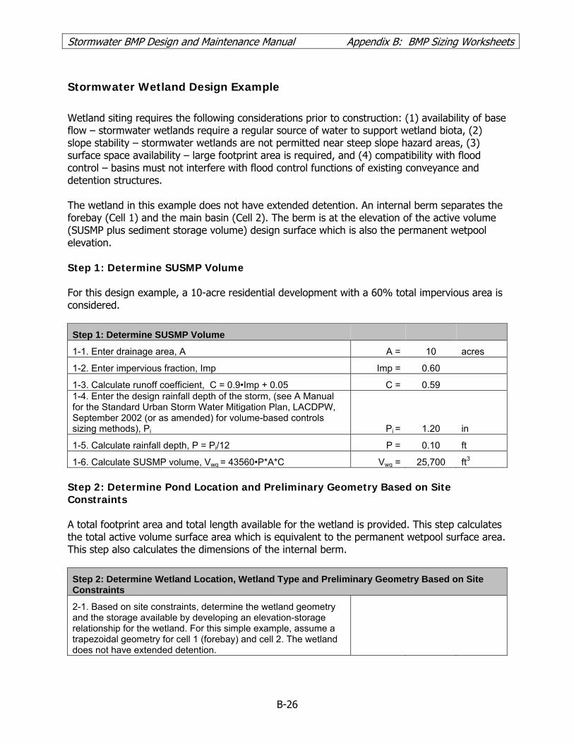
Stormwater BMP Design and Maintenance Manual Appendix B: BMP Sizing Worksheets
Stormwater Wetland Design Example
Wetland siting requires the following considerations prior to construction: (1) availability of base flow – stormwater wetlands require a regular source of water to support wetland biota, (2) slope stability – stormwater wetlands are not permitted near steep slope hazard areas, (3) surface space availability – large footprint area is required, and (4) compatibility with flood control – basins must not interfere with flood control functions of existing conveyance and detention structures. The wetland in this example does not have extended detention. An internal berm separates the forebay (Cell 1) and the main basin (Cell 2). The berm is at the elevation of the active volume (SUSMP plus sediment storage volume) design surface which is also the permanent wetpool elevation. Step 1: Determine SUSMP Volume For this design example, a 10-acre residential development with a 60% total impervious area is considered.
Step 1: Determine SUSMP Volume
1-1. Enter drainage area, A A = 10 acres
1-2. Enter impervious fraction, Imp Imp = 0.60
1-3. Calculate runoff coefficient, C = 0.9•Imp + 0.05 C = 0.59 1-4. Enter the design rainfall depth of the storm, (see A Manual for the Standard Urban Storm Water Mitigation Plan, LACDPW, September 2002 (or as amended) for volume-based controls sizing methods), Pi Pi = 1.20 in
1-5. Calculate rainfall depth, P = Pi/12 P = 0.10 ft
1-6. Calculate SUSMP volume, Vwq = 43560•P*A*C Vwq = 25,700 ft3 Step 2: Determine Pond Location and Preliminary Geometry Based on Site Constraints A total footprint area and total length available for the wetland is provided. This step calculates the total active volume surface area which is equivalent to the permanent wetpool surface area. This step also calculates the dimensions of the internal berm.
Step 2: Determine Wetland Location, Wetland Type and Preliminary Geometry Based on Site Constraints
2-1. Based on site constraints, determine the wetland geometry and the storage available by developing an elevation-storage relationship for the wetland. For this simple example, assume a trapezoidal geometry for cell 1 (forebay) and cell 2. The wetland does not have extended detention.
B-26

Stormwater BMP Design and Maintenance Manual Appendix B: BMP Sizing Worksheets
Step 2: Determine Wetland Location, Wetland Type and Preliminary Geometry Based on Site Constraints
2-2. Enter the total surface area of the wetland footprint based on site constraints, Atot Atot = 11,000 ft2
2-3. Enter the length of the wetland footprint based on site constraints, Ltot Ltot = 200 ft
2-4. Calculate the width of the wetland footprint, Wtot = Atot / Ltot Wtot = 55 ft 2-5. Enter interior side slope as length per unit height (min = 3), Z Z = 3 2-6. Enter desired freeboard depth, dfb dfb = 2 ft
2-7. Calculate the length of the SUSMP surface area including the internal berm but excluding freeboard, Lwq-tot = Ltot - 2Zdfb
Lwq-tot = 188 ft
2-8. Calculate the width of the SUSMP surface area including the internal berm but excluding freeboard, Wwq-tot = Wtot - 2Zdfb
Wwq-tot = 43 ft
2-9. Calculate the total SUSMP surface area including the internal berm and excluding freeboard, Awq-tot = Lwq-tot • Wwq-tot Awq-tot = 8,084 ft2
2-10. Enter the width of the internal berm (6 ft min), Wberm Wberm = 6 ft
2-11. Enter the length of the internal berm, Lberm = Wwq-tot Lberm = 43 ft
2-12. Calculate the area of the berm, Aberm = Wberm • Lberm Aberm = 258 ft2
2-13. Calculate the active volume surface area excluding the internal berm and freeboard, Awq = Awq-tot - Aberm Awq = 7,826 ft2
Step 3: Determine Dimensions of Cell 1 It should be assumed that cell 1 (the forebay) should be 15% of the SUSMP volume, Vwq.
Step 3: Determine Dimensions of Cell 1
3-1. Enter the percent of Vwq in Cell 1 (10-20% required), %V1 %V1 = 15 % 3-2. Calculate the active volume of Cell 1 (including sediment storage), V1 = (Vwq • %V1)/100 V1 = 3,855 ft3
3-3. Enter desired average depth of Cell 1 (5-9 ft including sediment storage of 1 ft), d1 d1 = 5
ft
3-4. Calculate the surface area for the SUSMP volume of Cell 1, A1 = V1 / d1 A1 = 771 ft2 3-5. Enter the width of Cell 1, W1 = Wav-tot = Lberm W1 = 43 ft 3-6. Calculate the length of Cell 1 (Note: inlet and outlet should be configured to maximize the residence time), L1 = A1 / W1 L1 = 18 ft
Step 4: Determine Dimensions of Cell 2 Verify that the surface area and length-to-width ratio of Cell 2 meet the design criteria. Calculate volumes, depths and surface areas for the very shallow, shallow and deep zones.
B-27

Stormwater BMP Design and Maintenance Manual Appendix B: BMP Sizing Worksheets
Step 4: Determine Dimensions of Cell 2 4-1. Calculate the active volume of Cell 2, V2 = Vwq - V1 V2 = 21,845 ft3 4-2. Calculate surface area of Cell 2, A2 = Awq - A1 A2 = 7,055 ft2
4-3. Enter width of Cell 2, W2 = W1 = Wwq-tot = Lberm W2 = 43 ft
4-4. Calculate top length of Cell 2, L2 = A2 / W2 L2 = 164 ft
4-5. Verify that the length-to-width ratio of Cell 2 is at least 3:1 with ≥ 4:1 preferred. If the length-to-width ratio is less than 3:1, modify input parameters until a ratio of at least 3:1 is achieved. If the input parameters cannot be modified as a result of site constraints, another site for the pond should be chosen, LW2 = L2 / W2 LW2 = 4
4-6. Enter percent of surface area of very shallow zone, %Avs %Avs = 15 ft2
4-7. Calculate very shallow zone surface area, Avs = (A2 • %Avs)/100 Avs = 1,058 ft2
4-8. Enter average depth of very shallow zone (0.1 - 1 ft), dvs dvs = 1 ft
4-9. Calculate volume of very shallow zone, Vvs = Avs • dvs Vvs = 1,058 ft3
4-10. Enter width of very shallow zone, Wvs = W2 Wvs = 43 ft
4-11. Calculate length of very shallow zone, Lvs = Avs / Wvs Lvs = 25 ft
4-12. Enter percent of surface area of shallow zone, %As %As = 55
4-13. Calculate surface area of shallow zone, As = (A2 • %As)/100 As = 3,880 ft2
4-14. Enter average depth of shallow zone (1 - 3 ft), ds ds = 3 ft
4-15. Calculate volume of shallow zone, Vs = As • ds Vs = 11,641 ft3
4-16. Enter width of shallow zone, Ws = W2 Ws = 43 ft
4-17. Calculate length of shallow zone, Ls = As / Ws Ls = 90 ft
4-18. Calculate surface area of deep zone, Adeep = A2 - Avs - As Adeep = 2,116 ft2
4-19. Calculate volume of deep zone, Vdeep = V2 - Vvs - Vs Vdeep = 9,146 ft3
4-20. Calculate average depth of deep zone (3 - 5 ft), ddeep = Vdeep / Adeep ddeep = 4 ft
4-21. Enter width of deep zone, Wdeep = W2 Wdeep = 43 ft
4-22. Calculate length of deep zone, Ldeep = Adeep / Wdeeo Ldeep = 49 ft Step 5: Ensure Design Requirements and Site Conditions are Achieved Check design requirements and site constraints. Modify design geometry until requirements are met. If the chosen site for the wetland is inadequate to meet the design requirements, choose a new location for the wetland or select and alternative treatment BMP.
B-28

Stormwater BMP Design and Maintenance Manual Appendix B: BMP Sizing Worksheets Step 6: Size Outlet Structure Please refer to Appendix C for wetland outlet structure sizing methodologies and examples. The wetland outlet pipe shall be sized, at a minimum, to pass flows greater than the SUSMP peak flow for off-line basins or flow from the capital storm for on-line basins. Step 7: Determine Emergency Spillway Requirements For online basins, an emergency overflow spillway should be sized to pass the capital design storm to prevent overtopping of the walls or berms in the event that a blockage of the riser occurs. For offline basins, an emergency spillway or riser should be sized to pass the SUSMP storm. For sites where the emergency spillway discharges to a steep slope, an emergency overflow riser, in addition to the spillway should be provided.
B-29

Stormwater BMP Design and Maintenance Manual Appendix B: BMP Sizing Worksheets
Sand Filters Worksheet
Step 1: Determine SUSMP volume
1-1. Enter drainage area, A A = acres
1-2. Enter impervious fraction, Imp Imp =
1-3. Calculate runoff coefficient, C = 0.9•Imp + 0.05 C = 1-4. Enter design rainfall depth of the storm, (see A Manual for the Standard Urban Storm Water Mitigation Plan, LACDPW, September 2002 (or as amended) for volume-based controls sizing methods), Pi Pi = in
1-5. Calculate rainfall depth, P = Pi/12 P = ft
1-6. Calculate SUSMP volume, Vwq=43560•P*A*C Vwq = ft3
Step 2: Calculate sand filter area
2-1. Enter thickness of sand filter (min. 2 ft, 3 ft preferred), L L = ft
2-2. Enter maximum storage depth (6 feet) above the filter, d d = ft
2-3. Enter routing adjustment factor, R R =
2-4. Calculate average depth of water above the filter, h = d/2 h = ft
2-5. Enter hydraulic conductivity (1"/hr), Ki Ki = in/hr
2-6. Calculate hydraulic conductivity (ft/day), Kday = 2Ki Kday = ft/day
2-7. Calculate hydraulic gradient, i = (h+L)/L i = ft/ft
2-8. Enter drawdown time, t t = day
2-9. Calculate sand filter area, Asf = (VwqRL)/(Kdayt(h+L)) Asf = ft2
Step 3: Determine filter dimensions
3-1. Sand filter area, Asf Asf = ft2
3-2. Enter geometric configuration, LR:W ratio (2:1), LR LR =
3-3. Calculate the width of the sand filter, W W = ft
3-4. Calculate the length of the sand filter, L L = ft
3-5. Calculate rate of filtration, rwq = Kdayi rwq = ft/d/ft2
Step 4: Calculate storage volume
4-1. Enter interior side slopes, 3H:1V(max), Z Z =
4-2. Calculate top length, Lt = L + 2Zd Lt = ft
4-3. Calculate top width, Wt = W +2Zd Wt = ft
4-4. Calculate filter storage volume, Vs = 1/3•d(Asf+At+(AsfAt)0.5) Where At = Lt*Wt Vs = ft3
B-30

Stormwater BMP Design and Maintenance Manual Appendix B: BMP Sizing Worksheets
Step 5: Calculate filter longitudinal underdrain collection pipe
5-1. Calculated filtered flow rate, Qf = rwqAsf Qf = cfs
5-2. Enter minimum slope for energy gradient, Se Se =
5-3. Enter Hazen-Williams coefficient for plastic, C C =
5-4. Enter pipe diameter, D D = in
5-5. Calculate pipe hydraulic radius, Rh =D/48 Rh = ft
5-6. Calculate velocity at the outlet of the pipe, Vp= 1.318CRh
0.63Se0.54 Vp = ft/s
5-7. Calculate pipe capacity, Qcap =0.25Π(D/12)^2Vp Qcap = cfs
Step 6: Provide conveyance capacity for filter clogging
6-1. The sand filters should be placed off-line, but an emergency overflow must still be provided in the event the filter becomes clogged and verify that all parameters meet design requirements to complete sizing.
B-31

Stormwater BMP Design and Maintenance Manual Appendix B: BMP Sizing Worksheets Sand Filter Design Example
Step 1: Determine SUSMP Volume For this design example, a 10-acre residential development with a 60% total impervious area is considered.
Step 1: Determine SUSMP volume
1-1. Enter drainage area, A A = 10 acres
1-2. Enter impervious fraction, Imp Imp = 0.60
1-3. Calculate runoff coefficient, C = 0.9•Imp + 0.05 C = 0.59 1-4. Enter design rainfall depth of the storm, (see A Manual for the Standard Urban Storm Water Mitigation Plan, LACDPW, September 2002 (or as amended) for volume-based controls sizing methods), Pi Pi = 1.2 in
1-5. Calculate rainfall depth, P = Pi/12 P = 0.10 ft
1-6. Calculate SUSMP volume, Vwq = 43560•P*A*C Vwq = 25,700 ft3 Step 2: Calculate Sand Filter Area A sand filter is designed with two components: (1) temporary storage reservoir to store runoff, and (2) a sand filter bed through which the stored runoff must percolate getting treatment. The simple sizing method does not rout flows through the filter. The size of the filter is determined based on the simple assumption that inflow is immediately discharged through the filter. The adjustment factor, R, is applied to compensate for the greater filter size resulting from this method.
Step 2: Calculate sand filter area
2-1. Enter thickness of sand filter (min. 24" or 2’), l l = 2 ft
2-2. Enter storage depth (6’ max.) above the filter, d d = 6 ft
2-3. Enter routing adjustment factor, R R = 0.7
2-4. Calculate average depth of water above the filter, h = d/2 h = 3 ft
2-5. Enter hydraulic conductivity (1"/hr), Ki Ki = 1 in/hr
2-6. Calculate hydraulic conductivity (ft/day), Kday = 2Ki Kday = 2 ft/day
2-7. Calculate hydraulic gradient, i = (h+l)/l i = 2.5 ft/ft
2-8. Enter drawdown time, t t = 2 day
2-9. Calculate sand filter area, Asf = (VwqRl)/(Kdayt(h+l)) Asf = 1,799 ft2 Step 3: Determine Filter Dimensions
Step 3: Determine filter dimensions
3-1. Sand filter area, Asf Asf = 1,799 ft2
B-32

Stormwater BMP Design and Maintenance Manual Appendix B: BMP Sizing Worksheets
B-33
Step 3: Determine filter dimensions
3-2. Enter geometric configuration, LR:W ratio (2:1 min.), LR LR = 2
3-3. Calculate the width of the sand filter, W W = 30.0 ft
3-4. Calculate the length of the sand filter, L L = 60.0 ft
3-5. Calculate rate of filtration, rwq = Kdayi rwq = 5.0 ft/d/ft2 Step 4: Calculate Storage Volume The side slopes are will be designed as 3H:1V, so Z = 3.
Step 4: Calculate storage volume
4-1. Enter interior side slopes, 3H:1V(max), Z Z = 3
4-2. Calculate top length, Lt = L + 2Zd Lt = 96.0 ft
4-3. Calculate top width, Wt = W + 2Zd Wt = 66.0 ft
4-4. Calculate filter storage volume, Vs = 1/3•d(Asf+At+(AsfAt)0.5), where At = Lt•Wt Vs = 23,018 ft3
Step 5: Calculate Filter Longitudinal Underdrain Collection Pipe All underdrain pipes must be 6 inches or greater to facilitate cleaning.
Step 5: Calculate filter longitudinal underdrain collection pipe 5-1. Calculated filtered flow rate, Qf = rwqAsf Qf = 0.10 cfs
5-2. Enter minimum slope for energy gradient, Se Se = 0.005
5-3. Enter Hazen-Williams coefficient for plastic, C C = 140
5-4. Enter pipe diameter, D D = 6 in
5-5. Calculate pipe hydraulic radius, Rh =D/48 Rh = 0.13
5-6. Calculate velocity at the outlet of the pipe, Vp= 1.318CRh
0.63Se0.54 Vp = 2.8 ft/s
5-7. Calculate pipe capacity, Qcap =0.25Π(D/12)^2Vp Qcap = 0.6 cfs Step 6: Provide Conveyance Capacity for Filter Clogging
The sand filters should be placed off-line, but an emergency overflow must still be provided in the event the filter becomes clogged and verify that all parameters meet design requirements to complete sizing.

Stormwater BMP Design and Maintenance Manual Appendix C: Pond Outlet Sizing Examples APPENDIX C POND OUTLET SIZING EXAMPLES
Perforated Risers Outlet Sizing Methodology (Figure 2-2)
The following factors are inputs to the perforated riser outlet sizing calculations:
• Shape of the pond (e.g. trapezoidal) • Depth and volume of the pond • Elevation / depth of first row of holes • Elevation / depth of last row of holes • Size of perforations • Number of rows or perforations and number of perforations per row • Desired draw down time (e.g. 16 hour and 32 hour draw down for top half and bottom
half respectively, 48 hour total draw down time) The governing the rate of discharge from a perforated riser structure can be calculated using Equation C-1 below:
23
232
HgHA
CQs
pp= (Equation C-1)
Where:
Q = riser flow discharge (cfs) Cp = discharge coefficient for perforations (use 0.61) Ap = cross-sectional area of all the holes (ft2) s = center to center vertical spacing between perforations (ft) Hs = distance from s/2 below the lowest row of holes to s/2
above the top row of holes (McEnroe 1988). H
H = distance from s/2 below the lowest row of holes to the water surface elevation under consideration.
For the iterative computations needed to size the perforations in the riser and determine the riser height a simplified version of Equation C-1 may be used, as shown below in Equation C-2:
23
kHQ = (Equation C-2) Where:
gHA
Cks
pp 2
32
= (Equation C-3)
C-1

Stormwater BMP Design and Maintenance Manual Appendix C: Pond Outlet Sizing Examples Uniformly perforated riser designs are defined by the depth or elevation of the first row of perforations, the length of the perforated section of pipe, and the size or diameter of each perforation. The steps needed to size a perforated riser outlet are outlined below. Step 1: Determine riser elevation or depth in the pond Set the riser elevation at 6” above the pond bottom to provide for sediment storage. Select a riser height such that the last row of perforations is inline with the top of the SUSMP pool elevation.
Step 2: Determine pond and riser attributes and constants for computations Parameters examined at this step include pond geometry such as pond shape, pond bottom length and width, and pond side slopes. Organize the attributes obtained in this step in a table such as Table C-1.
Step 3: Determine constant k Determine the value of the constant k (Equations C-2 and C-3) that provides the desired draw down time.
a. Set up a computation table such as Table C-3. Note that the table must have at least 19 height slices or the bottom 5% of the pond should be combined in the computations. The formulas for each column of the computation table are provided in Table C-2.
b. Using the pond depth, partition the pond into equal height horizontal slices to be
stored as entries in Table C-3. At each elevation En (or table entry), complete the following:
i. Determine the change in elevation Hn (ft) [Hn =( Eo – En+1)] ii. Calculate the average discharge Qn (cfs) [Qn =k(Hn)3/2 ] Eqn 3 iii. Calculate the pond surface area An (ft2) [An = L x W for rectangular
ponds] iv. Compute the available storage Vn (ft3) [Vn = An x Hn] v. Determine the average drain time Tn (hrs) [Tn = (Vn / Qn ) x 3600]
c. Sum up the drain times at each height slice to determine the total drain time for the
pond. If the value obtained is smaller or greater than the desired value, increase or decrease the k value and repeat the computations in step b until the desired drain time is achieved.
Step 4: Determine the size and number of rows of perforations Determine the size and number of rows of perforations that yield a k value equal to the k value used in the previous step. Follow the steps below to obtain riser attributes:
C-2

Stormwater BMP Design and Maintenance Manual Appendix C: Pond Outlet Sizing Examples
a. Select an initial number of rows, number or holes per row and an initial hole diameter.
b. Obtain flow area per row values from Table C-4 or compute flow area. c. Select a value for Hs and Cp and compute k. d. Repeat the above steps varying the number of rows, hole diameter, number of holes
per row and Hs until the desired value of k is obtained or it is determined that k is too small to be matched by any realistic combination of inputs. Hole diameter should not be less than 1/4" to minimize the potential for clogging.
Step 5: Verify the design The design is completed by verifying that the drain time for the both the top half and the bottom half are acceptable and the total drain time is equivalent to the desired value. Note that the drain time for the top half can be obtained by summing the drain times for the top half of the entries in the computation Table C-3. The drain time for the bottom half can similarly be obtained by summing values for the drain times for the bottom half of the entries in the computation Table C-3.
Table C-1: Constants Used in Example Computations
Constant Values Units Orifice coefficient (Cp) 0.6 - Perforation diameter (d) 0.0468 ft Combined area of holes (Ap) 0.0399 ft2 Acceleration due to gravity (g) 32.2 ft/s2 Pond bottom length (L) 40 ft Pond bottom width (W) 20 ft Side slopes (z) 3 - Pond bottom surface area (A) 800 ft2 k 0.02791 ft3/2/s
Table C-2: Pond Draw Down Time Calculation
Line No.
Elev. (ft)
Change in Elevation
(ft)
Average Discharge
(cfs)
**Pond Surface Area
(ft2)
Storage Volume
(ft3)
Average Drain Time
(hrs) 1 Eo Ho =( Eo – E1) Q0 =k(Ho)3/2 A0 = L x W Vo = Ao x Ho T0 = V0 / Q0 2 E1 H1 =( E1 – E2) Q1 =k(Ho)3/2 A1 = L x W V1 = A1 x H1 T1 = V1 / Q1 3 E2 H2 =( E2 – E1) Q2 =k(Ho)3/2 A2 = L x W V2 = A2 x H2 T2 = V2 / Q2 … … … … … … … * qadd is the additional flow from any additional orifices below the current elevation ** Pond surface area can be calculated or measured. Non rectangular cross sections must use the appropriate formulas for calculating cross-sectional areas.
C-3

Stormwater BMP Design and Maintenance Manual Appendix C: Pond Outlet Sizing Examples Table C-3: Sample Spread Sheet for Perforated Riser Outlet Sizing Calculations
Line No.
Elevation Change in height
Average Flow at Elev. (top orifice only)
Pond Surface Area
Storage Volume
Time to Drain
Unit at Current
Flow [En] [E1 - E2] [See Eqn 3] An [An x dH] [Vnv / Qn](ft) Hn (ft) Qn (cfs) (ft2) Vn (ft3) T (hrs)
1 6 0.3 0.4102 4256 1419 1.0 2 5.7 0.3 0.3765 3996 1332 1.0 3 5.3 0.3 0.3438 3744 1248 1.0 4 5.0 0.3 0.3120 3500 1167 1.0 5 4.7 0.3 0.2814 3264 1088 1.1 6 4.3 0.3 0.2518 3036 1012 1.1 7 4.0 0.3 0.2233 2816 939 1.2 8 3.7 0.3 0.1960 2604 868 1.2 9 3.3 0.3 0.1699 2400 800 1.3 10 3.0 0.3 0.1450 2204 735 1.4 11 2.7 0.3 0.1215 2016 672 1.5 12 2.3 0.3 0.0995 1836 612 1.7 13 2.0 0.3 0.0789 1664 555 2.0 14 1.7 0.3 0.0601 1500 500 2.3 15 1.3 0.3 0.0430 1344 448 2.9 16 1.0 0.3 0.0279 1196 399 4.0 17 0.7 0.3 0.0152 1056 352 6.4 18 0.3 0.3 0.0054 924 308 15.9 19 0.0 0.0 0.0000 800 0 0.0 Total Draw Down Time 48
C-4

Stormwater BMP Design and Maintenance Manual Appendix C: Pond Outlet Sizing Examples
Table C-4: Circular Perforation Sizing for Perforated Riser.
Source: UDFCD, 1999
C-5

Stormwater BMP Design and Maintenance Manual Appendix C: Pond Outlet Sizing Examples
Multiple Orifice Outlet Sizing Methodology
The following attributes influence multiple orifice outlet sizing calculations:
• Shape of the pond (e.g. trapezoidal) • Depth and volume of the pond • Elevation of each orifice • Desired draw-down time (e.g., 16 hour and 32 hour draw down times for top half and
bottom half respectively, 48 hour draw down time for whole pond ) The rate of discharge from a single orifice can be calculated using Equation C-4 below: (Equation C-4) 5.0)2( gHCAQ = Where:
Q = orifice flow discharge C = discharge coefficient A = cross-sectional area of orifice or pipe (ft2) g = acceleration due to gravity (32.2 ft/s2) H = effective head on the orifice (measured from center of orifice to water surface)
Multiple orifice designs are defined by the depth (or elevation) and the size (or diameter) of each orifice (Figure 2-1). The steps needed to size a dual orifice outlet are outlined below; multiple orifices may be provided and sized using a similar approach. Step 1: Determine orifice elevations
a. For the bottom orifice, set the orifice elevation (Hb) at a maximum of 6” above the pond bottom. If the bottom orifice is below the invert of the outlet pipe, then use the outlet pipe invert elevation for orifice calculations.
b. For the top orifice, set the orifice elevation (Ht) at half way to the top of the SUSMP
pool. Step 2: Determine pond and orifice attributes and constants for computations Parameters examined at this step include pond geometry such as pond shape, pond bottom length and bottom width and pond side slopes. Organize the attributes obtained in this step in a table such as Table C-5. Step 3: Determine the required size of the bottom orifice
a. Set up a computation table such as Table C-6. The formulas for each column of the computation table are provided in Table C-7.
b. Using the pond depth, partition the pond into equal height horizontal slices to be
stored as entries in Table C-6. At each elevation En (or table entry), complete the following:
C-6

Stormwater BMP Design and Maintenance Manual Appendix C: Pond Outlet Sizing Examples
i. Determine the change in elevation Hn (ft) [Hn =( Eo – En+1)] ii. Calculate the average discharge Qn (cfs) [Qn =CA(2gHn)0.5 ] Eqn 1 iii. Calculate the pond surface area An (ft2) [An = L x W for rectangular
ponds] iv. Compute the available storage Vn (ft3). [Vn = An x Hn] v. Determine the average drain time Tn (hrs) [Tn = (Vn / Qn)x 3600]
c. Sum up the drain times at each height slice to determine the total drain time for the
bottom half of the pond. If the value obtained is smaller or greater than the desired value, increase or decrease the orifice diameter and repeat the computations in step b above until the desired drain time is achieved
Step 4: Determine the required size of the top orifice
a. Set up a Table such as Table C-8. The formulas for each column of the computation tables are provided in Table C-7.
b. At each elevation En complete the following:
i. Determine the change in elevation Hn (ft) [Hn =( En – En+1)] ii. Calculate the average discharge Qn (cfs) [qn =CA(2gHn)0.5 ] Eqn 1 iii. Calculate the combine average discharge Q0 [Qn = qn + qadd] iv. Calculate the pond surface area An (ft2) [An = L x W for rectangular
ponds] v. Compute the available storage Vn (ft3) [Vn = An x Hn] vi. Determine the average drain time Tn (hrs) [Tn = Vn / Qn] vii. Note that qadd is the maximum discharge from the bottom orifice.
c. Sum up the drain times at each height slice to determine the total drain time for the
top half of the pond. If the value obtained is smaller than the desired value, increase or decrease the orifice diameter and repeat the computations in step 4b until the desired drain time is achieved.
Step 5: Verify the design The design is completed by verifying that the sum of the detention times for the top half of the pond and the bottom half of the pond add up to the total desired detention time (36 to 48 hours).
C-7

Stormwater BMP Design and Maintenance Manual Appendix C: Pond Outlet Sizing Examples Table C-5: Constants Used in Example Computations
Constant Lower Orifice Values Upper Orifice Values Units Orifice coefficient (Cp) 0.6 0.6 - Orifice diameter (d) 0.0633 0.0675 ft Orifice cross-sectional area (a) 0.003 0.004 ft2 Acceleration due to gravity (g) 32.2 32.2 ft/s2 Pond bottom length (L) 40 40 ft Pond bottom width (W) 20 20 ft Side slopes (z) 3 3 - Pond bottom surface area (A) 800 800 ft2
Table C-6: Sample Spreadsheet for Dual Orifice Pond Outlet Sizing Calculations: Bottom Half of Pond
Line Number
Elevation [E]
Change in height
Average Flow at Elev. (top orifice only)
Pond Surface Area
Storage Volume
Time to Drain Unit at
Current Flow Rate
[E1-E2] [See Eqn 1] Aelev [Aelev x dH] [Velev / Qelev] (ft) H (ft) qtop (cfs) (ft2) Velev (ft3) T (hrs)
1 3.0 3.0 0.0567 2204 735 3.6 2 2.7 2.7 0.0534 2016 672 3.5 3 2.3 2.3 0.0500 1836 612 3.4 4 2.0 2.0 0.0463 1664 555 3.3 5 1.7 1.7 0.0422 1500 500 3.3 6 1.3 1.3 0.0378 1344 448 3.3 7 1.0 1.0 0.0327 1196 399 3.4 8 0.7 0.7 0.0267 1056 352 3.7 9 0.3 0.3 0.0189 924 308 4.5 10 0.0 0.0 0.0000 800 0 0.0
Subtotal Draw Down Time 32.0
Table C-7: Pond Draw Down Time Calculation
Line No.
Elev. (ft)
Change in Elevation (ft)
Average Discharge
(cfs)
*Combined Average
Discharge (cfs)
**Pond Surface
Area (ft2)
Storage Volume
(ft3)
Average Drain Time
(hrs) 1 Eo Ho =( Eo – E1) q0
=CA(2gHo)0.5 Q1 = q1 + qadd A0 = L x W Vo = Ao x Ho T0 = V0 / Q0
2 E1 H1 =( E1 – E2) q1
=CA(2gHo)0.5 Q2 = q2 + qadd A1 = L x W V1 = A1 x H1 T1 = V1 / Q1
3 E2 H2 =( E2 – E1) q2
=CA(2gHo)0.5 Q3 = q3 + qadd A2 = L x W V2 = A2 x H2 T2 = V2 / Q2
… … … … … … … … * qadd is the additional flow from any additional orifices below the current elevation ** Pond surface area can be calculated or measured. Non-rectangular cross sections must use the appropriate formulas for calculating cross-sectional areas.
C-8

Stormwater BMP Design and Maintenance Manual Appendix C: Pond Outlet Sizing Examples
C-9
Table C-8: Sample Spreadsheet for Dual Orifice Pond Outlet Sizing Calculations: Top Half of Pond
Line Number
Elevation Change
in height
Average Flow at
Elev. (top orifice only)
Combined Average
Discharge
Pond Surface
Area
Storage Volume
Time to Drain Unit at
Current Flow
[E] [E1 - E2] [See Eqn 1] [qtop + qbot] Aelev
[Aelev x dH] [Velev / Qelev]
(ft) H (ft) qtop (cfs) Qelev (cfs) (ft2) Velev (ft3) T (hrs)
1 6.0 3.0 0.1615 0.2181 4256 1419 1.8 2 5.7 2.7 0.1522 0.2089 3996 1332 1.8 3 5.3 2.3 0.1424 0.1990 3744 1248 1.7 4 5.0 2.0 0.1318 0.1885 3500 1167 1.7 5 4.7 1.7 0.1203 0.1770 3264 1088 1.7 6 4.3 1.3 0.1076 0.1643 3036 1012 1.7 7 4.0 1.0 0.0932 0.1499 2816 939 1.7 8 3.7 0.7 0.0761 0.1328 2604 868 1.8 9 3.3 0.3 0.0538 0.1105 2400 800 2.0 10 3.0 0.0 0.0000 0.0567 2204 0 0.0
Subtotal Draw Down Time 16.0
Total Draw Down Time 48.0

Stormwater BMP Design and Maintenance Manual Appendix D: Flow Splitters
APPENDIX D FLOW SPLITTER DESIGN SPECIFICATION
Flow splitters must be provided for off-line facilities to divert the SUSMP flow to the BMP and bypass higher flows. In most cases, it is a designer's choice whether stormwater treatment BMPs described in this manual are designed as on-line or off-line; an exception are filter strips and planter boxes which are always designed on-line. A crucial factor in designing flow splitters is to ensure that low flows are delivered to the treatment facility up to the SUSMP flow rate. Above this rate, additional flows remain in the storm drain or are diverted to a bypass drain with minimal increase in head at the flow splitter structure to avoid surcharging the SUSMP facility under high flow conditions. Flow splitters are typically manholes or vaults with weirs. In place of weirs, the splitter mechanism may be a half tee section with a solid top and an orifice in the bottom of the tee section. A full tee option may also be used (see "Design Criteria" below). Two possible design options for flow splitters are shown in Figures D1 and D2. Other equivalent designs that achieve the result of splitting low flows, up to the SUSMP design flow, into the treatment facility and divert higher flows around the facility are also acceptable. Flow splitters may be modeled using standard level pool routing techniques, as described in the Handbook of Applied Hydrology (Chow, Ven Te, 1964) and elsewhere. The stage/discharge relationship of the outflow pipes should be determined using backwater analysis techniques. Orifices, if used, may be designed using the approach outlined in “Outlet Structure and Drawdown Time” in Chapter 2, Extended Detention Basins. Weirs should be analyzed as sharp-crested weirs.
Design Criteria
1. A flow splitter shall be designed to deliver the required SUSMP flow rate to the stormwater treatment facility.
2. The top of the weir shall be located at the water surface corresponding to the design flow.
Higher flows enter the bypass line. 3. Capital storm flows to the treatment facility shall not increase the design SUSMP flow by
more than 10%. 4. Example designs are shown in Figure D1 and Figure D2. Equivalent designs are also
acceptable. 5. Special applications, such as roads, may require the use of a modified flow splitter. The weir
wall may be fitted with a notch and adjustable weir plate to proportion runoff volumes other than high flows.
6. For ponding facilities, backwater effects must be included in designing the height of the
standpipe in the manhole/vault (Option B).
D-1

Stormwater BMP Design and Maintenance Manual Appendix D: Flow Splitters 7. Ladder or step and handhold access shall be provided. If the weir wall is higher than 36
inches, two ladders, on the either side of the wall, are required.
Material Requirements
1. The splitter baffle shall be installed in a standard manhole or vault. The baffle wall shall be made of material resistant to corrosion (minimum 4-inch thick reinforced concrete, Type 302 or Type 316 stainless steel plate, or equivalent).
2. The minimum clearance between the top of the weir wall and the bottom of the manhole or
vault cover shall be 4 feet; otherwise, dual access points shall be provided. 3. All metal parts shall be corrosion resistant. Examples of preferred materials include
aluminum, stainless steel, and plastic. Copper, zinc and galvanized materials are not permitted because of aquatic toxicity. Painting metal parts shall not be allowed because of poor longevity.
D-2


Stormwater BMP Design and Maintenance Manual Appendix E: Facility Inspection
APPENDIX E FACILITY INSPECTION
Introduction
To ensure high-quality, long-term performance, BMPs need to be inspected on a regular basis. These inspections help the stormwater manager monitor the safety, longevity, and effectiveness of these practices over time. BMP maintenance inspections are intended to do the following:
• Ensure the facilities are generally safe • Maintain the proper stormwater management capacity and cost-effectiveness • Comply with reporting to regulatory agencies • Provide BMP tracking data • Follow standard engineering practices
Inspection Types and Frequency
Inspection types range in detail from a low level (e.g., drive by) to a high level (e.g., rigorous professional inspection). Inspection frequency depends on many factors including the type of facility, accessibility to the public, likelihood of vandalism, and major storm events. Regular inspections include observations on general appearance, damage by water or vandalism, erosion, plant loss, trash and debris accumulation, standing water (where there shouldn’t be), obvious (visual) loss of functionality, and vegetation condition. Such inspections should occur at:
• regular intervals for aesthetics, vegetation maintenance and checking for vandal damage,
• after large storms and at the end of the rainfall season for possible flow damage, and • before winter storms to ensure the facility is properly prepared to handle the coming
runoff events. Annual or semi-annual inspections would include these and other more rigorous evaluations. The instructions for operations and maintenance in this Manual include suggested inspection frequencies for each BMP type.
Procedures
Pre-Inspection Preparation
Prior to BMP inspection, the inspector(s) will have to gather a number of materials and equipment that fall under three categories:
Public Communications Materials
General educational materials as well as jurisdiction program and contact information may be used to help address questions or comments raised by inquisitive residential or commercial property owners encountered during the inspection.
E-1

Stormwater BMP Design and Maintenance Manual Appendix E: Facility Inspection BMP Background Information
Historical information on each BMP to be inspected will ease the inspection process and help to ensure that past maintenance or structural problems have been addressed. As-builts drawings are particularly helpful if available.
Inspection Checklists
Standard inspection checklists are used to record the condition of all facilities, and particularly those that need frequent maintenance. It will also be easier to track maintenance electronically, using either a database or spreadsheet, rather than relying on paper files. Well-designed checklists can be integrated with these systems to prioritize maintenance, track performance over time, and relate design characteristics to particular problems. To effectively achieve these goals, the checklist should:
• Be quantitative, so that maintenance can be easily prioritized. • Be very specific about possible problems to reduce subjectivity. • Limit the use of text, particularly if integrated with a database. • Link problems to specific actions. • Where possible, track the function of the facility over time for future research and
design. Inspection checklists should also be grouped in the order the inspector would inspect the practice. For example, ponds should typically be inspected from downstream to upstream, so the investigation begins with the outfall channel. Checklists are presented in Appendix F.
Inspection Equipment
A range of equipment is necessary to perform a comprehensive, safe inspection of a facility. A list of the materials and equipment that could potentially accompany any inspector is presented in Table E-1 below. Actual equipment needed for inspection is determined by the type of facility being inspected and the level of detail of the inspection. Table E-1: Inspection Equipment BMP Inspection Equipment/Materials Quantity Required for Public communications materials Jurisdiction permission letter (for 3rd party inspectors)
multiple All BMPs
Jurisdiction contact list multiple All BMPs BMP-Specific Information
Blank inspection checklists multiple All BMPs Site plans/as-built drawings per facility All BMPs Facility type and outfall pipe size per facility All BMPs Facility location per facility All BMPs Previous inspection results (reports, redlines and photos)
per facility All BMPs
Confined space entry permit (as needed) per facility Underground Confined Space Entry (CSE)
E-2

Stormwater BMP Design and Maintenance Manual Appendix E: Facility Inspection
Inspection Equipment Clipboard w/forms, pencil and compass 1 All BMPs Area map 1 All BMPs Mobile telephone 1 All BMPs Two-way radio w/charged batteries 2 All BMPs 100' measuring tape 1 All BMPs 25' retractable scale 1 All BMPs Bolt cutters 1 All BMPs Cans of orange spray paint 2 All BMPs Crow bar 1 All BMPs Digital camera 1 All BMPs First aid kit 1 All BMPs Flashlight w/charged batteries 1 All BMPs Goggles or safety glasses 2 All BMPs Hardhats 2 All BMPs Leather gloves 2 All BMPs Manhole cover tool / puller 1 All BMPs Pair of hard sole boots (wear) 2 All BMPs Pair of rubber boots (as-needed) 2 All BMPs Roll of orange tie-off tape 1 All BMPs Std. size bolt locks and keys (for gates) 2 All BMPs Waterproof carrying bag 1 All BMPs Machete or pruning sheers 1 Above ground Monkey wrench 1 Above ground Standard shovel 1 Above ground Observation well cap wrenches 1/Size Infiltration facilities only Small size bolt lock and key (for well caps) 1 Infiltration facilities only 100' rope 1 Underground CSE Air monitor/meter w/charged batteries 1 Underground CSE Orange pylons/traffic cones 4 Underground CSE Spot light 1 Underground CSE 5 minute air supply 1 Underground CSE Full face respirator 1 Underground CSE Recalibration kit 1 Underground CSE Ventilation/forced air blower 1 Underground CSE
Pre-Inspection Notification
Inspection and maintenance of BMPs is often the responsibility of two separate entities. Since the local government is accountable for ensuring the region's stormwater management system is operating within State and Federal regulations, inspections are typically conducted by either government personnel or a private contractor under government authority. However, the duty of maintaining the site frequently falls to the hands of a private homeowner, homeowner association or commercial property owner. Communication between the local government and the BMP manager/owner is key to ensuring long-term and effective BMP operation. All correspondence should provide detailed information about what the BMP manager/owner can expect. This will allow the BMP manager/owner to better understand and be prepared for the role he/she or the community plays during the entire process. Effective communication can eliminate unnecessary concerns and confusion on the part of the BMP owner and provide a
E-3

Stormwater BMP Design and Maintenance Manual Appendix E: Facility Inspection base for legal action for the enforcing agency. The greater the clarity, the smoother the process will be for all involved. Prior to inspection, a Notification of Inspection Letter should be sent to the BMP manager/owner. An example of this letter is included in Appendix G. This letter serves several purposes: 1. Informs the manager that he/she should expect someone to be on their property. 2. Encourages routine maintenance to be performed. 3. Notifies the manager of any special pre-inspection actions that must be completed. 4. Secures the name of the person who oversees the maintenance of the BMP. A Notification of Inspection Letter should include the basic information listed above, along with all of the following information:
Date of Future Inspection
This could either be a specific day or a period, such as a week, that the BMP manager/owner would expect a local government inspector to be on the property.
Request for current maintenance manager contact information
Finding this information ahead of time will save time later when trying to ensure the repairs are completed.
Special Instructions
For example, the BMP manager/owner may be responsible for pumping out and pressure washing underground facilities prior to inspection.
Outline of Inspection Process
Provide as much detail as possible, such as, "The inspection will be sometime in the morning during the second week in August by Inspector. Within 14 days of inspection, you will be notified of any repairs that are required. You will then have 30 days to fix any deficiencies..." In summary, all correspondence should include the following basic information: 1. Facility address and BMP owner's address are both essential because it possible that the
owner is in charge of multiple sites. 2. Facility identification number provides an internal reference for the inspecting unit and for
BMP owners that may have more than one BMP at the same address. 3. BMP owner name and title. Since homeowners, homeowner associations, and property
managers can change without notice it is critical to include both the name and title, such as "John Doe or Current Property Manager/Owner," to ensure the letter reaches the appropriate person.
4. Description of Authority tells the manager by which regulation/code the local government gains authority to inspect the site and require repairs.
E-4

Stormwater BMP Design and Maintenance Manual Appendix E: Facility Inspection 5. Deadline by which a response or repair should be made. 6. Consequences if response or repairs are not made. 7. Contact information for the person to whom the manager/owner can speak for assistance.
Health and Safety
Safety is a critical element of any operations and maintenance plan. Potential hazards associated with operating and maintaining BMP facilities include physical hazards that may develop as a result of automobile traffic, inclement weather conditions, high flow conditions, and steep or difficult terrain; electrical/mechanical hazards from motorized-valves and controls, atmospheric hazards resulting from poor ventilation in confined spaces, and chemical hazards from materials that may be present in urban runoff or in products used to clean/maintain various equipment. A Health and Safety Plan approved by the County’s Health and Safety Coordinator should be reviewed by the all field personnel before inspections begin. All persons involved in inspections should be made aware of the hazards associated with inspection and should freely voice any concerns if potential hazards become apparent. The Occupational Safety and Health Administration (OSHA) provides regulations and guidance on occupational safety, many of which are directly applicable to the types of activities involved in inspection. It is the direct responsibility of each person involved in the inspection program to read the Health and Safety Plan and adhere to its requirements. Operation and maintenance personnel are responsible for assessing the individual site conditions to identify possible hazards, selecting safety equipment, and implementing appropriate safety precautions. Under no circumstances should inspection and/or maintenance activities be conducted if there is a significant safety concern that cannot be adequately addressed. The following list provides a few basic health and safety procedures that can help to create a safer sampling environment:
• Do not enter a confined space (e.g., StormFilter™ vault) without proper training, equipment, and surface support.
• Never remove or replace manhole covers with your bare hands or feet. • Never leave an open manhole unattended. • Do not start staging or sampling until traffic control has been established. • Follow manufacturer's instructions when operating mechanical equipment. • Standard precautions should be taken when operating electrical equipment due to the
moist conditions that will prevail at many of the installations (e.g., outdoor equipment panels).
E-5

Stormwater BMP Design and Maintenance Manual Appendix E: Facility Inspection Maintenance operations will normally be conducted under dry conditions when the facility is more accessible and the potential for many physical hazards is low. However, inspection activities may be conducted during storm events to evaluate how the system is operating. When working near open water it is important to be aware of and avoid drowning hazards. High stormwater flows often carry branches and other debris that can entangle a person or pin them beneath submerged obstacles. Creek banks can be unstable or slippery during wet weather and caution should be observed when walking on wet unstable surfaces.
Problem Identification
Inspectors should clearly identify the extent and location of problems identified during inspection. In addition to clearly describing problem areas on the checklists, inspectors should help repair crews locate repairs both at the site and on design plans.
Immediate Concerns
While all maintenance and inspection items are important, some maintenance concerns actually pose an immediate safety concern. Many of these are caused by missing or damaged elements that would prevent access by the public. Examples include missing manhole covers or trash racks, missing or damaged fencing when that fence prevents access to a pond with steep side slopes, or a missing or damaged grate at a large inflow or outfall pipe. Another set of immediate pond and wetland repairs involve dam safety or flooding hazards. If a practice shows signs of embankment failure, or if an inspector is unsure, an appropriately qualified person or engineer should be called in to investigate the situation immediately. Similarly, cracks in a concrete riser that drains a large area may pose a dam safety threat
As-built Drawings
The inspector should bring a copy of the as-built plan of the facility to mark potential corrections and problem areas on this plan. The marked up as-built plan should be stored either digitally or in a paper file system so that it can be brought out to confirm that maintenance was performed correctly on the follow-up inspection.
Photographs
Inspectors should take a core set of documentation photographs of practices being inspected. In addition, specific problem areas should be photo documented. A recommended set of core photographs include:
• Vehicle access points. • Overview of the facility. • Overview of principal intake structure. • Inlet to facility and downstream outfall from facility. • Emergency spillway (if applicable).
E-6

Stormwater BMP Design and Maintenance Manual Appendix E: Facility Inspection In addition, because of the large number of photographs that will likely be generated, a digital camera should be used to allow photographs to be stored electronically. (In advanced database programs, these photographs can be retrieved digitally). Finally, photographs should be named using a standard convention. The photograph name should indicate the practice identification number, feature (or problem) being photographed, and date of photograph.
Field Marking
Inspectors can highlight key areas of concern with spray paint or other marker. This is particularly useful for problems that may otherwise be difficult to find by others. Marking should be used as discretely as possible. For example, only dots sprayed at the base of trees should be used to mark limits of clearing for vegetation removal.
Post Inspection Follow Up and Maintenance Request Procedure
Once the BMP has been inspected, the BMP manager/owner should be informed of the BMP status and any repairs that need to be made through a Maintenance Notification Letter if privately owned, or through a Maintenance Request Order if the facility is maintained by the County. An example of the Maintenance Notification Letter is included in Appendix G. This letter should include the basic inspection information with the additional information below.
List of Repairs
This list should be detailed enough so it cannot be misinterpreted. For example, avoid ambiguous phrases such as "clear the bank." Instead, the list should specify "clear the bank of dead vegetation."
Outline of the Repair Process
This can expedite the repairs, particularly if the BMP manager/owner does not have previous experience with BMPs. In most cases it is worthwhile to suggest the use of a contractor to dissuade unqualified persons from performing the repairs. For example, "You will have 30 days to complete the repairs. The first step is to get bids from contractors. Next, your contractor should contact our inspector to discuss repairs. . ." A facility inspection report should be attached for the BMP manager's/owner's records.
Educational material
Educational materials should also be attached to reinforce why properly maintaining BMPs is important not only for environmental reasons but also how good stormwater management serves their best interests.
Notification of Violation
In situations when a BMP manager/owner fails to comply with a Maintenance Notification Letter and/or other requests for compliance, a letter using strong language should be sent. These
E-7

Stormwater BMP Design and Maintenance Manual Appendix E: Facility Inspection
E-8
notices are typically more formal than Maintenance Notification Letters and have a strong emphasis on the consequences if the manger/owner does not remedy the situation. Notices of Violation should include the basic information, plus:
1. Reference(s) to previous correspondence, which can provide a paper trail in cases when disagreement of roles arises.
2. List of repairs that should be detailed enough so it cannot be misinterpreted
3. List of violations the BMP manager/owner has accrued, including actions such as failing
to comply with previous notices. Copies of this letter may be sent to other agencies affected, e.g., such as those responsible for dam safety, etc. An example of this letter is included in Appendix G.

Stormwater BMP Design and Maintenance Manual Appendix F: Facility Inspection and Maintenance Checklist
APPENDIX F FACILITY INSPECTION AND MAINTENANCE CHECKLIST
Included in this appendix are a series of checklists that can be used by both inspectors and maintenance personnel to ensure that observed deficiencies in BMPs are maintained appropriately. The checklists are ordered as follows:
1. Detention Basin Inspection/Maintenance Checklist 2. Vegetated Swale Inspection/Maintenance Checklist 3. Filter Strip Inspection/Maintenance Checklist 4. Bioretention Inspection/Maintenance Checklist 5. Planter Box Inspection/Maintenance Checklist 6. Infiltration Trench Inspection/Maintenance Checklist 7. Hydrodynamic Separation Device Inspection/Maintenance Checklist 8. Catch Basin Insert Inspection/Maintenance Checklist 9. Cartridge Media Filter Inspection/Maintenance Checklist
F-1

Stormwater BMP Design and Maintenance Manual Appendix F: Facility Inspection and Maintenance Checklist
Extended Detention Basin Inspection and Maintenance Checklist Date: Work Order # Type of Inspection: □ post-storm □ annual □ routine □ post-wet season □ pre-wet season Facility: Inspector(s):
Defect Conditions When Maintenance Is Needed
Inspection Result (0, 1 or 2)†
Date Maintenance Performed
Comments or Action(s) Taken to Resolve Issue
General Appearance Untidy, un-mown (if applicable)
Vegetation
Access problems or hazards; dead or dying trees
Poisonous or nuisance vegetation or noxious weeds
Insects Insects such as wasps and hornets interfere with maintenance activities.
Rodent Holes
Any evidence of rodent holes if facility is acting as a dam or berm, or any evidence of water piping through dam or berm via rodent holes
Trash and Debris Trash and debris > 5 cf/1,000 sf (one standard size garbage can).
Pollutants Any evidence of oil, gasoline, contaminants or other pollutants
Inlet/Outlet Pipe Inlet/Outlet pipe clogged with sediment and/or debris. Basin not draining.
Erosion
Erosion of the basin’s side slopes and/or scouring of the basin bottom that exceeds 2-inches, or where continued erosion is prevalent.
Piping Evidence of or visible water flow through basin berm.
Settlement of Basin Dike/Berm
Any part of these components that has settled 4-inches or lower than the design elevation, or inspector determines dike/berm is unsound.
Overflow Spillway Rock is missing and/or soil is exposed at top of spillway or outside slope.
Sediment Accumulation in Basin Bottom
Sediment accumulations in basin bottom that exceeds the depth of sediment zone plus 6-inches.
Tree or shrub growth
Trees > 4 ft in height with potential blockage of inlet, outlet or spillway; or potential future bank stability problems
Debris Barriers (e.g., Trash Racks)
Trash and Debris Trash or debris that is plugging more than 20% of the openings in the barrier.
†Maintenance: Enter 0 if satisfactory, 1 if maintenance is needed and include WO#. Enter 2 if maintenance was performed same day.

Stormwater BMP Design and Maintenance Manual Appendix F: Facility Inspection and Maintenance Checklist
†Maintenance: Enter 0 if satisfactory, 1 if maintenance is needed and include WO#. Enter 2 if maintenance was performed same day.
Defect Conditions When Maintenance Is Needed
Inspection Result (0, 1 or 2)†
Date Maintenance Performed
Comments or Action(s) Taken to Resolve Issue
Damaged/ Missing Bars
Bars are bent out of shape more than 3 inches.
Bars are missing or entire barrier missing. Bars are loose and rust is causing 50% deterioration to any part of barrier.
Inlet/Outlet Pipe Debris barrier missing or not attached to pipe.
Fencing
Missing or broken parts
Any defect in the fence that permits easy entry to a facility.
Erosion Erosion more than 4 inches high and 12-18 inches wide, creating an opening under the fence.
Damaged Parts Damage to gate/fence, posts out of plumb, or rails bent more than 6 inches.
Deteriorating Paint or Protective Coating
Part or parts that have a rusting or scaling condition that has affected structural adequacy.
Gates
Damaged or missing member
Missing gate or locking devices, broken or missing hinges, out of plum more than 6 inches and more than 1 foot out of design alignment, or missing stretcher bar, stretcher bands, and ties.

Stormwater BMP Design and Maintenance Manual Appendix F: Facility Inspection and Maintenance Checklist
Vegetated Swale Inspection and Maintenance Checklist Date: Work Order # Type of Inspection: □ post-storm □ annual □ routine □ post-wet season □ pre-wet season Facility: Inspector(s):
Defect Conditions When Maintenance Is Needed
Inspection Result (0, 1, or 2)†
Date Maintenance Performed
Comments or Action(s) Taken to Resolve Issue
Appearance Untidy Trash and Debris Accumulation
Trash and debris accumulated in the swale.
Vegetation
When the grass becomes excessively tall (greater than 10-inches); when nuisance weeds and other vegetation start to take over.
Excessive Shading Vegetation growth is poor because sunlight does not reach swale. Evaluate vegetation suitability.
Poor Vegetation Coverage
When vegetation is sparse or bare or eroded patches occur in more than 10% of the swale bottom. Evaluate vegetation suitability.
Sediment Accumulation
Sediment depth exceeds 2 inches or covers more than 10% of design area.
Standing Water When water stands in the swale between storms and does not drain freely.
Flow spreader or Check Dams
Flow spreader or check dams uneven or clogged so that flows are not uniformly distributed through entire swale width.
Constant Baseflow
When small quantities of water continually flow through the swale, even when it has been dry for weeks and an eroded, muddy channel has formed in the swale bottom.
Inlet/Outlet Inlet/outlet areas clogged with sediment and/or debris.
Erosion/ Scouring
Eroded or scoured swale bottom due to flow channelization, or higher flows. Eroded or rilled side slopes.
Eroded or undercut inlet/outlet structures
†Maintenance: Enter 0 if satisfactory, 1 if maintenance is needed and include WO#. Enter 2 if maintenance was performed same day.

Stormwater BMP Design and Maintenance Manual Appendix F: Facility Inspection and Maintenance Checklist
Filter Strip Inspection and Maintenance Checklist Date: Work Order # Type of Inspection: □ post-storm □ annual □ routine □ post-wet season □ pre-wet season Facility: Inspector(s):
Defect Conditions When Maintenance Is Needed
Inspection Result (0, 1 or 2)†
Date Maintenance Performed
Comments or Action(s) Taken to Resolve Issue
Appearance Untidy
Trash and Debris Accumulation
Trash and debris accumulated on the filter strip.
Vegetation
When the grass becomes excessively tall (greater than 10-inches); when nuisance weeds and other vegetation starts to take over.
Excessive Shading Grass growth is poor because sunlight does not reach swale. Evaluate grass species suitability.
Poor Vegetation Coverage
When grass is sparse or bare or eroded patches occur in more than 10% of the swale bottom. Evaluate grass species suitability.
Erosion/Scouring Eroded or scoured areas due to flow channelization, or higher flows.
Sediment Accumulation on Grass
Sediment depth exceeds 2 inches.
Flow spreader Flow spreader uneven or clogged so that flows are not uniformly distributed through entire filter width.
†Maintenance: Enter 0 if satisfactory, 1 if maintenance is needed and include WO#. Enter 2 if maintenance was performed same day.

Stormwater BMP Design and Maintenance Manual Appendix F: Facility Inspection and Maintenance Checklist
Bioretention Inspection and Maintenance Checklist Date: Work Order # Type of Inspection: □ post-storm □ annual □ routine □ post-wet season □ pre-wet season Facility: Inspector(s):
Defect Conditions When Maintenance Is Needed
Inspection Result (0, 1, or 2)†
Date Maintenance Performed
Comments or Action(s) Taken to Resolve Issue
Appearance Untidy
Trash and Debris Accumulation
Trash, plant litter and dead leaves accumulated on surface.
Vegetation Unhealthy plants and appearance.
Irrigation Functioning incorrectly (if applicable).
Inlet Inlet pipe blocked or impeded.
Splash Blocks Blocks or pads correctly positioned to prevent erosion.
Overflow Overflow pipe blocked or broken.
Filter media Infiltration design rate is met (e.g., drains 36-48 hours after moderate - large storm event).
†Maintenance: Enter 0 if satisfactory, 1 if maintenance is needed and include WO#. Enter 2 if maintenance was performed same day.

Stormwater BMP Design and Maintenance Manual Appendix F: Facility Inspection and Maintenance Checklist
Planter Box Inspection and Maintenance Checklist Date: Work Order # Type of Inspection: □ post-storm □ annual □ routine □ post-wet season □ pre-wet season Facility: Inspector(s):
Defect Conditions When Maintenance Is Needed
Inspection Result (0, 1, or 2)†
Date Maintenance Performed
Comments or Action(s) Taken to Resolve Issue
Appearance Untidy
Trash and Debris Accumulation
Trash, plant litter and dead leaves accumulated on surface.
Vegetation
Unhealthy plants and appearance.
Vegetation interfering with planter operations.
Irrigation Functioning incorrectly (if applicable).
Plant box Structural defects, holes and gaps.
Inlet Inlet pipe blocked or impeded.
Splash Blocks Blocks or pads correctly positioned to prevent erosion.
Overflow Overflow pipe blocked or broken.
Filter media Infiltration design rate is met (e.g., drains 3-4 hours after moderate - large storm event).
†Maintenance: Enter 0 if satisfactory, 1 if maintenance is needed and include WO#. Enter 2 if maintenance was performed same day.

Stormwater BMP Design and Maintenance Manual Appendix F: Facility Inspection and Maintenance Checklist
Infiltration Trench Inspection and Maintenance Checklist Date: Work Order # Type of Inspection: □ post-storm □ annual □ routine □ post-wet season □ pre-wet season Facility: Inspector(s):
Defect Conditions When Maintenance Is Needed
Inspection Result (0,1, or 2) †
Date Maintenance Performed
Comments or Action(s) Taken to Resolve Issue
Appearance, vegetative health
Mowing and trimming vegetation is needed to prevent establishment of woody vegetation, and for aesthetic and vector reasons.
Vegetation
Poisonous or nuisance vegetation or noxious weeds.
Excessive loss of turf or ground cover (if applicable).
Trash & Debris Trash and debris > 5 cf/1,000 sf (one standard size garbage can).
Contaminants and Pollution
Any evidence of oil, gasoline, contaminants or other pollutants.
Erosion Undercut or eroded areas at inlet or outlet structures.
Sediment and Debris
Accumulation of sediment, debris, and oil/grease on surface, inflow, outlet or overflow structures.
Sediment and Debris
Accumulation of sediment and debris, in sediment forebay and pretreatment devices.
Water drainage rate
Standing water, or by visual inspection of wells (if available), indicates design drain times are not being achieved (i.e., within 72 hours).
Media clogging surface layer
Lift surface layer (and filter fabric if installed) and check for media clogging with sediment (function may be able to be restored by replacing surface aggregate/filter cloth).
Media clogging
Lift surface layer (and filter fabric if installed) and check for media clogging with sediment (partial or complete clogging which may require full replacement).
†Maintenance: Enter 0 if satisfactory, 1 if maintenance is needed and include WO#. Enter 2 if maintenance was performed same day.

Stormwater BMP Design and Maintenance Manual Appendix F: Facility Inspection and Maintenance Checklist
Hydrodynamic Device Inspection and Maintenance Checklist Date: Work Order # Type of Inspection: □ post-storm □ annual □ routine □ post-wet season □ pre-wet season Facility: Inspector(s):
Defect Conditions When Maintenance Is Needed
Inspection Result (0, 1 or 2) †
Date Maintenance Performed
Comments or Action(s) Taken to Resolve Issue
Refer to the manufacturer’s instructions for maintenance/inspection requirements, below are generic guidelines to supplement manufacturer’s recommendations.
General
Trash and Debris Accumulation
Trash or debris is blocking inletting capacity of the facility by more than 10%.
Trash and Debris Sediment Accumulation
Trash, debris and sediment have reached the unit’s capacity
Unit Cover
Cover Not in Place Cover is missing or only partially in place.
Locking Mechanism Not Working
Mechanism cannot be opened by one maintenance person with proper tools. Bolts into frame have less than 1/2 inch of thread.
Cover Difficult to Remove
One maintenance person cannot remove lid after applying normal lifting pressure. (Intent is to keep cover from sealing off access to maintenance.)
†Maintenance: Enter 0 if satisfactory, 1 if maintenance is needed and include WO#. Enter 2 if maintenance was performed same day.

Stormwater BMP Design and Maintenance Manual Appendix F: Facility Inspection and Maintenance Checklist
Catchbasin Insert Inspection and Maintenance Checklist Date: Work Order # Type of Inspection: □ post-storm □ annual □ routine □ post-wet season □ pre-wet season Facility: Inspector(s): Date: Work Order #
Defect Conditions When Maintenance Is Needed
Inspection Result (0,1, or 2)†
Date Maintenance Performed
Comments or Action(s) Taken to Resolve Issue
Refer to the manufacturer’s instructions for maintenance/inspection requirements, below are generic guidelines to supplement manufacturer’s recommendations.
Sediment Accumulation
When sediment forms a cap over the insert media of the insert and/or unit.
Trash and Debris Accumulation
Trash and debris accumulates on insert unit creating a blockage or restriction.
Media Insert Use Beyond Normal Product Life
Media has been used beyond the typical average life of media insert product.
Hydrocarbon removal type
Media Insert Not Removing Oil
Effluent water from media insert has a visible sheen.
Media Insert Water Saturated
Catch basin insert is saturated with water and no longer has the capacity to absorb.
Media Insert-Oil Saturated
Media oil saturated due to petroleum spill that drains into catch basin.
†Maintenance: Enter 0 if satisfactory, 1 if maintenance is needed and include WO#. Enter 2 if maintenance was performed same day.

Stormwater BMP Design and Maintenance Manual Appendix F: Facility Inspection and Maintenance Checklist
Filter Cartridge Inspection and Maintenance Checklist Date: Work Order # Type of Inspection: □ post-storm □ annual □ routine □ post-wet season □ pre-wet season Facility: Inspector(s):
Defect Conditions When Maintenance Is Needed
Inspection Result (0,1, or 2) †
Date Maintenance Performed
Comments or Action(s) taken to resolve issue
Refer to the manufacturer’s instructions for maintenance/inspection requirements, below are generic guidelines to supplement manufacturer’s recommendations.
Underground Vault
Sediment Accumulation on Media
Sediment depth exceeds 0.25-inches.
Sediment Accumulation in Vault
Sediment depth exceeds 6-inches in first chamber.
Trash/Debris Accumulation
Trash and debris accumulated on compost filter bed.
Sediment in Drain Pipes or Cleanouts
When drain pipes, clean-outs, become full with sediment and/or debris.
Damaged Pipes Any part of the pipes that are crushed or damaged due to corrosion and/or settlement.
Access Cover Damaged/Not Working
Cover cannot be opened; one person cannot open the cover using normal lifting pressure, corrosion/deformation of cover.
†Maintenance: Enter 0 if satisfactory, 1 if maintenance is needed and include WO#. Enter 2 if maintenance was performed same day.

Stormwater BMP Design and Maintenance Manual Appendix F: Facility Inspection and Maintenance Checklist
†Maintenance: Enter 0 if satisfactory, 1 if maintenance is needed and include WO#. Enter 2 if maintenance was performed same day.
Defect Conditions When Maintenance Is Needed
Inspection Result (0,1, or 2) †
Date Maintenance Performed
Comments or Action(s) taken to resolve issue
Vault Structure Includes Cracks in Wall, Bottom, Damage to Frame and/or Top Slab
Cracks wider than 1/2-inch or evidence of soil particles entering the structure through the cracks, or maintenance/inspection personnel determine that the vault is not structurally sound.
Cracks wider than 1/2-inch at the joint of any inlet/outlet pipe or evidence of soil particles entering through the cracks.
Baffles
Baffles corroding, cracking warping, and/or showing signs of failure as determined by maintenance/inspection person.
Access Ladder Damaged
Ladder is corroded or deteriorated, not functioning properly, not securely attached to structure wall, missing rungs, cracks, or misaligned.
Below Ground Cartridge Type
Filter Media Drawdown of water through the media takes longer than 1 hour and/or overflow occurs frequently.
Short Circuiting Flows do not properly enter filter cartridges.

Stormwater BMP Design and Maintenance Manual Appendix G: Policy for New Percolation Basin Testing, Design, and Maintenance
APPENDIX G POLICY FOR NEW PERCOLATION BASIN TESTING, DESIGN, AND MAINTENANCE
G-1

October 10, 2007
Approved ~~ ¿~-'¡JIJ Donald L. W e
TO:
FROM:
Tom HoaglandDeputy Director .' ,\\
Dennis Hunter ~ iYLand Development Division \
MAPP GOAL NO.4-FISCAL YEAR 2006-07POLICY FOR NEW PERCOLATION BASIN TESTING, DESIGN, AND MAINTENANCE
Recommendation
Approve the testing, design, and maintenance procedures as outlined in the followingattachments for percolation basins that are constructed as part of private developmentprojects.
Backqround
On October 28, 1980, the Board of Supervisors adopted the Interim Drainage Policy forQuartz Hill, which included mitigation for increased runoff from proposed developments(portions included in Appendix). One mitigation measure mentioned in this policy ispercolation basins that would detain the increased runoff caused by a development thatmay adversely affect downstream areas. Due to increased development in Acton,Antelope Valley, and other areas that lack adequate drainage conveyances and outlets,developers are utilizing percolation basins as their method of mitigation. The InterimDrainage Policy for Quartz Hill also required these basins to be designed to the CountyEngineer's requirements. However, Public Works' lack of minimum requirements
resulted in nonstandardized testing methodologies and design procedures that providedless than satisfactory results (Photos 1 and 2).
This policy will identify minimum requirements and, therefore, allow development tooccur that is free of flood hazard while not significantly exacerbating flooding conditionsto adjacent properties. If the site soils are such that an onsite basin cannot be designedto ensure that it is empty within seven (7) days, Public Works will require an offsitestorm drain to convey flows to a more suitable offsite basin location. The applicant willbe required to obtain all easements prior to Tentative Map approval.
Discussion
A panel consisting of representatives from Land Development, Geotechnical and
Materials Engineering, Flood Maintenance, and Road Maintenance Divisions wasassembled to develop standardized testing, design, and maintenance procedures. Thecurrent procedures were revisited and it was determined that traditional percolation

Tom HoaglandOctober 10, 2007Page 2
testing fails to account for the long-term saturation of the basins. It was also determinedthat the maintenance procedures recommended by the various private consultantsresulted in the need for various filter fabrics and mechanical devices to removeaccumulated sediments. In addition to establishing testing, design, and maintenancestandards the panel also formalized the roles and areas of responsibility for the variousdivisions involved.
A presentation and draft version of the policy was distributed at the August 14, 2007,Land Development Advisory Committee meeting. A few questions were asked and
answered, but no comments were received that warranted any revision to the policy.
RGD:laP:\ldpubIADMIN\DENNIS\GOALS\2006-07\MAPP GOAL NO 4 (BASIN TESTING, DESIGN, & MAINT.).doc
Attach.
cc: Geotechnical and Materials Engineering (Kelley, Montgomery)Flood Maintenance (Lee, Hildebrand)Road Maintenance (Lehman, Caddick)

ATTACHMENT 1
PERCOLATION BASIN TESTING PROCEDURE
Pretestinq Preparation:
· Drill at least one boring to a minimum depth of 30 feet below the planned bottom
of each proposed percolation basin. Additional borings must be performed in thearea to establish continuity of subsurface materials. Each exploratory boringmust be logged by a certified Engineering Geologist or Soils Engineer by eitherdownhole logging or via samples obtained through the use of a continuous
sampler.
· Create an excavation bottoming at the invert of the proposed basin. Theconsultant shall test a limited area through the use of an open-ended standpipe.The standpipe must be a minimum of 5 feet in diameter. The outer edge of thestandpipe must be sealed in order to eliminate water loss from around the base.
· Presaturate the excavation, via the standpipe, for at least one week prior to
performing testing. Maintain a constant head of at least 18 inches of water in thestandpipe at all times during the presoak period.
Testinq:
· Perform percolation testing using sediment-laden water. A minimum sediment
load of 1000 Nepthelometric Turbidity Units (NTU) is required. Sediment loadingmust be carried out by directly adding sediment to the standpipe based uponwater usage and the amount of load required to produce the required NTU. Thismust be accomplished on a daily basis. The sediment shall be collected from anearby source area and shall be screened to reflect the anticipated sedimentload grain size distribution. Maintain a constant 18 inches of head in thestandpipe and record usage utilizing a continuous data logger.
· Once the usage stabilizes, continue testing for a minimum of two weeks.Stabilization is defined as when the slope of the mean trend line of the readingsis less than 2 percent, when graphing the time (days) vs. percolation rate (in/hr).
Retestinq:
· Allow sediment water to percolate completely and perform the recommended
annual maintenance procedures recommended by the Soils Engineer and inaccordance with Attachment 3 on the test area.
· Perform a retest utilizing the same methodology as described in the testingabove, once maintenance has been performed.
Page 1 of 2

Post-Testinq:
. Based on the results of testing, the consultant must recommend a long-term
percolation rate (in inches per day) to be utilized in the design of the percolationbasin. The recommendation shall not exceed the result of the retest utilizingmaintenance.
. Prepare and submit a report, which discusses the testing procedures, includes
conclusions, and provides recommendations for maintenance.
Additional Notes:
. Land Development Division must be notified at least three (3) working days priorto initiation of testing.
. Basins will not be approved in areas that will receive fill during grading
operations.
. Land Development Division will be responsible for requesting testing of proposedpercolation basins and acceptance of the recommended percolation rate.
. Geotechnical and Materials Engineering Division will be responsible for the
review of the testing procedures and design parameters.
. Flood Maintenance Division will be responsible for the operation andmaintenance of the basin upon transfer to the Flood Control District.
. Percolation basins must percolate completely within seven days.
Page 2 of 2

ATTACHMENT 2
PERCOLATION BASIN DESIGN PARAMETERS
. The basin will be required to be completely in native materiaL. The basin may not
be constructed in compacted fill.
. The sides of the basin must be at 3: 1 gradient or flatter.
. The basin shall not be planted.
. The basin shall be designed to have pretreatment facilities, such as a filter stripor grass swale, to aid in the removal of suspended particulate pollutants
. Concrete access road to the bottom of the basin is required. The section of thisaccess road is 12-feet-wide, 6-inch Portland Cement Concrete on 4-inch
Crushed Miscellaneous Base, and not steeper than 12 percent grade.
. Monumentation for cleanouts will be required. This can be pipe-markers at allfour corners of the basin.
. Discharge of nuisance flow from the development into the basin must beminimized. This should be done by designing the project so that nuisance flowsminimally occur (i.e., smart irrigation, etc).
. The basin must be designed in a manner that will not accept any naturaldrainage, only the differential runoff from the proposed development.
. The basin must be designed with a drain valve to release the water in emergency
situations.
. The location of the basin will be per the Soils Engineer's recommendation.
· A Drainage Benefit Assessment Area (DBAA), or similar, will be required to besetup by the developer to finance the maintenance of these basins.
. The Geotechnical Engineer shall address the potential for hydroconsolidation
and slope instability associated with the impoundment of water within the basin.

ATTACHMENT 3
PERCOLATION BASIN MAINTENANCE PROCEDURE
. Maintenance should consist of either periodic physical removal of accumulated
silt or periodic spading of the soil on an annual basis before each storm seasonor sooner if recommended by the Geotechnical Engineer. Spading of soil shouldbe done annually, in order to limit growth of vegetation in the basin.
. With either method, care should be taken to avoid smearing of the absorption
layer.
. If physical removal is utilized, the absorption layer should be scarified after
removal of silt.
. If spading is utilized, a device such as the Tortella Spader should be utilized in
lieu of conventional rototilling or disking, which tend to smear at the blade-soilinterface.
. Organic material should be spaded into the soil to improve soil structure.
. The maintenance interval will be determined by the consultant's recommendation
utilizing both volume of flow as well as water quality in the basin (spading shouldbe done annually, prior to the start of the rainy season).
P:\ldpubIADMIN\DENNIS\GOALS\2006-07\MAPP GOAL NO 4 (ATTACHMENTS).doc

PHOTOGRAPHS

PHOTO 1 – Existing Percolation Basin in Antelope Valley
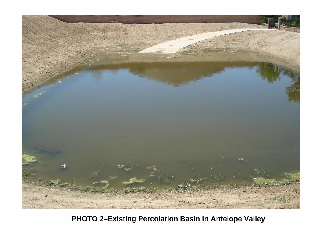
PHOTO 2–Existing Percolation Basin in Antelope Valley

PHOTO 3–Test Basin Excavation

PHOTO 4–Five Foot Diameter Stand Pipe

APPENDIX

I. :
':
('...:DEPARTMENT OF PUBLIC WORKS
M E MaR AND U M :.'
TO: Carl L. BlumAssistant Deputy Director
October 24, 1986'
FRDM: Rod Kubomoto
~~jO Drainage & Grading SectionANTELOPE VALLEY INTERIM DRAINAGE POLICY
Recoimendation ~.:'~
i.'"
Approve the attached interim drainage policies and design criteria and standardsfor implementation in the Antelope Valley.
. .
. .
Discussion
Interim drainage policies for the Antelope Valley are a practical approach toflood hazard mitigatiqn until regional drainage improvements are installed. Inlieu of a moratorium on new construction, the Board of Supervisors adopted aninterim drainage policy ()n October 28,1980 for the Quart'! Hil1 area (seeattached copy). This wa~ necessary due to an increase in development pr6posalsin this' area which lacks drainage conveyances and adequate outlets. The deserttopography, coupled with the lack of well defined drainage courses and existingimprovements affecting flaw patterns, compounded the problem. Regional drainageimprovements win ultimately alleviate the unmet drainage needs. However, inthe interim, the main concern was and is today to allow development to occurthat is free of flood hazard whi le not significantly worsening floodingcon"dttions to' adjac::nt properties. The Quartz Hill policy essentially providedthis goal by collecting and percolating the increased run-off due to developmentand requiring elevated building pads above the anticipated flood level.Development continues to increase throughout the Antelope Val1ey and similardrainage problems are new being experienc::d. The Quartz Hill drainage policy isa reasonable compromise for the entire valley floor until regional facilitiesare installed. . Attached are guidelines relative to re'lie'iiing and imposingrequirements at tentative map processing and design criteria and stand~rds forproposed County maintained drainage facilities. Approval of the recommendationwill assist staff in regulating reasonable flood plain management for this areaand improve section plan review consistency.
.'':''-.

". "
j -'.i ':
\~/ELOPE VALLEY MASTER DRAINAGE PLAN FEES
In order to provide a source of funding for regional drainage improvements, the
Department has adopted drainage fee requirements for all new land divisions.
The requ i remen ts are as fo 11 ows :
$ 2.000 per lot for single family residential
$10,000 per acre for commercial, manufacturing, or industrial
$1,000 per multi-dwelling unit (condo and apartments)
$10,000 per acre for mobile home parks (condi tioned at time of CUP review)
These fees are currently waived for condit)onal certificates o~ compliance and
building permits. Lots within a proposed land division with existing dwellings
or other permitted main use are also exempt from the fees.
The developers must enter into' an agreement wi th the County and provide adequate
.Jrety for the fees wh,er(,(a) they apply for occupancy, or (b) the County has"'
indentified projects for construction which will use this money,' Based on,
current cónstruction scheduling of regional facilities, the fees shall be
collected prior to land division recordation. The submission of appropriate
security shall be in accordance with Government Code Section 6õ~99 and approved
by.the County, Two signed originals of the agreement are required and the
surety shall be in the form of cashiers check. letter of credit, or letter
of assignment. Due to the lengthy process to exonerate bonds, the Division
does not prefer this form of surety for fees. It is intended that the Antelope
Valley Master Plan of Drainage Facilities be built as soon as funds become'
available. However. if the funds are not used for construction within 7 years~
the funds. if collected, will be returned to the applicant.
'-
:.t...~

r " .t, . ~
OR~ rNAGE BENEFIT ASSESSMENT AREAS (DBM)..'.'-
Proposed County-maintained facilities outside of the Flood Control District
boundaries require maintenance provisions in the form of drainage benefit;
assessment area administered by the County and funded by lot owner assessme~ts.
The formation of the assessment area is coordinated through the Planning
Division. Due to the relatively long process to legally form the assessment
.area, the developer may elect to enter into an agreement with the County. This
would a110w him to record the land division prior to assessment formation
provided that no lots change ownership (see attached copy).
The following data must be submitted to the' County to begin processing the
assessment:
1. $3,000 processing fee
2. Land division map.. ,\~,~" \
3. Copy of the privatè drain plans.,
, ~ ¡
4. Benefited are indentiried
5. Anticipated annual maintenance cost
6. 0 & M manual for multi-use flood recreational type facilities
7. Agreeme!1t
DETAILED PROCEDUR~S ARE OUTLINE0 PER SEPARATE MEMORANDUM (SEE ATTAC~ED DRAFi
COpy) .
TE~TATIVE MAP REQUIREMENTS
Tentative map reviews are to be e~aluated per current guidelines and procedures
consistent with the Subdivision Ordinance. However, the added conditions are:
. "'. .

.. ..
Assessment of required master drainage plan fees.
c
2. Formation of a benefit assessment district to fund the maintenance o~'
drainage improvements (P.O.) if the site ,is located north of Avenue liS",
Township 5 North (Outside Flood Control District boundaries).
3. Execution of the necessary agreements for master plan fees and DBAA formation
and deposits prior to land division recordation.
.
4. Dedication of right of ways indentified on the Antelope Valley master
.drainage plan. Market value of the right of way can be used to offset the
drainage fees. Construction in "planned flow pathsn will be restricted but
right of way will not be dedicated to County.~~'"'" '\.\
,
i¡i
,-
..'......

....."', ..
DRAINAGE CONCEPTS
Review of drainage concepts are to be consistent with current requirements and
guidelines. However, four key issues should be acknowledged by the consy1ting
engineer to avoid future complications and possible significant expenditures.
1. A max imum of seven
retention basins.
revi ew.
day soil percolation rate for delta-volume and/or full
A soils report should be submitted for soil section
2. Drainage solutions that not only mitigate the flood hazard to lots but
are compatible with street safety drainage requirements (refer to Road
Sewer and Water Section).
3. location and approximate sizing of the percolation bas in.
"'" ',..,
4. Need for drainage ~cceptance letters from affected adj acen t propertyi
¡ ~ iowners.
DESIGN CRITERIA l
The interim drainage provisions for the valley floor require subdivisions to
limit drainage outfloiy to the before developed condition quantities. This would
include not only the change in peak Q but also the volume due to the incremental
de:~ease in permeability associated with development. Faciliti~s therefore must
detain the change in peak Q and percolate the change in volume to satisfy the
interim policy. Percolation basins are the preferred design concept. However,
due to site topography, public opposition, and field design parameters, several
design options may be considered acceptable.
......

1~~ \:' l'
:;."
. ';1. Allow contributory drainage to flow essentially through the development
and detain the peak Delta Q and percolate the Delta volume. Return
discharge of flows to the predevelopment condition or obtain dr,inage
release letters from all affected properties.
2. Allow contributory drainage to be collected into the basin with the
developmental increase and regulate outflow to the before-development Q
while still percolating the Delta volume. Return discharge of flows to
the before-developed condition or obtain drainage release letters.
3. Allow only detention of the peak Delta Q provided there is a reasonable
adequate outlet and drainage release letters obtained from all affected
propert i es.
~,,~'- '....,
4. Provide full retentJ~n and percolation of flows.
Each site must be evaluated on a case-by-case basis and drainage release letters
may be mandatory due to the particular circumstances. Existing public roads
maintained by the County may be considered as acce?table drainage oultes provided
Departmental approval is obtained.
Interior street patterns should be designed to ac:ommodate existing drainage
patterns and street sump conditions should be avoided. Local streets can be
utilized to convey storm flows provided it complies with street safety drainage
requirements (refer to Road Sewer & Water Section).
I',,
.,"-. ,

, "
, r.'" . (' ~
P~RCOLATION BASINS
A. HYDROLOGIC CRITERIA
Basins are to be sized on a 25-year rainfall frequency, 4th day only, storm
event plus one foot of freeboard. The volume analysis is deemed acceptable
due to physical conditions that indicate that the area experiences high-
intensity, short-duration (thundershower) storm events. Updated methodology
and hydrologic criteria are being evaluated by Hydraulic and Water
Conservation Division. Analysis procedures and updated data will be
incorporated upon Department pol icy and 'im~l ementation approval. , .
B. GENERAL DESIGN STANDARDS
Provide adequate energy dissipation for inflows to prevent scour and erosion
'~"of the basin invert 'and' side slopes.
. ., ..,
Provide, standard protection barriers and trash racks for inlets and outlets.
Provide a secondary overflow path (i.e., acess road) to a paved public street
as an auxiliary spillway.
Outflow lines (except true detention type basins) are to be elevated a
minimum of one foot above the basin invert.
The basin floor is to be graded to drain away from the outflow line (i~ ',.
typical). This is to be minimize basin maintenance by isolating and
concentrating summer low flaws.
".. ...

. .. ~ : . ."
No seepage pi ts in the basi n floor to mitigate nuisance flows wil 1 be
allowed due to their high maintenance and lack of reliability.,': ;;
c. STRUCTURAL CRITERIA
Soils report should be submitted that addresses slope stability, effects of
rapid drawdown, infiHration, potential seepage. and possiblc effects such
as land settlement or increased lateral infiltration and groundwater
recharges.
Provi~e maximum 3:1 side slopes unless the soils report can verify stability
at steeper slopes.
. '
I '
I\'-
Basins utilizing walls as a means of retaining water must be reinforced" "
concrete and strùcturally designed for hydrostatic pressures.¡,¡ ;
"
D. ACCESS AND FENCING
Provide security fencing and a double drive gate per Standard Drawing No.
2-D 178 or provide Department approved blockwalls (Min. height of 5 feet).
Provide a 12-foot wide minimum concrete access ramp to the bottom of the
basin. Maximum grade into the basin shall be 12 percent.
Provide a 5-foot setback from the fence line or wall to the top of the basin
slope along the basin perimeter adjacent public streets.
..'"
'.~ .. . ..
"
,. ' ,', ..
Prnvide an 8-foot setback from the fence line or wall to the top of the basinI
~ .ùpe along the basin perimeter adjacent private lots. Lesser setbacKs must be
approved by the Department1s Soil Unit and Operation and Maintenance Division.
RIGHTS OF WAY
The rights of way sha:l be shown and properly labeled on the plans. Basin
facilities located outside the Flood Control District boundaries shall have
easements dedicated to the County of Los Angeles for Flood Control purposes.
Basins within the District boundaries are to be dedicated to Los Angeles County
Flood Control District for flood control purposes. Rights of way in fee simple
is required for facilities within future right of way needs per the Antelope
Valley Master Drainage Plan. Planned flow paths are to be considered flood
. . .
. .
hazard areas.
\
'.," \~,.
¡.t ~ i
'.-.'", ...

...
..; .i -,. i ('. , ~'.f.,
3/81
\
I:-TERHt STANDARDS FOR PERCOLA TI ON BASINS
1. The basin capacity shall be the difference in volumeof runoff between the undev~lcped subdi vis ion and thedeveloped conditions for th~ fourth storm day usingthe modified rational method. ~
. ~J,ri ,.1"fIll c: Ø'
~~ot '7 ~~J,~ .2. The basin's side slopes shall not exceed one. vertical to four feet horizanal wi th a depth. ponding no greater than 2,5 feet.
3. The development shall be designed to direct nuisancewater to the basin.
,, .
4. Basins'must be designed to totally ~~rcolate drainage,within a seven day time interval after storms.'Percolation test~ will have to be provided arid approvedby County Engineer. A controlled discharge outlet will'have to be designed if soil conditions do not allowadeq~a te percolation,
S. The basln de sign should be such tha tit doe s not advers ely,", affeci:,"the aesthetics of the area and all efforts should
be made t,o :preserve significant natural'plants and trees.tt ~p.p.
._ '0. The subdh'ider shall establish a houseO\.¡ners as~ociationfor the ~a in tenance for al 1 dra inage facil i ties 0 therthen those accepted for maintenance by the County. "
.~
,.
"'
. : ~

\.~__..o,_.. .__.._._._( .. ,
. ~""~'''. . \ ." :':... ..
,
\.:;
'-
.. .
,.
.-- (:: J.UNTY ENGINE¡:R.FACIUTiES
~IT¡J '. R:c~ - 5pa-;c/ a:
MOilON B '' SUPERVISOR BAXTER WARD
October 28, 1980
..,.
n~Q?
.-: .. ... I'.. ~ .. t'f~,. . .....: .
, ,
"-'.'- ", ,
, ,
f Supervisor Ward for Interim Drainage
s suggested by North County Citizens
".
r~'.?~"~..--/.,."" 0.. ;0" .~- '~: ':r"_..,~r'....:;.. 'pi'.,',,,--' ,,. ,;.;1. .,.:.=:::... ..1..
-- .~:...~.. .'~",.,.Irrr," ,~
"
. '. . . "
ADOPTED .'BOARD Of SUPEiNISORS
COuitrr OF LOS AtlûëlES
4 0 CT 2 8 1980
JJ ¿~~1/'... IJAMtS S. M1~
txtcuriv£ arnC"
",
.t
, ."....

~, Ii__ "'~ . ." ~' . , ¿It ~.--,~. ':.,'f. : '\ '.
MOTION BY SOPER VISOR BAXTER WARD,\"'.... October 28, 1980
..
. .
The Quartz Hill area. of Antelope Valley is locat~d on arelatively !lat gently sloping plain which can be identified with the
large alluvial plains lound at the bases of most mountain ranges. .Typically, storm runoff over th~se areas take the form of sheet flowwith few defined drainage courses. In rcc~nt years, however, thearea has begun to develop into ~ residential community at an "incrcas-ingpace with a corresponding increase in the total runoff. Thisrunoff has been confined to 'unimproved shallow drainage paths or' ".concentrated and chånnelize.d in thé streets. These streets,
:,: partic:ularly in the northsouth direction, have insufficient capacity to _ _ ~ ,~'. .' ,; contain t his runoff and adjacent properties have been subject to . _ '. ,'. "'.
, '!looding. The area also has many unimproved dirt streets that Dot _ _'only erode in storm !low, but could become a probl~m vw'ith a constantflow of nuisance water crossing from new developments upstream.
,~ '-,The area 1ìà.s' limited topographic data and the ,extent of the
flood hazard area is :difficult to deterrnine as the terrain graduallyflattens toward the valley. The area. needs a comprehensive studyoùtiÙiing the problem areas and suggesting sålutions. An inferimpolicy must be established to allow development to continue until ad etail,ed master plan for drainage is completed.. .,
The proposed int~riI: policy incorporates many of therecommendations by the North Cou."1f:i- Citizens Planning Council aspresented in its lettér dated September 18, 1980, to Our HonorableBoard.
THEREFORE, I MOVE TEAT TilS BOARD:
1. Establish thë attac::ed interim policy fordrainage of new dc\'elopment in the QuartzHill a.rea. .
,.2. Instruct the Cowity Engi.neer to determine
the extcnt of the flood hazard and. preparepe rmanent policy a.nd maste r plan fordrainage in the Q~artz Hill a.rea. '
. ,;..-.
,
¡
~d
¡
Ii
!
i:
~ ;
.1
, 'j
I,
l, 'L ~i
t'--,-
~.,
rt. "'.~ .~I
i
Iii
I
I

-".. ...-_'"... ok......~... ' !"
. :'t.
,.
, .' t -. . if'- . ,
INTERIM DRAINAGE POLICY FOR
QUARTZ HILL AREA
,
I?eve lopme nt will be pc rmitted outside the' flood plain.
Developments ''\vithin 'the flood plain may be allowed if the street
design and development layout do not alter the natural drainage pat-
" terns or adversely affect adjacent property. Floodways or flood,. .'
protection areas must be provided for the passage of storm waters.
i,. .-- .' '. " .:'~'...'
. _Fully improved roads r.ay be used for routing storm water
runoff. When the design sto rm exceeds the carrying capacity of the. .,." ,,-,'street, in ncw,dèveloi;ments, £1oo¿\vays, or flood protection district
. . ;ì
. ,
shall be established.
Vrhen it is determined by the County Engineer that the
development will have a signific,:nt i~c:-ease in runoff and that this
inc.:ease will 'adversely affect downstream developed areas,
pe ::colation basins may be required to detain the in~:.cased ru.:off
caused by the developrrent. Requirements for these basins shall be,-
established by the County Engineer.
........

. . .. "oJ" .~.
'f!
'-.PROCEDURES FOR
DBAA MAINTENANCE AND TRANSFER
During the past few years, the Land Development Division has been requiringmeasures be taken to provide for drainage in the Antelope Valley by o~~sitedetention or retention of increased storm water developed by the new sub-divisions. The method used has been minimal storm_ßrain systems which outletinto' a basin. These basins are designated to accept that portion of runofrattributed to increased development. This policy was adopted by the Board ofSupervisors on October 28. 1980, as an interim policy for the Quartz Hill area.of the North County. Since all of the Antelope Valley has similar drainage con~cerns in areas other than Quartz Hill. the policy has been expanded to includesubdivisions throughout most of the. Valley.' .
There have been several subdivisions with requirements to install percol ationbasins to provide for drainage. The developers have also been required to forma drainage district to maintain these systems since those formed are not withinthe Los Angeles County Flood Control District boundary. These districts arecomposed of the properties within a subdivision and are formed under a benefitassessmènt area with money to be collected with the individual tax bills. ..Maintenance is the developer's obligation until these facilities have beenaccepted by the County. Additionally, ÐBAAs are being formed for subsurfacedrainage systems to collect water in geolo~ical problem areas. These systems,called hydraugers, are located near Valencia.
, l
. ,, ,
~ .. "Procedures are as fol16~s:\~ " " II " .
The Land Development .Division, as part of the subdivision require-ments, shall process the plans, collect bands, help establish the BAAand 'determine when the work is complete. When the work is complete,the Land Development Division shall recommend acceptance of the workand provide Planning Division ~ith the information necessary to set upa procedure so that maintenance may commence.
Among ne~essary procedures are the following:
Set up fiscal collections from the Auditor-Controller.
Recommend yearly adjustments of collections to the Board ofSupervisors. 'Develop standards and specifications of maintenance or modifythose submi tted.
1-
2.
3.
4.
S.,.
6.
7.'" ',"
Monitor facilities.
Develop maintenance schedule.
Develop a disbursal program in conjunction wi th Business andFinance Division.
Development of work contracting.
..., "

"
. ~"~ ": l' I"f"
°roceduresi'age 3
Business and Finance Division
1. Establish recordkeepîng procedure for c011ections and disbursalof funds .:. , :.. , ,"
. Flood Maintenance Division
, . 1. Receive work assignment from Planning Division including:- a., Copy of BAA Ordinance. 'b. OBAA document
c. Subdivision map'-.' d. Construction pl ans '. ,'. e. Operation and maintenance manual or specif5cations (as, ,required),
Create work order. ' , . ~. ',; .. -. ~ ...;;.. ...: Recordkeeping, fundi on, time and cost.. :Servicecontract development.August budget estimate to Planning Division (each year).
. : :~"
- "
. 2.3.
.-' 4.5.
'-, " ~. ,"", .
, Construction Division.,'-...' ".. . .
\, 1. Provide ongòing inspection during construction.2. Provide final i~~pection prior to acceptance of consttuction., "
The Dràinage Benefit Assessment Area listing is attached.
KC:-: acm(8.1/3)
,.
"
-., .
f' ,,' . .
: i~ ,

.....~'I ~'_
. ~.. ',. . I . t
Procedures"'Page 2
\ :'-/
'1-2.3.
4.5.6.
." 7.
8.
9. .
1 O.
land Develocment Di vi sion
Identify drainage ne2ds on tentative.ma~.conditions.Review canstruction plans.Send construction plans to Flood Maintenance Division for reviewand maintenance estimate.Collect deposit for OBAA formation.Send material for D6AA for~ation to Planning Division.Approve construction plans~ . . ".Construction inspection by Construction Division.Notify Planning Division of completion of construction when Boardof Supervisors' letter is prepared. ' .Recommend acceptance of compl eted construct ion by 1 etter to Board
of Supervisors after maintenance tax is collected. "Transfer maintenance apackage" to Planning Division.
.
. ",":"';,::;:, .,,~::.'?'.;;":'.::.::': ~:-- -,..., , ,'-~ . - '~ ::.:',,~ ''':.','':::,-.." - " .~ :'~:.::: PL anni ng Di vi s i on - ":.: :':~' . :',. ", '. ,
. ...... ,.'-. '.... .:..... ...... ':." - .... ." ~~ '. 'j. .:, .'. "." .' '- - ,...
. " "
,.
.
-....._...__... -~-.._.. _..'
.1. 'Accept OBAA formåtion materiala. Jab number access (53,000.00+).. b. Subdivision map ,-c. Ca~y'of private drain plansd. Benefi ted area boundarye. Maintenance cost estimatef. Operation and maintenance manual (as required)
Prepare report, EIR, Resolution Instituting Proceedings, andNotice of Hearing and Filing.File necessary documents with Board of Supervisors.Post Notice of Hearing and Filing. .Submit notification affidavits.Prepare resolution determining assessments and submittal tovoters.File resolution determining assessment with Board.Notify Land Development Division when DBAA is formed.Accept transfer package from Land Development Divis~on including:
a. Copy of BAA Ordinanc;b. DBAA documentc. Subdivision map and assessment rolld. Construction planse. Operation and maint~nanc= manuals or specifications
(as requ; red)Records for each area.Notices to Business and Finance Division.Assign work and disbursements to Flood Maintenance Division.Budgets each August for Board of Supervisors' approval.
. ,
2.
3.4.5.6.
7.8.9.
10.11.12.13.
-. ...'.

... " pro. ,.' !., *' .
:: DEPARTMENT OF PUBLIC WORKS
MEMORANDUM~ ,
TO: Mi ke NagaoPlanning Division
Septembe~- 5, 1986
FROM: Carl L. BlumLand Development Divisioñ'
",:..
-, '
. .
File No. 2~i5.40 -~. .':Transfer of Storm Drain Systems ,,:,Drainage Benefit Assessment Area No. ..Private Drain No.
For your information, the above~referenced Retention/Detention Basin and StormDrain System has been transferr~d to the District for operation and maintenance.
..-:;.;.. 1,. ~..-.. .: ,. ,"
'f :-.
Date of 'Board ,of Superv~sor~,~ ,åPP,roval: , ,. ...~e.. ..... .~¡~. ~ .:..:;.~-: ,.' u, _" :0. :, :-
.' Date of Board Letter:' .,:"", ~ ~.,' , ".~' . _ (copy attached)
.. " ., -., ... ,
.
. . ., .
Supervisorial District: 5 _. .._... .' - "
'.Desi gned by:
Basin Capacity:
~'''.. ~
. .
, . -
a.cr~ feet.
Main Lipe Storm Drain Length:
Area:
feet more or less
Thomas Guide: page
Quad Sheet:
Operati on and Maintenance Area: Hansen Yard
Rod H. KubomotoHead, Drainage and Gradi ng Section
RHK : amc
Attachment
',- .
bc: Contract Administration Division, Operation and Maintenance (2), (Hanseo.Yard), Property Management (Permits), Land Development (O&G), Secretary ofNomenclature Committee, General Files.
'. ,

"..L...,e.. .1' . ". .i" .. .j. , '
, .......
\.-:...
"
'.
. 6
7
~
8
9
10
11
12
13
,.
DRAINAGE BENEFIT ASSESSMENT AREA
No. Name Location
1 Tract 38994.P.O. 1706
Avenue L-8Street West.I... . .'.. .. .' . ".
.. -. .... . ~ -, . ..2 , Big Rock Mesa': -, Mal ibu
" .. ',' .." .. . ~'. .. ,. .~:.. .'........ ....
" ... . ..
3 Tract 36496 . '~, ',' Canyon Country.. '.' .... . ,':. ~. ,'.: ..,:,;: '. ":" ..... ..,
4 'Tract 30114 .',' .:' El i zabeth Lake. ~':',_P :~'_ ~~48 -,'.::::.~:,',,::.~:;.r'.::.' ::'" '.,\ ,:._ . _ ':.";'
5 '. Tract 36395 . ~~: '::: Avenue M-8 and
p .D. 1853,,:,'_~j;,",. 60th Street West. ":." ,'... ..' ',.. ~ - ~ -~..)' ',,:.é .' .. ".:' .J . ... ", ... ,.- .. ~.... .... .... ,,'' ':. . . ..
. Canyon Country(5 i erra Hi ghway)
. '
',Tract 43528 .. .,:
P.M. 13213 Avenue M andP.O. 1809 ,,, "';, 10th Street West
..Tract 43545 i' Avenue K and 45thP.O. 1937 'Street (W.)ìract 44330 Quartz HillTracts 36875 Avenue R-12 and& 43087/P.b. 1990 47 Street E.
Tract 44370 Division Street andP .0. 1980 Avenue R-8
Calle Del Barca Malibu
Tracts 43708, 40th Street W. and44440, 44441~ and Avenue L-844442
Type ofMaintenance Con~tructed
Sump/Landscape 20~ ConstructedFormed
.. ... .
Hydraugers No Cons truct i onNot Formed
" . .'. .....
Hydraugers ' Construct i on. , compl eted-Formed
Storm Drain No ConstruCtionFarmed
,- .. . .
. .
,Sump ..
~~~~~~'~:~;-s .',. ,.
Construction_' comp1 eted-Formed
Formed
. '
Dry S.D. 85% ConstructedVoted
Sump No ConstructionNot Formed
Sump FormedSump Abandoned
Detention Basin Not Formed
Hydraugers Voted
Sump Not Formed
'..-. ,

, ,. ',,~~.
i ,¡OM..S A, TIDEMANSON. DlrrC10rCECIL E. B UGH, Chi,r D,puiy Dlr"lor
MAS NAGAMI, Aulll.nl DlrrC10r
TO:
FROM:
COUNTY OF LOS ANGELESDEPARTMENT OF PUBLIC WORKS
900 SOUTH FREMONT A VENUEALHAMBRA, CALIFORNIA 918003-1331
Trlrphonc: (818) 458-5100
j
October 25, 1989
Land Development AdvisoryCommittee Memb~
Donald L. Wolf~ ~ifAssistant Deputy DirectoLand Development Divisi n
INTERIM DRAINAGE POLICY
ADDRESS ALL CORRESPO:-OENCE TO:p,o, BOX I~O '
ALHAMBRA, CALIFORNIA '9U01,J460
IN REPlY PLESEREFER TO FilE:
Attached is a draft interim drainage policy and guidelines
for land development proj ects in the Acton area.
comments are requested by December' i, 1989.
JEE:mg(M-2)IDPL-Q
Your

"
I DRAFT JACTON INTERIM DRAINAGE POLICY AND GUIDELINES
The Interim Po l'i cy;
Containment of the incremental increase of runoff and nuisance flows from landdeve 1 opment proposa 1 s with in the wa't~.t;S,J)édfO r dQwñt'Ø:w.õ; AbtÓh.;r
Tentative Map Requirem~nts '
~ . . :....., ..Tentative map reviews are to' be evaluated per current guidel ines and proceduresconsistent with the Subdivision Ordinance. Drainage concepts will continue tobe required and tentative subdivision maps held until the concepts are approved.The concept review will include an intensive evaluation of the lot layout andstreet patterns, as it affects draïnage patterns and public safety. Thereduction of proposed lots and/or redesign of street patterns may be necessaryto mitigate the drainage concerns (and. thereby avoid certain structuralimprovemen ts).
Drainage Concepts
A drainage concept will be required for any division of land in Acton involvingareas of known flood hazard and/or five acres or greater in total area. Delta Qbasins shall be 'utilized to contain and percolate the incremental increase inrun~ff due to the development, similar to that used in the Antelope Valley.
Review of drainage concepts are to be consistent with current requirements andguidelines. However, several key issues should be acknowledged by thedeveloper's engineer to avoid future complications and possible significantexpend Hures.'
1. A maximum of seven-day soil percolation rate for delta-volume arid/orfull retention basins. A soils report should be submitted for soilsection review.
2. Drainage solutions that not only mitigate the flood hazard to lots butare compatible with street safety drainage requirements.
3. Location and approximate sizing of the Delta Q basin.
.4. Need for 'drainage a"cèptance letters from affected adjacent propertyowners.
5. The existance of multiple watercourses in the developed areanecessitating multiple Delta Q basins.
6. Preliminary hydrology studies to evaluate before and after runoffconditions for the on-site areas as well the contributary off-sitea rea s.

" . I ~. 1
"
-2-
Drainage Concepts (Cont'd)
The drainage concepts will be coordinated and concurrently approved by both theDrainage and Grading and Road/Sewer and Water Sections.
Des i9n Criteria.I
The interim drain-age provisions require subdivisions to limit drainage outflowto the before developed condition quantities. This would include not only thechange in peak Q but also the volume due to the incremental decrease inperneabil ityassociated with development. Facil ities, therefore, must detainthe change in peak Q and percolate the cha'nge in,volume to satisfy this policy.No credit shall be permitted (in determining basin volume) for percolationd u r i n gin flow. 'Percolation basins are the preferred design concept. However, due to sitetopography, public input, and field design parameters, several designoptions may be considered acceptable including:
1. Allow contributory drainage (with debris) to flow essentially throughthe development and deta in the peak Delta Q from the deve loped area andpercolate the Delta volume. Return discharge of flows to thepredevelopment condition or obtain drainage release letters from allaffected properties.
'2. Allow contributory, desilted drainage to be collected into the basinalong with the developmental increase and regulate outflow to thebefore-development Q while still percolating the Delta volume. Returndischarge of flows to the before-develop~d condition or obtain drainagere 1 ease 1 etters.
3. Allow only detention of the peak Delta Q provided there is a reasonableadequate outl et and drai nage rel ease letters obtai ned from all affectedproperties. Percolation of nuisance flows is still required.
4. Provide full retention and percolation of flows.
5. For subdivisions of five acres or less, provide drainage release lettersin. lieu of a Delta Q basin.
.Each site must be evaluated on a case-bY-case basis and drainage release lettersmay be mandatory due .to the particular circumstances. Existing public roads
'maintained by the County may be considered as acceptable drainage outletsprovided Departmental approval is obtained.
Interior street patterns should be designed to accorrodate existing drainagepatterns and street sump conditions should be avoided. Local streets can beutilized to convey storm flows provided it complies with street safety drainagerequi rements.
Basins are to be located at the downstream end of the developed area to maximizeinterception of nuisance flows and peak flow reduction.
:"3-
I DRA.FT 1Road Drainage Criteria
The attached charts depict the criteria for mai.ntaining road drainage in theinterim policy for,Acton when storm drain solutions are not feasible. Thispolicy permits flooding under certain conditions of all roadways up to a 25-yeardesign frequency rainstorm. .Rights-Of-Way
, '
The rights":of.-way shall. be shown and properly labeled on the plans. Retentionand Delta Q basin easements are to be dedicated as flood control purposes to LosAngel es County Flood Control Di stri ct.
Design Standards for Delta Q Basins
A. Hydrologic Criteria:
~~~~~~~:~t~~-~nre~~~f//~ãr~âei~~~fr=C~~~~~~f~~~~i r:~:J~)'-",( hydrology before and after on the developed area without consideration ~~~\ debris. .___"_-_.".-'......._.,___ø._...__ n _..-__M ___--.."'____...~_
B. General Des~gn Standards:
Provide adequate energy dissipation for inflows to prevent scour and erosionof the basin invert and side slopes.
Provide standard protection barriers and trash raCKS for inlets and outl ets.
Provide a secondary overflow path (i.e., access road) to a paved publicstreet as an auxil iary spillway.
Outflow lines (except true detention type basins) are to be elevated aminimum of one foot above the basin invert.
The basi n floor is to be graded to drain away from the outfl ow 1 i ne(3% typical). This is to be minimize basin maintenance by isolating andconcentrating summer low flows.
C. Structural Cri teri a:
Soils report should be submitted that addresses slope stability, effects ofrapid drawdown, infiltration, potential seepage, and possible effects suchas land settlement or increased lateral infiltration .and groundwaterrecharges. ,Provide maximum 3:1 side slopes unless the soils report can verify stabilityat steeper slopes.
Basins utilizing walls as a means of retaining water must be reinforcedconcrete and structurally designed for hydrostatic pressures.

('. ', '. '
-4- IDR/\F1lD. Access and Fencing:
Provi de s,ecurity fencing and a double dri ve gate per APWA Standard Draw~ n9No. 600-0 or provide Department approved blockwalls (Min. height of 5 feet).
iProvide a 12-foot wide minimum concrete access ramp to the bottom of thebasin. Maximum grade into the basin shall be 12 percent.
Provide a 5-foot setback from the fence lin~ or wall to the top of the basinslope along the j:åsfnperim~ter aajacent ,publJc streets. .. ~ :...~. . .Provide an 8-foot setback from the fence line or wall to the top of thebasin slope along basin perimeter adjacent private lots. Lesser setbacksmust be approved by the Department in advance.
Drywell Alternatives
In smaller residential subdivisions (particularly with large rural lots) the useof a Del ta Q basin and associated interceptor systems may be impractical. TheDepartment will consider the use ofa Maxwell Type iv drywell (or approvedequal) on a case by case basis under the following conditions:
1. The subdivision is ten acres or less with minimum lot size of two acresand cannot be resubdivided into smaller lots.
2. Runoff and sumner nui sance flows are properly intercepted and drjwell sare designed to handle potential debris laden flows.
3. Soils analysis supports the viability of operation," including in areasof proposed fi 11.
4. The drywells are located within pUblic easements wHh paved vehicularaccess provided for maintenance and' repair functions.
5. The use of the5e faci 1 i ties have been adequately addressed in theenvironmental document for the tentative subdivision.
6. The approved hydrology study indicates a minimal increase in runoff dueto development.
, 'In certainsituabons, it may also be impraCtical to desi1t all tributory flowsand still pick. up clear, developmental runoff for a Delta Q basin. TheDepartment will consider, on site specific basis, the use of drywells to achievepercolation while allowing dilluted debris flows from the developed area toenter a Delta Q basin. It is the responsiblity of the engineering consultant todevelop a basin facility that can operate in the dual capacity function.Drywells will be considered in controlling summer nuisance flows whereintopographic features and other Department policies and standards do not allowthe practicality of draining the flows into the Delta Q basin.

1I~ I tl~lll K\.U UVI! ,'..~ "'"" L- " I "' ""
AC
"' -
"J
--'.
--CCIG' ffITfIA
limo
FLO
JOIN
:; C
JOIT
lÜ'
OJ'
!'IE
N"
FUL
RQ
Q I
MfO
YB
'EWithin Gutter
Are
art TERMT 1 VES
Q25
QlO
o X V
Hi g
lway
S tree t
PíE
SWr
1. W
i tlio
ut s
oonn
dra
inX
Less than 6
t fre lane
R/ to R/W
OU
TfI
Affs t be o¡:r
or be 100
1 n
each
eith
er s
i æ
dire
ctio
nof R/W
X*
One free
* .
lane must
"æ o~n in
.each direc-
'.
. ,
tion
2. I
ii th
sro
nn d
rain
Xless than 6
l free 1 ane
g;Q
The
re a
rr~
gene
ralll
no~
istin
g ac
ceta
ble
rrs
t be
cpr
1 teri a
outlets or coc.n ra flo,,
in e
ach
,ço
vem
sdi
rect
ion
'.:
X*
Or
free
lane
I1s
t be
' "
..", .
.. .
opn
in e
adi d
) re
ctio
n
pi.. h
R'Y
/
5' 8
'- (
, 4' I
' '
"
1c ~ leri a
ÇJv
ems
'511
26&
1, R/,.
~- s
a', 6
i;~~~
rx P
ree
101,
£(12
): .
t/QoJ
Q"
\lh ' " n..J Qii .
Rid I i ,I i1
iI: .11
" "
,I II
I i.
,\_..~ - _,. .. .510("' cI,.";,,
---
-ì ,.
-.. ,/
.,;; "
;-IC
HW
4'!
,.. i. .. ...
. -"
:'",~":.: r S r0011 drA:"
. -.. '.
0 -~ ..U "" p!...
::-,
""!
r-j
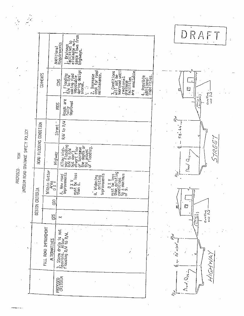
ffCFSEO, lON
11'R
IH R
OA
D ff
INA
-E W
EE
PQ
lcy
"
C£S
IG"
CR
ITE
IARO FLOODING CODITION
OJ1
'IEN
rSFLll R(W I¡.O\I
Within Gutter
"N
'ea
I\ld it i aiia 1
PL T
EM
TI
VE
025
Qio
D X V
Hi r
jway
Str
eet .
.m
osC
OS
Rcq
ui r
Elf
0i ts
ffC
PSE
Or' Stann drain is not
XA. Ne, road
Allow iiit-
R/W to R/W
Roa
ds a
re1. Flooding
1. o
rain
afO
OIT
EH
IAea
sib1
e. A
l1u.
'ir
rrov
8lB
1 ts
¡m f1
oo' i
ngfu
llyRI to R/W
façi
l Hie
tof1
ood
i ng
RlÌ
ta R
/W.
J to R/W
impr
oved
iil: i
ng
road
ehiiinilte nui-
D X V
wt d
m r
t,ifTilSSab 1 e
S1\
ce f
Jo,s
fran
' '
rrst be less
di vert fl (M
c1ur
i n9
des
i gg
hi Ç
h1tly
$.th
an 6
.or increase
stan
ns,
the
dept
ll or
'.tile amun t
.~','
of flooding.
2. lnvease
:cos t or roa,d
8. Widening
iæin
tena
nce.
ex;s
tin~
irrr
oV8I
En
s
D X Y
3, ycxditions
rrst be ess
wiJ rrt~
than
exi
s ti
ng
iiior
oved
un
t ico
nditi
ons
Jeqi
onài
to a
mai
mLI
ra 1
nçç
llof
9.'
facili ies
are
avae
"
4. Possible
aclit
ionç
çllia
bilH
ies.
"
P.i.v Ii , . ~
I d,.d
, Qis
'
, RI.,
J 'i
80 ,ripc-+ i I
Riw
'
. I ' ¡ lio
d Q
"
, RlvI
tf -
5'6
:&¡/
~
¡
0 :: b - 11 ~H
i G N
'' A
. 'I
S1R
GG
1
. .. t . :"
:: :

:'1
! i t !
'ffcr
SE
D .
i:NINTRIM R() mAiNAGE SAET PQICY
. "
C£
I G"
OU
TE
IAR
Q F
LOO
DI!\
ffD
ITIO
N~I
EN
S"
FU
L R
04 If
fffV
EJO
OWithin Gutl:r
Are
aH
i qjM
ayfi
di ti
mal
' fJ Tft' TI YES
025
QlO
D X V
Stre
e t
mas
ins
Req
uire
rets
ffC
PSE
D~. Stann drain is not
XA, New road
Allow hit-
Not
()P
P ly
Roa
ds a
re1. Flcoding
1. Ora i nòÇ3
mIT
fIA
feas
ible
.E
xcee
irrr
ovee
ents
wÆ
í fl c
o i n
gfu
llyRJ to RfW
f ()c
i 1
i t 1
e s
to 1
J 1
m i
-fl
cod
1 ng
R¡W
to R
¡W,
R to R/W
irrr
oved
flak
ing
road
nate
nui
san
ce lo
wD X V
rut don i t
irrp
assa
ble
fron higM'Bys.
nust be 1 ess
divert flÛÛ1
dur;
ng
desi
ggi "
. ' ,-
than
6.
or increase
s to
nn .
the depth or
,"
õTun t of
2.' I
nlre
ase
': 2. Pipe or
, Cox cùl-
floo
ding
.co
s t '
or
road
vert or Ar 1 zma i *
B, W
iæni
ngnB
i 0
ten
ance
.ty
p cr
oss
i og
wi t
hexisting road
lÛÛ1 fluvi pi pes. for
iirpr
oysæ
nts
roùd
cro
ssin
g.o X V
3, yCOditions
'3: D
edic
atio
n of
nust
b€
less
wil not be
open spòce lots for
th~
exi
stin
gPr
oy; d
eiim
rove
d vn
tidrainage facilities
CCn i tion to
ditch or
i
))e?
iona
l:ou
tsid
e R
/W (
priv
ate
a rm
imL
l of
drai
n¡¡l
-(r
a n¡
¡?f
rr i
nten
ance
arr
ange
-9.
facil i ies
fadl
i ~rr
ent)
outs
i de
R/W
are~
. li;
.'to carry
".
fl C
i ex-
'-"
ceei
ng s
ur-
4. Possible
l.
"face capac-
aQdi tiçn¡¡l
"ity
.lia
bil.i
ties
."
...~:
---~
r'"
....
. . ..
...._
._. _
"0 .:
. "
. .,
:1Only if ùll othcr norml drainage solutions are not feasible, the Arizona typ crossing with low flow pi~s may be pennissible on higlNays in
flat natural drainage courses.
Rlv
J,Rj. 1: _,60' ., 10_' -- :
: 01"" I ' i .. OPt" I
: Si"
'i :'
. i 5
1,.c
(. ¡
: 'J \fl.,.dQu ' ,i i.
~ L " vO""
. - -
- -
--£
==
\:: -
-.i,,
). . " D.n ii.,,~
v,,;~
P.d
o ;0 p i- ~~, '
Hlt.
UW
Ar