Embed Size (px)
Citation preview

STORMWATER DESIGN MANUAL For
Effective Date:
December 11, 2009
Prepared by:


This Stormwater Design Manual is hereby approved
Mayor Date
Street Superintendent Date Utilities Director Date Chief, Division of Building & Zoning Date City Engineer Date

THIS PAGE LEFT INTENTIONALLY BLANK

TABLE OF CONTENTS PURPOSE ...................................................................................................... 1
POLICY ...................................................................................................... 1
Chapter 1 HYDROLOGIC METHOD............................................................. 3
1.1 Rational Method ............................................................................ 3
1.2 Technical Release No. 55 ............................................................. 4
1.3 Alternate Hydrologic Methods ....................................................... 4
Chapter 2 RAINFALL .................................................................................... 5
2.1 Design Storms ............................................................................... 5
Chapter 3 TIME OF CONCENTRATION ....................................................... 7
3.1 Overland Flow ............................................................................... 7
3.2 Shallow Concentrated Flow ........................................................... 7
3.3 Open Channel Flow ....................................................................... 8
3.4 Offsite Drainage ............................................................................ 8
3.5 Minimum Time of Concentration .................................................... 8
3.6 Alternate Calculations ................................................................... 8
Chapter 4 STREETS AND INLETS ............................................................. 11
4.1 Street design ............................................................................... 11
4.2 Final Design ................................................................................ 11
4.3 Inlet Location and Spacing .......................................................... 11
4.4 Flood Routing .............................................................................. 11
4.5 Spread Calculations .................................................................... 12
4.6 Inlet Specifications ...................................................................... 12
Chapter 5 STORM SEWERS ....................................................................... 15
5.1 Design Criteria ............................................................................. 15
5.2 Manholes and Catch Basins ........................................................ 16
5.3 Yard Drains ................................................................................. 17
5.4 Roof Drains ................................................................................. 17
5.5 Field Tiles .................................................................................... 17
5.6 Headwalls .................................................................................... 17
5.7 Easements .................................................................................. 17
Chapter 6 CULVERTS ................................................................................. 19
Design Criteria ............................................................................. 19

Pipe Standards ............................................................................ 19
Drainage Structures .................................................................... 19
Headwalls and End Treatments .................................................. 19
Channel Protections and Erosion Control ................................... 19
Chapter 7 OPEN CHANNELS ..................................................................... 21
Enclosure of Open Channels ...................................................... 21
Design Criteria ............................................................................. 21
Easements .................................................................................. 22
Chapter 8 DETENTION OR RETENTION & WATER QUALITY ................. 23
Parking Lot Storage ..................................................................... 23
Tank Storage ............................................................................... 23
Surface Basins or Ponds, Wet Ponds, or Retention Basins ........ 23
Dry Basin or Detention Basin ...................................................... 24
Access and Maintenance Easements ......................................... 25
Water Quality ............................................................................... 25
Chapter 9 STORMWATER POLLUTION PREVENTION ............................ 27
Policy ........................................................................................... 27
Design Criteria ............................................................................. 27
Maintenance During Construction ............................................... 28
Chapter 10 DESIGN SUBMISSION. .............................................................. 29
Plans ........................................................................................... 29
Calculations ................................................................................. 29
Cost ............................................................................................. 29

December 11, 2009
City of Heath Stormwater Design Manual 1
PURPOSE The Stormwater Design Manual is not a text of hydrology or hydraulic design. It assumes that the user has an understanding of hydrology and hydraulic engineering. It does not provide uniform solutions to all drainage problems. Stormwater system design presents an opportunity for the creative and innovative design engineer. The engineer should not be restricted to standardized designs or procedures, nor should the City insist on rigid adherence to a standard set of design specifications. As reflected in the design manual, the emphasis should be on performance. It is the City’s responsibility to manage stormwater through the review of engineering designs and maintenance of public systems. In order to do this the City must establish design standards to provide adequate design for stormwater systems and to insure maintenance of the system. This manual is to provide awareness to the designer of new development in the City of Heath of acceptable local design standards. It is a supplement to standard design procedures. This manual is meant to be a guideline for development in the City and as a supplement to the City of Heath Development Regulations and the City of Heath Construction and Materials Specifications (CMS). The City understands that not all projects will conform to these standards and may require unique solutions suited to the individual site. These situations should be addressed early in the planning stages of the development. The latest edition of the City Zoning Ordinances, Development Regulations, and CMS shall be followed. References to SCS TR-55 are from the Soil Conservation Service Technical Release No. 55 “Urban Hydrology For Small Watersheds” (Second Edition June 1986)
POLICY It is the policy of the City of Heath that the discharge from a developed site during a 25 year storm shall not shall not exceed the discharge during a 2 year storm for the undeveloped site or at the capacity of the downstream outlet, whichever is smaller. In addition, all upstream discharges to the site shall be accommodated on and through the site at the rate existing at the time of development for all storms up to and including the 100 year storm. The primary exception to this policy would be based on the location of the project within its drainage basin. Heath has two major water ways, South Fork Licking River and Ramp Creek. Projects located in the lower portions of the drainage basins that discharge directly into either of these may have modified flow control needs. A master drainage plan was developed for Heath in 2001. It is recommended that the designer of a new development meet with the City’s representatives regarding this issue prior to initiation. All designs will conform to NPDES and City Subdivision Standards.

December 11, 2009
City of Heath Stormwater Design Manual 2
THIS PAGE LEFT INTENTIONALLY BLANK
December 11, 2009
City of Heath Stormwater Design Manual 3
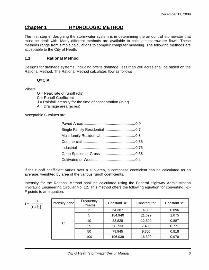
Chapter 1 HYDROLOGIC METHOD The first step in designing the stormwater system is in determining the amount of stormwater that must be dealt with. Many different methods are available to calculate stormwater flows. These methods range from simple calculations to complex computer modeling. The following methods are acceptable to the City of Heath. 1.1 Rational Method Designs for drainage systems, including offsite drainage, less than 200 acres shall be based on the Rational Method. The Rational Method calculates flow as follows Q=CiA Where Q = Peak rate of runoff (cfs) C = Runoff Coefficient
i = Rainfall intensity for the time of concentration (in/hr). A = Drainage area (acres) Acceptable C values are: Paved Areas ................................................. 0.9
Single Family Residential ............................. 0.7
Multi-family Residential ................................. 0.8
Commercial................................................... 0.85
Industrial ....................................................... 0.75
Open Spaces or Grass ................................. 0.35
Cultivated or Woods ..................................... 0.4
If the runoff coefficient varies over a sub area, a composite coefficient can be calculated as an average, weighted by area of the various runoff coefficients. Intensity for the Rational Method shall be calculated using the Federal Highway Administration Hydraulic Engineering Circular No. 12. This method offers the following equation for converting I-D-F points to an equation:
cbt
ai
Intensity ZoneFrequency
(Years)Constant "a" Constant "b" Constant "c"
2 64.387 14.300 0.896
5 184.940 21.699 1.075
10 83.828 12.500 0.887
25 58.733 7.400 0.771
50 79.945 9.300 0.818
100 196.039 16.300 0.978
C

December 11, 2009
City of Heath Stormwater Design Manual 4
1.2 Technical Release No. 55 For drainage areas, including offsite drainage, over 200 acres, the methods of SCS TR-55 shall be used to determine the peak rate of runoff. For the purposes of SCS TR-55 the following information shall be used where site-specific information is not available. Rainfall shall be based on Type II storm Soils shall be Group C Minimum Time of Concentration shall be 10 minutes Acceptable CN values shall be Paved Areas ................................................. 98
Single Family Residential ............................. 77-90 (submit supporting calcs.)
Multi-family Residential ................................. 80-90 (submit supporting calcs.)
Commercial................................................... 94
Industrial ....................................................... 91
Open Spaces or Grass ................................. 79
Cultivated or Woods ..................................... 77
Weighted CN values based on the area in each classification shall be calculated and used. 1.3 Alternate Hydrologic Methods Alternate hydrologic methods, such as SWMM programs, may be used to determine peak flows with the approval of the City Engineer. The design engineer shall submit all documentation necessary for the review and approval of alternate methods.

December 11, 2009
City of Heath Stormwater Design Manual 5
Chapter 2 RAINFALL 2.1 Design Storms Stormwater management facilities will be designed based on a SCS Type II storm with a duration of 24 hours and the following return periods: Streets and Gutters .................................................. 5 year storm Storm Sewers Just full capacity ........................................... 2 year storm Hydraulic grade line ...................................... 5 year storm Culverts Driveway ....................................................... 10 year storm Major Channel .............................................. 25 year storm Flood Hazard Area ....................................... 100 year storm Open Channels Road Side Ditches ........................................ 10 year storm Outside Flood Hazard Area .......................... 25 year flowing full
Flood Routing Path ....................................... 100 year flowing full Flood Hazard Area ....................................... 100 year flowing full The 24-hour storms for various frequencies, as defined by SCS TR-55, shall be as follows 1 year ............. 2.3 inches
2 year ............. 2.7 inches
5 year ............. 3.2 inches
10 year ........... 3.8 inches
25 year ........... 4.6 inches
50 year ........... 5.4 inches
100 year ......... 6.1 inches
Flood Hazard Areas, Flood Boundaries and Floodways shall be determined based on the latest Federal Emergency Management Agency (FEMA) Map for the City of Heath.

December 11, 2009
City of Heath Stormwater Design Manual 6
THIS PAGE LEFT INTENTIONALLY BLANK

December 11, 2009
City of Heath Stormwater Design Manual 7
Chapter 3 TIME OF CONCENTRATION The time of concentration is the estimated time required for runoff to flow from the most remote part of the drainage area under consideration to the point under consideration. It consists of the total time for overland sheet flow, shallow concentrated flow, and open channel flow. 3.1 Overland Flow Overland or sheet flow occurs as water begins to accumulate and flow toward the drainage system over the plane surface of the ground. Overland flow is limited to a distance of 100 feet (for more information see regarding this limit see: USDA-SCS, Time of Concentration, Northeast Hydrology Technical Note No.4, August 1986). The time of concentration for overland flow can be calculated from the Manning-kinematic solution as found in SCS TR-55 as follows
4.05.0
2
8.0k
cSP
Ln007.0T
Where Tc = Time of Concentration (hr)
nk = Manning’s roughness coefficient for overland flow L = Flow length (ft) P2 = 2-year, 24 hour rainfall (in) = 3.81 inches for Heath, OH S = slope (ft/ft)
Note that the Manning roughness coefficient for overland flow is not the same as the Manning’s coefficient for open channel flow. For the purpose of calculating overland flow, the following Manning’s roughness coefficient should be used. Surface nk
Smooth surfaces (paved or bare soil) ........... 0.011
Fallow ........................................................... 0.05
Cultivated Soils (<20% residue) ................... 0.06
(>20% residue) .................... 0.17
Grass ............................................................ 0.15-0.41
Range (natural) ............................................. 0.13
Woods (light underbrush) ............................. 0.40
(dense underbrush) ............................. 0.80
3.2 Shallow Concentrated Flow After 100 feet, stormwater accumulates and becomes shallow concentrated flow. Time of Concentration for slopes less than 0.005 ft/ft, the velocity can be calculated using the following formulas: V =16.1345 S 0.5 (Unpaved Areas) V =20.3282 S 0.5 (Paved Areas) Where V = average velocity (ft/s)

December 11, 2009
City of Heath Stormwater Design Manual 8
S = watercourse slope (ft/ft) Once the velocity is known, the time of concentration is calculated as
V60
LTc
Where Tc = Time of Concentration (min) L = Reach Length (ft) V = Velocity (ft/s) 3.3 Open Channel Flow Water that accumulates in channels, swales, gutters and storm sewers becomes open channel flow. The time of concentration for this flow can be determined by using the Manning’s Equation to determine the velocity as follows
SRn
486.1V 3
2
Where V = average velocity (ft/s) N = Manning’s roughness coefficient R = hydraulic radius (ft) S = channel slope (ft/ft) Once the velocity is known, the time of concentration is calculated as
V60
LTc
Where Tc = Time of Concentration (min) L = Reach Length (ft) V = Velocity (ft/s) 3.4 Offsite Drainage Off-site areas that currently drain to the site will be provided with a suitable drainage outlet and provisions shall be made to extend the stormwater system to adjacent properties. Offsite drainage from undeveloped land may, under existing conditions, have a high time of concentration due to overland and shallow concentrated flows. As this property develops, flow will become channelized through swales and storm sewers and the time of concentration will decrease. For this reason, the time of concentration for offsite drainage shall be estimated using a velocity of 3 feet/second as follows:
180
L10Tc
Where Tc = Time of Concentration (min)
L = Reach Length from the farthest point of the offsite drainage to onsite storm system (ft)

December 11, 2009
City of Heath Stormwater Design Manual 9
The minimum time of concentration shall be 10 minutes. No storage volume for off-site flow is required. Instead these flows will be routed through the stormwater system at the predevelopment rate for all storms using the above time of concentration. The developer may provide storage volume if necessary to reduce flows from the on-site and off-site areas to meet capacity restrictions downstream. Stormwater for property in the City of Heath that discharges into the system of another jurisdiction shall be designed to meet the requirements of the City of Heath or the other jurisdiction, whichever is more stringent. 3.5 Minimum Time of Concentration The minimum time of concentration shall be 10 minutes. 3.6 Alternate Calculations There may be cases where site conditions warrant more detailed evaluations of the time of concentration. This may occur due to an upstream drainage system or the presence of streams, wetlands or other hydraulic conditions. In these cases the engineer shall submit to the City Engineer time of concentration calculations and any background documentation for review and approval.

December 11, 2009
City of Heath Stormwater Design Manual 10
THIS PAGE LEFT INTENTIONALLY BLANK

December 11, 2009
City of Heath Stormwater Design Manual 11
Chapter 4 STREETS AND INLETS The street system provides a path for the stormwater to reach the stormwater system. Pavement, gutters and inlets must be designed with the movement of stormwater in mind. In order to provide for the movement of stormwater and to minimize flooding, streets shall be designed in accordance with the following standards. 4.1 Street design For street and inlet design the design storm is the 5-year rainfall. After initially designing the streets and inlets for the design storm, a check shall be made to ensure that the 10 and 100-year rainfalls do not exceed the maximum depth of flow. 4.2 Final Design All streets shall be provided with standard curb and gutter except as specified in the Subdivision Regulations and City of Heath CMS. The minimum gutter slope shall be 1.0% and the Manning’s “n” value shall be 0.015. Curb underdrains shall be provided. All underdrains shall be connected to the stormwater system. Areas without curb and gutter shall have adequate drainage systems to remove stormwater and prevent roadway flooding. Side ditch swales shall be designed to meet the standards of open channels and shall have a minimum bottom slope of 1.0%. Underdrains shall be provided at the pavement shoulder. These underdrains shall be connected to the stormwater system or daylighted to the side ditch if adequate depth is available. On privately maintained roads, “v” shaped pavement with a center storm drainage system may be used. Underdrains connected to the stormwater system will be provided along the centerline where street grades are less than 1.5%. Catch basin spacing shall comply with the requirements for inlet location and spacing. Catch basins in this addition shall have finger drains. Cul-de-sacs, eyebrows, and other special pavement sections shall be designed to provide adequate drainage. Pavement slopes shall be increased to provide a minimum gutter slope of 0.5% in the longer gutter section. Islands shall be designed to slope to the outside gutter. 4.3 Inlet Location and Spacing Curb Inlets shall be provided upstream of radius turns, at all pavement sag points, at the low points of street intersections and at points of maximum pavement encroachment. Runoff will not be allowed to enter the intersection. The maximum curb inlet spacing shall be 350 feet. A double inlet shall be used in sag points. Consideration must be given to the location of proposed curb ramps. Curb inlets shall be located upstream from the curb ramp. Curb inlets shall be located on the property line whenever possible to avoid conflicts with driveways and other utilities. 4.4 Flood Routing Streets shall provide the primary flood routing path for storms that exceed the design storm of the drainage system. Streets shall be graded to provide a flood routing path capable of conveying the

December 11, 2009
City of Heath Stormwater Design Manual 12
residual of the 100 year storm to a suitable outlet, or if runoff control is required, to the control facility. The major storm runoff is to be routed through the drainage system to determine if the combined capacity of the routing path and storm sewer is sufficient to maintain surface flows within permissible limits. The capacity of the conduit at any given point is assumed to be the same for the major storm as for the initial design storm for preliminary design purposes. If the major storm runoff exceeds the combined capacity of the street and storm sewer drainage system, revision in the major drainage design is required. Depth of flow shall not exceed the top of curb for the 5-year design storm. In addition, the 100-year water surface elevations shall not exceed 10-inch depth above the curb for local and collector streets and shall not exceed 6-inch depth at crown for arterial streets. In order for the depth of flow not to exceed the specified limits, especially for the 100-year rainfall, an open channel to storm sewer system may be required to convey some of the flow to a major channel. In determining the required capacity of surface channels and the storm sewer system, the street storm inlets and conduit provided shall be assumed to be carrying not more than one-half their design capacity. Routing of the major storm at culvert locations shall be at low areas of sags of vertical curves of streets. Elevations for the design of the street shall be such to permit the major storm to flow across the street and to prevent damage to any existing or proposed building structure. Routing shall be continuous from one development to the next. Where a major drainage way is located outside a street right-of-way, easements shall be provided and a grading plan shall be submitted with detailed engineering plan submission. The grading plan shall include elevations along the routing path and other elevations necessary to show that the major storm is contained within the planned area. 4.5 Spread Calculations The following are maximum spread of the 5-year rainfall design storm onto the pavement: For two-lane streets, maximum spread is 6 feet from the face of the curb. For four-lane streets, maximum spread is 8 feet from the face of the curb. The more restrictive condition for either maximum street spread or depth of flow shall control. When requested by the City Engineer, spread calculations shall be submitted. 4.6 Inlet Specifications Inlets shall be designed to meet the standards of the City of Heath and/or the Ohio Department of Transportation. Precast concrete modular units shall be in accordance with the applicable standard construction drawing or as approved by the City Engineer. Precast bases shall be placed on a foundation as noted on the standard drawings and CMS, a minimum of 3-inches of compacted sand, or as approved by the City Engineer. The compacted foundation shall be leveled to provide a uniform support for the entire area of the base.

December 11, 2009
City of Heath Stormwater Design Manual 13
All joints between modules shall be in conformance with ASTM C443, 706.10 or 706.11. Pipe entrances to the precast modular sections shall be in accordance with 706.15 or neatly grouted in place. All lift holes and other openings in the structure shall be thoroughly and neatly grouted with cement mortar or other suitable material approved by the City Engineer, after all pipes are placed into the structures. Frames, grates and castings shall be in accordance with the applicable standard construction drawing and CMS or as approved by the City Engineer and shall be set in a mortar bed at the locations and elevations specified. Curb inlet castings which have grate bars parallel to traffic flow will not be accepted. All openings within pavement areas shall be bicycle safe. All castings shall be stamped “Drains to River”.

December 11, 2009
City of Heath Stormwater Design Manual 14
THIS PAGE LEFT INTENTIONALLY BLANK

December 11, 2009
City of Heath Stormwater Design Manual 15
Chapter 5 STORM SEWERS While streets provide the initial collection of stormwater, storm sewers convey the stormwater to the outlet. Storm sewers shall be designed to adequately convey the design storm within the pipe system and minimize the surface ponding of water at inlets. Storm sewer sizing shall be based on the just full capacity for a 2-year frequency rainfall. After initial sizing, a hydraulic grade line (HGL) check shall be made for a 5-year frequency rainfall. If the check shows water flowing out of the system, then the system needs to be revised to contain the rainfall. 5.1 Design Criteria Storm sewers shall be designed to receive stormwater from the entire tributary area. The minimum cover for storm sewers crossing streets with curb and gutter shall be 24-inches from the subgrade, but shall be concrete encased where the cover is less than thirty inches. Storm sewers outside the pavement but inside the right-of-way shall have 24-inches of cover. All other storm sewers shall have a minimum of two feet of cover. If this cover cannot be maintained, concrete encasement will be required. Trench backfill shall be as per the requirements of the City of Heath.
The minimum storm sewer size is 12-inches for all mainline storm sewers and 12-inches for storm laterals. All new storm sewers shall be constructed of concrete pipe or HDPE pipe meeting the requirements of ODOT 706.02 or 707.33 respectively. Alternate materials may be approved by the City Engineer under special design conditions. Storm sewers shall be sized using the Manning’s equation:
SRn
486.1V 3
2
Where V = average velocity (ft/s) n = Manning’s roughness coefficient=0.013 R = hydraulic radius (ft) S = channel slope (ft/ft) The following numbers should be used for the manning “n” value. Concrete pipe ............................................... 0.013
HDPE smooth lined Pipe ............................ 0.012
The storm sewer shall be designed to insure self-cleaning. The minimum velocity shall be 3 fps. The maximum velocity shall be 15 fps. The size of the sewer must be adequate for flowing full, based on the design storm. The main pipe, if over 24-inches, in a sewer system will be required to be separated from all inlets unless a special design is submitted for approval. The flow line of pipes should be set such that the crown of the pipes, at junctions, are at the same elevation; if the outlet elevation permits, the crown of the outlet pipe may be lower. The flow line elevations of sewers should be set to avoid using concrete encasement.

December 11, 2009
City of Heath Stormwater Design Manual 16
A minimum separation of 18-inches shall be maintained between the storm sewer and all water and sanitary sewer lines. A 12-inch separation shall be maintained between the storm sewer and all other buried utilities. It is the responsibility of the designer to locate all buried utilities to the best of their ability. 5.2 Manholes and Catch Basins Manholes and catch basins shall be designed to meet the standards of the City of Heath and/or the Ohio Department of Transportation. All structures must be sealed inside and out. Precast concrete modular units shall be in accordance with the applicable standard drawing or as approved by the City Engineer. Precast bases shall be placed on a foundation as noted on the standard drawings, a minimum of 3-inches of compacted sand, or as approved by the City Engineer. The compacted foundation shall be leveled to provide a uniform support for the entire area of the base. All joints between modules shall be in conformance with ASTM C443, 706.10 or 706.11 per the CMS. Pipe entrances to the precast modular sections shall be in accordance with 706.15 or neatly grouted in place per the CMS. All lift holes and other openings in the structure shall be thoroughly and neatly grouted with cement mortar or other suitable material approved by the City Engineer, after all pipes are placed into the structures. Frames, grates and castings shall be in accordance with the applicable standard drawing or as approved by the City Engineer and shall be set in a mortar bed at the locations and elevations specified per the CMS. Manholes shall be located at points in the storm sewer where the following occur:
1. Junctions of Pipes
2. Change in Direction
3. Change in Slope
4. Change in Pipe Size
5. Change in Pipe Material
6. End of Pipe Run
7. Maximum Spacing of 350 feet
Where drainage is needed, the manhole will be equipped with a grate top or a catch basin will be substituted. Catch basins and manholes located in paved areas where there are no curb underdrains shall be provided with a minimum of 10 feet each direction of underdrain upstream of the storm sewer to remove subsurface drainage. All Catch basins shall be as per ODOT Standard Drawings and installed as per item 604 of the ODOT Construction and Materials Specifications.
December 11, 2009
City of Heath Stormwater Design Manual 17
Catch basins will be located outside of the pavement at points where drainage is collected. Catch basins located in paved areas or in the right-of-way will be equipped with a heavy-duty grate and frame suitable for the application. 5.3 Yard Drains Yard drains meeting the standards of the City of Heath may be used at locations approved by the City Engineer. 5.4 Roof Drains All new curb and gutter construction will include the provision for a drain outlet for each property through the curb to the gutter. Where roof pipe leaders are present in replacement sections of curbing, provisions shall be made in the new curbing to accommodate those leaders. Roof drains may discharge to drainage swales where sufficient depth is available. New roof drain connections to the gutter shall be core drilled. Roof drains, foundation drains and other clean water connections to the sanitary sewer system are prohibited in the City of Heath. 5.5 Field Tiles Field tiles encountered during construction shall be connected to the stormwater management system. 5.6 Headwalls Storm sewers that discharge to surface waters shall be provided with a suitable concrete full height headwall meeting the requirements of The City of Heath and ODOT Standard Drawings. The invert of the storm sewer shall be set no lower than 6-inches above the bottom of the channel. In flood hazard areas, the invert at the headwall shall be set no lower than 6-inches above the 100 year water level. Channel erosion control shall be provided at the outlet of all storm sewers. Rock channel protection shall meet the requirements of ODOT 601; size and length of protection shall be in accordance with The ODOT Location & Design Manual Volume 2 – Drainage Design. 5.7 Easements Storm sewers outside the public right-of-way shall be provided with an easement for maintenance and repair. A specifically located and described, 20-foot minimum width access easement shall be required from the maintenance easement to the nearest public right-of-way. Maintenance and access easements are to be kept free of obstructions. Additional easements may be required for storm sewers that are located in the public right-of-way if necessary to provide room for maintenance and repair activities.

December 11, 2009
City of Heath Stormwater Design Manual 18
THIS PAGE LEFT INTENTIONALLY BLANK

December 11, 2009
City of Heath Stormwater Design Manual 19
Chapter 6 CULVERTS All prefabricated structures including concrete pipe, prefabricated box culverts, etc., shall be considered culverts. Culverts under driveways shall be designed for the 10-year storm. All other culverts, except culverts that cross a major channel or are located in the floodplain of a major channel shall be designed for the 25-year storm. Culverts that cross a major channel or are located in the floodplain of a major channel shall be designed for the 100-year storm. Final design shall indicate headwater elevations for the design storm and 100-year rainfall for all culverts except culverts under driveways, crossing a major channel, or located in the floodplain of a major channel. 6.1 Design Criteria Single span culverts, including concrete box or slab top, should always be considered in lieu of multiple cell pipe culverts when they are the only structures that will meet the physical requirements introduced by rigid headwater controls. A culvert should be located along the flowline of the ditch or swale that it is draining. The plan for each culvert shall have the drainage area in acres and the estimated runoff or design discharge in cubic feet per second shown. The culvert inlet flow line elevation should be set such that it will be deep enough to provide an adequate outlet for future storm sewer improvements upstream. Culverts shall be sized utilizing orifice and weir flow equations where applicable for individual site conditions and storm frequencies. Inlet and outlet control nomographs for evaluation of culvert hydraulics may also be utilized to evaluate culvert hydraulics. Culverts shall be designed for the design storm with a maximum allowable headwater elevation of:
1. 18 inches below top of curb
2. 12 inches below edge of pavement
3. 1.5 times pipe diameter
4. 2’ below any existing or proposed building first floor elevation.
5. Diameter or rise plus 4 feet or 2D, whichever is lower, in deep ravines.
Culverts except for driveway culverts shall maintain a headwater of no more than 2D or the edge of pavement for the 100-year storm. There shall be no increase in the 100-year headwater in a FEMA designated floodway. The acceptable Manning’s “n” value shall be
Box Culvert ................................................... 0.011
Slab Top Culvert ........................................... 0.03 to 0.05
Reinforced Concrete Pipe ............................. 0.013

December 11, 2009
City of Heath Stormwater Design Manual 20
Entrance Loss Coefficient acceptable for design shall be
Box Culvert and Slab .................................... 0.2 to 0.5
Concrete Pipe ............................................... 0.2
The minimum cover desired is 30 inches to pavement subgrade. The maximum cover shall be determined based on the supporting strength of the conduit. The structural design criteria for culverts will be the same as that required by the Ohio Department of Transportation. 6.2 Pipe Standards All culverts shall be constructed of concrete pipe meeting the requirements of ODOT 706.02, 706.03, 706.04, or 706.05. The City Engineer, under special design conditions, may approve alternate materials. 6.3 Drainage Structures Open culverts will not generally contain manholes, surface inlets or catch basins. Special design considerations such as site topography or maintenance considerations may require that drainage or access structures be included in the design, with the approval of the City Engineer. These structures shall meet the same requirements as structures used in the storm system. 6.4 Headwalls and End Treatments Headwalls or other approved end treatments will be required for all culverts. At a minimum, a full height headwall, with or without wings, will be installed. Half height headwalls may be approved on a case-by-case basis. All headwalls must be sealed with an approved sealer. Energy dissipators and erosion protection shall be required when the velocity of the flow from the culvert exceeds the allowable velocity. The maximum allowable outlet velocity is
Bare Earth Channel ...................................... 6 fps
Rock Protection ............................................ 18 fps
Stilling Basin ................................................. Over 18 fps
6.5 Channel Protections and Erosion Control Channel erosion control shall be provided at the outlet of all culverts and at the inlet wingwalls of full height headwalls. Rock channel protection shall meet the requirements of ODOT 601; size and length of protection shall be in accordance with The ODOT Location & Design Manual Volume 2 – Drainage Design.

December 11, 2009
City of Heath Stormwater Design Manual 21
Chapter 7 OPEN CHANNELS Open channels may be naturally occurring small streams or man made ditches and swales. Their purpose is to carry large amounts of water away from property to the final discharge at the stream, river or lake. Open channels shall be designed to insure the passage of major storms without damage to local property. 7.1 Enclosure of Open Channels In general, open channels are not permitted by the City of Heath. If site conditions are such that open channels would be beneficial, the City Engineer must be notified. In no case will open channels be allowed without prior permission from the City Engineer. It must also be noted that the requirements of OEPA and the US Army Corps of Engineers must be complied with on all open channel issues. Roadside ditches shall be designed for the 10-year storm. All other open channels, except major channels as defined herein, shall be designed for the 25-year storm. Major channels shall be designed for the 100-year storm. Final design shall indicate water surface elevations for the design storm. In addition, the 100-year flood profile and 100-year flood area shall be shown for all open channels. The recommended minimum channel bottom slope shall be 0.50 percent for paved or lined channels and 1.00 percent for grass or sod lined channels. 7.2 Design Criteria Open channel flow may be evaluated utilizing Manning’s equation.
SRn
486.1V 3
2
Where V = average velocity (ft/s) n = Manning’s roughness coefficient=0.013 R = hydraulic radius (ft) S = channel slope (ft/ft) Acceptable Manning’s “n” shall be:
Sod or Jute Mat Lining .................................. 0.05
Paved Lining ................................................. 0.015
Rock Protection ............................................ 0.08
Existing Lining............................................... 0.025 to 0.20
Site-specific conditions, such as culverts, floodplains, or stormwater management systems, may require more detailed evaluation.
Storm drainage ditches and channels shall be designed to protect against erosion under high water conditions. The allowable design storm velocities for all new ditches shall be as follows:

December 11, 2009
City of Heath Stormwater Design Manual 22
3.0 fps with seeding 5.0 fps with sod or jute mat lining Over 5 fps requires special lining
The allowable velocities in existing channels shall be determined by the ability of the channel to handle the flow satisfactorily.
The side slope of stormwater drainage ditches and channels shall be designed to insure maintenance. The maximum side slopes shall be:
Seeded Soil ........................... 3:1
Concrete Paved .................... 2:1
Rock ...................................... 2:1
7.3 Easements Access to storm drainage ditches and channels shall be by means of maintenance easements. Such maintenance easements shall be not less than the width of the ditch at the top of the bank plus twenty feet each side, measured horizontally, from the top of banks. A specifically located and described, 20-feet minimum width access easement shall be required from the maintenance easement to the nearest public right-of-way. Maintenance and access easements are to be kept free of obstructions. Surface water collector swales within rear yard and side yard areas of residential subdivisions and on all non-residential parcels draining more that 5 acres shall be constructed within a drainage easement possessing a minimum width of twenty feet. For residential properties the drainage swale should be generally constructed approximately in the middle of the easement. Maintenance responsibilities will be determined and so stated in the easement or on the Final Plat. In general, the City will not be responsible for these facilities.

December 11, 2009
City of Heath Stormwater Design Manual 23
Chapter 8 DETENTION OR RETENTION & WATER QUALITY In developed and developing urban and suburban areas, several means for controlling stormwater runoff can be used. The following types of storage facilities may be considered for detention: rooftops, parking lots, underground tanks and surface basins or ponds. 8.1 Parking Lot Storage Parking lot storage is surface storage where shallow ponding is designed for specific graded areas of the parking lot. Controlled release features are incorporated in the surface drainage system of the parking lot. Parking lot storage is a convenient multi-use structural control method where impervious parking lots are planned. Design features include small ponding areas with controlled release by orifice plates or pipe-size and slope, and increased curb heights. Ponding areas in parking or traffic areas shall be designed for a maximum potential depth of nine (9) inches. Flood routing or overflow must occur after the maximum depth is reached. The major disadvantage is the inconvenience to users during the ponding function. This inconvenience can be minimized with proper design consideration. Clogging of the flow control device and icy conditions during cold weather are maintenance problems. Parking lot design and construction grades are critical factors. This method is intended to control the runoff directly from the parking area, and is usually not appropriate for storing large runoff volumes. 8.2 Tank Storage Tank storage is an underground tank or chamber, either prefabricated or constructed in place, which has a special controlled release feature. This method is most applicable where land area is very valuable, such as in industrial and commercial areas. Construction costs and operating costs, which may include pumps, makes this method relatively expensive. Storage trenches, a variation on the basic tank storage, are rock-filled underground storage tanks. The storage is provided within the void between the rock material. 8.3 Surface Basins or Ponds, Wet Ponds, or Retention Basins Wet ponds are permanent ponds where additional storage capacity is provided above the normal water level and special features for controlled release are included. Historically, wet ponds have proven extremely effective in abating increased runoff and channel erosion from urbanized areas. They are a major Soil Conservation land treatment practice. Some problems often encountered with wet ponds are: site reservation (land requirements), permanent easements, complexity of design and construction and maintenance problems. Because of large land requirements, and the necessity of maintaining a permanent pool of water, wet ponds have a broader application for in-stream control where large watershed areas are involved compared to their use as on site facilities for small urban areas. However, the recreational and aesthetic benefits of permanent wet ponds may justify certain on-site applications. If this option is selected, it will be the responsibility of the Developer to construct and maintain the system with public safety measures in place. Due to siltation, maintenance, and safety problems created by such basins, no wet basins shall be permitted for the purposes of retention of storm water, in a single family or multi-family development.

December 11, 2009
City of Heath Stormwater Design Manual 24
Wet basins will be considered in the development of Industrial and Commercial developments but may not be closer than 500’ to any residential areas and be fenced. Side slopes for a Retention Facility shall be 4:1 Maximum – below permanent storage and 6:1 Maximum – above permanent storage. Rock Channel Protection, Type D, must be placed at the normal water elevation, around the entire perimeter of the basin, five feet wide, centered on the normal water elevation. 8.4 Dry Basins or Detention Basin Dry basins are surface storage created by constructing a typical excavated or embankment basin. There is no normal pool level and a specific controlled release feature is included to control the rate of discharge. Dry basins are the most widely used method of stormwater management. The soil permeability and water storage potential are not as important with dry basins as with wet basins. Therefore, dry basins have the greatest potential for broad applications. They can be utilized in small developments because they can be designed and constructed as small structures. Dry basins are often less costly than wet ponds because they do not require extensive design and construction considerations. They can be designed for multi-use purposes such as recreation and parks. Detention basin invert ditches with slopes less than 1% shall be provided, from the inlet to the outlet of all structures, and shall be paved. Such ditches shall be in accordance with the paved gutters as detailed in the ODOT Standard Drawing. Detention basin bottoms shall be sloped to drain, such slopes shall be sufficient to mitigate against “flat spots” developing due to construction errors and soil conditions; or, such bottoms shall be paved. The absolute minimum transverse slope for the bottoms of such facilities shall be 1% and 2.0% is the recommended transverse slope. Debris-Control and/or animal guard structures may be required in some detention situations and should be considered as an essential part of design. The procedure recommended for use is Hydraulic Engineering Circular No. 9, available from the Superintendent of Documents, U.S. Government Printing Office. Proof Surveys shall be performed by the Developer, Contractor, or other entity constructing the stormwater drainage facilities, in order to demonstrate conclusively that the facilities are constructed to the elevations, slopes, grades, and sizes shown on the reviewed plans on file with the City. Such surveys shall be conducted by a registered Professional Surveyor, shall employ standard survey techniques, and shall produce original field notes which shall be furnished to the City for review and record purposes. Reduction of notes, and any plotting necessary to make the notes interpretable, shall be by the surveyor performing the proof survey. Proof surveys shall be in addition to, and separate from, other construction surveys which may be conducted by the City or its agent. All discrepancies revealed in the as-constructed facilities by the proof survey shall be rectified by the Developer, Contractor, or other entity constructing the storm water drainage facilities, and the proof survey re-performed, in order to demonstrate conformance.

December 11, 2009
City of Heath Stormwater Design Manual 25
8.5 Access and Maintenance Easements Specific, dedicated easement rights shall be required, in order to provide necessary access to all stormwater facilities. Generally, a maintenance easement of 20 foot minimum width, in addition to the size of the stormwater facility when flooded, is required, from the easement at, alongside, or around the stormwater facility, to the nearest public right-of-way. The 20 foot minimum width outside the flooded facility must be on a slope no steeper than 10:1. The detention/retention facilities, unless otherwise agreed upon by the City of Heath, shall be owned and maintained by the owner of the development, homeowners association, or condominium owners association. The owner/developer is responsible to maintain the storm drainage system in such a way as to not reduce the capacity of the system. If the owner/developer does not maintain the drainage system, the approved plans will become void and the City will plug the system at the outlet. 8.6 Water Quality Requirements All stormwater facilities (detention, retention, storm sewer, etc.) shall meet the requirements of the current Ohio EPA NPDES permit for Water Quality. Maintenance of the Water Quality Facilities shall be the responsibility of the Owner/Developer or Home Owners/Condominium Association.

December 11, 2009
City of Heath Stormwater Design Manual 26
THIS PAGE LEFT INTENTIONALLY BLANK
December 11, 2009
City of Heath Stormwater Design Manual 27
Chapter 9 STORMWATER POLLUTION PREVENTION Construction activities required as part of land development necessitate the removal of natural ground cover, creating the potential for erosion to occur. Erosion, and the movement of the soil off the site and into the stormwater control system, can lead to water quality impacts. Excessive soil in the stormwater system can also cause the system to malfunction or require excessive maintenance to keep the system operational. Proper erosion control techniques can minimize the loss of soil on the site. 9.1 Policy The policy of the City of Heath is that no person shall cause or allow earth-disturbing on a development prior to submittal and approval of a Stormwater Pollution Prevention Plan (SWPPP). In addition, should the proposed project fall under the jurisdiction of the current Ohio EPA NPDES permit, the developer shall prepare and submit an OEPA Notification of Intent (NOI). A copy of the approved NOI shall be submitted to the City of Heath prior to commencement of construction activities. Approval of the SWPPP by the City of Heath does not constitute approval by the OEPA. 9.2 Design Criteria Permanent control provisions shall be coordinated with the temporary erosion control to the extent possible to assure economical, effective and continuous erosion control throughout the construction and post-construction period. Perimeter control and other sediment trapping measures shall be installed to stop the movement of sedimentation off the site. Such controls will include: stabilized construction entrances, straw bale dams and fabric fencing, temporary sediment traps, sediment basins and diversions. Storm drains, both on and off the site, shall be protected from sedimentation. Stormwater retention or detention facilities shall not be used as sedimentation traps without the approval of the City Engineer. If such facilities are used as a sedimentation trap or sedimentation basin, the facility shall be thoroughly cleaned of all sedimentation and returned to full design capacity prior to the release of the construction bond. Construction shall be scheduled to minimize the amount of area disturbed at any one time. Disturbed areas that are at finish grade shall be permanently seeded within seven days. Other areas of disturbed soil shall be rough graded to provide drainage and temporarily seeded if they are to remain dormant for more than 30 days. Slope protection shall be provided by use of temporary and permanent diversion dikes, vegetative cover and slope drains. Concentrated stormwater flows shall not be allowed to flow down cut or fill slopes without proper slope stabilization. Concentrated stormwater runoff leaving a development site shall be outletted to an open channel, storm sewer inlet or culvert which is capable of receiving the discharge. Runoff velocities shall be controlled to prevent erosion. Appropriate measures shall be taken to minimize or eliminate wastes and unused building materials and all pollutants from being carried from the site by runoff. Proper storage, handling and use of all potentially polluting substances shall be employed.

December 11, 2009
City of Heath Stormwater Design Manual 28
Public and private roadways shall be kept cleared of accumulated sediment. Provisions for proper dust control may be required as deemed necessary. Where construction crosses a stream or channel, a temporary stream crossing will be needed. Erosion Control design shall meet the requirements of the City of Heath Standard Drawings and Standard Notes. 9.3 Maintenance During Construction All disturbed areas that are exposed to precipitation, structural control measures and locations of vehicle entrance and exit shall be inspected at least once every seven days and within twenty-four hours of a storm event greater than 0.5 inches. Inspection shall be continued until all disturbed areas are stabilized; structural controls are removed or converted to stormwater management facilities. Corrective action will be taken for all noted deficiencies. Such actions shall be initiated within 24-hours of inspection notification. Sediment deposits shall be removed from straw bale and filter fence barriers upon reaching approximately one-half the height of the barrier at its lowest point or causes a silt fence to bulge and should be deposited at a controlled fill area. Sediment deposits shall be removed from diversion channels, dikes, outlet channels and stabilized areas after every rainfall. Any area damaged by erosion shall be repaired and reseeded within 24-hours or as soon as the soil dries sufficiently to allow work to proceed. Temporary stream crossings shall be inspected after every rainfall and at least weekly for assessment of damage due to stormwater flows or construction equipment. Necessary repairs shall be made within 24-hours or as soon as the soil dries sufficiently to allow work to proceed. The City maintains the right to inspect any site of land disturbance at any reasonable time and to require compliance with regulations and soil erosion control plan.

December 11, 2009
City of Heath Stormwater Design Manual 29
Chapter 10 DESIGN SUBMISSION 10.1 Plans Preliminary Plan and Construction Plan contents shall be as per the pertinent sections of the City of Heath Development Regulations. 10.2 Calculations Appropriate calculations to document and justify the engineering design of the project shall be submitted for review. The calculations shall be stamped by the Design Engineer. A partial list of calculations is given below. All of these calculations may not apply to every project.
Spread Calculations-Indicating the gutter capacity of streets and amount of pavement flooded (if requested)
Grate Calculations-Indicating the capacity of inlet grates to handle storms (if requested) Storm Sewer Design Calculations-Indicating drainage to and capacity of storm sewers
(required) Culvert Design Data Sheet Calculations-Indicating drainage to and capacity of culverts
(required) Channel Calculations-Indicating drainage to and capacity of all channels (required for
new or as requested) Storage Calculations-Indicating the amount of storage required and amount provided
(required) Orifice Calculations-Indicating sizing (required) Weir Calculations-Indicating sizing (required) Time of Concentration Calculations-Documenting existing and design time of
concentration (if requested) C and CN Calculations-Documenting existing and design C and CN values (if requested) Downstream Capacity Calculations-Verifying capacity of downstream systems (required) Other Calculations Construction Sedimentation Water Quality Calculations (OEPA NPDES) Post-Construction Water Quality (OEPA NPDES)
10.3 Cost The Developer will reimburse the City for all expenses related to the review of the submitted plan and inspection of construction.

December 11, 2009
City of Heath Stormwater Design Manual 30
THIS PAGE LEFT INTENTIONALLY BLANK