Embed Size (px)
Citation preview
STORMWATER MANAGEMENTSTORMWATER MANAGEMENT
ByByJohn Gribbin, P.E.John Gribbin, P.E.
Revised by Prof. Washington for CET413Revised by Prof. Washington for CET413
Topics
• Effects of Land Development• Stormwater Management Regulations
• Best Management Practices• Runoff by Rational Method
• Runoff by NRCS Method• Runoff Hydrographs• Reservoir Routing
• Detention Basin Design
Effects of Land Development
• Increase of Runoff Rate• Increase in Runoff Volume
• Decrease in Recharge• Increase in Pollutants• Increase in Erosion
• Potential for Flooding Downstream
Areas Impacted
• Streams• Lakes
• Wetlands• Private Property• Public Property
Best Management Practices*
Goals:• Control Runoff
Quantity• Control Runoff Quality• Control Groundwater
Recharge
Implementation:• Non-Structural
Strategies• Structural Strategies
* BMP can be found at
www.njstormwater.org
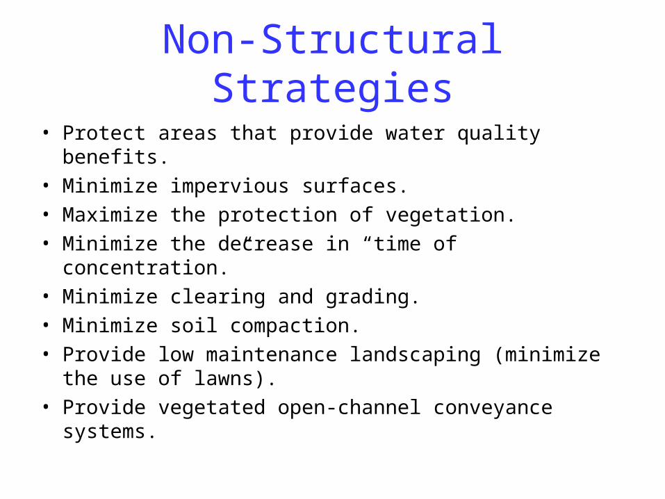
Non-Structural Strategies
• Protect areas that provide water quality benefits.• Minimize impervious surfaces.• Maximize the protection of vegetation.• Minimize the decrease in “time of concentration.”• Minimize clearing and grading.• Minimize soil compaction.• Provide low maintenance landscaping (minimize the use
of lawns).• Provide vegetated open-channel conveyance systems.
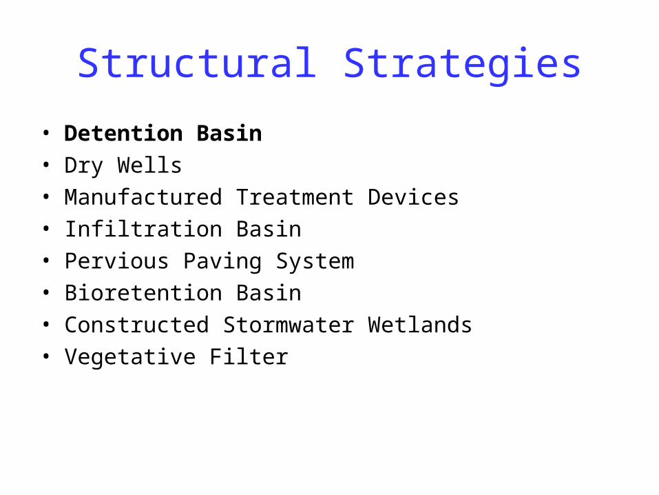
Structural Strategies
• Detention Basin• Dry Wells• Manufactured Treatment Devices• Infiltration Basin• Pervious Paving System• Bioretention Basin• Constructed Stormwater Wetlands• Vegetative Filter
Runoff Calculations
• Rational Method
• Modified Rational Method
• NRCS Method
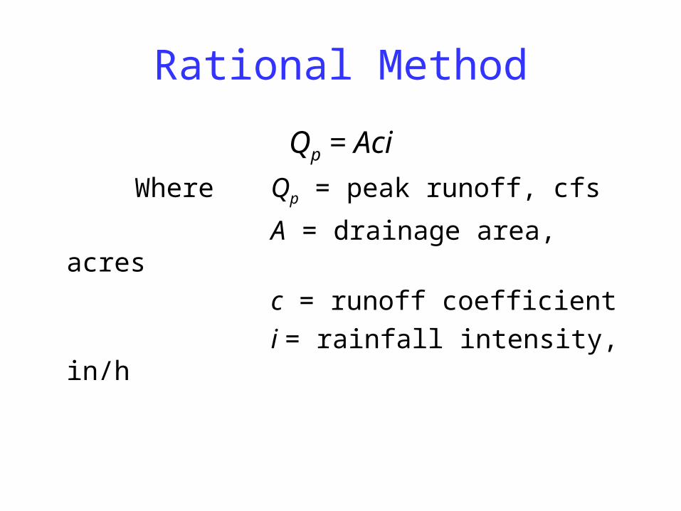
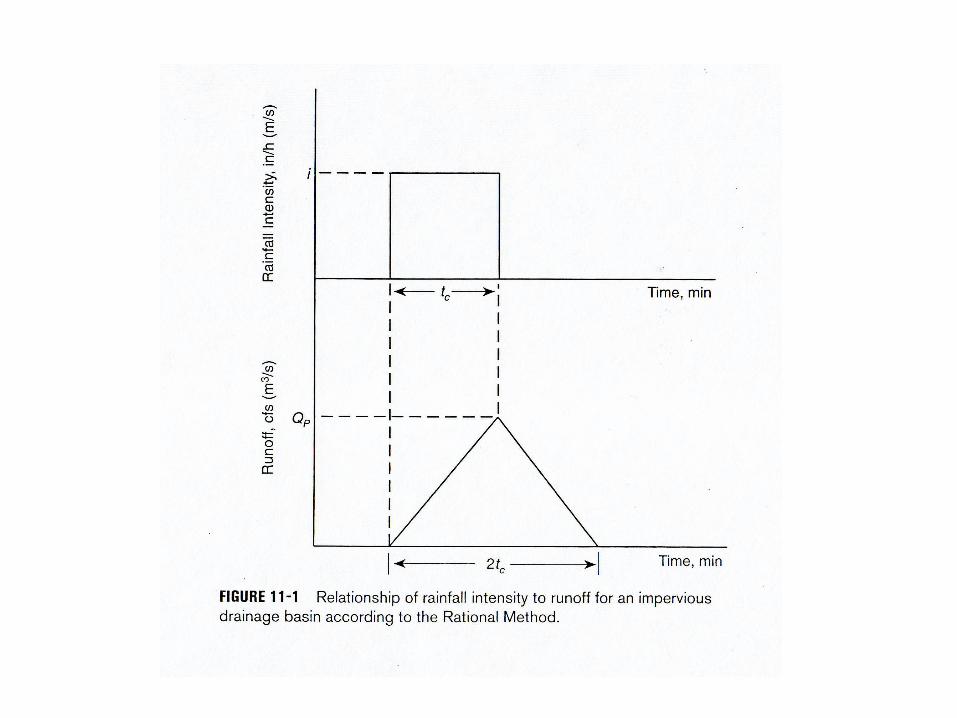
Rational Method
Qp = Aci
Where Qp = peak runoff, cfs
A = drainage area, acres
c = runoff coefficient
i = rainfall intensity, in/h
Rational Method
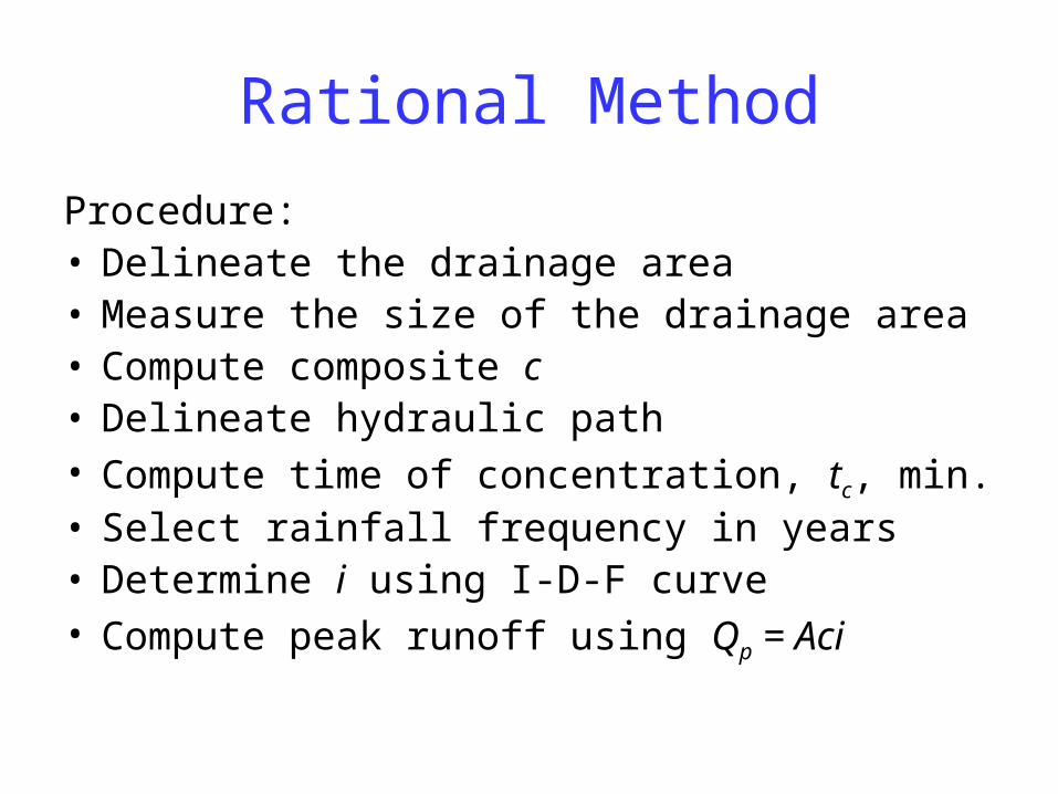
Procedure:• Delineate the drainage area• Measure the size of the drainage area• Compute composite c• Delineate hydraulic path• Compute time of concentration, tc, min.• Select rainfall frequency in years• Determine i using I-D-F curve• Compute peak runoff using Qp = Aci
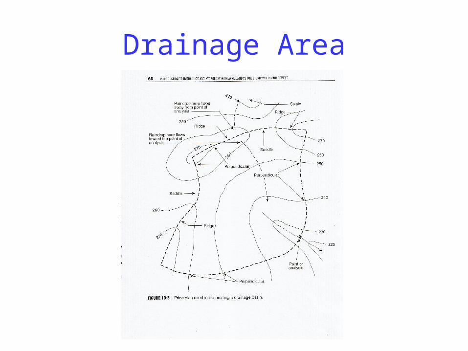
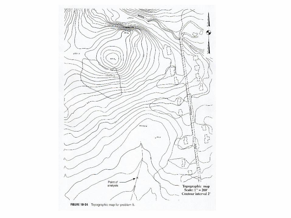
Drainage Area
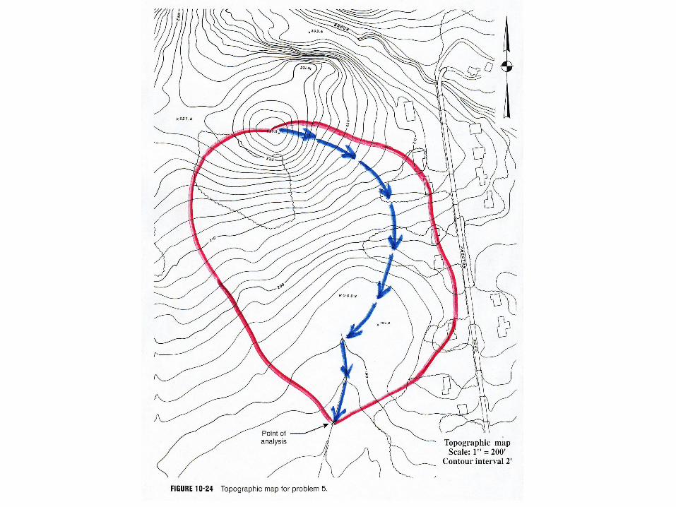
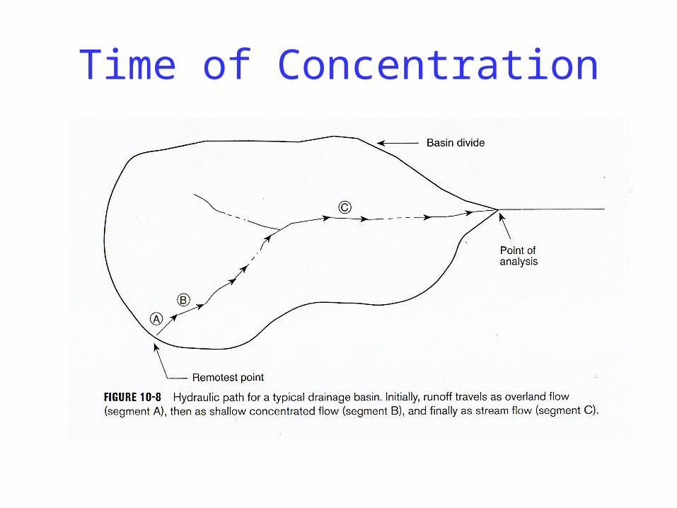
Time of Concentration
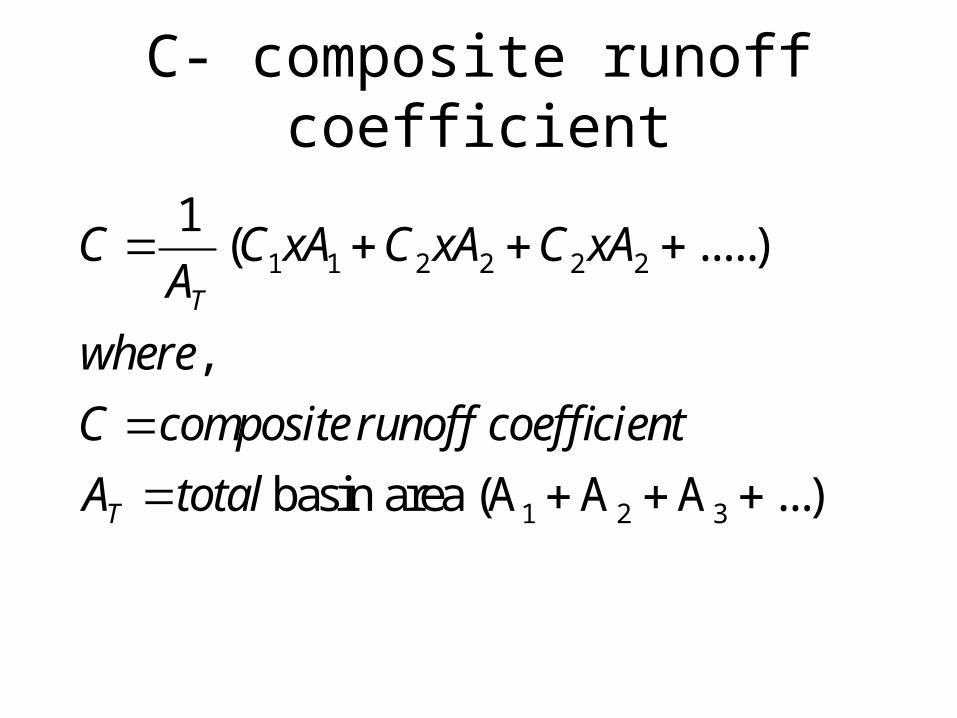
C- composite runoff coefficient
1 1 2 2 2 2
1 2 3
1( .....)
,
basin area (A A A ...)
T
T
C C xA C xA C xAA
where
C composite runoff coefficient
A total
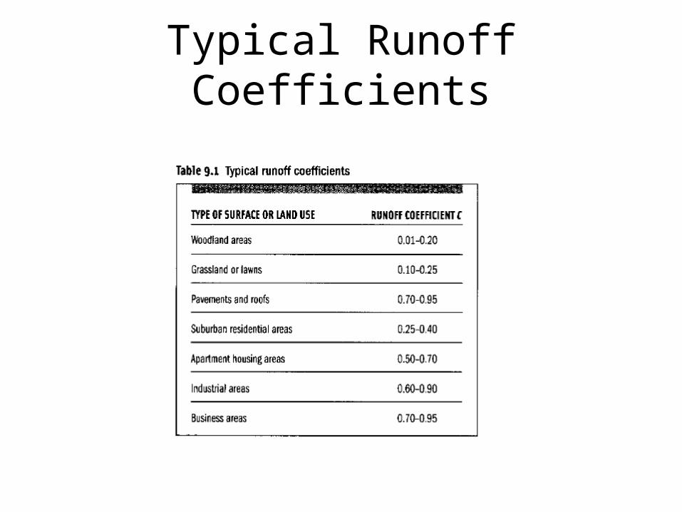
Typical Runoff Coefficients
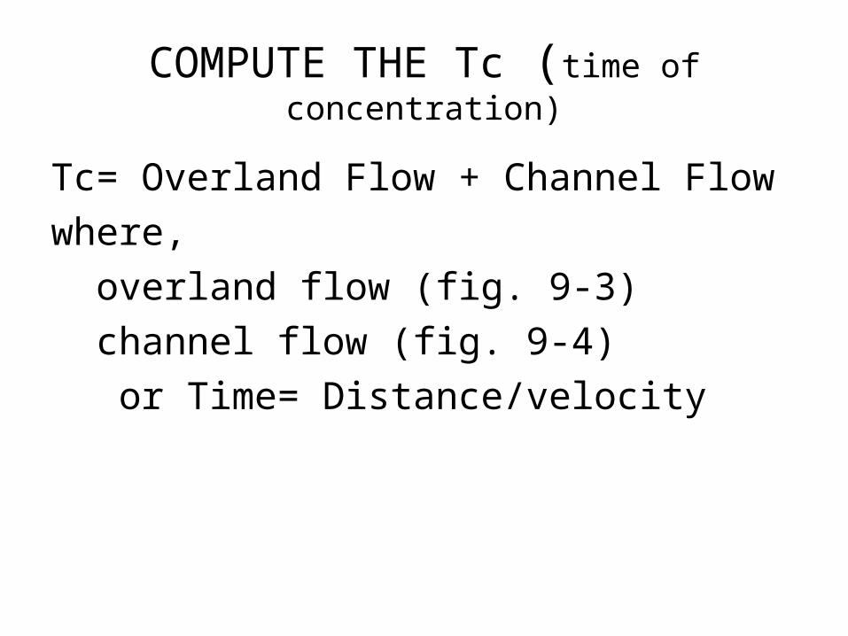
COMPUTE THE Tc (time of concentration)
Tc= Overland Flow + Channel Flow
where,
overland flow (fig. 9-3)
channel flow (fig. 9-4)
or Time= Distance/velocity
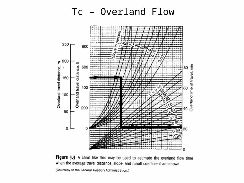
Tc – Overland Flow
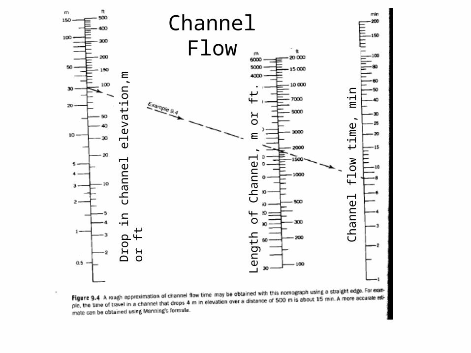
Channel Flow
Dro
p in
cha
nnel
ele
vatio
n,m
or
ft
Leng
th o
f C
hann
el,
m o
r ft
.
Cha
nnel
flo
w t
ime,
min
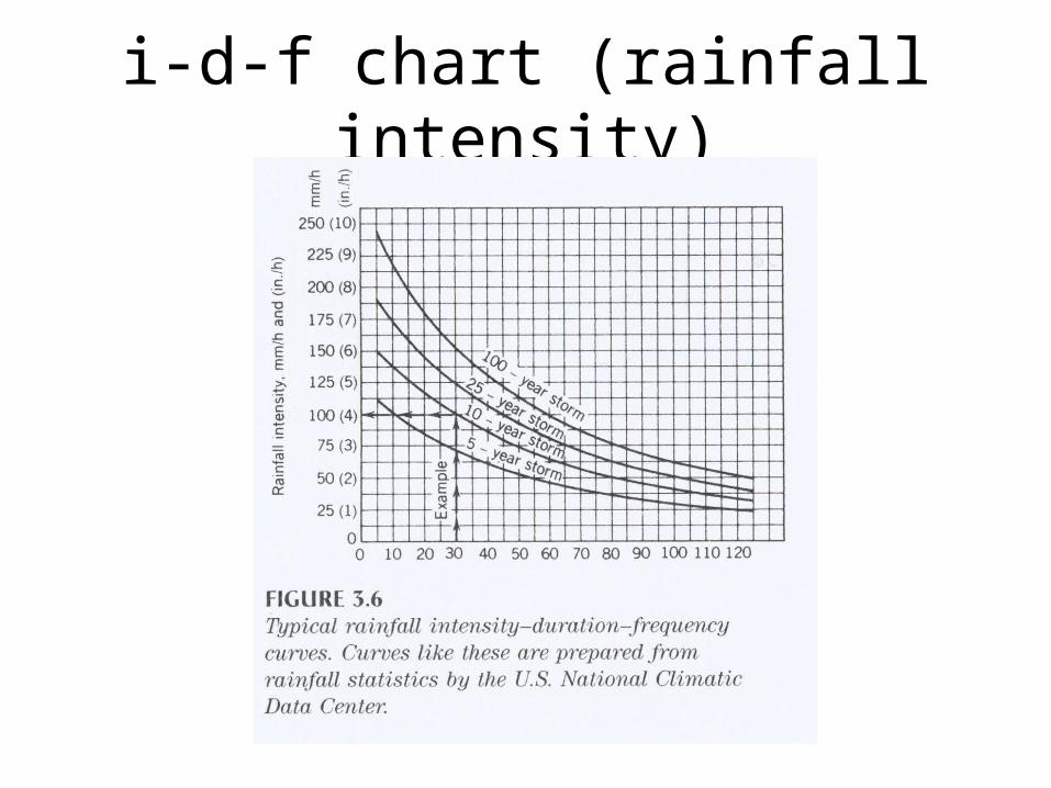
i-d-f chart (rainfall intensity)
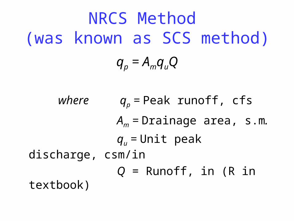
NRCS Method (was known as SCS method)
qp = AmquQ
where qp = Peak runoff, cfs
Am = Drainage area, s.m.
qu = Unit peak discharge, csm/in
Q = Runoff, in (R in textbook)
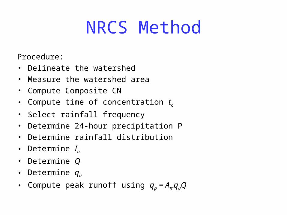
NRCS Method
Procedure:• Delineate the watershed• Measure the watershed area• Compute Composite CN
• Compute time of concentration tc
• Select rainfall frequency• Determine 24-hour precipitation P• Determine rainfall distribution
• Determine Ia
• Determine Q
• Determine qu
• Compute peak runoff using qp = AmquQ

CN-SCS runoff curve number
Land use description
Forests
Meadows
Grass - Lawns
Commercial-Business
Residential
Pavement- Roofs
Typical Runoff Coefficients
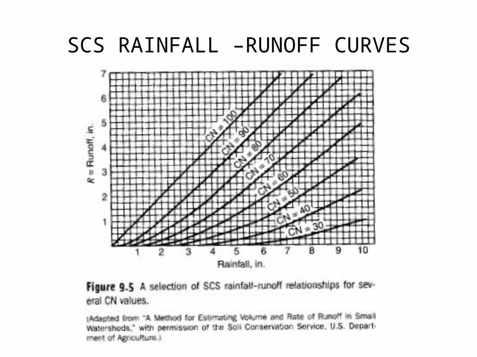
SCS RAINFALL –RUNOFF CURVES
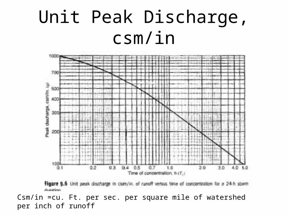
Unit Peak Discharge, csm/in
Csm/in =cu. Ft. per sec. per square mile of watershed per inch of runoff
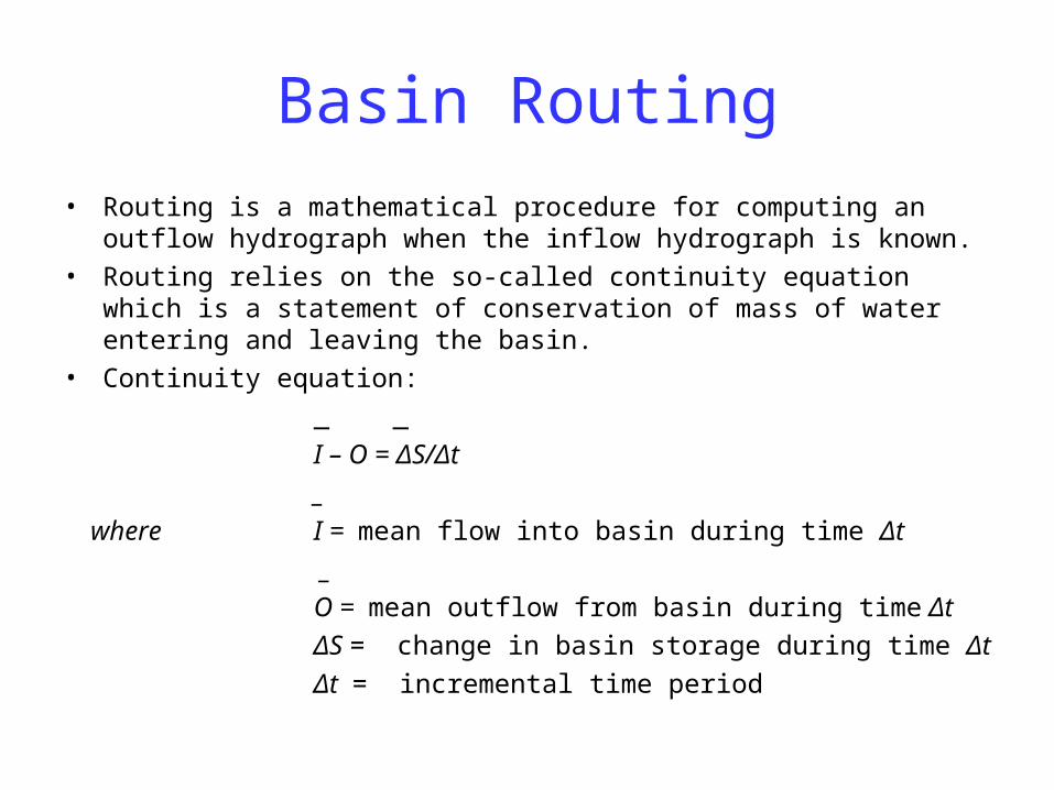
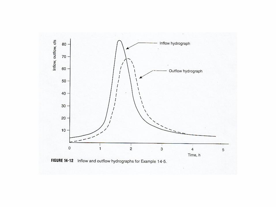
Basin Routing
• Routing is a mathematical procedure for computing an outflow hydrograph when the inflow hydrograph is known.
• Routing relies on the so-called continuity equation which is a statement of conservation of mass of water entering and leaving the basin.
• Continuity equation:
_ _
I – O = ΔS/Δt
_
where I = mean flow into basin during time Δt
_
O = mean outflow from basin during time Δt
ΔS = change in basin storage during time Δt
Δt = incremental time period
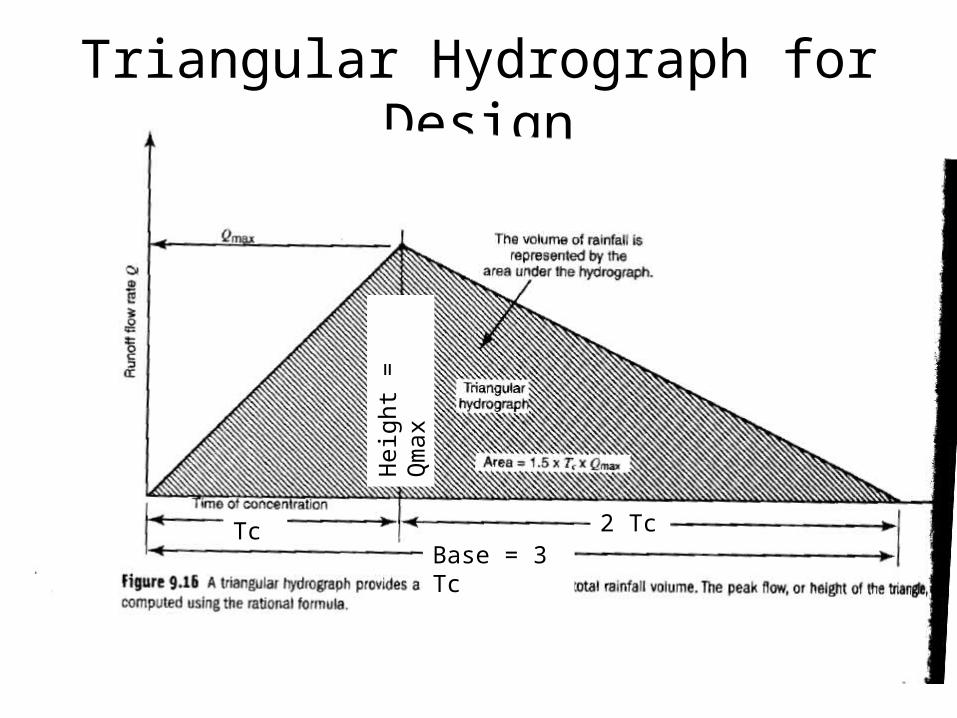
Triangular Hydrograph for Design
Base = 3 Tc2 TcTc
Hei
ght
= Q
max
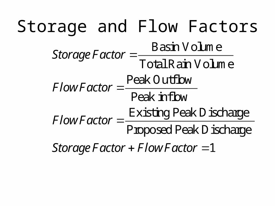
Storage and Flow FactorsBasin Volume
Total Rain VolumePeak Outflow
Peak inflow Existing Peak Discharge
Proposed Peak Discharge
1
Storage Factor
FlowFactor
FlowFactor
Storage Factor FlowFactor