Embed Size (px)
Citation preview

Stormwater Management Manual for Western Washington
Volume V Runoff Treatment BMPs
Prepared by: Washington State Department of Ecology
Water Quality Program
February 2005 Publication No. 05-10-33
(A revision of Publication No. 99-15)

Acknowledgments The 2001 edition of Volume V of Ecology's Stormwater Management Manual was developed with considerable assistance from a technical advisory committee. Their expertise was invaluable in developing this document. Ecology wishes to thank this committee for volunteering their time and sharing their expertise in this effort.
Advisory Member AffiliationTony Allen WA Department of Transportation Mark Blosser City of Olympia Michelle Cramer WA Department of Fish and Wildlife Roger James Consultant Chris Johnson City of Tacoma Louise Kulzer King County Surface Water Management Bill Leif Snohomish County Stormwater Management Jim Lenhart Stormwater Management Stan Miller Spokane County Gary Minton, PhD Resource Planning Associates Mel Oleson Boeing Co. Bill Peacock City of Spokane Kate Rhoads King County John Semrau Semrau Engineering & Surveying Joe Simmler Entranco Engineers Larry West HWA Geosciences, Inc. Ed Wiltsie Jerome W. Morrissette & Associates Jane Zimmerman
City of Everett
Department of Ecology Technical Leads Lisa Austin - 2001 update of this Volume Stan Ciuba - 2001 update Ed O’Brien - 2005 update
Technical Review and Editing Economic and Engineering Services, Inc. - 2001 update Charlene Witczak – 2005 update Kelsey Highfill – 2005 update
February 2005 Volume V – Runoff Treatment BMPs i

ii Volume V – Runoff Treatment BMPs February 2005

Table of Contents
Acknowledgments............................................................................................................... i
Chapter 1 - Introduction................................................................................................1-1
1.1 Purpose of this Volume................................................................................................ 1-1 1.2 Content and Organization of this Volume ................................................................... 1-1 1.3 How to Use this Volume.............................................................................................. 1-2 1.4 Runoff Treatment Facilities ......................................................................................... 1-2
1.4.1 General Considerations........................................................................................ 1-2 1.4.2 Maintenance......................................................................................................... 1-2 1.4.3 Treatment Methods .............................................................................................. 1-2
Chapter 2 - Treatment Facility Selection Process .......................................................2-1
2.1 Step-by-Step Selection Process for Treatment Facilities............................................. 2-1 2.2 Other Treatment Facility Selection Factors ................................................................. 2-8
Chapter 3 - Treatment Facility Menus.........................................................................3-1
3.1 Guide to Applying Menus............................................................................................ 3-1 3.2 Oil Control Menu......................................................................................................... 3-2 3.3 Phosphorus Treatment Menu ....................................................................................... 3-4 3.4 Enhanced Treatment Menu .......................................................................................... 3-6 3.5 Basic Treatment Menu................................................................................................. 3-9
Chapter 4 - General Requirements for Stormwater Facilities...................................4-1
4.1 Design Volume and Flow ............................................................................................ 4-1 4.1.1 Water Quality Design Storm Volume.................................................................. 4-1 4.1.2 Water Quality Design Flow Rate......................................................................... 4-1 4.1.3 Flows Requiring Treatment ................................................................................. 4-2
4.2 Sequence of Facilities .................................................................................................. 4-4 4.3 Setbacks, Slopes, and Embankments ........................................................................... 4-5
4.3.1 Setbacks ............................................................................................................... 4-5 4.3.2 Side Slopes and Embankments ............................................................................ 4-6
4.4 Facility Liners .............................................................................................................. 4-6 4.4.1 General Design Criteria ....................................................................................... 4-7 4.4.2 Design Criteria for Treatment Liners................................................................... 4-8 4.4.3 Design Criteria for Low Permeability Liner Options .......................................... 4-9
4.5 Hydraulic Structures .................................................................................................. 4-11 4.5.1 Flow Splitter Designs......................................................................................... 4-11 4.5.2 Flow Spreading Options .................................................................................... 4-16 4.5.3 Outfall Systems.................................................................................................. 4-22
4.6 Maintenance Standards for Drainage Facilities ......................................................... 4-30
February 2005 Volume V – Runoff Treatment BMPs iii

Chapter 5 - On-Site Stormwater Management............................................................5-1
5.1 Purpose......................................................................................................................... 5-1 5.2 Application................................................................................................................... 5-1 5.3 Best Management Practices for On-Site Stormwater Management ........................... 5-1
5.3.1 Dispersion and Soil Quality BMPs (Required for Manual Equivalency)............ 5-3 BMP T5.10 Downspout Dispersion ............................................................................ 5-3 BMP T5.11 Concentrated Flow Dispersion ................................................................ 5-9 BMP T5.12 Sheet Flow Dispersion .......................................................................... 5-11 BMP T5.13 Post-Construction Soil Quality and Depth ............................................ 5-13
5.3.2 Site Design BMPs.................................................................................................... 5-16 BMP T5.20 Preserving Natural Vegetation .............................................................. 5-16 BMP T5.21 Better Site Design.................................................................................. 5-18
5.3.3 Other Practices ................................................................................................... 5-22 BMP T5.30 Full Dispersion ...................................................................................... 5-22
Chapter 6 - Pretreatment...............................................................................................6-1
6.1 Purpose......................................................................................................................... 6-1 6.2 Application................................................................................................................... 6-1 6.3 Best Management Practices (BMPs) for Pretreatment ................................................ 6-1
BMP T6.10 Presettling Basin ............................................................................................. 6-1
Chapter 7 - Infiltration and Bio-infiltration Treatment Facilities ............................7-1
7.1 Purpose......................................................................................................................... 7-1 7.2 Application................................................................................................................... 7-1 7.3 General Considerations................................................................................................ 7-2 7.4 Best Management Practices (BMPs) for Infiltration and Bio-infiltration Treatment . 7-2
BMP T7.10 Infiltration Basins............................................................................................ 7-3 BMP T7.20 Infiltration Trenches........................................................................................ 7-4 BMP T7.30 Bio-infiltration Swale...................................................................................... 7-5
Chapter 8 - Sand Filtration Treatment Facilities........................................................8-1
8.1 Purpose......................................................................................................................... 8-1 8.2 Description................................................................................................................... 8-1 8.3 Performance Objectives ............................................................................................. 8-13 8.4 Applications and Limitations..................................................................................... 8-13 8.5 Site Suitability............................................................................................................ 8-13 8.6 Design Criteria ........................................................................................................... 8-14 8.7 Construction Criteria.................................................................................................. 8-18 8.8 Maintenance Criteria.................................................................................................. 8-18
BMP T8.10 Sand Filter Vault ........................................................................................... 8-20 BMP T8.20 Linear Sand Filter.......................................................................................... 8-22
Chapter 9 - Biofiltration Treatment Facilities.............................................................9-1
9.1 Purpose......................................................................................................................... 9-1
iv Volume V – Runoff Treatment BMPs February 2005

9.2 Applications ................................................................................................................. 9-1 9.3 Site Suitability.............................................................................................................. 9-1 9.4 Best Management Practices ......................................................................................... 9-2
BMP T9.10 Basic Biofiltration Swale ................................................................................ 9-2 BMP T9.20 Wet Biofiltration Swale ................................................................................ 9-21 BMP T9.30 Continuous Inflow Biofiltration Swale ......................................................... 9-24 BMP T9.40 Basic Filter Strip ........................................................................................... 9-25 BMP T9.50 Narrow Area Filter Strip ............................................................................... 9-27
Chapter 10 - Wetpool Facilities...................................................................................10-1
10.1 Purpose....................................................................................................................... 10-1 10.2 Application................................................................................................................. 10-1 10.3 Best Management Practices (BMPs) for Wetpool Facilities ..................................... 10-1
BMP T10.10 Wetponds - Basic and Large ....................................................................... 10-1 BMP T10.20 Wetvaults .................................................................................................. 10-19 BMP T10.30 Stormwater Treatment Wetlands .............................................................. 10-26 BMP T10.40 Combined Detention and Wetpool Facilities ............................................ 10-34
Chapter 11 - Oil and Water Separators .....................................................................11-1
11.1 Purpose of Oil and Water Separators......................................................................... 11-1 11.2 Description................................................................................................................. 11-1 11.3 Performance Objectives ............................................................................................. 11-5 11.4 Applications/Limitations............................................................................................ 11-5 11.5 Site Suitability............................................................................................................ 11-6 11.6 Design Criteria-General Considerations .................................................................... 11-6 11.7 Oil and Water Separator BMPs.................................................................................. 11-7
BMP T11.10 API (Baffle type) Separator Bay................................................................. 11-8 BMP T11.11 Coalescing Plate (CP) Separator Bay ....................................................... 11-10
Chapter 12 - Emerging Technologies .........................................................................12-1
12.1 Background................................................................................................................ 12-1 12.2 Ecology Role in Evaluating Emerging Technologies................................................ 12-1 12.3 Evaluation of Emerging Technologies....................................................................... 12-2 12.4 Acceptable Evaluation Protocols (TAPE and CTAPE) ............................................. 12-3 12.5 Assessing Levels of Development of Emerging Technologies ................................. 12-3 12.6 Examples of Emerging Technologies for Stormwater Treatment and Control ......... 12-4
12.6.1 Media Filters ...................................................................................................... 12-5 12.6.2 Amended Sand Filters........................................................................................ 12-8 12.6.3 Catch Basin Inserts (CBI) .................................................................................. 12-8 12.6.4 Manufactured Storm Drain Structures ............................................................. 12-10 12.6.5 High Efficiency Street Sweepers ..................................................................... 12-13
Volume V References .................................................................................................Ref-1
Appendix V-A Basic Treatment Receiving Waters....................................................A-1
February 2005 Volume V – Runoff Treatment BMPs v
Appendix V-B (Also published as Appendix III-D) Procedure for Conducting a Pilot Infiltration Test ....................................................................B-1
Appendix V-C Geotextile Specifications .....................................................................C-1
Appendix V-D Turbulence and Short-Circuiting Factor ..........................................D-1
vi Volume V – Runoff Treatment BMPs February 2005
Tables Table 2.1 Suggested Stormwater Treatment Options for New Development and
Redevelopment Projects ......................................................................................... 2-11 Table 2.2 Ability of Treatment Facilities to Remove Key Pollutants .................................... 2-12 Table 2.3 Screening Treatment Facilities Based on Soil Type............................................... 2-12 Table 3.1 Treatment Trains for Phosphorus Removal.............................................................. 3-5 Table 3.2 Treatment Trains for Dissolved Metals Removal..................................................... 3-8 Table 4.1 Treatment Facility Placement in Relation to Detention ........................................... 4-5 Table 4.2 Lining Types Recommended for Runoff Treatment Facilities................................. 4-8 Table 4.3 Compacted Till Liners .............................................................................................. 4-9 Table 4.4 Rock Protection at Outfalls .................................................................................... 4-17 Table 4.5 Maintenance Standards........................................................................................... 4-30 Table 8.1 Sand Medium Specification ................................................................................... 8-16 Table 8.2 Clay Liner Specifications ....................................................................................... 8-17 Table 9.1 Sizing Criteria........................................................................................................... 9-4 Table 9.2 Guide for Selecting Degree of Retardance ............................................................. 9-11 Table 9.3 Grass Seed Mixes Suitable for Biofiltration Swale Treatment Areas .................... 9-18 Table 9.4 Groundcovers And Grasses Suitable for the Upper Side Slopes of a Biofiltration
Swale in Western Washington................................................................................ 9-18 Table 9.5 Recommended Plants for Wet Biofiltration Swale ................................................ 9-23 Table 10.1 Emergent Wetland Plant Species Recommended for Wetponds.......................... 10-14 Table 10.2 Distribution of Depths in Wetland Cell................................................................ 10-29 Table C.1 Geotextile Properties for Underground Drainage.................................................... C-1 Table C-2 Geotextile for Underground Drainage Filtration Properties.................................... C-2 Table C-3 Geotextile Strength Properties for Impermeable Liner Protection.......................... C-2
February 2005 Volume V – Runoff Treatment BMPs vii

Figures Figure 2.1 Treatment Facility Selection Flow Chart ................................................................ 2-2 Figure 4.1 Flow Splitter, Option A......................................................................................... 4-14 Figure 4.2 Flow Splitter, Option B ......................................................................................... 4-15 Figure 4.3 Flow Spreader Option A: Anchored Plate............................................................. 4-19 Figure 4.4 Flow Spreader Option B: Concrete Sump Box ..................................................... 4-20 Figure 4.5 Flow Spreader Option C: Notched Curb Spreader................................................ 4-21 Figure 4.7 Pipe/Culvert Outfall Discharge Protection............................................................ 4-24 Figure 4.8 Flow Dispersal Trench .......................................................................................... 4-25 Figure 4.9 Alternative Flow Dispersal Trench ....................................................................... 4-26 Figure 4.10 Gabion Outfall Detail ............................................................................................ 4-27 Figure 4.11 Diffuser TEE (an example of energy dissipating end feature).............................. 4-28 Figure 4.12 Fish Habitat Improvement at New Outfalls .......................................................... 4-29 Figure 5.1 Typical Dispersion Trench ...................................................................................... 5-5 Figure 5.2 Standard Dispersion Trench with Notched Grade Board........................................ 5-6 Figure 5.3 Typical Downspout Splashblock Dispersion .......................................................... 5-7 Figure 5.4 Typical Concentrated Flow Dispersion for Steep Driveways ............................... 5-10 Figure 5.5 Sheet Flow Dispersion for Driveways................................................................... 5-12 Figure 8.1 Sand Filtration Basin Preceded by Presettling Basin (Variation of a Basic
Sand Filter) ............................................................................................................. 8-2 Figure 8.2 Sand Filter with Pretreatment Cell .......................................................................... 8-3 Figure 8.3 Sand Filter with Level Spreader.............................................................................. 8-5 Figure 8.4a Flow Splitter Option A............................................................................................ 8-7 Figure 8.4b Flow Splitter Option B ............................................................................................ 8-8 Figure 8.5 Example Isolation/Diversion Structure ................................................................... 8-9 Figure 8.6a Sand Filter Vault ................................................................................................... 8-10 Figure 8.6b Sand Filter Vault (cont)......................................................................................... 8-11 Figure 8.7 Linear Sand Filter.................................................................................................. 8-12 Figure 9.1 Typical Swale Section ............................................................................................. 9-2 Figure 9.2 Biofiltration Swale Underdrain Detail .................................................................... 9-5 Figure 9.3 Biofiltration Swale Low-Flow Drain Detail............................................................ 9-5 Figure 9.4 Swale Dividing Berm .............................................................................................. 9-6 Figure 9.5 Geometric Formulas for Common Swale Shapes ................................................... 9-8 Figure 9.6a Ratio of SBUH Peak/WQ Flow............................................................................. 9-10 Figure 9.6b Ratio of SBUH Peak/WQ Flow............................................................................. 9-10
viii Volume V – Runoff Treatment BMPs February 2005

Figure 9.7 The Relationship of Manning’s n with VR for Various Degrees of Flow Retardance (A-E) ......................................................................................... 9-12
Figure 9.8 Biofiltration Swale Access Features...................................................................... 9-20 Figure 9.9 Typical Filter Strip ................................................................................................ 9-25 Figure 9.10 Filter Strip Lengths for Narrow Right-of-Way ..................................................... 9-28 Figure 10.1a Wetpond ................................................................................................................ 10-2 Figure 10.1b Wetpond ................................................................................................................ 10-3 Figure 10.2 Headwater Depth for Smooth Interior Pipe Culverts with Inlet Control ............ 10-15 Figure 10.3 Headwater Depth for Corrugated Pipe Culverts with Inlet Control .................... 10-16 Figure 10.4 Critical Depth of Flow for Circular Culverts ...................................................... 10-17 Figure 10.5 Circular Channel Ratios ...................................................................................... 10-18 Figure 10.6 Wetvault .............................................................................................................. 10-20 Figure 10.7 Stormwater Wetland — Option One ................................................................... 10-29 Figure 10.8 Stormwater Wetland — Option Two .................................................................. 10-30 Figure 10.9 Combined Detention and Wetpond ..................................................................... 10-36 Figure 10.10 Combined Detention and Wetpond (Continued)................................................. 10-37 Figure 10.11 Alternative Configurations of Detention and Wetpool Areas ............................. 10-38 Figure 11.1 API (Baffle Type) Separator ................................................................................. 11-2 Figure 11.2 Coalescing Plate Separator.................................................................................... 11-3 Figure 11.3 Spill Control Separator (not for oil treatment) ...................................................... 11-4 Figure 12.1 Vertical Media Filter ............................................................................................. 12-5 Figure 12.2 - Vortex-enhanced Sedimentation and Media Filtration ...................................... 12-10 Figure 12.3 Screen Separator.................................................................................................. 12-11 Figure 12.4 Engineered Cylindrical........................................................................................ 12-12 Figure D.1 Recommended Values of F for Various Values of vH/Vt ...................................... D-1
February 2005 Volume V – Runoff Treatment BMPs ix


Chapter 1 - Introduction 1.1 Purpose of this Volume
Best Management Practices (BMPs) are schedules of activities, prohibitions of practices, maintenance procedures, managerial practices, or structural features that prevent or reduce adverse impacts to waters of Washington State. As described in Volume I of this stormwater manual, BMPs for long-term management of stormwater at developed sites can be divided into three main categories:
• BMPs addressing the amount and timing of stormwater flows;
• BMPs addressing prevention of pollution from potential sources; and
• BMPs addressing treatment of runoff to remove sediment and other pollutants.
This volume of the stormwater manual focuses on the third category, treatment of runoff to remove sediment and other pollutants at developed sites. The purpose of this volume is to provide guidance for selection, design and maintenance of permanent runoff treatment facilities.
BMPs with respect to controlling stormwater flows and control of pollutant sources are presented in Volumes III and IV, respectively.
1.2 Content and Organization of this Volume Volume V of the stormwater manual contains 12 chapters. Chapter 1 serves as an introduction and summarizes available options for treatment of stormwater. Chapter 2 outlines a step-by-step process for selecting treatment facilities for new development and redevelopment projects. Chapter 3 presents treatment facility “menus” that are used in applying the step-by-step process presented in Chapter 2. These menus cover different treatment needs that are associated with different sites. Chapter 4 discusses general requirements for treatment facilities. Chapter 5 presents information regarding on-site stormwater management BMPs. These BMPs are intended to infiltrate, disperse, or contain runoff on site, as well as to provide treatment. Chapters 6 through 11 provide detailed information regarding specific types of treatment identified in the menus. Chapter 12 discusses special considerations for emerging technologies for stormwater treatment.
The Appendices to this volume contain more detailed information on selected topics described in the various chapters.
February 2005 Volume V – Runoff Treatment BMPs 1-1

1.3 How to Use this Volume This volume should be consulted to select specific BMPs for runoff treatment for inclusion in Stormwater Site Plans (see Volume I). After the Minimum Requirements have been identified from Volume I, this volume can be used to select specific treatment facilities for permanent use at developed sites, and as an aid in designing and constructing these facilities.
1.4 Runoff Treatment Facilities 1.4.1 General Considerations
Runoff treatment facilities are designed to remove pollutants contained in stormwater runoff. The pollutants of concern include sand, silt, and other suspended solids; metals such as copper, lead, and zinc; nutrients (e.g., nitrogen and phosphorous); certain bacteria and viruses; and organics such as petroleum hydrocarbons and pesticides. Methods of pollutant removal include sedimentation/settling, filtration, plant uptake, ion exchange, adsorption, and bacterial decomposition. Floatable pollutants such as oil, debris, and scum can be removed with separator structures.
1.4.2 Maintenance
Maintenance is required for all types of runoff treatment facilities. See Section 4.6 for maintenance standards for the treatment facilities discussed in this volume.
1.4.3 Treatment Methods
Methods used for runoff treatment facilities and common terms used in runoff treatment are discussed below:
• Wetpools. Wetpools provide runoff treatment by allowing settling of particulates during quiescent conditions (sedimentation), by biological uptake, and by vegetative filtration. Wetpools may be single-purpose facilities, providing only runoff treatment, or they may be combined with a detention pond or vault to also provide flow control. If combined, the wetpool facility can often be stacked under the detention facility with little further loss of development area.
• Biofiltration. Biofiltration uses vegetation in conjunction with slow and shallow-depth flow for runoff treatment. As runoff passes through the vegetation, pollutants are removed through the combined effects of filtration, infiltration, and settling. These effects are aided by the reduction of the velocity of stormwater as it passes through the biofilter. Biofiltration facilities include swales that are designed to
1-2 Volume V – Runoff Treatment BMPs February 2005

convey and treat concentrated runoff at shallow depths and slow velocities, and filter strips that are broad areas of vegetation for treating sheet flow runoff.
• Oil/Water Separation. Oil/water separators remove oil floating on the top of the water. There are two general types of separators - the American Petroleum Institute (API) separators and coalescing plate (CP) separators. Both use gravity to remove floating and dispersed oil. API separators, or baffle separators, are generally composed of three chambers separated by baffles. The efficiency of these separators is dependent on detention time in the center, or detention chamber, and on droplet size. CP separators use a series of parallel plates, which improve separation efficiency by providing more surface area, thus reducing the space needed for the separator. Oil/water separators must be located off-line from the primary conveyance/detention system, bypassing flows greater than the water quality design flow. Other devices/facilities that may be used for removal of oil include catch basin inserts and linear sand filters. Oil control devices/facilities should always be placed upstream of other treatment facilities and as close to the source of oil generation as possible.
• Pretreatment. Presettling basins are often used to remove sediment from runoff prior to discharge into other treatment facilities. Basic treatment facilities, listed in Step 6 – Figure 2.1, can also be used to provide pretreatment. Pretreatment often must be provided for filtration and infiltration facilities to protect them from clogging or to protect ground water. Appropriate pretreatment devices include a pre-settling basin, wet pond/vault, biofilter, constructed wetland, or oil/water separator.
• Infiltration. Infiltration refers to the use of the filtration, adsorption, and biological decomposition properties of soils to remove pollutants. Infiltration can provide multiple benefits including pollutant removal, peak flow control, ground water recharge, and flood control. However, one condition that can limit the use of infiltration is the potential adverse impact on ground water quality. To adequately address the protection of ground water when evaluating infiltration it is important to understand the difference between soils that are suitable for runoff treatment and soils only suitable for flow control. Sufficient organic content and sorption capacity to remove pollutants must be present for soils to provide runoff treatment. Examples are silty and sandy loams. Coarser soils, such as gravelly sands, can provide flow control but are not suitable for providing runoff treatment. The use of coarser soils to provide flow control for runoff from pollutant generating surfaces must always be preceded by treatment to protect ground water quality. Thus, there will be instances when soils are suitable for treatment but not flow control, and vice versa.
February 2005 Volume V – Runoff Treatment BMPs 1-3

• Filtration. A relatively new application of a pollutant removal system for stormwater is the use of various media such as sand, perlite, zeolite, and carbon, to remove low levels of total suspended solids (TSS). Specific media such as activated carbon or zeolite can remove hydrocarbons and soluble metals. Filter systems can be configured as basins, trenches or the novel cartridges.
• “Emerging Technologies.” Emerging technologies are new technologies that have not been evaluated using approved protocols, but for which preliminary data indicate that they may provide a desirable level of stormwater pollutant removal. They have not been evaluated in sufficient detail to be acceptable as stand alone BMPs for general usage in new development or redevelopment situations requiring Basic Treatment. In the instances noted in Chapter 3, a few emerging technologies are allowed to help remove metals, hydrocarbons, and nutrients. Otherwise, their use is restricted in accordance with their level of development as explained in Chapter 12. The recommendations for use of these emerging technologies will change as we collect more data on their performance. Updated recommendations on their use will be posted to the Ecology website. Meanwhile, emerging technologies can also be used for retrofit situations.
• “On-line” Systems. Most treatment facilities can be designed as “On-line” systems with flows above the water quality design flow or volume simply passing through the facility with lesser or no pollutant removal efficiency. However, it is sometimes desirable to restrict flows to treatment facilities and bypass the remaining higher flows around them. These are called “Off-line” systems. An example of an on-line system is a wetpool that maintains a permanent pool of water for runoff treatment purposes.
• Design Flow. For information on determining the design storm and flows for sizing treatment facilities refer to Chapter 4 of this volume.
1-4 Volume V – Runoff Treatment BMPs February 2005

Chapter 2 - Treatment Facility Selection Process This chapter describes a step-by-step process for selecting the type of treatment facilities that will apply to individual projects. Physical features of sites that are applicable to treatment facility selection are also discussed. Refer to Chapter 3 for additional detail on the four treatment menus - oil control treatment, phosphorous treatment, enhanced treatment, and basic treatment.
2.1 Step-by-Step Selection Process for Treatment Facilities Please refer to Figure 2.1. Use the step-by-step process outlined below to determine the type of treatment facilities applicable to the project.
Step 1: Determine the Receiving Waters and Pollutants of Concern Based on Off-Site Analysis
To obtain a more complete determination of the potential impacts of a stormwater discharge, Ecology encourages local governments to require an Off-site Analysis similar to that in Chapter 2 of Volume 1. Even without an off-site analysis requirement, the project proponent must determine the natural receiving water for the stormwater drainage from the project site (ground water, wetland, lake, stream, or salt water). This is necessary to determine the applicable treatment menu from which to select treatment facilities. The identification of the receiving water should be verified by the local government agency with review responsibility. If the discharge is to the local municipal storm drainage system, the receiving water for the drainage system must be determined.
The local government should verify whether any type of water quality management plans and/or local ordinances or regulations have established specific requirements for that (those) receiving waters. Examples of plans to be aware of include: • Watershed or Basin Plans: These can be developed to cover a wide
variety of geographic scales (e.g., Water Resource Inventory Areas, or sub-basins of a few square miles), and can be focused solely on establishing stormwater requirements (e.g., “Stormwater Basin Plans”), or can address a number of pollution and water quantity issues, including urban stormwater (e.g., Puget Sound Non-Point Action Plans).
• Water Clean-up Plans: These plans are written to establish a Total Maximum Daily Load (TMDL) of a pollutant or pollutants in a specific receiving water or basin, and to identify actions necessary to remain below that maximum loading. The plans may identify discharge limitations or management limitations (e.g., use of specific treatment facilities) for stormwater discharges from new and redevelopment projects.
February 2005 Volume V – Runoff Treatment BMPs 2-1

2-2 Volume V – Runoff Treatment BMPs February 2005
Figure 2.1 – Treatment Facility Selection Flow Chart
Step 1: Determine Receiving Waters and Pollutants of Concern
Perform Off-site•
Analysis
Apply Oil Control Facility Yes Step 2: Determine if API Separator • an Oil Control CP Separator • Facility is Required Linear Sand Filter •
No Catch Basin Insert •
Apply Infiltration • Infiltration Basin • Infiltration Trench • Bioinfiltration
Swale
Apply Pretreatment • Presettling Basin
or • Any Basic
Treatment BMP
Yes
Yes
Yes
No
Step 3: Determine if Infiltration for Pollutant Removal is Apply Phosphorus Practicable Control Facility No Large Sand Filter •
Amended Sand • Step 4: Determine if Filter Phosphorus Control Large Wetpond • Is Required Media Filter •
Two Facility •
Treatment Train Step 5: Determine if Enhanced Treatment Is Required No
Apply an Enhanced Treatment Facility
Step 6: • Large Sand Filter
Apply a Basic Treatment Facility
• Amended Sand Filter
• Treatment Wetland • Biofiltration
Swales • Compost-amended Filter Strip
• Filter Strips • Basic Wetpond • Wetvault • Two Facility
Treatment Train • Treatment Wetlands • Bioretention
• Combined Detention/Wetpool
• Ecology Embankment1
• Sand Filters • Bioretention • Ecy Embankment1 • StormFilter –ZPG1
1 See Section 3.5, Chapter 3 of Volume V for more information

• Groundwater Management Plans (Wellhead Protection Plans): To
protect groundwater quality and/or quantity, these plans may identify actions required of stormwater discharges.
• Lake Management Plans: These plans are developed to protect lakes from eutrophication due to inputs of phosphorus from the drainage basin. Control of phosphorus from new development is a likely requirement in any such plans.
An analysis of the proposed land use(s) of the project should also be used to determine the stormwater pollutants of concern. Table 2.1 lists the pollutants of concern from various land uses. Refer to this table for examples of treatment options after determining whether “basic,” “enhanced,” or “phosphorus” treatment requirements apply to the project. Those decisions are made in the steps below.
Step 2: Determine if an Oil Control Facility/Device is Required
The use of oil control devices and facilities is dependent upon the specific land use proposed for development.
The Oil Control Menu (Chapter 3, Section 3.2) applies to projects that have “high-use sites.” High-use sites are those that typically generate high concentrations of oil due to high traffic turnover or the frequent transfer of oil. High-use sites include:
• An area of a commercial or industrial site subject to an expected average daily traffic (ADT) count equal to or greater than 100 vehicles per 1,000 square feet of gross building area,
• An area of a commercial or industrial site subject to petroleum storage and transfer in excess of 1,500 gallons per year, not including routinely delivered heating oil,
• An area of a commercial or industrial site subject to parking, storage or maintenance of 25 or more vehicles that are over 10 tons gross weight (trucks, buses, trains, heavy equipment, etc.),
• A road intersection with a measured average daily traffic (ADT) count of 25,000 vehicles or more on the main roadway and 15,000 vehicles or more on any intersecting roadway, excluding projects proposing primarily pedestrian or bicycle use improvements.
Note: The traffic count can be estimated using information from “Trip Generation,” published by the Institute of Transportation Engineers, or from a traffic study prepared by a professional engineer or transportation specialist with experience in traffic estimation.
February 2005 Volume V – Runoff Treatment BMPs 2-3

Please refer to the Oil Control Menu for a listing of oil control facility options. Then see Chapter 11 of this volume for guidance on the proper selection of options and design details.
Note that some land use types require the use of a spill control (SC-type) oil/water separator. Those situations are described in Volume IV and are separate from this treatment requirement. While a number of activities may be required to use spill control (SC-type) separators, only a few will necessitate an American Petroleum Institute (API) or a coalescing plate (CP)-type separators for treatment. The following urban land uses are likely to have areas that fall within the definition of “high-use sites” or have sufficient quantities of free oil present that can be treated by an API or CP-type oil/water separator:
• Industrial Machinery and Equipment, and Railroad Equipment Maintenance
• Log Storage and Sorting Yards
• Aircraft Maintenance Areas
• Railroad Yards
• Fueling Stations
• Vehicle Maintenance and Repair
• Construction Businesses (paving, heavy equipment storage and maintenance, storage of petroleum products)
If oil control is required for the site, please refer to the General Requirements in Chapter 4. These requirements may affect the design and placement of facilities on the site (e.g., flow splitting).
If an Oil Control Facility is required, select and apply an Oil Control Facility. Please refer to the Oil Control Menu in Chapter 3, Section 3.2. After selecting an Oil Control Facility, proceed to Step 3.
If an Oil Control Facility is not required, proceed directly to Step 3.
Step 3: Determine if Infiltration for Pollutant Removal is Practicable
Please check the infiltration treatment design criteria in Chapter 3 of Volume III. Infiltration can be effective at treating stormwater runoff, but soil properties must be appropriate to achieve effective treatment while not adversely impacting ground water resources. The location and depth to bedrock, the water table, or impermeable layers (such as glacial till), and the proximity to wells, foundations, septic tank drainfields, and unstable
2-4 Volume V – Runoff Treatment BMPs February 2005

slopes can preclude the use of infiltration. Infiltration treatment facilities must be preceded by a pretreatment facility, such as a presettling basin or vault, to reduce the occurrence of plugging. Any of the basic treatment facilities, and detention ponds designed to meet flow control requirements, can also be used for pre-treatment. If an oil/water separator is necessary for oil control, it can also function as the pre-settling basin as long as the influent suspended solids concentrations are not high. However, frequent inspections are necessary to determine when accumulated solids exceed the 6-inch depth at which clean-out is recommended (See Chapter 4).
If infiltration is planned, please refer to the General Requirements in Chapter 4. They can affect the design and placement of facilities on your site. For non-residential developments, if your infiltration site is within ¼ mile of a fish-bearing stream, a tributary to a fish-bearing stream, or a lake, please refer to the Enhanced Treatment Menu (Chapter 3, Section 3.4). Read the “Where Applied” paragraph in that section to determine if the Enhanced Treatment Menu applies to part of, or all of the site. If it does apply, read the Note under “Infiltration with appropriate pretreatment” to identify special pretreatment needs. If your infiltration site is within ¼ mile of a phosphorus-sensitive receiving water, please refer to the Phosphorus Treatment Menu (Chapter 3, Section 3.3) for special pretreatment needs.
Note: Infiltration through soils that do not meet the site suitability criteria in Chapter 3 of Volume III is allowable as a flow control BMP. However, the infiltration facility must be preceded by at least a basic treatment facility. Following a basic treatment facility (or an enhanced treatment or a phosphorus treatment facility in accordance with the previous paragraph), infiltration through the bottom of a detention/retention facility for flow control can also be acceptable as a way to reduce direct discharge volumes to streams and the size of the facility.
If infiltration is practicable, select and apply pretreatment and an infiltration facility.
If infiltration is not practicable, proceed to Step 4.
Step 4: Determine if Control of Phosphorous is Required
Please refer to the plans, ordinances, and regulations identified in Step 1 as sources of information.
The requirement to provide phosphorous control is determined by the local government with jurisdiction, the Department of Ecology, or the USEPA. The local government may have developed a management plan and implementing ordinances or regulations for control of phosphorus from new development and redevelopment for the receiving water(s) of the
February 2005 Volume V – Runoff Treatment BMPs 2-5

stormwater drainage. The local government can use the following sources of information for pursuing plans and implementing ordinances and/or regulations:
• Those waterbodies reported under section 305(b) of the Clean Water Act, and designated as not supporting beneficial uses due to phosphorous;
• Those listed in Washington State's Nonpoint Source Assessment required under section 319(a) of the Clean Water Act due to nutrients.
If phosphorus control is required, select and apply a phosphorous treatment facility. Please refer to the Phosphorus Treatment Menu in Chapter 3 Section 3.3. Select an option from the menu after reviewing the applicability and limitations, site suitability, and design criteria of each for compatibility with the site. You may also use Tables 2.1 through 2.3 as an initial screening of options.
If you have selected a phosphorus treatment facility, please refer to the General Requirements in Chapter 4. They may affect the design and placement of the facility on the site.
Note: Project sites subject to the Phosphorus Treatment requirement could also be subject to the Enhanced Treatment requirement (see Step 5). In that event, apply a facility or a treatment train that is listed in both the Enhanced Treatment Menu and the Phosphorus Treatment Menu.
If phosphorus treatment is not required for the site, proceed to Step 5.
Step 5: Determine if Enhanced Treatment is Required
Enhanced treatment is required for the following project sites that discharge to fish-bearing streams, lakes, or to waters or conveyance systems tributary to fish-bearing streams or lakes:
Industrial project sites, Commercial project sites, Multi-family project sites, and High AADT roads as follows:
Within Urban Growth Management Areas: • Fully controlled and partially controlled limited access
highways with Annual Average Daily Traffic (AADT) counts of 15,000 or more
• All other roads with an AADT of 7,500 or greater
2-6 Volume V – Runoff Treatment BMPs February 2005

Outside of Urban Growth Management Areas: • Roads with an AADT of 15,000 or greater unless discharging
to a 4th Strahler order stream or larger; • Roads with an AADT of 30,000 or greater if discharging to a
4th Strahler order stream or larger (as determined using 1:24,000 scale maps to delineate stream order).
However, such sites listed above that discharge directly (or, indirectly through a municipal storm sewer system) to Basic Treatment Receiving Waters (Appendix V-A), and areas of the above-listed project sites that are identified as subject to Basic Treatment requirements (see Step 6) are also not subject to Enhanced Treatment requirements. For developments with a mix of land use types, the Enhanced Treatment requirement shall apply when the runoff from the areas subject to the Enhanced Treatment requirement comprises 50% or more of the total runoff within a threshold discharge area.
If the project must apply Enhanced Treatment, select and apply an appropriate Enhanced Treatment facility. Please refer to the Enhanced Treatment Menu in Chapter 3, Section 3.4. Select an option from the menu after reviewing the applicability and limitations, site suitability, and design criteria of each for compatibility with the site. You may also use Tables 2.1 through 2.3 for an initial screening of options.
Note: Project sites subject to the Enhanced Treatment requirement could also be subject to a phosphorus removal requirement if located in an area designated for phosphorus control. In that event, apply a facility or a treatment train that is listed in both the Enhanced Treatment Menu and the Phosphorus Treatment Menu. If you have selected an Enhanced Treatment facility, please refer to the General Requirements in Chapter 4. They may affect the design and placement of the facility on the site.
If Enhanced Treatment does not apply to the site, please proceed to Step 6.
Step 6: Select a Basic Treatment Facility
The Basic Treatment Menu is generally applied to:
• Project sites that discharge to the ground (see Step 3), UNLESS:
− The soil suitability criteria for infiltration treatment are met (see Chapter 3 of Volume III), or
− The project uses infiltration strictly for flow control – not treatment - and the discharge is within ¼-mile of a phosphorus sensitive lake (use the Phosphorus Treatment Menu), or within ¼ mile of a fish-bearing stream, or a lake (use the Enhanced Treatment Menu).
February 2005 Volume V – Runoff Treatment BMPs 2-7
• Residential projects not otherwise needing phosphorus control in Step 4 as designated by USEPA, the Department of Ecology, or a local government; and
• Project sites discharging directly to salt waters, river segments, and lakes listed in Appendix V-A; and
• Project sites that drain to streams that are not fish-bearing, or to waters not tributary to fish-bearing streams;
• Landscaped areas of industrial, commercial, and multi-family project sites, and parking lots of industrial and commercial project sites, dedicated solely to parking of employees’ private vehicles that do not involve any other pollution-generating sources (e.g., industrial activities, customer parking, storage of erodible or leachable material, wastes or chemicals). For developments with a mix of land use types, the Basic Treatment requirement shall apply when the runoff from the areas subject to the Basic Treatment requirement comprises 50% or more of the total runoff within a threshold discharge area.
Please refer to the Basic Treatment Menu in Chapter 3, Section 3.5. Select an option from the menu after reviewing the applicability and limitations, site suitability, and design criteria of each for compatibility with the site. You may also use Tables 2.1 through 2.3 as an initial screening of options.
After selecting a Basic Treatment Facility, please refer to the General Requirements in Chapter 4. They may affect the design and placement of the facility on the site.
You have completed the treatment facility selection process.
2.2 Other Treatment Facility Selection Factors The selection of a treatment facility should be based on site physical factors and pollutants of concern. The requirements for use of Enhanced Treatment or Phosphorus Treatment represent facility selection based on pollutants of concern. Even if the site is not subject to those requirements, try to choose a facility that is more likely to do a better job removing the types of pollutants generated on the site. The types of site physical factors that influence facility selection are summarized below.
Pollutants of Concern (Table 2.1 and Table 2.2)
Table 2.1 summarizes the pollutants of concern and those land uses that are likely to generate pollutants. It also provides suggested basic and enhanced treatment options for each land use. For example, oil and grease are the expected pollutants from an uncovered fueling station. Using Table 2.1, a combination of an oil/water separator and a biofilter could be considered as the basic treatment for runoff from uncovered fueling
2-8 Volume V – Runoff Treatment BMPs February 2005
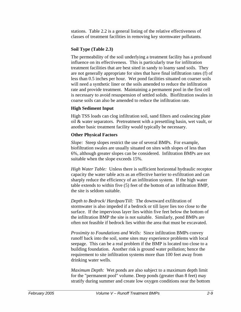
stations. Table 2.2 is a general listing of the relative effectiveness of classes of treatment facilities in removing key stormwater pollutants.
Soil Type (Table 2.3) The permeability of the soil underlying a treatment facility has a profound influence on its effectiveness. This is particularly true for infiltration treatment facilities that are best sited in sandy to loamy sand soils. They are not generally appropriate for sites that have final infiltration rates (f) of less than 0.5 inches per hour. Wet pond facilities situated on coarser soils will need a synthetic liner or the soils amended to reduce the infiltration rate and provide treatment. Maintaining a permanent pool in the first cell is necessary to avoid resuspension of settled solids. Biofiltration swales in coarse soils can also be amended to reduce the infiltration rate.
High Sediment Input High TSS loads can clog infiltration soil, sand filters and coalescing plate oil & water separators. Pretreatment with a presettling basin, wet vault, or another basic treatment facility would typically be necessary.
Other Physical Factors Slope: Steep slopes restrict the use of several BMPs. For example, biofiltration swales are usually situated on sites with slopes of less than 6%, although greater slopes can be considered. Infiltration BMPs are not suitable when the slope exceeds 15%.
High Water Table: Unless there is sufficient horizontal hydraulic receptor capacity the water table acts as an effective barrier to exfiltration and can sharply reduce the efficiency of an infiltration system. If the high water table extends to within five (5) feet of the bottom of an infiltration BMP, the site is seldom suitable.
Depth to Bedrock/ Hardpan/Till: The downward exfiltration of stormwater is also impeded if a bedrock or till layer lies too close to the surface. If the impervious layer lies within five feet below the bottom of the infiltration BMP the site is not suitable. Similarly, pond BMPs are often not feasible if bedrock lies within the area that must be excavated.
Proximity to Foundations and Wells: Since infiltration BMPs convey runoff back into the soil, some sites may experience problems with local seepage. This can be a real problem if the BMP is located too close to a building foundation. Another risk is ground water pollution; hence the requirement to site infiltration systems more than 100 feet away from drinking water wells.
Maximum Depth: Wet ponds are also subject to a maximum depth limit for the "permanent pool" volume. Deep ponds (greater than 8 feet) may stratify during summer and create low oxygen conditions near the bottom
February 2005 Volume V – Runoff Treatment BMPs 2-9

resulting in re-release of phosphorus and other pollutants back into the water.
2-10 Volume V – Runoff Treatment BMPs February 2005

Table 2.1 – Suggested Stormwater Treatment Options for New Development and Redevelopment Projects
Pollutant Sources
Pollutants of Concern Basic Treatment Enhanced Treatment Phosphorus Treatment1
ROOFS: Com/Ind
Metal Zn STW/INF LSF/ASF/STW/INF Vents &
Emissions(2)O & G, TSS, Organics
OWS/CBI + BF/WP/STW OWS/CBI + INF/ASF/STW/LSF
OWS/CBI + INF/LWP/LSF
PARKING LOT/DRIVEWAY: >High-use Site High O & G, TSS,
Cu, Zn, PAH OWS/CBI/LinSF + BF/WP/STW
OWS/CBI + BF/WP/WV + SF
OWS/CBI + LSF/LWP, or OWS/CBI + BF/WP/WV+ SF
<High-use O & G, TSS BF/WP/STW BF/WP/STW/WV + SF LSF/LWP, or BF/WP/WV+SFSTREETS/HIGHWAYS: Arterials/H’ways O & G, TSS, Cu,
Zn, PAH BF/WP/WV/STW INF/LSF/ASF/STW, or
BF/WV/WP + SF INF/LSF/LWP, or BF/WV + SF
Residential Collectors
Low O & G, TSS, Cu, Zn
BF/WP/STW/INF Not Applicable
INF/LSF/LWP, or BF/WV + SF
High Use Site Intersections
High O & G, TSS, Cu, Zn, PAH
OWS + BF/WP/WV/LinSF OWS + BF/WV+SF, or OWS + LinSF+BF
OWS + ASF, or OWS + LinSF + Filter Strip
OTHER SOURCES: Industrial/ Commercial Development
O & G, TSS, Cu, Zn
WP/WV/SF/STW LSF/ASF/STW, or BF/WP/WV + SF
LSF/ASF/LWP, or BF/WP/STW + SF
Residential Development
TSS, Pest/ Herbicides Nutrients
INF/BF/WP/SF/STW Not Applicable INF/LSF/LWP, or BF/WP/STW + SF
Large PGPS TSS, Nutrients, Pest/Herbicides
WP/STW/SF Not Applicable LSF/LWP, or WP/STW + SF
Uncovered Fueling Stations:
High conc. O & G OWS + BF/WP OWS + LSF/ASF, or OWS+LinSF+Filter strip
OWS + LSF/ASF, or OWS+LinSF+ Filter strip
Industrial Yards High O & G, TSS, Metals, PAH
OWS/CBI + BF/WP, or PSB/WV + OWS/CBI + BF/WP
OWS/CBI + LSF/ASF/STW, or OWS/CBI + BF/WP/WV + SF
OWS/CBI + LSF/ASF/LWP, or OWS/CBI + BF/WP/STW + SF
Metals, TSS, PAH BF/WP/STW , or PSB +BF/WP/STW
LSF/ASF/STW, or BF/WP/WV + SF
LSF/ASF/LWP, or BF/WP/STW + SF
Notes: 1 Though phosphorus is not typically listed as a pollutant of concern, it is present in most urban runoff situations. It becomes
a pollutant of concern when identified by USEPA, the Department of Ecology, or a local government in a local management plan and when requirements are established in local ordinance or rules. If phosphorus is identified as a pollutant of concern, consider the treatment options listed here.
2 Application of effective source control measures is the preferred approach for pollutant reduction. Where source conrol measures are not used, or where they are ineffective, stormwater treatment is necessary.
Legend: ASF = Amended Sand Filter INF = Infiltration BF = Biofilter (includes swales and strips) CBI = Catch Basin Insert, if applicable (See Chapter 10) Cu = Copper Com/Ind = Commercial or industrial LSF = Large Sand Filter LinSF = Linear Sand Filter LWP = Large Wet Pond O & G = Oil and Grease OWS = Oil & Water Separator PAH = Polycyclic Aromatic Hydrocarbons PSB = Presettling Basin PGPS = Pollution-generating pervious surface SF = Sand Filter STW = Stormwater Treatment Wetland TSS = Total Suspended Solids WP = Wet Pond WV = Wetvault Zn = Zinc / = or : The slashes between the abbreviations for treatment types are intended to indicate equivalent treatment options Additional Notes: If a detention facility is needed for flow control to meet Min. Requirement #7 or #8, a combined detention and Wetpool (Basic or Large depending upon the discharge circumstance) facility should be considered.
February 2005 Volume V – Runoff Treatment BMPs 2-11
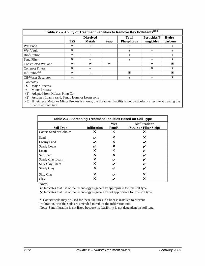
Table 2.2 – Ability of Treatment Facilities to Remove Key Pollutants(1) (3)
TSS Dissolved
Metals Soap Total
Phosphorus Pesticides/F
ungicides Hydro-carbons
Wet Pond + + + + Wet Vault + + + Biofiltration + + + + Sand Filter + + + Constructed Wetland Compost Filters + Infiltration(2) + + Oil/Water Separator + + + Footnotes:
Major Process + Minor Process (1) Adapted from Kulzer, King Co. (2) Assumes Loamy sand, Sandy loam, or Loam soils (3) If neither a Major or Minor Process is shown, the Treatment Facility is not particularly effective at treating the
identified pollutant
Table 2.3 – Screening Treatment Facilities Based on Soil Type
Soil Type Infiltration Wet
Pond* Biofiltration*
(Swale or Filter Strip) Coarse Sand or Cobbles
Sand ✔ Loamy Sand ✔ ✔ Sandy Loam ✔ ✔ Loam ✔ Silt Loam ✔ Sandy Clay Loam ✔ ✔ Silty Clay Loam ✔ ✔ Sandy Clay ✔ ✔
Silty Clay ✔ Clay ✔
Notes: ✔ Indicates that use of the technology is generally appropriate for this soil type.
Indicates that use of the technology is generally not appropriate for this soil type * Coarser soils may be used for these facilities if a liner is installed to prevent infiltration, or if the soils are amended to reduce the infiltration rate. Note: Sand filtration is not listed because its feasibility is not dependent on soil type.
2-12 Volume V – Runoff Treatment BMPs February 2005
Chapter 3 - Treatment Facility Menus This chapter identifies choices that comprise the treatment facility menus referred to in Chapter 2. The menus in this chapter are discussed in the order of the decision process shown in Figure 2.1 and are as follows:
Oil Control Menu, Section 3.2 Phosphorus Treatment Menu, Section 3.3 Enhanced Treatment Menu, Section 3.4 Basic Treatment Menu, Section 3.5
3.1 Guide to Applying Menus Read the step-by-step selection process for treatment facilities in Chapter 2. Determine which menus apply to the discharge situation. This will require knowledge of (1) the receiving water(s) that the project site ultimately discharges to, and (2) whether the local government with jurisdiction, the Department of Ecology or the USEPA, has identified the receiving water as subject to phosphorus control requirements, and (3) whether the site qualifies as subject to oil control.
Determine if your project requires oil control. If the project requires oil control, or if you elect to provide enhanced oil pollution control, choose one of the options presented in the Oil Control Menu, Section 3.2. Detailed designs for oil control facilities are given in subsequent chapters.
Note: One of the other three treatment menus will also need to be applied along with oil control.
Find the Treatment Menu that applies to the project – Basic, Enhanced, or Phosphorus. Each menu presents treatment options. Select one option. Since all options are intended to provide equivalent removal of the target pollutant, the choice will depend only on the constraints and opportunities of the site. A project site may be subject to both the Enhanced Treatment requirement and the Phosphorus Treatment requirement. In that event, select a facility or a treatment train that is listed in both treatment menus. Note: If flow control requirements apply, it will usually be more economical to use the combined detention/wetpool facilities. Detailed facility designs for all the possible options are given in subsequent chapters in this Volume.
Read Chapter 4 concerning general facility requirements. They apply to all facilities and may affect the design and placement of facilities on the site.
February 2005 Volume V – Runoff Treatment BMPs 3-1
3.2 Oil Control Menu
Note: Where this menu is applicable, it is in addition to facilities required by one of the other Treatment Menus.
Where Applied: The Oil Control Menu applies to projects that have high-use sites. High-use sites are those that typically generate high concentrations of oil due to high traffic turnover or the frequent transfer of oil. High-use sites include:
• An area of a commercial or industrial site subject to an expected average daily traffic (ADT) count equal to or greater than 100 vehicles per 1,000 square feet of gross building area,
• An area of a commercial or industrial site subject to petroleum storage and transfer in excess of 1,500 gallons per year, not including routinely delivered heating oil,
• An area of a commercial or industrial site subject to parking, storage or maintenance of 25 or more vehicles that are over 10 tons gross weight (trucks, buses, trains, heavy equipment, etc.),
• A road intersection with a measured ADT count of 25,000 vehicles or more on the main roadway and 15,000 vehicles or more on any intersecting roadway, excluding projects proposing primarily pedestrian or bicycle use improvements.
Note: The traffic count can be estimated using information from “Trip Generation” published by the Institute of Transportation Engineers, or from a traffic study prepared by a professional engineer or transportation specialist with experience in traffic estimation.
Oil control facilities from this menu should be used on other sites that generate high concentrations of oil. In general, all-day parking areas are not intended to be defined as high-use sites, and should not require the oil control options listed in this menu. Gasoline stations, with or without small food stores, will likely exceed the high-use site threshold. The petroleum storage and transfer criterion is intended to address regular transfer operations such as gasoline service stations, not occasional filling of heating oil tanks.
Application on the Project Site: Oil control facilities are to be placed upstream of other facilities, as close to the source of oil generation as practical. For high-use sites located within a larger commercial center, only the impervious surface associated with the high-use portion of the site is subject to treatment requirements. If common parking for multiple businesses is provided, treatment shall be applied to the number of parking stalls required for the high-use business only. However, if the treatment
3-2 Volume V – Runoff Treatment BMPs February 2005

collection area also receives runoff from other areas, the treatment facility must be sized to treat all water passing through it.
High-use roadway intersections shall treat lanes where vehicles accumulate during the signal cycle, including left and right turn lanes and through lanes, from the beginning of the left turn pocket. If no left turn pocket exists, the treatable area shall begin at a distance equal to three car lengths from the stop line. If runoff from the intersection drains to more than two collection areas that do not combine within the intersection, treatment may be limited to any two of the collection areas.
Performance Goal: The facility choices in the Oil Control Menu are intended to achieve the goals of no ongoing or recurring visible sheen, and to have a 24-hour average Total Petroleum Hydrocarbon (TPH) concentration no greater than 10 mg/l, and a maximum of 15 mg/l for a discrete sample (grab sample).
Note: Use the method for NWTPH-Dx in Ecology Publication No. ECY 97-602, Analytical Methods for Petroleum Hydrocarbons. If the concentration of gasoline is of interest, the method for NWTPH-Gx should be used to analyze grab samples.
Options: Oil control options include facilities that are small, treat runoff from a limited area, and require frequent maintenance. The options also include facilities that treat runoff from larger areas and generally have less frequent maintenance needs.
• API-Type Oil/Water Separator – See Chapter 11 • Coalescing Plate Oil/Water Separator – See Chapter 11 • Catch Basin Inserts – See Chapter 12 • Linear Sand Filter – See Chapter 8
Note: The linear sand filter is used in the Basic, Enhanced, and Phosphorus Treatment menus also. If used to satisfy one of those treatment requirements, the same facility shall not also be used to satisfy the oil control requirement unless enhanced maintenance is assured. This is to prevent clogging of the filter by oil so that it will function for suspended solids and phosphorus removal as well. Quarterly cleaning is required unless specified otherwise by the designer.
February 2005 Volume V – Runoff Treatment BMPs 3-3

3.3 Phosphorus Treatment Menu
Where Applied: The Phosphorus Treatment Menu applies to projects within watersheds that have been determined by local governments, the Department of Ecology, or the USEPA to be sensitive to phosphorus and that are being managed to control phosphorus inputs from stormwater. This menu applies to stormwater conveyed to the lake by surface flow as well as to stormwater infiltrated within one-quarter mile of the lake in soils that do not meet the soil suitability criteria in Chapter 3 of Volume III.
Performance Goal: The Phosphorus Menu facility choices are intended to achieve a goal of 50% total phosphorus removal for a range of influent concentrations of 0.1 – 0.5 mg/l total phosphorus. In addition, the choices are intended to achieve the Basic Treatment performance goal. The performance goal applies to the water quality design storm volume or flow rate, whichever is applicable, and on an annual average basis. The incremental portion of runoff in excess of the water quality design flow rate or volume can be routed around the facility (off-line treatment facilities), or can be passed through the facility (on-line treatment facilities) provided a net pollutant reduction is maintained. Ecology encourages the design and operation of treatment facilities that engage a bypass at flow rates higher than the water quality design flow rate. This is acceptable provided that the overall reduction in phosphorus loading (treated plus bypassed) is at least equal to that achieved with initiating bypass at the water quality design flow rate. Note that wetpool facilities are always designed to be on-line.
Options: Any one of the following options may be chosen to satisfy the phosphorus treatment requirement.
• Infiltration with appropriate pretreatment – See Chapter 6 of Volume V, and Chapter 3 of Volume III.
• Infiltration treatment
If infiltration is through soils meeting the minimum site suitability criteria for infiltration treatment (See Chapter 3 of Volume III), a presettling basin or a basic treatment facility can serve for pretreatment.
• Infiltration preceded by Basic Treatment
If infiltration is through soils that do not meet the soil suitability criteria for infiltration treatment, treatment must be provided by a basic treatment facility unless the soil and site fit the description in the next option below.
3-4 Volume V – Runoff Treatment BMPs February 2005

• Infiltration preceded by Phosphorus Treatment
If the soils do not meet the soil suitability criteria and the infiltration site is within ¼ mile of a phosphorus-sensitive receiving water, or a tributary to that water, treatment must be provided by one of the other treatment facility options listed below.
• Large Sand Filter – See Chapter 8
• Amended Sand Filter – See Chapter 12
Note: Processed steel fiber and crushed calcitic limestone are the only sand filter amendments for which Ecology has data that documents increased dissolved metals removal. Though Ecology is interested in obtaining additional data on the effectiveness of these amendments, local governments may exercise their judgment on the extent to which to allow their use.
• Large Wetpond – See Chapter 10
• Media Filter targeted for phosphorus removal – See Chapter 12
Note: The use of a Stormfilter™ with iron-infused media is approved for use in limited circumstances, provided a monitoring program consistent with the TAPE protocols (Ch. 12) is implemented.
• Two-Facility Treatment Trains – See Table 3.1
Table 3.1 – Treatment Trains for Phosphorus Removal First Basic Treatment Facility Second Treatment Facility
Biofiltration Swale Basic Sand Filter or Sand Filter Vault Filter Strip Linear Sand Filter (no presettling needed) Linear Sand Filter Filter Strip Basic Wetpond Basic Sand Filter or Sand Filter Vault Wetvault Basic Sand Filter or Sand Filter Vault Stormwater Treatment Wetland Basic Sand Filter or Sand Filter Vault Basic Combined Detention and Wetpool Basic Sand Filter or Sand Filter Vault
February 2005 Volume V – Runoff Treatment BMPs 3-5

3.4 Enhanced Treatment Menu
Where Applied: Enhanced treatment is required for the following project sites that discharge to fish-bearing streams, lakes, or to waters or conveyance systems tributary to fish-bearing streams or lakes:
Industrial project sites, Commercial project sites, Multi-family project sites, and High AADT roads as follows:
Within Urban Growth Management Areas: • Fully controlled and partially controlled limited access
highways with Annual Average Daily Traffic (AADT) counts of 15,000 or more
• All other roads with an AADT of 7,500 or greater Outside of Urban Growth Management Areas:
• Roads with an AADT of 15,000 or greater unless discharging to a 4th Strahler order stream or larger;
• Roads with an AADT of 30,000 or greater if discharging to a 4th Strahler order stream or larger (as determined using 1:24,000 scale maps to delineate stream order).
However, such sites listed above that discharge directly (or, indirectly through a municipal storm sewer system) to Basic Treatment Receiving Waters (Appendix V-A), and areas of the above-listed project sites that are identified as subject to Basic Treatment requirements (see Step 6) are not subject to Enhanced Treatment requirements. For developments with a mix of land use types, the Enhanced Treatment requirement shall apply when the runoff from the areas subject to the Enhanced Treatment requirement comprises 50% or more of the total runoff within a threshold discharge area.
Performance Goal: The Enhanced Menu facility choices are intended to provide a higher rate of removal of dissolved metals than Basic Treatment facilities. Due to the sparse data available concerning dissolved metals removal in stormwater treatment facilities, a specific numeric removal efficiency goal could not be established at the time of publication. Instead, Ecology relied on available nationwide and local data, and knowledge of the pollutant removal mechanisms of treatment facilities to develop the list of options below. In addition, the choices are intended to achieve the Basic Treatment performance goal. The performance goal assumes that the facility is treating stormwater with dissolved Copper
3-6 Volume V – Runoff Treatment BMPs February 2005

typically ranging from 0.003 to 0.02 mg/l, and dissolved Zinc ranging from 0.02 to 0.3 mg/l.
The performance goal applies to the water quality design storm volume or flow rate, whichever is applicable, and on an annual average basis. The incremental portion of runoff in excess of the water quality design flow rate or volume can be routed around the facility (off-line treatment facilities), or can be passed through the facility (on-line treatment facilities) provided a net pollutant reduction is maintained. Ecology encourages the design and operation of treatment facilities that engage a bypass at flow rates higher than the water quality design flow rate as long as the reduction in dissolved metals loading exceeds that achieved with initiating bypass at the water quality design flow rate. Note that wetpool facilities are always designed to be on-line.Options: Any one of the following options may be chosen to satisfy the enhanced treatment requirement:
• Infiltration with appropriate pretreatment – See Chapter 3 of Volume III
• Infiltration treatment
If infiltration is through soils meeting the minimum site suitability criteria for infiltration treatment (See Chapter 3 of Volume III), a presettling basin or a basic treatment facility can serve for pretreatment.
• Infiltration preceded by Basic Treatment
If infiltration is through soils that do not meet the soil suitability criteria for infiltration treatment, treatment must be provided by a basic treatment facility unless the soil and site fit the description in the next option below.
• Infiltration preceded by Enhanced Treatment
If the soils do not meet the soil suitability criteria and the infiltration site is within ¼ mile of a fish-bearing stream, a tributary to a fish-bearing stream, or a lake, treatment must be provided by one of the other treatment facility options listed below.
• Large Sand Filter – See Chapter 8
• Amended Sand Filter – See Chapter 12
Note: Processed steel fiber and crushed calcitic limestone are the only sand filter amendments for which Ecology has data that documents increased dissolved metals removal. Though Ecology is interested in obtaining additional data on the effectiveness of these amendments,
February 2005 Volume V – Runoff Treatment BMPs 3-7

local governments may exercise their judgment on the extent to which to allow their use.
• Stormwater Treatment Wetland – See Chapter 10
• Compost-amended Filter Strip – See Chapter 9
• Two Facility Treatment Trains – See Table 3.2
Table 3.2 – Treatment Trains for Dissolved Metals Removal First Basic Treatment Facility Second Treatment Facility
Biofiltration Swale Basic Sand Filter or Sand Filter Vault or Media Filter(1)
Filter Strip Linear Sand Filter with no pre-settling cell needed Linear Sand Filter Filter Strip Basic Wetpond Basic Sand Filter or Sand Filter Vault or Media
Filter(1)
Wetvault Basic Sand Filter or Sand Filter Vault or Media Filter(1)
Basic Combined Detention/Wetpool Basic Sand Filter or Sand Filter Vault or Media Filter(1)
Basic Sand Filter or Sand Filter Vault with a presettling cell if the filter isn’t preceded by a detention facility
Media Filter(1)
Footnote: (1) The media must be of a nature that has the capability to remove dissolved metals effectively based on
at least limited data. Ecology includes Stormfilter’s ™ leaf compost and zeolite media in this category.
• Bioretention/rain garden – See Appendix III-C, and the Low Impact Development Technical Guidance Manual for Puget Sound (LID Manual). Note: Any stormwater runoff that infiltrates through the imported soil mix will have received the equivalent of Enhanced Treatment. Where bioretention/rain gardens are intended to fully meet treatment requirements, they must be designed, using an approved continuous runoff model, to infiltrate 91% of the influent runoff file.
• Ecology Embankment – At the time of publication, this treatment
option has received a “Conditional Use” approval for road runoff. See www.ecy.wa.gov/programs/wq/stormwater/newtech/treatment_train for the current status of this treatment option and for design details.
3-8 Volume V – Runoff Treatment BMPs February 2005

3.5 Basic Treatment Menu Where Applied: The Basic Treatment Menu is generally applied to:
• Project sites that discharge to the ground (see Step 3), UNLESS:
− The soil suitability criteria for infiltration treatment are met (see Chapter 3 of Volume III), or
− The project uses infiltration strictly for flow control – not treatment - and the discharge is within ¼-mile of a phosphorus sensitive lake (use the Phosphorus Treatment Menu), or within ¼ mile of a fish-bearing stream, or a lake (use the Enhanced Treatment Menu).
• Residential projects not otherwise needing phosphorus control in Step 4 (See Chapter 2) as designated by USEPA, the Department of Ecology, or a local government; and
• Project sites discharging directly to salt waters, river segments, and lakes listed in Appendix V-A; and
• Project sites that drain to streams that are not fish-bearing, or to waters not tributary to fish-bearing streams;
• Landscaped areas of industrial, commercial, and multi-family project sites, and parking lots of industrial and commercial project sites, dedicated solely to parking of employees’ private vehicles, which do not involve any other pollution-generating sources (e.g., industrial activities, customer parking, storage of erodible or leachable material, wastes or chemicals).
For developments with a mix of land use types, the Basic Treatment requirement shall apply when the runoff from the areas subject to the Basic Treatment requirement comprises 50% or more of the total runoff within a threshold discharge area.
Performance Goal: The Basic Treatment Menu facility choices are intended to achieve 80% removal of total suspended solids for influent concentrations that are greater than 100 mg/l, but less than 200 mg/l. For influent concentrations greater than 200 mg/l, a higher treatment goal may be appropriate. For influent concentrations less than 100 mg/l, the facilities are intended to achieve an effluent goal of 20 mg/l total suspended solids.
The performance goal applies to the water quality design storm volume or flow rate, whichever is applicable. The goal also applies on an average annual basis to the entire annual discharge volume (treated plus bypassed). The incremental portion of runoff in excess of the water quality design flow rate or volume can be routed around the facility (off-line treatment
February 2005 Volume V – Runoff Treatment BMPs 3-9

facilities), or can be passed through the facility (on-line treatment facilities) provided a net TSS reduction is maintained. Ecology encourages the design and operation of treatment facilities that engage a bypass at flow rates higher than the water quality design flow rate as long as the reduction in TSS loading exceeds that achieved with initiating bypass at the water quality design flow rate. Note that wetpool facilities are always designed to be on-line.The performance goal assumes that the facility is treating stormwater with a typical particle size distribution. For a description of a typical particle size distribution, please refer to the stormwater monitoring protocol on the Department of Ecology website.
Options: Any one of the following options may be chosen to satisfy the basic treatment requirement:
• Bio-infiltration Swale – See Chapter 7 • Infiltration – See Chapter 3 of Volume III • Sand Filters – See Chapter 8 • Biofiltration Swales – See Chapter 9 • Filter Strips – See Chapter 9 • Basic Wetpond – See Chapter 10 • Wetvault – See Chapter 10 (see note) • Stormwater Treatment Wetland – See Chapter 10 • Combined Detention and Wetpool Facilities – See Chapter 10 • Bioretention/rain garden – See Appendix III-C, and the Low Impact
Development Technical Guidance Manual for Puget Sound (LID Manual). Note: Any stormwater runoff that infiltrates through the imported soil mix will have received the equivalent of Enhanced Treatment. Where bioretention/rain gardens are intended to fully meet treatment requirements, they must be designed, using an approved continuous runoff model, to infiltrate 91% of the influent runoff file.
• Ecology Embankment – At the time of publication, this treatment
option has received a “Conditional Use” approval for road runoff. See www.ecy.wa.gov/programs/wq/stormwater/newtech/treatment_train for the current status of this treatment option and for design details.
• “StormFilter” with ZPGTM media – A canister-type filter with zeolite/perlite/granular activated carbon manufactured by Stormwater Management, Inc. See Ecology website for pertinent design and maintenance criteria.
Note: A wetvault may be used for commercial, industrial, or road projects if there are space limitations. Ecology discourages the use of wetvaults for residential projects. Combined detention/wetvaults are allowed; see Section 10.3.
3-10 Volume V – Runoff Treatment BMPs February 2005

Chapter 4 - General Requirements for Stormwater Facilities Note: All Figures in Chapter 4 are courtesy of King County
This chapter addresses general requirements for treatment facilities. Requirements discussed in this chapter include design volumes and flows, sequencing of facilities, liners, and hydraulic structures for splitting or dispersing flows.
4.1 Design Volume and Flow
4.1.1 Water Quality Design Storm Volume
The volume of runoff predicted from a 24-hour storm with a 6-month return frequency (a.k.a., 6-month, 24-hour storm). Alternatively, the 91st percentile, 24-hour runoff volume indicated by an approved continuous runoff model.
Wetpool facilities are sized based upon use of the NRCS (formerly known as SCS) curve number equations in Chapter 2 of Volume III, for the 6-month, 24-hour storm. Treatment facilities sized by this simple runoff volume-based approach are the same size whether they precede detention, follow detention, or are integral with the detention facility (i.e., a combined detention and wetpool facility). Unless amended to reflect local precipitation statistics, the 6-month, 24-hour precipitation amount may be assumed to be 72 percent of the 2-year, 24-hour amount. Precipitation estimates of the 6-month and 2-year, 24-hour storms for certain towns and cities are listed in Appendix I-B of Volume I. For other areas, interpolating between isopluvials for the 2-year, 24-hour precipitation and multiplying by 72% yields the appropriate storm size. Isopluvials for 2-year, 24-hour amounts for Western Washington are reprinted in Volume III.
4.1.2 Water Quality Design Flow Rate
Downstream of Detention Facilities: The full 2-year release rate from the detention facility.
An approved continuous runoff model should identify the 2-year return frequency flow rate discharged by a detention facility that is designed to meet the flow duration standard.
Preceding Detention Facilities or when Detention Facilities are not required: The flow rate at or below which 91% of the runoff volume, as estimated by an approved continuous runoff model, will be treated.
February 2005 Volume V – Runoff Treatment BMPs 4-1
At the time of publication, all BMPs except wetpool-types should use the 15-minute time series from an approved continuous runoff model.
Design criteria for treatment facilities are assigned to achieve the applicable performance goal at the water quality design flow rate (e.g., 80 percent TSS removal).
• Off-line facilities: For treatment facilities not preceded by an equalization or storage basin, and when runoff flow rates exceed the water quality design flow rate, the treatment facility should continue to receive and treat the water quality design flow rate to the applicable treatment performance goal. Only the higher incremental portion of flow rates are bypassed around a treatment facility. Ecology encourages design of systems that engage a bypass at higher flow rates provided the reduction in pollutant loading exceeds that achieved with bypass at the water quality design flow rate.
Treatment facilities preceded by an equalization or storage basin may identify a lower water quality design flow rate provided that at least 91 percent of the estimated runoff volume in the time series of an approved continuous runoff model is treated to the applicable performance goals (e.g., 80 percent TSS removal at the water quality design flow rate and 80 percent TSS removal on an annual average basis).
• On-line facilities: Runoff flow rates in excess of the water quality design flow rate can be routed through the facility provided a net pollutant reduction is maintained, and the applicable annual average performance goal is likely to be met.
Treatment facilities that are located downstream of detention facilities should only be designed as on-line facilities.
4.1.3 Flows Requiring Treatment
Runoff from pollution-generating impervious or pervious surfaces must be treated. Pollution-generating impervious surfaces (PGIS) are those impervious surfaces considered to be a significant source of pollutants in stormwater runoff. The glossary in Volume I provides additional definitions and clarification of these terms.
Such surfaces include those which are subject to: vehicular use; industrial activities; or storage of erodible or leachable materials, wastes, or chemicals, and which receive direct rainfall or the run-on or blow-in of rainfall. Erodible or leachable materials, wastes, or chemicals are those substances which, when exposed to rainfall, measurably alter the physical or chemical characteristics of the rainfall runoff. Examples include
4-2 Volume V – Runoff Treatment BMPs February 2005

erodible soils that are stockpiled, uncovered process wastes, manure, fertilizers, oily substances, ashes, kiln dust, and garbage dumpster leakage. Metal roofs are also considered to be PGIS unless they are coated with an inert, non-leachable material (e.g., baked enamel coating).
A surface, whether paved or not, shall be considered subject to vehicular use if it is regularly used by motor vehicles. The following are considered regularly-used surfaces: roads, unvegetated road shoulders, bike lanes within the traveled lane of a roadway, driveways, parking lots, unfenced firelanes, vehicular equipment storage yards, and airport runways.
The following are not considered regularly-used surfaces: paved bicycle pathways separated from and not subject to drainage from roads for motor vehicles, fenced firelanes, and infrequently used maintenance access roads.
Pollution-generating pervious surfaces (PGPS) are any non-impervious surface subject to the use of pesticides and fertilizers or loss of soil. Typical PGPS include lawns, landscaped areas, golf courses, parks, cemeteries, and sports fields.
Summary of Areas Needing Treatment
• All runoff from pollution-generating impervious surfaces is to be treated through the water quality facilities specified in Chapter 2 and Chapter 3.
• Lawns and landscaped areas specified are pervious but also generate run-off into street drainage systems. In those cases the runoff from the pervious areas must be estimated and added to the runoff from impervious areas to size treatment facilities.
• Runoff from backyards can drain into native vegetation in areas designated as open space or buffers. In these cases, the area in native vegetation may be used to provide the requisite water quality treatment, provided it meets the requirements in Chapter 5 under the “Cleared Area Dispersion BMPs,” of BMP T5.30 Full Dispersion.
• Drainage from impervious surfaces that are not pollution- generating need not be treated and may bypass runoff treatment, if it is not mingled with runoff from pollution-generating surfaces.
• Roof runoff is still subject to flow control per Minimum Requirement #7. Note that metal roofs are considered pollution generating unless they are coated with an inert non-leachabale material.
• Drainage from areas in native vegetation should not be mixed with untreated runoff from streets and driveways, if possible. It is best to infiltrate or disperse this relatively clean runoff to maximize recharge to shallow ground water, wetlands, and streams.
February 2005 Volume V – Runoff Treatment BMPs 4-3

• If runoff from non-pollution generating surfaces reaches a runoff treatment BMP, flows from those areas must be included in the sizing calculations for the facility. Once runoff from non-pollution generating areas is mixed with runoff from pollution-generating areas, it cannot be separated before treatment.
4.2 Sequence of Facilities
The Enhanced Treatment and Phosphorus Removal Menus, described in Chapter 3, include treatment options in which more than one type of treatment facility is used. In those options, the sequence of facilities is prescribed. This is because the specific pollutant removal role of the second or third facility in a treatment often assumes that significant solids' settling has already occurred. For example, phosphorus removal using a two-facility treatment relies on the second facility (sand filter) to remove a finer fraction of solids than those removed by the first facility.
There is also the question of whether treatment facilities should be placed upstream or downstream of detention facilities that are needed for flow control purposes. In general, all treatment facilities may be installed upstream of detention facilities, although presettling basins are needed for sand filters and infiltration basins. However, not all treatment facilities can function effectively if located downstream of detention facilities. Those facilities that treat unconcentrated flows, such as filter strips and narrow-area biofilters, are usually not practical downstream of detention facilities. Other types of treatment facilities present special problems that must be considered before placement downstream is advisable.
For instance, prolonged flows discharged by a detention facility that is designed to meet the flow duration standard of Minimum Requirement No. 7 may interfere with proper functioning of basic biofiltration swales and sand filters. Grasses typically specified in the basic biofiltration swale design will not survive. A wet biofilter design would be a better choice.
For sand filters, the prolonged flows may cause extended saturation periods within the filter. Saturated sand can lose all oxygen and become anoxic. If that occurs, some amount of phosphorus captured within the filter may become soluble and released. To prevent long periods of sand saturation, adjustments may be necessary after the sand filter is in operation to bypass some areas of the filter. This bypassing will allow them to drain completely. It may also be possible to employ a different type of facility that is less sensitive to prolonged flows.
Oil control facilities must be located upstream of treatment facilities and as close to the source of oil-generating activity as possible. They should also be located upstream of detention facilities, if possible.
4-4 Volume V – Runoff Treatment BMPs February 2005

Table 4.1 summarizes placement considerations of treatment facilities in relation to detention.
Table 4.1 – Treatment Facility Placement in Relation to Detention Water Quality Facility Preceding
Detention Following Detention
Basic biofiltration swale (Chapter 9)
OK OK. Prolonged flows may reduce grass survival. Consider wet biofiltration swale
Wet biofiltration swale (Chapter 9)
OK OK
Filter strip (Chapter 9)
OK No—must be installed before flows concentrate.
Basic or large wetpond (Chapter 10)
OK OK—less water level fluctuation in ponds downstream of detention may improve aesthetic qualities and performance.
Basic or large combined detention and wetpond (Chapter 10)
Not applicable Not applicable
Wetvault (Chapter 10)
OK OK
Basic or large sand filter or sand filter vault (Chapter 8)
OK, but presettling and control of floatables needed
OK—sand filters downstream of detention facilities may require field adjustments if prolonged flows cause sand saturation and interfere with phosphorus removal.
Stormwater treatment wetland/pond (Chapter 10)
OK OK—less water level fluctuation and better plant diversity are possible if the stormwater wetland is located downstream of the detention facility.
4.3 Setbacks, Slopes, and Embankments
The following guidelines for setbacks, slopes, and embankments are intended to provide for adequate maintenance accessibility to runoff treatment facilities. Setback requirements are generally required by local regulations, uniform building code requirements, or other state regulations. Local governments should require specific setback, slopes and embankment limitations to address public health and safety concerns.
4.3.1 Setbacks
Local governments may require specific setbacks in sites with steep slopes, land-slide areas, open water features, springs, wells, and septic tank drain fields. Setbacks from tract lines are necessary for maintenance
February 2005 Volume V – Runoff Treatment BMPs 4-5

access and equipment maneuverability. Adequate room for maintenance equipment should be considered during site design.
Examples of setbacks commonly used include the following:
• Stormwater infiltration systems shall be set back at least 100 feet from open water features and 200 feet from springs used for drinking water supply. Infiltration facilities upgradient of drinking water supplies must comply with Health Department requirements (Washington Wellhead Protection Program, Department of Health, 12/93).
• Stormwater infiltration systems, and unlined wetponds and detention ponds shall be located at least 100 feet from drinking water wells and septic tanks and drainfields.
• Wetvaults and tanks may be required to be set back from building foundations, structures, property lines, and vegetative buffers. A typical setback requirement is 20 feet, for maintenance access.
• All facilities shall be a minimum of 50 feet from any steep (greater than 15%) slope. A geotechnical report must address the potential impact of a wetpond on a steep slope
4.3.2 Side Slopes and Embankments
• Side slopes should preferably not exceed a slope of 3H:1V. Moderately undulating slopes are acceptable and can provide a more natural setting for the facility. In general, gentle side slopes improve the aesthetic attributes of the facility and enhance safety.
• Interior side slopes may be retaining walls, if the design is prepared and stamped by a licensed civil engineer. A fence should be provided along the top of the wall.
• Maintenance access should be provided through an access ramp or other adequate means.
• Embankments that impound water must comply with the Washington State Dam Safety Regulations (Chapter 173-175 WAC). If the impoundment has a storage capacity, including both water and sediment storage volumes, greater than 10 acre-feet above natural ground level, then dam safety design and review are required by the Department of Ecology. See Chapter 3, Volume III, for more detail concerning Detention Ponds.
4.4 Facility Liners Liners are intended to reduce the likelihood that pollutants in stormwater will reach ground water when runoff treatment facilities are constructed. In addition to groundwater protection considerations, some facility types
4-6 Volume V – Runoff Treatment BMPs February 2005
require permanent water for proper functioning. An example is the first cell of a wetpond.
Treatment liners amend the soil with materials that treat stormwater before it reaches more freely draining soils. They have slow rates of infiltration, generally less than 2.4 inches per hour (1.7 x 10 -3 cm/s), but not as slow as low permeability liners. Treatment liners may use in-place native soils or imported soils.
Low permeability liners reduce infiltration to a very slow rate, generally less than 0.02 inches per hour (1.4 x 10 -5 cm/s). These types of liners should be used for industrial or commercial sites with a potential for high pollutant loading in the stormwater runoff. Low permeability liners may be fashioned from compacted till, clay, geomembrane, or concrete. Till liners are preferred because of their general resilience and ease of maintenance.
4.4.1 General Design Criteria • Table 4.2 shows recommendations for the type of liner generally best
suited for use with various runoff treatment facilities.
• Liners shall be evenly placed over the bottom and/or sides of the treatment area of the facility as indicated in Table 4.2. Areas above the treatment volume that are required to pass flows greater than the water quality treatment flow (or volume) need not be lined. However, the lining must be extended to the top of the interior side slope and anchored if it cannot be permanently secured by other means.
• For low permeability liners, the following criteria apply:
1. Where the seasonal high groundwater elevation is likely to contact a low permeability liner, liner buoyancy may be a concern. A low permeability liner shall not be used in this situation unless evaluated and recommended by a geotechnical engineer.
2. Where grass must be planted over a low permeability liner per the facility design, a minimum of 6 inches of good topsoil or compost-amended native soil (2 inches compost tilled into 6 inches of native till soil) must be placed over the liner in the area to be planted. Twelve inches of cover is preferred.
• If a treatment liner will be below the seasonal high water level, the pollutant removal performance of the liner must be evaluated by a geotechnical or groundwater specialist and found to be as protective as if the liner were above the level of the groundwater.
See Sections 4.4.2 and 4.4.3 for more specific design criteria for treatment liners and low permeability liners.
February 2005 Volume V – Runoff Treatment BMPs 4-7

Table 4.2 – Lining Types Recommended for Runoff Treatment Facilities
WQ Facility Area to be Lined Type of Liner Recommended Presettling basin Bottom and sides
Low permeability liner or Treatment liner (If the basin will intercept the seasonal high ground water table, a treatment liner is recommended.)
Wetpond First cell: bottom and sides to WQ design water surface ---------------------------------- Second cell: bottom and sides to WQ design water surface
Low permeability liner or Treatment liner (If the wet pond will intercept the seasonal high ground water table, a treatment liner is recommended.) -------------------------------- Treatment liner
Combined detention/WQ facility First cell: bottom and sides to WQ design water surface ---------------------------------- Second cell: bottom and sides to WQ design water surface
Low permeability liner or Treatment liner (If the facility will intercept the seasonal high ground water table a treatment liner is recommended.) -------------------------------- Treatment liner
Stormwater wetland Bottom and sides, both cells Low permeability liner (If the facility will intercept the seasonal high ground water table, a treatment liner is recommended.)
Sand filtration basin Basin sides only Treatment liner
Sand filter vault Not applicable No liner needed Linear sand filter Not applicable if in vault
Bottom and sides of presettling cell if not in vault
No liner needed Low permeability or treatment liner
Media filter (in vault) Not applicable No liner needed Wet vault Not applicable No liner needed
4.4.2 Design Criteria for Treatment Liners
This section presents the design criteria for treatment liners.
• A two-foot thick layer of soil with a minimum organic content of 5% AND a minimum cation exchange capacity (CEC) of 5 milliequivalents/100 grams can be used as a treatment layer beneath a water quality or detention facility.
• To demonstrate that in-place soils meet the above criteria, one sample per 1,000 square feet of facility area shall be tested. Each sample shall be a composite of subsamples taken throughout the depth of the treatment layer (usually two to six feet below the expected facility invert).
4-8 Volume V – Runoff Treatment BMPs February 2005

• Typically, side wall seepage is not a concern if the seepage flows through the same stratum as the bottom of the treatment BMP. However, if the treatment soil is an engineered soil or has very low permeability, the potential to bypass the treatment soil through the side walls may be significant. In those cases, the treatment BMP side walls may be lined with at least 18 inches of treatment soil, as described above, to prevent untreated seepage. This lesser soil thickness is based on unsaturated flow as a result of alternating wet-dry periods.
• Organic content shall be measured on a dry weight basis using ASTM D2974.
• Cation exchange capacity (CEC) shall be tested using EPA laboratory method 9081.
• Certification by a soils testing laboratory that imported soil meets the organic content and CEC criteria above shall be provided to the local approval authority.
• Animal manures used in treatment soil layers must be sterilized because of potential for bacterial contamination of the groundwater.
4.4.3 Design Criteria for Low Permeability Liner Options
This section presents the design criteria for each of the following four low permeability liner options: compacted till liners, clay liners, geomembrane liners, and concrete liners.
Compacted Till Liners
• Liner thickness shall be 18 inches after compaction. • Soil shall be compacted to 95% minimum dry density, modified
proctor method (ASTM D-1557). • A different depth and density sufficient to retard the infiltration rate to
2.4 x 10⁻⁵ inches per minute (1 x 10⁻⁶ cm/s) may also be used instead of Criteria 1 and 2.
• Soil should be placed in 6-inch lifts.
• Soils may be used that meet the following gradation:
Table 4.3 – Compacted Till Liners
Sieve Size Percent Passing 6-inch 100 4-inch 90
#4 70 - 100 #200 20
February 2005 Volume V – Runoff Treatment BMPs 4-9

Clay Liners
• Liner thickness shall be 12 inches.
• Clay shall be compacted to 95% minimum dry density, modified proctor method (ASTM D-1557).
• A different depth and density sufficient to retard the infiltration rate to 2.4 x 10⁻⁵ inches per minute (1 x 10⁻⁶ cm/s) may also be used instead of the above criteria.
• The slope of clay liners must be restricted to 3H: IV for all areas requiring soil cover; otherwise, the soil layer must be stabilized by another method so that soil slippage into the facility does not occur. Any alternative soil stabilization method must take maintenance access into consideration.
• Where clay liners form the sides of ponds, the interior side slope should not be steeper than 3: 1, irrespective of fencing. This restriction is to ensure that anyone falling into the pond may safely climb out.
Geomembrane Liners
• Geomembrane liners shall be ultraviolet (UV) light resistant and have a minimum thickness of 30 mils. A thickness of 40 mils shall be used in areas of maintenance access or where heavy machinery must be operated over the membrane.
• Geomembranes shall be bedded according to the manufacturer's recommendations.
• Liners shall be installed so that they can be covered with 12 inches of top dressing forming the bottom and sides of the water quality facility, except for liner sand filters. Top dressing shall consist of 6 inches of crushed rock covered with 6 inches of native soil. The rock layer is to mark the location of the liner for future maintenance operations. As an alternative to crushed rock, 12 inches of native soil may be used if orange plastic “safety fencing” or another highly-visible, continuous marker is embedded 6 inches above the membrane.
• If possible, liners should be of a contrasting color so that maintenance workers are aware of any areas where a liner may have become exposed when maintaining the facility.
• Geomembrane liners shall not be used on slopes steeper than 5H:1V to prevent the top dressing material from slipping. Textured liners may be used on slopes up to 3H:1V upon recommendation by a geotechnical engineer that the top dressing will be stable for all site conditions, including maintenance.
4-10 Volume V – Runoff Treatment BMPs February 2005

Concrete Liners
• Portland cement liners are allowed irrespective of facility size, and shotcrete may be used on slopes. However, specifications must be developed by a professional engineer who certifies the liner against cracking or losing water retention ability under expected conditions of operation, including facility maintenance operations. Weight of maintenance equipment can be up to 80,000 pounds when fully loaded.
• Asphalt concrete may not be used for liners due to its permeability to many organic pollutants.
• If grass is to be grown over a concrete liner, slopes must be no steeper than 5H: IV to prevent the top dressing material from slipping.
4.5 Hydraulic Structures
4.5.1 Flow Splitter Designs Many water quality (WQ) facilities can be designed as flow-through or on-line systems with flows above the WQ design flow or volume simply passing through the facility at a lower pollutant removal efficiency. However, it is sometimes desirable to restrict flows to WQ treatment facilities and bypass the remaining higher flows around them through off-line facilities. This can be accomplished by splitting flows in excess of the WQ design flow upstream of the facility and diverting higher flows to a bypass pipe or channel. The bypass typically enters a detention pond or the downstream receiving drainage system, depending on flow control requirements. In most cases, it is a designer’s choice whether WQ facilities are designed as on-line or off-line; an exception is oil/water separators, which must be designed off-line.
A crucial factor in designing flow splitters is to ensure that low flows are delivered to the treatment facility up to the WQ design flow rate. Above this rate, additional flows are diverted to the bypass system with minimal increase in head at the flow splitter structure to avoid surcharging the WQ facility under high flow conditions.
Flow splitters are typically manholes or vaults with concrete baffles. In place of baffles, the splitter mechanism may be a half tee section with a solid top and an orifice in the bottom of the tee section. A full tee option may also be used as described below in the “General Design Criteria.” Two possible design options for flow splitters are shown in Figure 4.1 and Figure 4.2 (King County). Other equivalent designs that achieve the result of splitting low flows and diverting higher flows around the facility are also acceptable.
February 2005 Volume V – Runoff Treatment BMPs 4-11

General Design Criteria • A flow splitter must be designed to deliver the WQ design flow rate
specified in this volume to the WQ treatment facility. For the basic size sand filter, which is sized based on volume, use the WQ design flow rate to design the splitter. For the large sand filter, use the 2-year flow rate or the flow rate that corresponds with treating 95 percent of the runoff volume of a long-term time series predicted by an approved continuous runoff model.
• The top of the weir must be located at the water surface for the design flow. Remaining flows enter the bypass line. Flows modeled using a continuous simulation model should use 15-minute time steps, if available. Otherwise use 1-hour time steps.
• The maximum head must be minimized for flow in excess of the WQ design flow. Specifically, flow to the WQ facility at the 100-year water surface must not increase the design WQ flow by more than 10%.
• Either design shown in Figure 4.1 or Figure 4.2 or an equivalent design may be used.
• As an alternative to using a solid top plate in Figure 4.2, a full tee section may be used with the top of the tee at the 100-year water surface. This alternative would route emergency overflows (if the overflow pipe were plugged) through the WQ facility rather than back up from the manhole.
• Special applications, such as roads, may require the use of a modified flow splitter. The baffle wall may be fitted with a notch and adjustable weir plate to proportion runoff volumes other than high flows.
• For ponding facilities, back water effects must be included in designing the height of the standpipe in the manhole.
• Ladder or step and handhold access must be provided. If the weir wall is higher than 36 inches, two ladders, one to either side of the wall, must be used.
Materials
• The splitter baffle may be installed in a Type 2 manhole or vault.
• The baffle wall must be made of reinforced concrete or another suitable material resistant to corrosion, and have a minimum 4-inch thickness. The minimum clearance between the top of the baffle wall and the bottom of the manhole cover must be 4 feet; otherwise, dual access points should be provided.
• All metal parts must be corrosion resistant. Examples of preferred materials include aluminum, stainless steel, and plastic. Zinc and
4-12 Volume V – Runoff Treatment BMPs February 2005

galvanized materials are discouraged because of aquatic toxicity. Painted metal parts should not be used because of poor longevity.
February 2005 Volume V – Runoff Treatment BMPs 4-13

Figure 4.1 – Flow Splitter, Option A
4-14 Volume V – Runoff Treatment BMPs February 2005 4-14 Volume V – Runoff Treatment BMPs February 2005

Figure 4.2 – Flow Splitter, Option B
������yyyyyy
������������
yyyyyyyyyyyy�y��yy
orifice sized to passWQ design flow
to water qualityfacility
to water quality facility
inflow
inflow
to bypass conveyancesystem or detention pond
ladder (typ.)
type - 2 M.H.no base channel req'd
solid top or extended tooverflow ws ele.
half "tee" section with cleanout (or removable bend-down elbow)
SECTION A-ANTS
manholecover
top of pipe at WQ design water surface
elevation and head losses in outlet pipe
solid bottom(provide
maintenanceaccess)
dia. of standpipe*(2 x dia. of outlet piperecommended as starting point)
2’ m
in.
7’ m
in.
2d*
d
NOTE: Diameter (d) of standpipe should be largeenough to minimize head above W.Q. design W.S.and to keep W.Q. design flows from increasingmore than 10% during 100-year flows.
New Design ManualFigure 6.2.5.B Flow Splitter, Option BRevised 4-30-97, mdev
*
PLAN VIEWNTS
A
A
February 2005 Volume V – Runoff Treatment BMPs 4-15

4.5.2 Flow Spreading Options
Flow spreaders function to uniformly spread flows across the inflow portion of water quality facilities (e.g., sand filter, biofiltration swale, or filter strip). There are five flow spreader options presented in this section:
Option A – Anchored plate Option B – Concrete sump box Option C – Notched curb spreader Option D – Through-curb ports Option E – Interrupted curb
Options A through C can be used for spreading flows that are concentrated. Any one of these options can be used when spreading is required by the facility design criteria. Options A through C can also be used for unconcentrated flows, and in some cases must be used, such as to correct for moderate grade changes along a filter strip.
Options D and E are only for flows that are already unconcentrated and enter a filter strip or continuous inflow biofiltration swale. Other flow spreader options are possible with approval from the reviewing authority.
General Design Criteria • Where flow enters the flow spreader through a pipe, it is recommended
that the pipe be submerged to the extent practical to dissipate energy as much as possible.
• For higher inflows (greater than 5 cfs for the 100-yr storm), a Type 1 catch basin should be positioned in the spreader and the inflow pipe should enter the catch basin with flows exiting through the top grate. The top of the grate should be lower than the level spreader plate, or if a notched spreader is used, lower than the bottom of the v-notches.
• Table 4.4 provides general guidance for rock protection at outfalls.
4-16 Volume V – Runoff Treatment BMPs February 2005

Table 4.4 – Rock Protection at Outfalls Required Protection
Minimum Dimensions Discharge Velocity
at Design Flow in feet per second (fps) Type Thickness Width Length Height
0 – 5 Rock lining(1) 1 foot Diameter + 6 feet
8 feet or 4 x diameter, whichever is
greater Crown + 1 foot
5+ - 10 Riprap(2) 2 feet
Diameter + 6 feet or
3 x diameter, whichever is
greater
12 feet or 4 x diameter, whichever is
greater Crown + 1 foot
10+ - 20 Gabion outfall As required As required As required Crown + 1 foot
20+Engineered energy dissipater required
Footnotes: (1) Rock lining shall be quarry spalls with gradation as follows:
Passing 8-inch square sieve: 100% Passing 3-inch square sieve: 40 to 60% maximum Passing ¾-inch square sieve: 0 to 10% maximum
(2) Riprap shall be reasonably well graded with gradation as follows:
Maximum stone size: 24 inches (nominal diameter) Median stone size: 16 inches Minimum stone size: 4 inches
Note: Riprap sizing governed by side slopes on outlet channel is assumed to be approximately 3:1.
Option A -- Anchored Plate (Figure 4.3) • An anchored plate flow spreader must be preceded by a sump having a
minimum depth of 8 inches and minimum width of 24 inches. If not otherwise stabilized, the sump area must be lined to reduce erosion and to provide energy dissipation.
• The top surface of the flow spreader plate must be level, projecting a minimum of 2 inches above the ground surface of the water quality facility, or V-notched with notches 6 to 10 inches on center and 1 to 6 inches deep (use shallower notches with closer spacing). Alternative designs may also be used.
• A flow spreader plate must extend horizontally beyond the bottom width of the facility to prevent water from eroding the side slope. The horizontal extent should be such that the bank is protected for all flows up to the 100-year flow or the maximum flow that will enter the Water Quality (WQ) facility.
• Flow spreader plates must be securely fixed in place. • Flow spreader plates may be made of either wood, metal, fiberglass
reinforced plastic, or other durable material. If wood, pressure treated 4 by 10-inch lumber or landscape timbers are acceptable.
• Anchor posts must be 4-inch square concrete, tubular stainless steel, or other material resistant to decay.
February 2005 Volume V – Runoff Treatment BMPs 4-17

Option B -- Concrete Sump Box (Figure 4.4)
• The wall of the downstream side of a rectangular concrete sump box must extend a minimum of 2 inches above the treatment bed. This serves as a weir to spread the flows uniformly across the bed.
• The downstream wall of a sump box must have “wing walls” at both ends. Side walls and returns must be slightly higher than the weir so that erosion of the side slope is minimized.
• Concrete for a sump box can be either cast-in-place or precast, but the bottom of the sump must be reinforced with wire mesh for cast-in-place sumps.
• Sump boxes must be placed over bases that consists of 4 inches of crushed rock, 5/8-inch minus to help assure the sump remains level.
Option C -- Notched Curb Spreader (Figure 4.5) Notched curb spreader sections must be made of extruded concrete laid side-by-side and level. Typically five “teeth” per four-foot section provide good spacing. The space between adjacent “teeth” forms a v-notch.
Option D -- Through-Curb Ports (Figure 4.6) Unconcentrated flows from paved areas entering filter strips or continuous inflow biofiltration swales can use curb ports or interrupted curbs (Option E) to allow flows to enter the strip or swale. Curb ports use fabricated openings that allow concrete curbing to be poured or extruded while still providing an opening through the curb to admit water to the WQ facility.
Openings in the curb must be at regular intervals but at least every 6 feet (minimum). The width of each curb port opening must be a minimum of 11 inches. Approximately 15 percent or more of the curb section length should be in open ports, and no port should discharge more than about 10 percent of the flow.
Option E -- Interrupted Curb (No Figure) Interrupted curbs are sections of curb placed to have gaps spaced at regular intervals along the total width (or length, depending on facility) of the treatment area. At a minimum, gaps must be every 6 feet to allow distribution of flows into the treatment facility before they become too concentrated. The opening must be a minimum of 11 inches. As a general rule, no opening should discharge more than 10 percent of the overall flow entering the facility.
4-18 Volume V – Runoff Treatment BMPs February 2005

Figure 4.3 – Flow Spreader Option A: Anchored Plate
February 2005 Volume V – Runoff Treatment BMPs 4-19

������
�������������������������������������������������������������������������������������
see Table 4.2.2.Ffor guidance onrock protection
at outfalls
Note: Extend sides into slope. Height of side wall and wing walls must be sufficientto handle the 100 year flow or the highest flow entering the facility.
Example of a concrete sump flowspreader used with a biofiltration swale(may be used with other W.Q. facilities).
side with wing wallssee note
inlet pipe
outfall rip rap pad
concrete sump
PLAN VIEWNTS
SECTION A-ANTS
SECTION B-BNTS
2” min. clearance
wing wall outlineinlet pipe
A
24” (min.)
2” (min.)
A
B
B
8” (min.)
swale bottom
concrete sump(4” wall thickness)
New Design ManualFigure 6.2.6.B Flow Spreader Option Brevised 7-1-97, wgab
wing wall
Figure 4.4 – Flow Spreader Option B: Concrete Sump Box
4-20 Volume V – Runoff Treatment BMPs February 2005

Figure 4.5 – Flow Spreader Option C: Notched Curb Spreader
����������������������������������������������
������QQQQQQ������
48”/section (typ)
2 - #5 rebar orreinforce as necessary
Note: See Table 4.2.2.Ffor guidance on rockprotection at outfalls.
PLAN VIEW
FRONT VIEW A-A
SECTION B
B
B
A A
NTS
NTS
inflow30°
NTS
8”
12”
12”
6”
sand
C.
60°
���������������
NTS
New Design ManualFigure 6.2.6.C Notched Curb Flow SpreaderFigure 6.2.6.D Through-Curb PortRevised 4-30-97, mdev
grass filter strip
opening 11” min.
reinforced concrete curb
CURB PORTNTS
max 6’ O.C.
Figure 4.6 Flow Spreader Option D: Through-Curb Port
February 2005 Volume V – Runoff Treatment BMPs 4-21

4.5.3 Outfall Systems
Properly designed outfalls are critical to reducing the chance of adverse impacts as the result of concentrated discharges from pipe systems and culverts, both onsite and downstream. Outfall systems include rock splash pads, flow dispersal trenches, gabion or other energy dissipaters, and tightline systems. A tightline system is typically a continuous length of pipe used to convey flows down a steep or sensitive slope with appropriate energy dissipation at the discharge end.
General Design Criteria Provided below are general design criteria for both Outfall Features and Tightline Systems.
Outfall Features At a minimum, all outfalls must be provided with a rock splash pad (see Figure 4.7) except as specified below and in Table 4.5:
• The flow dispersal trenches shown in Figures 4.8 and 4.9 should only be used when both criteria below are met:
1. An outfall is necessary to disperse concentrated flows across uplands where no conveyance system exists and the natural (existing) discharge is unconcentrated; and
2. The 100-year peak discharge rate is less than or equal to 0.5 cfs.
• For freshwater outfalls with a design velocity greater than 10 fps, a gabion dissipater or engineered energy dissipater may be required. There are many possible designs. Note The gabion outfall detail shown in Figure 4.10 is illustrative only. A design engineered to specific site conditions must be developed.
• Tightline systems may be needed to prevent aggravation or creation of a downstream erosion problem.
• In marine waters, rock splash pads and gabion structures are not recommended due to corrosion and destruction of the structure, particularly in high energy environments. Diffuser Tee structures, such as that depicted in Figure 4.11, are also not generally recommended in or above the intertidal zone. They may be acceptable in low bank or rock shoreline locations. Stilling basins or bubble-up structures are acceptable. Generally, tightlines trenched to extreme low water or dissipation of the discharge energy above the ordinary high water line are preferred. Outfalls below extreme low water may still need an energy dissipation device (e.g., a tee structure) to prevent nearby erosion.
4-22 Volume V – Runoff Treatment BMPs February 2005

• Engineered energy dissipaters, including stilling basins, drop pools, hydraulic jump basins, baffled aprons, and bucket aprons, are required for outfalls with design velocity greater than 20 fps. These should be designed using published or commonly known techniques found in such references as Hydraulic Design of Energy Dissipaters for Culverts and Channels, published by the Federal Highway Administration of the United States Department of Transportation; Open Channel Flow, by V.T. Chow; Hydraulic Design of Stilling Basins and Energy Dissipaters, EM 25, Bureau of Reclamation (1978); and other publications, such as those prepared by the Soil Conservation Service (now Natural Resource Conservation Service).
• Alternate mechanisms may be used, such as bubble-up structures that eventually drain and structures fitted with reinforced concrete posts. If any alternate mechanisms are to be considered, they should be designed using sound hydraulic principles and consideration of ease of construction and maintenance.
• Mechanisms that reduce velocity prior to discharge from an outfall are encouraged. Some of these are drop manholes and rapid expansion into pipes of much larger size. Other discharge end features may be used to dissipate the discharge energy. An example of an end feature is the use of a Diffuser Tee with holes in the front half, as shown in Figure 4.11.
Note: stormwater outfalls submerged in a marine environment can be subject to plugging due to biological growth and shifting debris and sediments. Therefore, unless intensive maintenance is regularly performed, they may not meet their designed function.
• New pipe outfalls can provide an opportunity for low-cost fish habitat improvements. For example, an alcove of low-velocity water can be created by constructing the pipe outfall and associated energy dissipater back from the stream edge and digging a channel, over widened to the upstream side, from the outfall to the stream (as shown in Figure 4.12). Overwintering juvenile and migrating adult salmonids may use the alcove as shelter during high flows. Potential habitat improvements should be discussed with the Washington Department of Fish and Wildlife biologist prior to inclusion in design.
• Bank stabilization, bioengineering and habitat features may be required for disturbed areas.
• Outfall structures should be located where they minimize impacts to fish, shellfish, and their habitats.
• One caution to note is that the in-stream sample gabion mattress energy dissipater may not be acceptable within the ordinary high water mark of fish-bearing waters or where gabions will be subject to abrasion from upstream channel sediments. A four-sided gabion
February 2005 Volume V – Runoff Treatment BMPs 4-23

basket located outside the ordinary high water mark should be considered for these applications.
Note: A Hydraulic Project Approval (Chapter 77.55 RCW) and an Army Corps of Engineers permit may be required for any work within the ordinary high water mark.Other provisions of the RCW or the Hydraulics Code - Chapter 220-110 WAC may also apply. Contact the appropriate regional office of the State Department of Fish and Wildlife.
See Table 4.5
1’ or 2’ rock thickness see Table 4.5
Figure 4.7 – Pipe/Culvert Outfall Discharge Protection
4-24 Volume V – Runoff Treatment BMPs February 2005
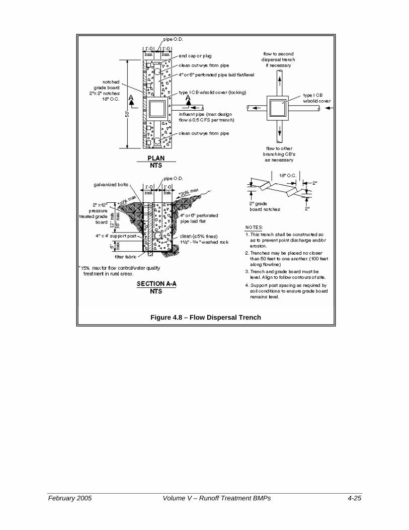
Figure 4.8 – Flow Dispersal Trench
February 2005 Volume V – Runoff Treatment BMPs 4-25
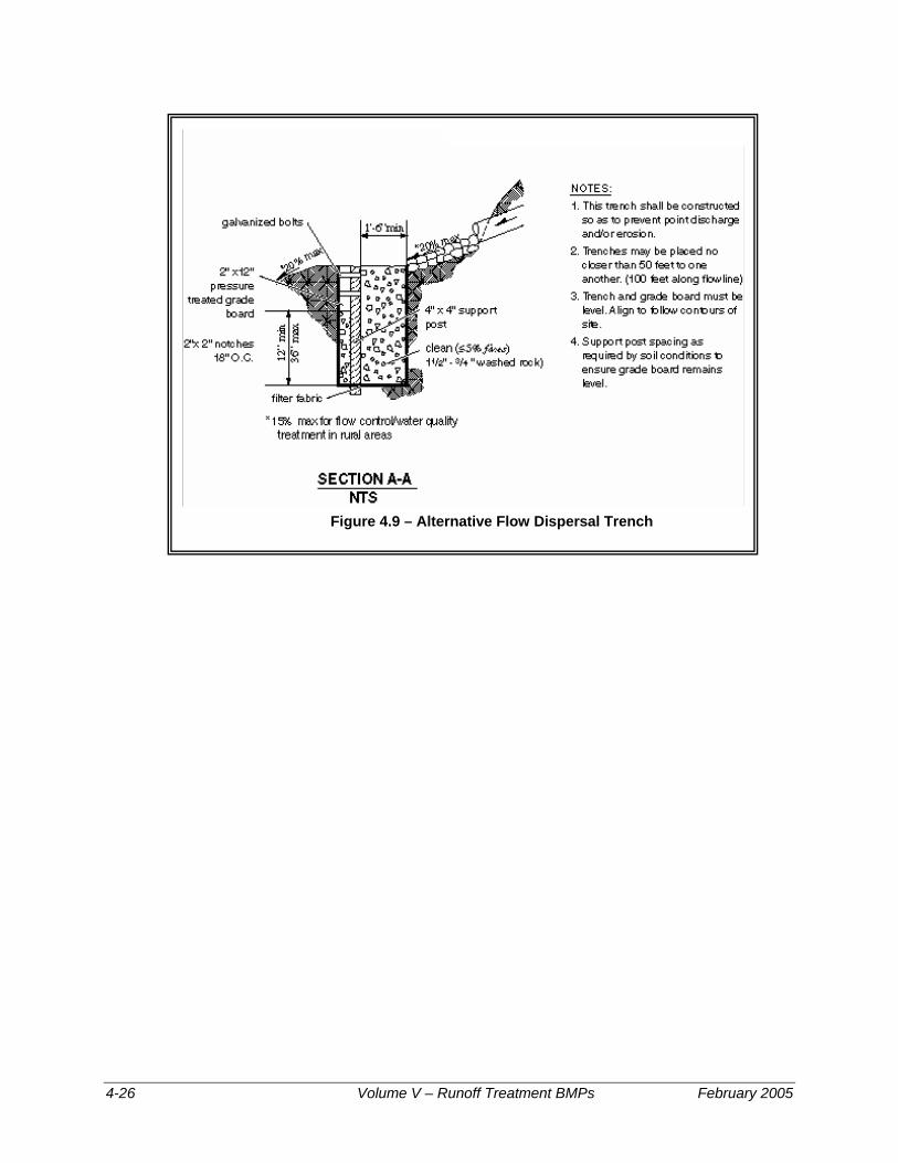
Figure 4.9 – Alternative Flow Dispersal Trench
4-26 Volume V – Runoff Treatment BMPs February 2005

Figure 4.10 – Gabion Outfall Detail
February 2005 Volume V – Runoff Treatment BMPs 4-27

Tightline Systems
• Outfall tightlines may be installed in trenches with standard bedding on slopes up to 20%. In order to minimize disturbance to slopes greater than 20%, it is recommended that tightlines be placed at grade with proper pipe anchorage and support.
• Except as indicated above, tightlines or conveyances that traverse the marine intertidal zone and connect to outfalls must be buried to a depth sufficient to avoid exposure of the line during storm events or future changes in beach elevation. If non-native material is used to bed the tightline, such material shall be covered with at least 3 feet of native bed material or equivalent.
• High density polyethylene pipe (HDPP) tightlines must be designed to address the material limitations, particularly thermal expansion and contraction and pressure design, as specified by the manufacturer. The coefficient of thermal expansion and contraction for solid wall polyethylene pipe (SWPE) is on the order of 0.001 inch per foot per Fahrenheit degree. Sliding sleeve connections must be used to address this thermal expansion and contraction. These sleeve connections consist of a section of the appropriate length of the next larger size diameter of pipe into which the outfall pipe is fitted. These sleeve connections must be located as close to the discharge end of the outfall system as is practical.
• Due to the ability of HDPP tightlines to transmit flows of very high energy, special consideration for energy dissipation must be made. Details of a sample gabion mattress energy dissipater have been provided as Figure 4.10. Flows of very high energy will require a specifically engineered energy dissipater structure.
Figure 4.11 – Diffuser TEE (an example of energy dissipating end feature)
4-28 Volume V – Runoff Treatment BMPs February 2005

energy dissipation
Figure 4.12 – Fish Habitat Improvement at New Outfalls
February 2005 Volume V – Runoff Treatment BMPs 4-29
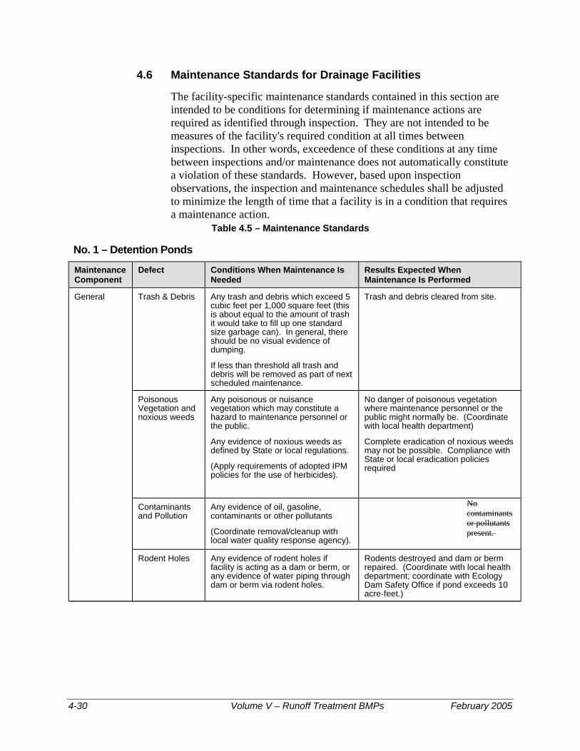
4.6 Maintenance Standards for Drainage Facilities
The facility-specific maintenance standards contained in this section are intended to be conditions for determining if maintenance actions are required as identified through inspection. They are not intended to be measures of the facility's required condition at all times between inspections. In other words, exceedence of these conditions at any time between inspections and/or maintenance does not automatically constitute a violation of these standards. However, based upon inspection observations, the inspection and maintenance schedules shall be adjusted to minimize the length of time that a facility is in a condition that requires a maintenance action.
Table 4.5 – Maintenance Standards
No. 1 – Detention Ponds
Maintenance Component
Defect Conditions When Maintenance Is Needed
Results Expected When Maintenance Is Performed
General Trash & Debris Any trash and debris which exceed 5 cubic feet per 1,000 square feet (this is about equal to the amount of trash it would take to fill up one standard size garbage can). In general, there should be no visual evidence of dumping.
If less than threshold all trash and debris will be removed as part of next scheduled maintenance.
Trash and debris cleared from site.
Poisonous Vegetation and noxious weeds
Any poisonous or nuisance vegetation which may constitute a hazard to maintenance personnel or the public.
Any evidence of noxious weeds as defined by State or local regulations.
(Apply requirements of adopted IPM policies for the use of herbicides).
No danger of poisonous vegetation where maintenance personnel or the public might normally be. (Coordinate with local health department)
Complete eradication of noxious weeds may not be possible. Compliance with State or local eradication policies required
Contaminants and Pollution
Any evidence of oil, gasoline, contaminants or other pollutants
(Coordinate removal/cleanup with local water quality response agency).
No contaminants or pollutants present.
Rodent Holes Any evidence of rodent holes if facility is acting as a dam or berm, or any evidence of water piping through dam or berm via rodent holes.
Rodents destroyed and dam or berm repaired. (Coordinate with local health department; coordinate with Ecology Dam Safety Office if pond exceeds 10 acre-feet.)
4-30 Volume V – Runoff Treatment BMPs February 2005

No. 1 – Detention Ponds
Maintenance Component
Defect Conditions When Maintenance Is Needed
Results Expected When Maintenance Is Performed
Beaver Dams Dam results in change or function of the facility.
Facility is returned to design function.
(Coordinate trapping of beavers and removal of dams with appropriate permitting agencies)
Insects When insects such as wasps and hornets interfere with maintenance activities.
Insects destroyed or removed from site.
Apply insecticides in compliance with adopted IPM policies
Tree Growth and Hazard Trees
Tree growth does not allow maintenance access or interferes with maintenance activity (i.e., slope mowing, silt removal, vactoring, or equipment movements). If trees are not interfering with access or maintenance, do not remove
If dead, diseased, or dying trees are identified
(Use a certified Arborist to determine health of tree or removal requirements)
Trees do not hinder maintenance activities. Harvested trees should be recycled into mulch or other beneficial uses (e.g., alders for firewood).
Remove hazard Trees
Side Slopes of Pond
Erosion Eroded damage over 2 inches deep where cause of damage is still present or where there is potential for continued erosion.
Any erosion observed on a compacted berm embankment.
Slopes should be stabilized using appropriate erosion control measure(s); e.g., rock reinforcement, planting of grass, compaction.
If erosion is occurring on compacted berms a licensed civil engineer should be consulted to resolve source of erosion.
Storage Area Sediment Accumulated sediment that exceeds 10% of the designed pond depth unless otherwise specified or affects inletting or outletting condition of the facility.
Sediment cleaned out to designed pond shape and depth; pond reseeded if necessary to control erosion.
Liner (If Applicable)
Liner is visible and has more than three 1/4-inch holes in it.
Liner repaired or replaced. Liner is fully covered.
February 2005 Volume V – Runoff Treatment BMPs 4-31
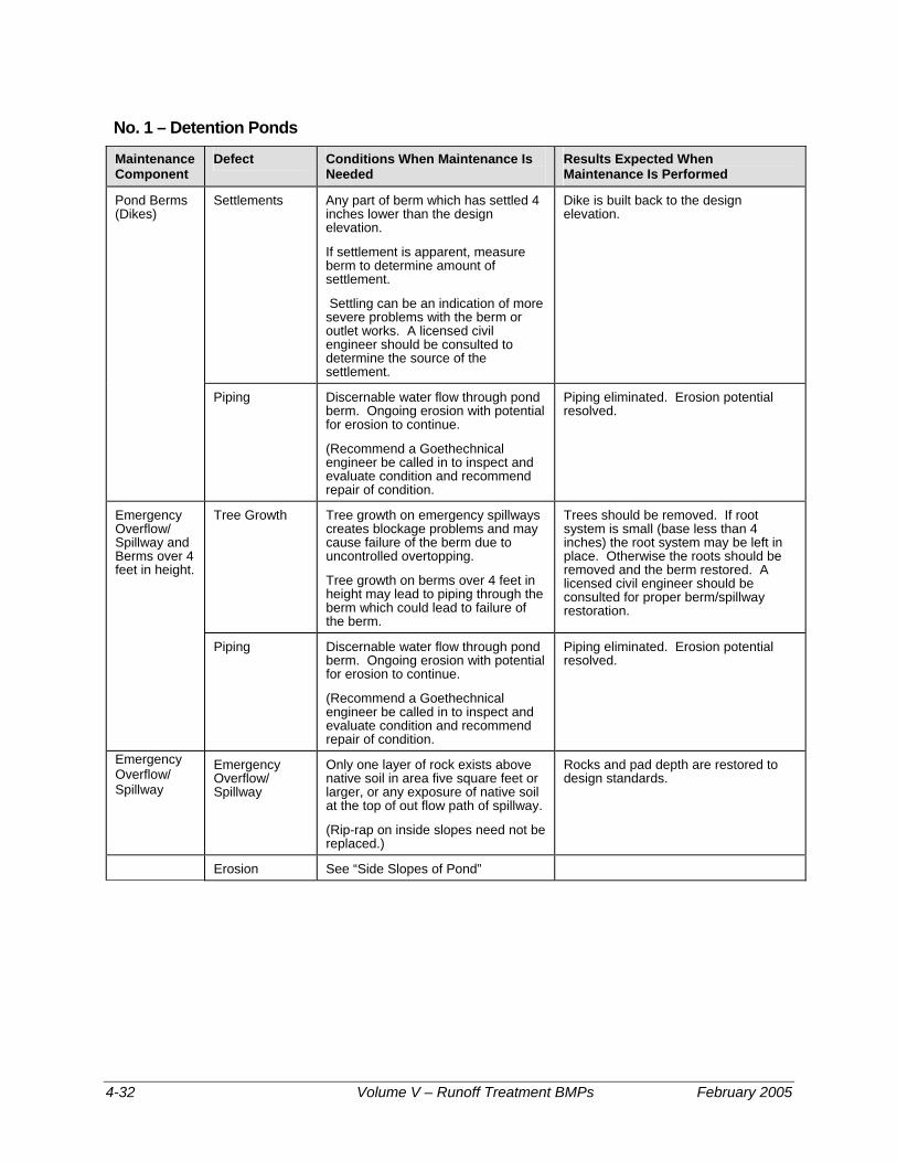
No. 1 – Detention Ponds
Maintenance Component
Defect Conditions When Maintenance Is Needed
Results Expected When Maintenance Is Performed
Pond Berms (Dikes)
Settlements Any part of berm which has settled 4 inches lower than the design elevation.
If settlement is apparent, measure berm to determine amount of settlement.
Settling can be an indication of more severe problems with the berm or outlet works. A licensed civil engineer should be consulted to determine the source of the settlement.
Dike is built back to the design elevation.
Piping Discernable water flow through pond berm. Ongoing erosion with potential for erosion to continue.
(Recommend a Goethechnical engineer be called in to inspect and evaluate condition and recommend repair of condition.
Piping eliminated. Erosion potential resolved.
Emergency Overflow/ Spillway and Berms over 4 feet in height.
Tree Growth Tree growth on emergency spillways creates blockage problems and may cause failure of the berm due to uncontrolled overtopping.
Tree growth on berms over 4 feet in height may lead to piping through the berm which could lead to failure of the berm.
Trees should be removed. If root system is small (base less than 4 inches) the root system may be left in place. Otherwise the roots should be removed and the berm restored. A licensed civil engineer should be consulted for proper berm/spillway restoration.
Piping Discernable water flow through pond berm. Ongoing erosion with potential for erosion to continue.
(Recommend a Goethechnical engineer be called in to inspect and evaluate condition and recommend repair of condition.
Piping eliminated. Erosion potential resolved.
Emergency Overflow/ Spillway
Emergency Overflow/ Spillway
Only one layer of rock exists above native soil in area five square feet or larger, or any exposure of native soil at the top of out flow path of spillway.
(Rip-rap on inside slopes need not be replaced.)
Rocks and pad depth are restored to design standards.
Erosion See “Side Slopes of Pond”
4-32 Volume V – Runoff Treatment BMPs February 2005

No. 2 – Infiltration
Maintenance Component
Defect Conditions When Maintenance Is Needed
Results Expected When Maintenance Is Performed
General Trash & Debris See "Detention Ponds" (No. 1). See "Detention Ponds" (No. 1).
Poisonous/Noxious Vegetation
See "Detention Ponds" (No. 1). See "Detention Ponds" (No. 1).
Contaminants and Pollution
See "Detention Ponds" (No. 1). See "Detention Ponds" (No. 1).
Rodent Holes See "Detention Ponds" (No. 1). See "Detention Ponds" (No. 1)
Storage Area Sediment Water ponding in infiltration pond after rainfall ceases and appropriate time allowed for infiltration.
(A percolation test pit or test of facility indicates facility is only working at 90% of its designed capabilities. If two inches or more sediment is present, remove).
Sediment is removed and/or facility is cleaned so that infiltration system works according to design.
Filter Bags (if applicable)
Filled with Sediment and Debris
Sediment and debris fill bag more than 1/2 full.
Filter bag is replaced or system is redesigned.
Rock Filters Sediment and Debris
By visual inspection, little or no water flows through filter during heavy rain storms.
Gravel in rock filter is replaced.
Side Slopes of Pond
Erosion See "Detention Ponds" (No. 1). See "Detention Ponds" (No. 1).
Emergency Overflow Spillway and Berms over 4 feet in height.
Tree Growth See "Detention Ponds" (No. 1). See "Detention Ponds" (No. 1).
Piping See "Detention Ponds" (No. 1). See "Detention Ponds" (No. 1).
Emergency Overflow Spillway
Rock Missing See "Detention Ponds" (No. 1). See "Detention Ponds" (No. 1).
Erosion See "Detention Ponds" (No. 1). See "Detention Ponds" (No. 1).
Pre-settling Ponds and Vaults
Facility or sump filled with Sediment and/or debris
6" or designed sediment trap depth of sediment.
Sediment is removed.
February 2005 Volume V – Runoff Treatment BMPs 4-33

No. 3 – Closed Detention Systems (Tanks/Vaults) Maintenance Component
Defect Conditions When Maintenance is Needed Results Expected When Maintenance is Performed
Storage Area Plugged Air Vents One-half of the cross section of a vent is blocked at any point or the vent is damaged.
Vents open and functioning.
Debris and Sediment Accumulated sediment depth exceeds 10% of the diameter of the storage area for 1/2 length of storage vault or any point depth exceeds 15% of diameter.
(Example: 72-inch storage tank would require cleaning when sediment reaches depth of 7 inches for more than 1/2 length of tank.)
All sediment and debris removed from storage area.
Joints Between Tank/Pipe Section
Any openings or voids allowing material to be transported into facility.
(Will require engineering analysis to determine structural stability).
All joint between tank/pipe sections are sealed.
Tank Pipe Bent Out of Shape
Any part of tank/pipe is bent out of shape more than 10% of its design shape. (Review required by engineer to determine structural stability).
Tank/pipe repaired or replaced to design.
Vault Structure Includes Cracks in Wall, Bottom, Damage to Frame and/or Top Slab
Cracks wider than 1/2-inch and any evidence of soil particles entering the structure through the cracks, or maintenance/inspection personnel determines that the vault is not structurally sound.
Vault replaced or repaired to design specifications and is structurally sound.
Cracks wider than 1/2-inch at the joint of any inlet/outlet pipe or any evidence of soil particles entering the vault through the walls.
No cracks more than 1/4-inch wide at the joint of the inlet/outlet pipe.
Manhole Cover Not in Place Cover is missing or only partially in place. Any open manhole requires maintenance.
Manhole is closed.
Locking Mechanism Not Working
Mechanism cannot be opened by one maintenance person with proper tools. Bolts into frame have less than 1/2 inch of thread (may not apply to self-locking lids).
Mechanism opens with proper tools.
Cover Difficult to Remove
One maintenance person cannot remove lid after applying normal lifting pressure. Intent is to keep cover from sealing off access to maintenance.
Cover can be removed and reinstalled by one maintenance person.
Ladder Rungs Unsafe Ladder is unsafe due to missing rungs, misalignment, not securely attached to structure wall, rust, or cracks.
Ladder meets design standards. Allows maintenance person safe access.
Catch Basins See “Catch Basins” (No. 5)
See “Catch Basins” (No. 5). See “Catch Basins” (No. 5).
4-34 Volume V – Runoff Treatment BMPs February 2005

No. 4 – Control Structure/Flow Restrictor Maintenance Component
Defect Condition When Maintenance is Needed Results Expected When Maintenance is Performed
General Trash and Debris (Includes Sediment)
Material exceeds 25% of sump depth or 1 foot below orifice plate.
Control structure orifice is not blocked. All trash and debris removed.
Structural Damage Structure is not securely attached to manhole wall.
Structure securely attached to wall and outlet pipe.
Structure is not in upright position (allow up to 10% from plumb).
Structure in correct position.
Connections to outlet pipe are not watertight and show signs of rust.
Connections to outlet pipe are water tight; structure repaired or replaced and works as designed.
Any holes--other than designed holes--in the structure.
Structure has no holes other than designed holes.
Cleanout Gate Damaged or Missing Cleanout gate is not watertight or is missing. Gate is watertight and works as designed.
Gate cannot be moved up and down by one maintenance person.
Gate moves up and down easily and is watertight.
Chain/rod leading to gate is missing or damaged.
Chain is in place and works as designed.
Gate is rusted over 50% of its surface area. Gate is repaired or replaced to meet design standards.
Orifice Plate Damaged or Missing Control device is not working properly due to missing, out of place, or bent orifice plate.
Plate is in place and works as designed.
Obstructions Any trash, debris, sediment, or vegetation blocking the plate.
Plate is free of all obstructions and works as designed.
Overflow Pipe Obstructions Any trash or debris blocking (or having the potential of blocking) the overflow pipe.
Pipe is free of all obstructions and works as designed.
Manhole See “Closed Detention Systems” (No. 3).
See “Closed Detention Systems” (No. 3). See “Closed Detention Systems” (No. 3).
Catch Basin See “Catch Basins” (No. 5).
See “Catch Basins” (No. 5). See “Catch Basins” (No. 5).
February 2005 Volume V – Runoff Treatment BMPs 4-35

No. 5 – Catch Basins
Maintenance Component
Defect Conditions When Maintenance is Needed Results Expected When Maintenance is performed
General Trash & Debris
Trash or debris which is located immediately in front of the catch basin opening or is blocking inletting capacity of the basin by more than 10%.
No Trash or debris located immediately in front of catch basin or on grate opening.
Trash or debris (in the basin) that exceeds 60 percent of the sump depth as measured from the bottom of basin to invert of the lowest pipe into or out of the basin, but in no case less than a minimum of six inches clearance from the debris surface to the invert of the lowest pipe.
No trash or debris in the catch basin.
Trash or debris in any inlet or outlet pipe blocking more than 1/3 of its height.
Inlet and outlet pipes free of trash or debris.
Dead animals or vegetation that could generate odors that could cause complaints or dangerous gases (e.g., methane).
No dead animals or vegetation present within the catch basin.
Sediment Sediment (in the basin) that exceeds 60 percent of the sump depth as measured from the bottom of basin to invert of the lowest pipe into or out of the basin, but in no case less than a minimum of 6 inches clearance from the sediment surface to the invert of the lowest pipe.
No sediment in the catch basin
Structure Damage to Frame and/or Top Slab
Top slab has holes larger than 2 square inches or cracks wider than 1/4 inch
(Intent is to make sure no material is running into basin).
Top slab is free of holes and cracks.
Frame not sitting flush on top slab, i.e., separation of more than 3/4 inch of the frame from the top slab. Frame not securely attached
Frame is sitting flush on the riser rings or top slab and firmly attached.
Fractures or Cracks in Basin Walls/ Bottom
Maintenance person judges that structure is unsound.
Basin replaced or repaired to design standards.
Grout fillet has separated or cracked wider than 1/2 inch and longer than 1 foot at the joint of any inlet/outlet pipe or any evidence of soil particles entering catch basin through cracks.
Pipe is regrouted and secure at basin wall.
Settlement/ Misalignment
If failure of basin has created a safety, function, or design problem.
Basin replaced or repaired to design standards.
Vegetation Vegetation growing across and blocking more than 10% of the basin opening.
No vegetation blocking opening to basin.
Vegetation growing in inlet/outlet pipe joints that is more than six inches tall and less than six inches apart.
No vegetation or root growth present.
4-36 Volume V – Runoff Treatment BMPs February 2005
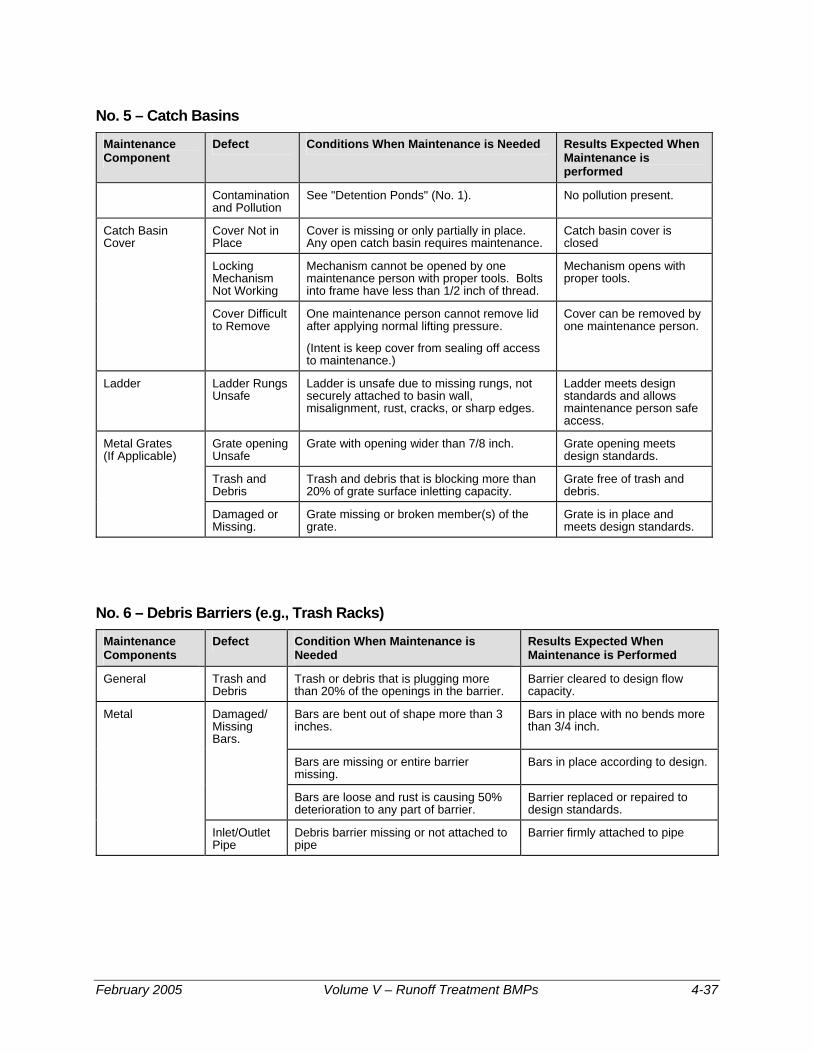
No. 5 – Catch Basins
Maintenance Component
Defect Conditions When Maintenance is Needed Results Expected When Maintenance is performed
Contamination and Pollution
See "Detention Ponds" (No. 1). No pollution present.
Catch Basin Cover
Cover Not in Place
Cover is missing or only partially in place. Any open catch basin requires maintenance.
Catch basin cover is closed
Locking Mechanism Not Working
Mechanism cannot be opened by one maintenance person with proper tools. Bolts into frame have less than 1/2 inch of thread.
Mechanism opens with proper tools.
Cover Difficult to Remove
One maintenance person cannot remove lid after applying normal lifting pressure.
(Intent is keep cover from sealing off access to maintenance.)
Cover can be removed by one maintenance person.
Ladder Ladder Rungs Unsafe
Ladder is unsafe due to missing rungs, not securely attached to basin wall, misalignment, rust, cracks, or sharp edges.
Ladder meets design standards and allows maintenance person safe access.
Metal Grates (If Applicable)
Grate opening Unsafe
Grate with opening wider than 7/8 inch. Grate opening meets design standards.
Trash and Debris
Trash and debris that is blocking more than 20% of grate surface inletting capacity.
Grate free of trash and debris.
Damaged or Missing.
Grate missing or broken member(s) of the grate.
Grate is in place and meets design standards.
No. 6 – Debris Barriers (e.g., Trash Racks) Maintenance Components
Defect Condition When Maintenance is Needed
Results Expected When Maintenance is Performed
General Trash and Debris
Trash or debris that is plugging more than 20% of the openings in the barrier.
Barrier cleared to design flow capacity.
Metal Damaged/ Missing Bars.
Bars are bent out of shape more than 3 inches.
Bars in place with no bends more than 3/4 inch.
Bars are missing or entire barrier missing.
Bars in place according to design.
Bars are loose and rust is causing 50% deterioration to any part of barrier.
Barrier replaced or repaired to design standards.
Inlet/Outlet Pipe
Debris barrier missing or not attached to pipe
Barrier firmly attached to pipe
February 2005 Volume V – Runoff Treatment BMPs 4-37
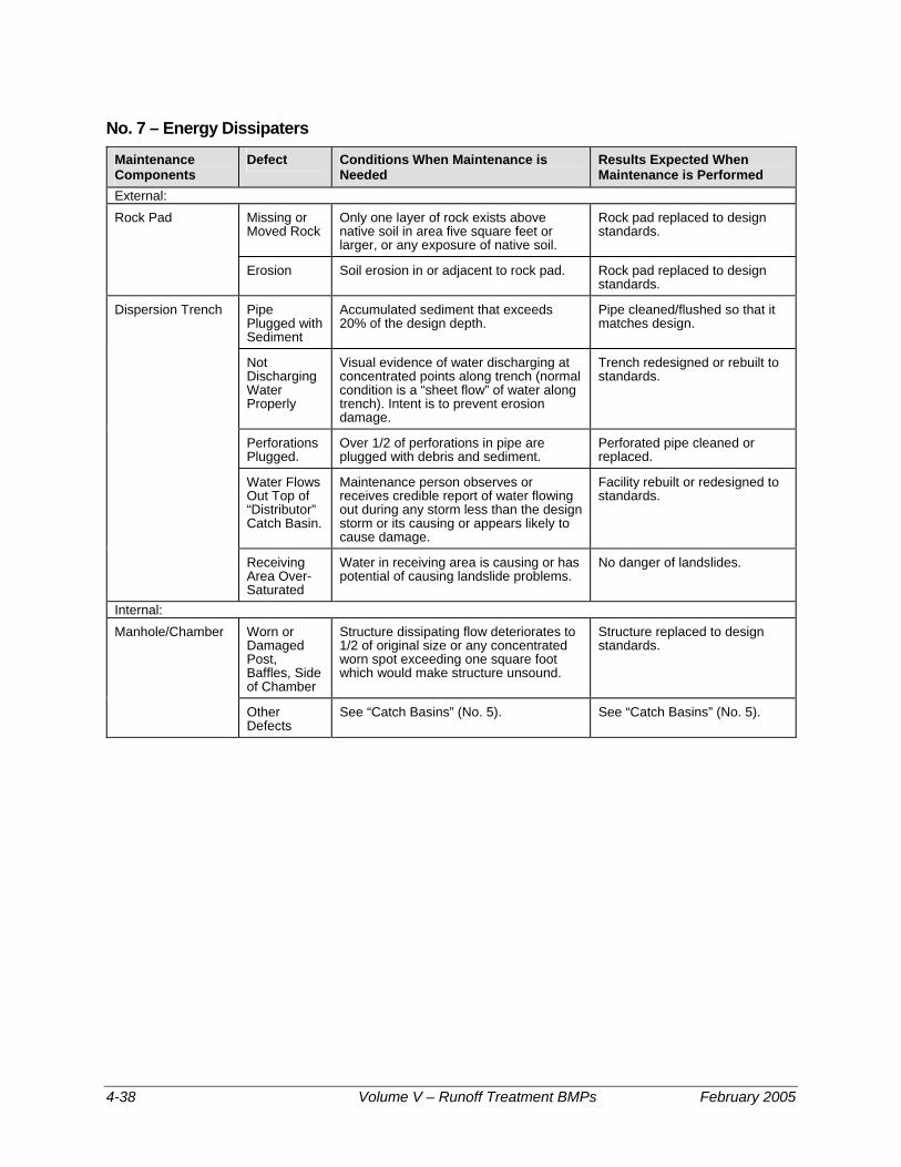
No. 7 – Energy Dissipaters Maintenance Components
Defect Conditions When Maintenance is Needed
Results Expected When Maintenance is Performed
External: Rock Pad Missing or
Moved Rock Only one layer of rock exists above native soil in area five square feet or larger, or any exposure of native soil.
Rock pad replaced to design standards.
Erosion Soil erosion in or adjacent to rock pad. Rock pad replaced to design standards.
Dispersion Trench Pipe Plugged with Sediment
Accumulated sediment that exceeds 20% of the design depth.
Pipe cleaned/flushed so that it matches design.
Not Discharging Water Properly
Visual evidence of water discharging at concentrated points along trench (normal condition is a “sheet flow” of water along trench). Intent is to prevent erosion damage.
Trench redesigned or rebuilt to standards.
Perforations Plugged.
Over 1/2 of perforations in pipe are plugged with debris and sediment.
Perforated pipe cleaned or replaced.
Water Flows Out Top of “Distributor” Catch Basin.
Maintenance person observes or receives credible report of water flowing out during any storm less than the design storm or its causing or appears likely to cause damage.
Facility rebuilt or redesigned to standards.
Receiving Area Over-Saturated
Water in receiving area is causing or has potential of causing landslide problems.
No danger of landslides.
Internal: Manhole/Chamber Worn or
Damaged Post, Baffles, Side of Chamber
Structure dissipating flow deteriorates to 1/2 of original size or any concentrated worn spot exceeding one square foot which would make structure unsound.
Structure replaced to design standards.
Other Defects
See “Catch Basins” (No. 5). See “Catch Basins” (No. 5).
4-38 Volume V – Runoff Treatment BMPs February 2005
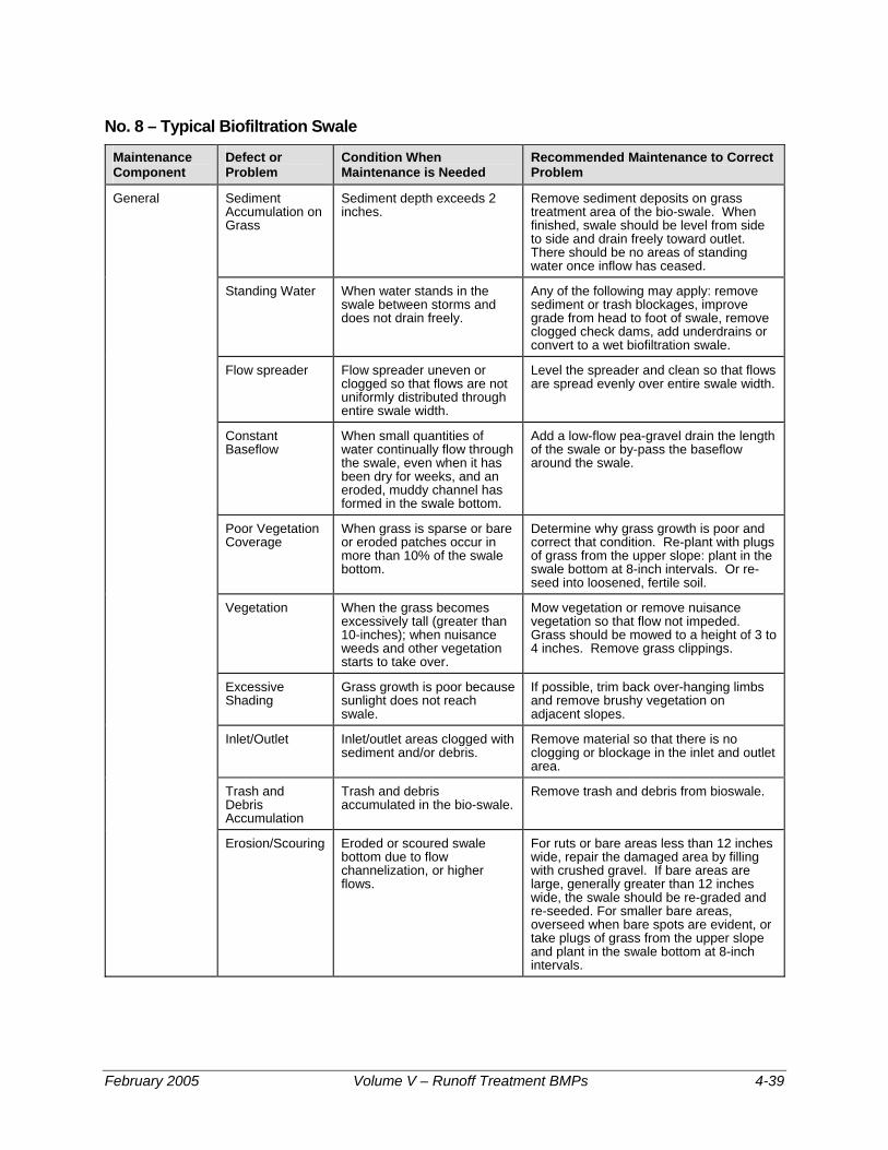
No. 8 – Typical Biofiltration Swale
Maintenance Component
Defect or Problem
Condition When Maintenance is Needed
Recommended Maintenance to Correct Problem
General Sediment Accumulation on Grass
Sediment depth exceeds 2 inches.
Remove sediment deposits on grass treatment area of the bio-swale. When finished, swale should be level from side to side and drain freely toward outlet. There should be no areas of standing water once inflow has ceased.
Standing Water When water stands in the swale between storms and does not drain freely.
Any of the following may apply: remove sediment or trash blockages, improve grade from head to foot of swale, remove clogged check dams, add underdrains or convert to a wet biofiltration swale.
Flow spreader Flow spreader uneven or clogged so that flows are not uniformly distributed through entire swale width.
Level the spreader and clean so that flows are spread evenly over entire swale width.
Constant Baseflow
When small quantities of water continually flow through the swale, even when it has been dry for weeks, and an eroded, muddy channel has formed in the swale bottom.
Add a low-flow pea-gravel drain the length of the swale or by-pass the baseflow around the swale.
Poor Vegetation Coverage
When grass is sparse or bare or eroded patches occur in more than 10% of the swale bottom.
Determine why grass growth is poor and correct that condition. Re-plant with plugs of grass from the upper slope: plant in the swale bottom at 8-inch intervals. Or re-seed into loosened, fertile soil.
Vegetation When the grass becomes excessively tall (greater than 10-inches); when nuisance weeds and other vegetation starts to take over.
Mow vegetation or remove nuisance vegetation so that flow not impeded. Grass should be mowed to a height of 3 to 4 inches. Remove grass clippings.
Excessive Shading
Grass growth is poor because sunlight does not reach swale.
If possible, trim back over-hanging limbs and remove brushy vegetation on adjacent slopes.
Inlet/Outlet Inlet/outlet areas clogged with sediment and/or debris.
Remove material so that there is no clogging or blockage in the inlet and outlet area.
Trash and Debris Accumulation
Trash and debris accumulated in the bio-swale.
Remove trash and debris from bioswale.
Erosion/Scouring Eroded or scoured swale bottom due to flow channelization, or higher flows.
For ruts or bare areas less than 12 inches wide, repair the damaged area by filling with crushed gravel. If bare areas are large, generally greater than 12 inches wide, the swale should be re-graded and re-seeded. For smaller bare areas, overseed when bare spots are evident, or take plugs of grass from the upper slope and plant in the swale bottom at 8-inch intervals.
February 2005 Volume V – Runoff Treatment BMPs 4-39

No. 9 – Wet Biofiltration Swale
Maintenance Component
Defect or Problem
Condition When Maintenance is Needed
Recommended Maintenance to Correct Problem
General Sediment Accumulation
Sediment depth exceeds 2-inches in 10% of the swale treatment area.
Remove sediment deposits in treatment area.
Water Depth
Water not retained to a depth of about 4 inches during the wet season.
Build up or repair outlet berm so that water is retained in the wet swale.
Wetland Vegetation
Vegetation becomes sparse and does not provide adequate filtration, OR vegetation is crowded out by very dense clumps of cattail, which do not allow water to flow through the clumps.
Determine cause of lack of vigor of vegetation and correct. Replant as needed. For excessive cattail growth, cut cattail shoots back and compost off-site. Note: normally wetland vegetation does not need to be harvested unless die-back is causing oxygen depletion in downstream waters.
Inlet/Outlet Inlet/outlet area clogged with sediment and/or debris.
Remove clogging or blockage in the inlet and outlet areas.
Trash and Debris Accumulation
See "Detention Ponds" (No. 1). Remove trash and debris from wet swale.
Erosion/Scouring Swale has eroded or scoured due to flow channelization, or higher flows.
Check design flows to assure swale is large enough to handle flows. By-pass excess flows or enlarge swale. Replant eroded areas with fibrous-rooted plants such as Juncus effusus (soft rush) in wet areas or snowberry (Symphoricarpos albus) in dryer areas.
4-40 Volume V – Runoff Treatment BMPs February 2005

No. 10 – Filter Strips
Maintenance Component
Defect or Problem
Condition When Maintenance is Needed
Recommended Maintenance to Correct Problem
General Sediment Accumulation on Grass
Sediment depth exceeds 2 inches.
Remove sediment deposits, re-level so slope is even and flows pass evenly through strip.
Vegetation When the grass becomes excessively tall (greater than 10-inches); when nuisance weeds and other vegetation starts to take over.
Mow grass, control nuisance vegetation, such that flow not impeded. Grass should be mowed to a height between 3-4 inches.
Trash and Debris Accumulation
Trash and debris accumulated on the filter strip.
Remove trash and Debris from filter.
Erosion/Scouring Eroded or scoured areas due to flow channelization, or higher flows.
For ruts or bare areas less than 12 inches wide, repair the damaged area by filling with crushed gravel. The grass will creep in over the rock in time. If bare areas are large, generally greater than 12 inches wide, the filter strip should be re-graded and re-seeded. For smaller bare areas, overseed when bare spots are evident.
Flow spreader Flow spreader uneven or clogged so that flows are not uniformly distributed through entire filter width.
Level the spreader and clean so that flows are spread evenly over entire filter width.
February 2005 Volume V – Runoff Treatment BMPs 4-41

No. 11 – Wetponds
Maintenance Component
Defect Condition When Maintenance is Needed
Results Expected When Maintenance is Performed
General Water level
First cell is empty, doesn't hold water.
Line the first cell to maintain at least 4 feet of water. Although the second cell may drain, the first cell must remain full to control turbulence of the incoming flow and reduce sediment resuspension.
Trash and Debris
Accumulation that exceeds 1 CF per 1000-SF of pond area.
Trash and debris removed from pond.
Inlet/Outlet Pipe
Inlet/Outlet pipe clogged with sediment and/or debris material.
No clogging or blockage in the inlet and outlet piping.
Sediment Accumulation in Pond Bottom
Sediment accumulations in pond bottom that exceeds the depth of sediment zone plus 6-inches, usually in the first cell.
Sediment removed from pond bottom.
Oil Sheen on Water
Prevalent and visible oil sheen. Oil removed from water using oil-absorbent pads or vactor truck. Source of oil located and corrected. If chronic low levels of oil persist, plant wetland plants such as Juncus effusus (soft rush) which can uptake small concentrations of oil.
Erosion Erosion of the pond’s side slopes and/or scouring of the pond bottom, that exceeds 6-inches, or where continued erosion is prevalent.
Slopes stabilized using proper erosion control measures and repair methods.
Settlement of Pond Dike/Berm
Any part of these components that has settled 4-inches or lower than the design elevation, or inspector determines dike/berm is unsound.
Dike/berm is repaired to specifications.
Internal Berm Berm dividing cells should be level.
Berm surface is leveled so that water flows evenly over entire length of berm.
Overflow Spillway
Rock is missing and soil is exposed at top of spillway or outside slope.
Rocks replaced to specifications.
4-42 Volume V – Runoff Treatment BMPs February 2005

No. 12 – Wetvaults
Maintenance Component
Defect Condition When Maintenance is Needed
Results Expected When Maintenance is Performed
General Trash/Debris Accumulation
Trash and debris accumulated in vault, pipe or inlet/outlet (includes floatables and non-floatables).
Remove trash and debris from vault.
Sediment Accumulation in Vault
Sediment accumulation in vault bottom exceeds the depth of the sediment zone plus 6-inches.
Remove sediment from vault.
Damaged Pipes Inlet/outlet piping damaged or broken and in need of repair.
Pipe repaired and/or replaced.
Access Cover Damaged/Not Working
Cover cannot be opened or removed, especially by one person.
Pipe repaired or replaced to proper working specifications.
Ventilation Ventilation area blocked or plugged.
Blocking material removed or cleared from ventilation area. A specified % of the vault surface area must provide ventilation to the vault interior (see design specifications).
Vault Structure Damage - Includes Cracks in Walls Bottom, Damage to Frame and/or Top Slab
Maintenance/inspection personnel determine that the vault is not structurally sound.
Vault replaced or repairs made so that vault meets design specifications and is structurally sound.
Cracks wider than 1/2-inch at the joint of any inlet/outlet pipe or evidence of soil particles entering through the cracks.
Vault repaired so that no cracks exist wider than 1/4-inch at the joint of the inlet/outlet pipe.
Baffles Baffles corroding, cracking, warping and/or showing signs of failure as determined by maintenance/inspection staff.
Baffles repaired or replaced to specifications.
Access Ladder Damage
Ladder is corroded or deteriorated, not functioning properly, not attached to structure wall, missing rungs, has cracks and/or misaligned. Confined space warning sign missing.
Ladder replaced or repaired to specifications, and is safe to use as determined by inspection personnel. Replace sign warning of confined space entry requirements. Ladder and entry notification complies with OSHA standards.
February 2005 Volume V – Runoff Treatment BMPs 4-43

No. 13 – Sand Filters (above ground/open)
Maintenance Component
Defect Condition When Maintenance is Needed
Results Expected When Maintenance is Performed
Above Ground (open sand filter)
Sediment Accumulation on top layer
Sediment depth exceeds 1/2-inch. No sediment deposit on grass layer of sand filter that would impede permeability of the filter section.
Trash and Debris Accumulations
Trash and debris accumulated on sand filter bed.
Trash and debris removed from sand filter bed.
Sediment/ Debris in Clean-Outs
When the clean-outs become full or partially plugged with sediment and/or debris.
Sediment removed from clean-outs.
Sand Filter Media
Drawdown of water through the sand filter media takes longer than 24-hours, and/or flow through the overflow pipes occurs frequently.
Top several inches of sand are scraped. May require replacement of entire sand filter depth depending on extent of plugging (a sieve analysis is helpful to determine if the lower sand has too high a proportion of fine material).
Prolonged Flows
Sand is saturated for prolonged periods of time (several weeks) and does not dry out between storms due to continuous base flow or prolonged flows from detention facilities.
Low, continuous flows are limited to a small portion of the facility by using a low wooden divider or slightly depressed sand surface.
Short Circuiting
When flows become concentrated over one section of the sand filter rather than dispersed.
Flow and percolation of water through sand filter is uniform and dispersed across the entire filter area.
Erosion Damage to Slopes
Erosion over 2-inches deep where cause of damage is prevalent or potential for continued erosion is evident.
Slopes stabilized using proper erosion control measures.
Rock Pad Missing or Out of Place
Soil beneath the rock is visible. Rock pad replaced or rebuilt to design specifications.
Flow Spreader Flow spreader uneven or clogged so that flows are not uniformly distributed across sand filter.
Spreader leveled and cleaned so that flows are spread evenly over sand filter.
Damaged Pipes
Any part of the piping that is crushed or deformed more than 20% or any other failure to the piping.
Pipe repaired or replaced.
4-44 Volume V – Runoff Treatment BMPs February 2005
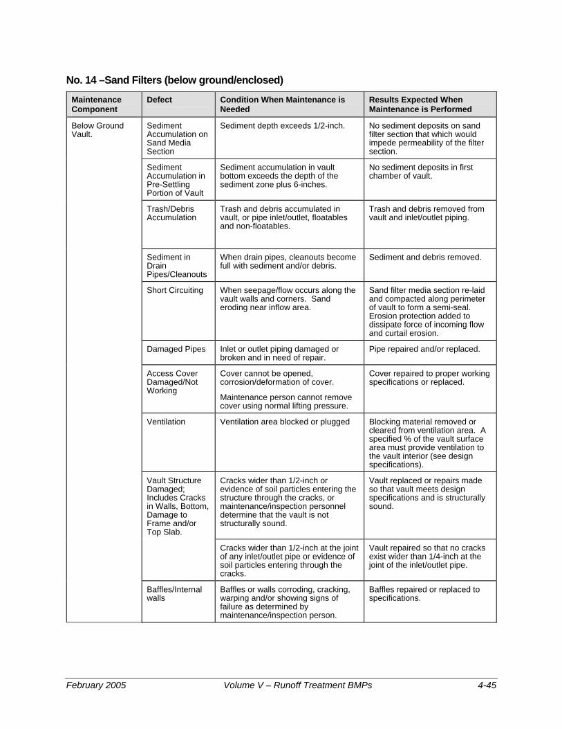
No. 14 –Sand Filters (below ground/enclosed)
Maintenance Component
Defect Condition When Maintenance is Needed
Results Expected When Maintenance is Performed
Below Ground Vault.
Sediment Accumulation on Sand Media Section
Sediment depth exceeds 1/2-inch. No sediment deposits on sand filter section that which would impede permeability of the filter section.
Sediment Accumulation in Pre-Settling Portion of Vault
Sediment accumulation in vault bottom exceeds the depth of the sediment zone plus 6-inches.
No sediment deposits in first chamber of vault.
Trash/Debris Accumulation
Trash and debris accumulated in vault, or pipe inlet/outlet, floatables and non-floatables.
Trash and debris removed from vault and inlet/outlet piping.
Sediment in Drain Pipes/Cleanouts
When drain pipes, cleanouts become full with sediment and/or debris.
Sediment and debris removed.
Short Circuiting When seepage/flow occurs along the vault walls and corners. Sand eroding near inflow area.
Sand filter media section re-laid and compacted along perimeter of vault to form a semi-seal. Erosion protection added to dissipate force of incoming flow and curtail erosion.
Damaged Pipes Inlet or outlet piping damaged or broken and in need of repair.
Pipe repaired and/or replaced.
Access Cover Damaged/Not Working
Cover cannot be opened, corrosion/deformation of cover.
Maintenance person cannot remove cover using normal lifting pressure.
Cover repaired to proper working specifications or replaced.
Ventilation Ventilation area blocked or plugged Blocking material removed or cleared from ventilation area. A specified % of the vault surface area must provide ventilation to the vault interior (see design specifications).
Vault Structure Damaged; Includes Cracks in Walls, Bottom, Damage to Frame and/or Top Slab.
Cracks wider than 1/2-inch or evidence of soil particles entering the structure through the cracks, or maintenance/inspection personnel determine that the vault is not structurally sound.
Vault replaced or repairs made so that vault meets design specifications and is structurally sound.
Cracks wider than 1/2-inch at the joint of any inlet/outlet pipe or evidence of soil particles entering through the cracks.
Vault repaired so that no cracks exist wider than 1/4-inch at the joint of the inlet/outlet pipe.
Baffles/Internal walls
Baffles or walls corroding, cracking, warping and/or showing signs of failure as determined by maintenance/inspection person.
Baffles repaired or replaced to specifications.
February 2005 Volume V – Runoff Treatment BMPs 4-45

No. 14 –Sand Filters (below ground/enclosed)
Maintenance Component
Defect Condition When Maintenance is Needed
Results Expected When Maintenance is Performed
Access Ladder Damaged
Ladder is corroded or deteriorated, not functioning properly, not securely attached to structure wall, missing rungs, cracks, and misaligned.
Ladder replaced or repaired to specifications, and is safe to use as determined by inspection personnel.
4-46 Volume V – Runoff Treatment BMPs February 2005

No. 15 – Stormfilter™ (leaf compost filter)
Maintenance Component
Defect Condition When Maintenance is Needed
Results Expected When Maintenance is Performed
Below Ground Vault
Sediment Accumulation on Media.
Sediment depth exceeds 0.25-inches. No sediment deposits which would impede permeability of the compost media.
Sediment Accumulation in Vault
Sediment depth exceeds 6-inches in first chamber.
No sediment deposits in vault bottom of first chamber.
Trash/Debris Accumulation
Trash and debris accumulated on compost filter bed.
Trash and debris removed from the compost filter bed.
Sediment in Drain Pipes/Clean-Outs
When drain pipes, clean-outs, become full with sediment and/or debris.
Sediment and debris removed.
Damaged Pipes Any part of the pipes that are crushed or damaged due to corrosion and/or settlement.
Pipe repaired and/or replaced.
Access Cover Damaged/Not Working
Cover cannot be opened; one person cannot open the cover using normal lifting pressure, corrosion/deformation of cover.
Cover repaired to proper working specifications or replaced.
Vault Structure Includes Cracks in Wall, Bottom, Damage to Frame and/or Top Slab
Cracks wider than 1/2-inch or evidence of soil particles entering the structure through the cracks, or maintenance/inspection personnel determine that the vault is not structurally sound.
Vault replaced or repairs made so that vault meets design specifications and is structurally sound.
Cracks wider than 1/2-inch at the joint of any inlet/outlet pipe or evidence of soil particles entering through the cracks.
Vault repaired so that no cracks exist wider than 1/4-inch at the joint of the inlet/outlet pipe.
Baffles Baffles corroding, cracking warping, and/or showing signs of failure as determined by maintenance/inspection person.
Baffles repaired or replaced to specifications.
Access Ladder Damaged
Ladder is corroded or deteriorated, not functioning properly, not securely attached to structure wall, missing rungs, cracks, and misaligned.
Ladder replaced or repaired and meets specifications, and is safe to use as determined by inspection personnel.
Below Ground Cartridge Type
Compost Media Drawdown of water through the media takes longer than 1 hour, and/or overflow occurs frequently.
Media cartridges replaced.
Short Circuiting Flows do not properly enter filter cartridges.
Filter cartridges replaced.
February 2005 Volume V – Runoff Treatment BMPs 4-47

No. 16 – Baffle Oil/Water Separators (API Type)
Maintenance Component
Defect Condition When Maintenance is Needed
Results Expected When Maintenance is Performed
Effluent discharge from vault should be clear with out thick visible sheen.
General Monitoring Inspection of discharge water for obvious signs of poor water quality.
Sediment Accumulation
Sediment depth in bottom of vault exceeds 6-inches in depth.
No sediment deposits on vault bottom that would impede flow through the vault and reduce separation efficiency.
Trash and Debris Accumulation
Trash and debris accumulation in vault, or pipe inlet/outlet, floatables and non-floatables.
Trash and debris removed from vault, and inlet/outlet piping.
Oil Accumulation Oil accumulations that exceed 1-inch, at the surface of the water.
Extract oil from vault by vactoring. Disposal in accordance with state and local rules and regulations.
Damaged Pipes Inlet or outlet piping damaged or broken and in need of repair.
Pipe repaired or replaced.
Access Cover Damaged/Not Working
Cover cannot be opened, corrosion/deformation of cover.
Cover repaired to proper working specifications or replaced.
Vault Structure Damage - Includes Cracks in Walls Bottom, Damage to Frame and/or Top Slab
See “Catch Basins” (No. 5)
Vault replaced or repairs made so that vault meets design specifications and is structurally sound.
Cracks wider than 1/2-inch at the joint of any inlet/outlet pipe or evidence of soil particles entering through the cracks.
Vault repaired so that no cracks exist wider than 1/4-inch at the joint of the inlet/outlet pipe.
Baffles Baffles corroding, cracking, warping and/or showing signs of failure as determined by maintenance/inspection person.
Baffles repaired or replaced to specifications.
Access Ladder Damaged
Ladder is corroded or deteriorated, not functioning properly, not securely attached to structure wall, missing rungs, cracks, and misaligned.
Ladder replaced or repaired and meets specifications, and is safe to use as determined by inspection personnel.
4-48 Volume V – Runoff Treatment BMPs February 2005

No. 17 – Coalescing Plate Oil/Water Separators
Maintenance Component
Defect Condition When Maintenance is Needed
Results Expected When Maintenance is Performed
General Monitoring Inspection of discharge water for obvious signs of poor water quality.
Effluent discharge from vault should be clear with no thick visible sheen.
Sediment Accumulation
Sediment depth in bottom of vault exceeds 6-inches in depth and/or visible signs of sediment on plates.
No sediment deposits on vault bottom and plate media, which would impede flow through the vault and reduce separation efficiency.
Trash and Debris Accumulation
Trash and debris accumulated in vault, or pipe inlet/outlet, floatables and non-floatables.
Trash and debris removed from vault, and inlet/outlet piping.
Oil Accumulation Oil accumulation that exceeds 1-inch at the water surface.
Oil is extracted from vault using vactoring methods. Coalescing plates are cleaned by thoroughly rinsing and flushing. Should be no visible oil depth on water.
Damaged Coalescing Plates
Plate media broken, deformed, cracked and/or showing signs of failure.
A portion of the media pack or the entire plate pack is replaced depending on severity of failure.
Damaged Pipes Inlet or outlet piping damaged or broken and in need of repair.
Pipe repaired and or replaced.
Baffles Baffles corroding, cracking, warping and/or showing signs of failure as determined by maintenance/inspection person.
Baffles repaired or replaced to specifications.
Vault Structure Damage - Includes Cracks in Walls, Bottom, Damage to Frame and/or Top Slab
Cracks wider than 1/2-inch or evidence of soil particles entering the structure through the cracks, or maintenance/inspection personnel determine that the vault is not structurally sound.
Vault replaced or repairs made so that vault meets design specifications and is structurally sound.
Cracks wider than 1/2-inch at the joint of any inlet/outlet pipe or evidence of soil particles entering through the cracks.
Vault repaired so that no cracks exist wider than 1/4-inch at the joint of the inlet/outlet pipe.
Access Ladder Damaged
Ladder is corroded or deteriorated, not functioning properly, not securely attached to structure wall, missing rungs, cracks, and misaligned.
Ladder replaced or repaired and meets specifications, and is safe to use as determined by inspection personnel.
February 2005 Volume V – Runoff Treatment BMPs 4-49

No. 18 – Catchbasin Inserts
Maintenance Component
Defect Conditions When Maintenance is Needed
Results Expected When Maintenance is Performed
General Sediment Accumulation
When sediment forms a cap over the insert media of the insert and/or unit.
No sediment cap on the insert media and its unit.
Trash and Debris Accumulation
Trash and debris accumulates on insert unit creating a blockage/restriction.
Trash and debris removed from insert unit. Runoff freely flows into catch basin.
Media Insert Not Removing Oil
Effluent water from media insert has a visible sheen.
Effluent water from media insert is free of oils and has no visible sheen.
Media Insert Water Saturated
Catch basin insert is saturated with water and no longer has the capacity to absorb.
Remove and replace media insert
Media Insert-Oil Saturated
Media oil saturated due to petroleum spill that drains into catch basin.
Remove and replace media insert.
Media Insert Use Beyond Normal Product Life
Media has been used beyond the typical average life of media insert product.
Remove and replace media at regular intervals, depending on insert product.
4-50 Volume V – Runoff Treatment BMPs February 2005

Chapter 5 - On-Site Stormwater Management Note: Figures 5.1 through 5.5 are courtesy of King County
5.1 Purpose This Chapter presents the methods for analysis and design of on-site stormwater management Best Management Practices (BMPs). Many of these BMPs, although being used elsewhere, are new locally. Efforts are underway to further develop these “low impact development” concepts in Western Washington. Ecology will update these BMPs as local standards are established.
5.2 Application The On-Site Stormwater Management BMPs presented in this Chapter have application to treatment situations specified in Volume V, Chapter 3.
On-site BMPs focus on minimization of impervious surface area, the use of infiltration, and dispersion through on-site vegetation for stormwater runoff flow control and treatment.
Most of the BMPs serve to control runoff flow rate as well as to provide runoff treatment. Non-pollution generating surfaces, such as rooftops and patios, may also use the infiltration BMPs contained in Volume 3, Section 3.1, which provide flow control only. Pollution-generating surfaces, such as driveways, small parking lots, and landscaping, must use on-site BMPs to provide some water quality treatment.
5.3 Best Management Practices for On-Site Stormwater Management The following On-Site Stormwater Management BMPs are included in this Chapter:
Section 5.3.1 - Dispersion and Soil Quality BMPs (Required for Manual Equivalency) BMP T5.10 Downspout Dispersion BMP T5.11 Concentrated Flow Dispersion BMP T5.12 Sheet Flow Dispersion BMP T5.13 Post-Construction Soil Quality and Depth
Section 5.3.2 - Site Design BMPs BMP T5.20 Preserving Natural Vegetation BMP T5.21 Better Site Design
BMP T5.30 Full Dispersion
February 2005 Volume V – Runoff Treatment BMPs 5-1

Projects shall employ these BMPs to infiltrate, disperse, and retain stormwater runoff on site to the maximum extent practicable without causing flooding or erosion impacts. Sites that can fully infiltrate (see Volume III, Chapter 3) or fully disperse (see BMP T5.30) are not required to provide runoff treatment or flow control facilities. Full dispersion credit is limited to sites with a maximum of 10% effective impervious area that is dispersed through 65% of the site maintained in natural vegetation.
Impervious surfaces that are not fully dispersed should be partially dispersed to the maximum extent practicable and then hydrologically modeled. If the model predicts that there will be a 0.1 cfs or greater increase in the 100-year return frequency flow, or if certain thresholds of impervious surfaces or converted pervious surfaces are exceeded within a threshold discharge area (see Volume 1, Table 2.2), then a flow control facility is required. Also, a treatment facility is required if the thresholds in Table 2.1 of Volume 1 are exceeded.
Note: Sections 5.3.3. and 5.3.4. have been deleted. The reader is directed to Low Impact Development Technical Guidance Manual for Puget Sound, authored by the Washington State University Cooperative Extension and published by the Puget Sound Water Quality Action Team. The document is available at the following websites: http://www.psat.wa.gov/Publications/Publications.htmhttp://www.pierce.wsu.eduAlso, the reader is directed to Appendix C in Volume III of this manual where directions are given concerning flow reduction credits for using low impact development BMP’s.
5-2 Volume V – Runoff Treatment BMPs February 2005

5.3.1 Dispersion and Soil Quality BMPs (Required for Manual Equivalency)
The following BMPs pertain to dispersion and soil quality applications.
BMP T5.10 Downspout Dispersion Purpose and Definition Downspout dispersion BMPs are splashblocks or gravel-filled trenches that serve to spread roof runoff over vegetated pervious areas. Dispersion attenuates peak flows by slowing entry of the runoff into the conveyance system, allows for some infiltration, and provides some water quality benefits.
Applications and Limitations
• Downspout dispersion is required on all subdivision single family lots which meet one of the following criteria:
1. Lots greater than or equal to 22,000 square feet where downspout infiltration is not being provided according to the requirements in Volume III, Chapter 3.
2. Lots smaller than 22,000 square feet where soils are not suitable for downspout infiltration as determined in Volume III, Chapter 3 and where the design criteria below can be met.
• All other projects required to apply Roof Downspout BMPs must provide downspout dispersion if downspout infiltration is not feasible or applicable as determined in Volume III, Chapter 3, and if the design criteria below can be met.
Flow Credit for Roof Downspout Dispersion
If roof runoff is dispersed according to the requirements of this section on single-family lots greater than 22,000 square feet, and the vegetative flowpath• is 50 feet or larger through undisturbed native landscape or lawn/landscape area that meets BMP T5.13, the designer may click on the “Credits” button in the WWHM and enter the percent of roof area that is being dispersed.
General Design Guidelines
• Dispersion trenches designed as shown in the Figures 5.1 and 5.2 shall be used for all downspout dispersion applications except where
* Vegetative flow path is measured from the downspout or dispersion system discharge point to the downstream property line, stream, wetland, or other impervious surface.
February 2005 Volume V – Runoff Treatment BMPs 5-3

splashblocks are allowed below. See Figure 5.3 for a typical splashblock.
• Splashblocks may be used for downspouts discharging to a vegetated flowpath at least 50 feet in length as measured from the downspout to the downstream property line, structure, sensitive steep slope, stream, wetland, or other impervious surface. Sensitive area buffers may count toward flowpath lengths. The vegetated flowpath must be covered with well-established lawn or pasture, landscaping with well-established groundcover, or native vegetation with natural groundcover. The groundcover shall be dense enough to help disperse and infiltrate flows and to prevent erosion.
• If the vegetated flowpath (measured as defined above) is less than 25 feet on a subdivision single-family lot, a perforated stub-out connection may be used in lieu of downspout dispersion (See Volume III, Chapter 3). A perforated stub-out may also be used where implementation of downspout dispersion might cause erosion or flooding problems, either on site or on adjacent lots. This provision might be appropriate, for example, for lots constructed on steep hills where downspout discharge could be cumulative and might pose a potential hazard for lower lying lots, or where dispersed flows could create problems for adjacent offsite lots. This provision does not apply to situations where lots are flat and onsite downspout dispersal would result in saturated yards.
Note: For all other types of projects, the use of a perforated stub-out in lieu of downspout dispersion shall be as determined by the Local Plan Approval Authority.
5-4 Volume V – Runoff Treatment BMPs February 2005

Figure 5.1 – Typical Dispersion Trench
February 2005 Volume V – Runoff Treatment BMPs 5-5

Figure 5.2 – Standard Dispersion Trench with Notched Grade Board
5-6 Volume V – Runoff Treatment BMPs February 2005

Figure 5.3 – Typical Downspout Splashblock Dispersion
Additional Design Criteria for Dispersion Trenches
• A vegetated flowpath of at least 25 feet in length must be maintained between the outlet of the trench and any property line, structure, stream, wetland, or impervious surface. A vegetated flowpath of at least 50 feet in length must be maintained between the outlet of the trench and any steep slope. Sensitive area buffers may count towards flowpath lengths.
• Trenches serving up to 700 square feet of roof area may be simple 10-foot-long by 2-foot wide gravel filled trenches as shown on Figure 5-1. For roof areas larger than 700 square feet, a dispersion trench with notched grade board as shown in Figure 5-2 may be used as approved by the Local Plan Approval Authority. The total length of this design must provide at least 10 feet of trench per 700 square feet of roof area and not exceed 50 feet.
• A setback of at least 5 feet must be maintained between any edge of the trench and any structure or property line.
• No erosion or flooding of downstream properties may result.
February 2005 Volume V – Runoff Treatment BMPs 5-7

• Runoff discharged towards landslide hazard areas must be evaluated by a geotechnical engineer or qualified geologist. The discharge point may not be placed on or above slopes greater than 20% or above erosion hazard areas without evaluation by a geotechnical engineer or qualified geologist and jurisdiction approval.
• For sites with septic systems, the discharge point must be downgradient of the drainfield primary and reserve areas. This requirement can be waived by the jurisdiction's permit review staff if site topography will clearly prohibit flows from intersecting the drainfield.
Additional Design Criteria for Splashblocks In general, if the ground is sloped away from the foundation, and there is adequate vegetation and area for effective dispersion, splashblocks will adequately disperse storm runoff. If the ground is fairly level, if the structure includes a basement, or if foundation drains are proposed, splashblocks with downspout extensions may be a better choice because the discharge point is moved away from the foundation. Downspout extensions can include piping to a splashblock/discharge point a considerable distance from the downspout, as long as the runoff can travel through a well-vegetated area as described below.
The following conditions must be met to use splashblocks:
• A vegetated flowpath of at least 50 feet must be maintained between the discharge point and any property line, structure, steep slope, stream, wetland, lake, or other impervious surface. Sensitive area buffers may count toward flowpath lengths.
• A maximum of 700 square feet of roof area may drain to each splashblock.
• A splashblock or a pad of crushed rock (2 feet wide by 3 feet long by 6 inches deep) shall be placed at each downspout discharge point.
• No erosion or flooding of downstream properties may result.
• Runoff discharged towards landslide hazard areas must be evaluated by a geotechnical engineer or qualified geologist. Splashblocks may not be placed on or above slopes greater than 20% or above erosion hazard areas without evaluation by a geotechnical engineer or qualified geologist and approval by the Local Plan Approval Authority.
• For sites with septic systems, the discharge point must be downslope of the primary and reserve drainfield areas. This requirement can be waived by the Local Plan Approval Authority if site topography clearly prohibits flows from intersecting the drainfield.
5-8 Volume V – Runoff Treatment BMPs February 2005

BMP T5.11 Concentrated Flow Dispersion Purpose and Definition
Dispersion of concentrated flows from driveways or other pavement through a vegetated pervious area attenuates peak flows by slowing entry of the runoff into the conveyance system, allows for some infiltration, and provides some water quality benefits. See Figure 5.4.
Applications and Limitations
• Any situation where concentrated flow can be dispersed through vegetation.
• Dispersion for driveways will generally only be effective for single-family residences on large lots and in rural short plats. Lots proposed by short plats in urban areas will generally be too small to provide effective dispersion of driveway runoff.
• Figure 5.4 shows two possible ways of spreading flows from steep driveways.
Design Guidelines
• A vegetated flowpath of at least 50 feet should be maintained between the discharge point and any property line, structure, steep slope, stream, lake, wetland, lake, or other impervious surface.
• A maximum of 700 square feet of impervious area may drain to each dispersion BMP.
• A pad of crushed rock (2 feet wide by 3 feet long by 6 inches deep) shall be placed at each discharge point.
• No erosion or flooding of downstream properties may result.
• Runoff discharged towards landslide hazard areas must be evaluated by a geotechnical engineer or qualified geologist. The discharge point shall not be placed on or above slopes greater than 20% or above erosion hazard areas without evaluation by a geotechnical engineer or qualified geologist and approval by the Local Plan Approval Authority.
• For sites with septic systems, the discharge point should be downgradient of the drainfield primary and reserve areas. This requirement may be waived by the Local Plan Approval Authority if site topography clearly prohibits flows from intersecting the drainfield.
Flow Credits
• Where BMP T5.11 is used to disperse runoff into an undisturbed native landscape area or an area that meets BMP T5.13, and the vegetated flow path is at least 50 feet, the impervious area may be
February 2005 Volume V – Runoff Treatment BMPs 5-9

modeled as landscaped area. This is done in the WWHM by entering the impervious area into the” landscaped area” field.
Figure 5.4 – Typical Concentrated Flow Dispersion for Steep Driveways
5-10 Volume V – Runoff Treatment BMPs February 2005

BMP T5.12 Sheet Flow Dispersion Purpose and Definition Sheet flow dispersion is the simplest method of runoff control. This BMP can be used for any impervious or pervious surface that is graded so as to avoid concentrating flows. Because flows are already dispersed as they leave the surface, they need only traverse a narrow band of adjacent vegetation for effective attenuation and treatment.
Applications and Limitations Flat or moderately sloping (<15% slope) impervious surfaces such as driveways, sport courts, patios, and roofs without gutters; sloping cleared areas that are comprised of bare soil, non-native landscaping, lawn, and/or pasture; or any situation where concentration of flows can be avoided.
Design Guidelines
• See Figure 5.5 for details for driveways. • A 2-foot-wide transition zone to discourage channeling should be
provided between the edge of the driveway pavement and the downslope vegetation, or under building eaves. This may be an extension of subgrade material (crushed rock), modular pavement, drain rock, or other material acceptable to the Local Plan Approval Authority.
• A vegetated buffer width of 10 feet of vegetation must be provided for up to 20 feet of width of paved or impervious surface. An additional 5 feet of width must be added for each addition 20 feet of width or fraction thereof.
• A vegetated buffer width of 25 feet of vegetation must be provided for up to 150 feet of contributing cleared area (i.e., bare soil, non-native landscaping, lawn, and/or pasture). Slopes within the 25-foot minimum flowpath through vegetation should be no steeper than 8 percent. If this criterion cannot be met due to site constraints, the 25-foot flowpath length must be increased 1.5 feet for each percent increase in slope above 8%.
• No erosion or flooding of downstream properties may result. • Runoff discharge toward landslide hazard areas must be evaluated by a
geotechnical engineer or a qualified geologist. The discharge point may not be placed on or above slopes greater than 20% or above erosion hazard areas without evaluation by a geotechnical engineer or qualified geologist and approval by the Local Plan Approval Authority.
• For sites with septic systems, the discharge point must be downgradient of the drainfield primary and reserve areas. This requirement may be waived by the Local Plan Approval Authority if site topography clearly prohibits flows from intersecting the drainfield.
February 2005 Volume V – Runoff Treatment BMPs 5-11

Flow Credits
• Where BMPT5.12 is used to disperse runoff into an undisturbed native landscape area or an area that meets BMP T5.13, the impervious area may be modeled as landscaped area. This is done in the WWHM by entering the impervious area into the” landscaped area” field.
Figure 5.5 – Sheet Flow Dispersion for Driveways
5-12 Volume V – Runoff Treatment BMPs February 2005

BMP T5.13 Post-Construction Soil Quality and Depth Purpose and Definition Naturally occurring (undisturbed) soil and vegetation provide important stormwater functions including: water infiltration; nutrient, sediment, and pollutant adsorption; sediment and pollutant biofiltration; water interflow storage and transmission; and pollutant decomposition. These functions are largely lost when development strips away native soil and vegetation and replaces it with minimal topsoil and sod. Not only are these important stormwater functions lost, but such landscapes themselves become pollution- generating pervious surfaces due to increased use of pesticides, fertilizers and other landscaping and household/industrial chemicals, the concentration of pet wastes, and pollutants that accompany roadside litter.
Establishing soil quality and depth regains greater stormwater functions in the post development landscape, provides increased treatment of pollutants and sediments that result from development and habitation, and minimizes the need for some landscaping chemicals, thus reducing pollution through prevention.
Applications and Limitations Establishing a minimum soil quality and depth is not the same as preservation of naturally occurring soil and vegetation. However, establishing a minimum soil quality and depth will provide improved on-site management of stormwater flow and water quality.
Soil organic matter can be attained through numerous materials such as compost, composted woody material, biosolids, and forest product residuals. It is important that the materials used to meet the soil quality and depth BMP be appropriate and beneficial to the plant cover to be established. Likewise, it is important that imported topsoils improve soil conditions and do not have an excessive percent of clay fines.
Design Guidelines
• Soil retention. The duff layer and native topsoil should be retained in an undisturbed state to the maximum extent practicable. In any areas requiring grading remove and stockpile the duff layer and topsoil on site in a designated, controlled area, not adjacent to public resources and critical areas, to be reapplied to other portions of the site where feasible.
• Soil quality. All areas subject to clearing and grading that have not been covered by impervious surface, incorporated into a drainage facility or engineered as structural fill or slope shall, at project completion, demonstrate the following:
1. A topsoil layer with a minimum organic matter content of ten percent dry weight in planting beds, and 5% organic matter content in turf areas, and a pH from 6.0 to 8.0 or matching the pH of the
February 2005 Volume V – Runoff Treatment BMPs 5-13
original undisturbed soil. The topsoil layer shall have a minimum depth of eight inches except where tree roots limit the depth of incorporation of amendments needed to meet the criteria. Subsoils below the topsoil layer should be scarified at least 4 inches with some incorporation of the upper material to avoid stratified layers, where feasible.
2. Planting beds must be mulched with 2 inches of organic material
3. Quality of compost and other materials used to meet the organic content requirements:
a. The organic content for “pre-approved” amendment rates can be met only using compost that meets the definition of “composted materials” in WAC 173-350-220. This code is available online at: http://www.ecy.wa.gov/programs/swfa/facilities/350.html
The compost must also have an organic matter content of 35% to 65%, and a carbon to nitrogen ratio below 25:1.
The carbon to nitrogen ratio may be as high as 35:1 for plantings composed entirely of plants native to the Puget Sound Lowlands region.
b. Calculated amendment rates may be met through use of composted materials as defined above; or other organic materials amended to meet the carbon to nitrogen ratio requirements, and meeting the contaminant standards of Grade A Compost.
The resulting soil should be conducive to the type of vegetation to be established.
• Implementation Options: The soil quality design guidelines listed above can be met by using one of the methods listed below
1. Leave undisturbed native vegetation and soil, and protect from compaction during construction
2. Amend existing site topsoil or subsoil either at default “pre-approved” rates, or at custom calculated rates based on specifiers tests of the soil and amendment
3. Stockpile existing topsoil during grading, and replace it prior to planting. Stockpiled topsoil must also be amended if needed to meet the organic matter or depth requirements, either at a default “pre-approved” rate or at a custom calculated rate.
4. Import topsoil mix of sufficient organic content and depth to meet the requirements.
5-14 Volume V – Runoff Treatment BMPs February 2005

More than one method may be used on different portions of the same site. Soil that already meets the depth and organic matter quality standards, and is not compacted, does not need to be amended.
Planning/Permitting/Inspection/Verification Guidelines & Procedures
• Local governments are encouraged to adopt guidelines and procedures similar to those recommended in Guidelines and Resources For Implementing Soil Quality and Depth BMP T5.13 in WDOE Stormwater Management Manual for Western Washington. This document is available at http://www.soilsforsalmon.org.
Maintenance
• Soil quality and depth should be established toward the end of construction and once established, should be protected from compaction, such as from large machinery use, and from erosion.
• Soil should be planted and mulched after installation.
• Plant debris or its equivalent should be left on the soil surface to replenish organic matter.
• It should be possible to reduce use of irrigation, fertilizers, herbicides and pesticides. These activities should be adjusted where possible, rather than continuing to implement formerly established practices.
Flow Reduction Credits Flow reduction credits can be taken in runoff modeling when BMP T5.13 is used as part of a dispersion design under the conditions described in:
BMP T5.10 Downspout Diversion
BMP T5.11 Concentrated Flow Dispersion
BMP T5.12 Sheet Flow Dispersion
Chapter III, Appendix III-C, Section 7.5: Reverse Slope Sidewalks
Chapter III, Appendix III-C, Section 7.2.4: Road projects
February 2005 Volume V – Runoff Treatment BMPs 5-15

5.3.2 Site Design BMPs
The two BMPs in this section are general practices for design and maintenance at the site.
BMP T5.20 Preserving Natural Vegetation
Purpose and Definition
Preserving natural vegetation on-site to the maximum extent practicable will minimize the impacts of development on stormwater runoff. Preferably 65 percent or more of the development site should be protected for the purposes of retaining or enhancing existing forest cover and preserving wetlands and stream corridors.
Applications and Limitations
New development often takes place on tracts of forested land. In fact, building sites are often selected because of the presence of mature trees. However, unless sufficient care is taken and planning done, in the interval between buying the property and completing construction much of this resource is likely to be destroyed. The property owner is ultimately responsible for protecting as many trees as possible, with their understory and groundcover. This responsibility is usually exercised by agents, the planners, designers and contractors. It takes 20 to 30 years for newly planted trees to provide the benefits for which trees are so highly valued.
Forest and native growth areas allow rainwater to naturally percolate into the soil, recharging ground water for summer stream flows and reducing surface water runoff that creates erosion and flooding. Conifers can hold up to about 50 percent of all rain that falls during a storm. Twenty to 30 percent of this rain may never reach the ground but evaporates or is taken up by the tree. Forested and native growth areas also may be effective as stormwater buffers around smaller developments.
On lots that are one acre or greater, preservation of 65 percent or more of the site in natural vegetation will allow the use of full dispersion techniques presented in BMP T5.30. Sites that can fully disperse are not required to provide runoff treatment or flow control facilities.
Design Guidelines
• The preserved area should be situated to minimize the clearing of existing forest cover, to maximize the preservation of wetlands, and to buffer stream corridors.
• The preserved area should be placed in a separate tract or protected through recorded easements for individual lots.
5-16 Volume V – Runoff Treatment BMPs February 2005
• If feasible, the preserved area should be located downslope from the building sites, since flow control and water quality are enhanced by flow dispersion through duff, undisturbed soils, and native vegetation.
• The preserved area should be shown on all property maps and should be clearly marked during clearing and construction on the site.
Maintenance
• Vegetation and trees should not be removed from the natural growth retention area, except for approved timber harvest activities and the removal of dangerous and diseased trees.
February 2005 Volume V – Runoff Treatment BMPs 5-17

BMP T5.21 Better Site Design
Purpose and Definition
Fundamental hydrological concepts and stormwater management concepts can be applied at the site design phase that are:
• more integrated with natural topography,
• reinforce the hydrologic cycle,
• more aesthetically pleasing, and
• often less expensive to build.
A few site planning principles help to locate development on the least sensitive portions of a site and accommodate residential land use while mitigating its impact on stormwater quality.
Design Guidelines
• Define Development Envelope and Protected Areas - The first step in site planning is to define the development envelope. This is done by identifying protected areas, setbacks, easements and other site features, and by consulting applicable local standards and requirements. Site features to be protected may include important existing trees, steep slopes, erosive soils, riparian areas, or wetlands.
By keeping the development envelope compact, environmental impacts can be minimized, construction costs can be reduced, and many of the site’s most attractive landscape features can be retained. In some cases, economics or other factors may not allow avoidance of all sensitive areas. In these cases, care can be taken to mitigate the impacts of development through site work and other landscape treatments.
• Minimize Directly Connected Impervious Areas - Impervious areas directly connected to the storm drain system are the greatest contributors to urban nonpoint source pollution. Any impervious surface that drains into a catch basin or other conveyance structure is a “directly connected impervious surface.” As stormwater runoff flows across parking lots, roadways, and other paved areas, the oil, sediment, metals, and other pollutants are collected and concentrated. If this runoff is collected by a drainage structure and carried directly along impervious gutters or in sealed underground pipes, it has no opportunity for filtering by plant material or infiltration into the soil. It also increases in velocity and amount, causing increased peak-flows in the winter and decreased base-flows in the summer.
5-18 Volume V – Runoff Treatment BMPs February 2005

A basic site design principle for stormwater management is to minimize these directly connected impervious areas. This can be done by limiting overall impervious land coverage or by infiltrating and/or dispersing runoff from these impervious areas.
• Maximize Permeability - Within the development envelope, many opportunities are available to maximize the permeability of new construction. These include minimizing impervious areas, paving with permeable materials, clustering buildings, and reducing the land coverage of buildings by smaller footprints. All of these strategies make more land available for infiltration and dispersion through natural vegetation.
Clustered driveways, small visitor parking bays and other strategies can also minimize the impact of transportation-related surfaces while still providing adequate access.
Once site coverage is minimized through clustering and careful planning, pavement surfaces can be selected for permeability. A patio of brick-on-sand, for example, is more permeable than a large concrete slab. Engineered soil/landscape systems are permeable ground covers suitable for a wide variety of uses. Permeable/porous pavements can be used in place of traditional concrete or asphalt pavements in many low traffic applications.
Maximizing permeability at every possible opportunity requires the integration of many small strategies. These strategies will be reflected at all levels of a project, from site planning to materials selection. In addition to the environmental and aesthetic benefits, a high-permeability site plan may allow the reduction or elimination of expensive runoff underground conveyance systems, flow control and treatment facilities, yielding significant savings in development costs.
• Build Narrower Streets - More than any other single element, street design has a powerful impact on stormwater quantity and quality. In residential development, streets and other transportation-related structures typically can comprise between 60 and 70 percent of the total impervious area, and, unlike rooftops, streets are almost always directly connected to the stormwater conveyance system.
The combination of large, directly connected impervious areas, together with the pollutants generated by automobiles, makes the street network a principal contributor to stormwater pollution in residential areas.
Street design is usually mandated by local municipal standards. These standards have been developed to facilitate efficient automobile traffic
February 2005 Volume V – Runoff Treatment BMPs 5-19

and maximize parking. Most require large impervious land coverage. In recent years, new street standards have been gaining acceptance that meet the access requirements of local residential streets while reducing impervious land coverage. These standards generally create a new class of street that is narrower than the current local street standard, called an “access” street. An access street is intended only to provide access to a limited number of residences.
Because street design is the greatest factor in a residential development’s impact on stormwater quality, it is important that designers, municipalities and developers employ street standards that reduce impervious land coverage.
• Maximize Choices for Mobility - Given the costs of automobile use, both in land area consumed and pollutants generated, maximizing choices for mobility is a basic principle for environmentally responsible site design. By designing residential developments to promote alternatives to automobile use, a primary source of stormwater pollution can be mitigated.
Bicycle lanes and paths, secure bicycle parking at community centers and shops, direct, safe pedestrian connections, and transit facilities are all site-planning elements that maximize choices for mobility.
• Use Drainage as a Design Element - Unlike conveyance storm drain systems that hide water beneath the surface and work independently of surface topography, a drainage system for stormwater infiltration or dispersion can work with natural land forms and land uses to become a major design element of a site plan.
By applying stormwater management techniques early in the site plan development, the drainage system can suggest pathway alignments, optimum locations for parks and play areas, and potential building sites. In this way, the drainage system helps to generate urban form, giving the development an integral, more aesthetically pleasing relationship to the natural features of the site. Not only does the integrated site plan complement the land, it can also save on development costs by minimizing earthwork and expensive drainage features.
5-20 Volume V – Runoff Treatment BMPs February 2005

Resource Material
Start at the Source. Residential Site Planning & Design Guidance Manual for Stormwater Quality Protection. Bay Area Stormwater Management Agencies Association. January 1997.
Site Planning for Urban Stream Protection. Center for Watershed Protection. December, 1995.
Better Site Design: A Handbook for Changing Development Rules in Your Community. Center for Watershed Protection. August 1998.
http://www.stormwatercenter.net
February 2005 Volume V – Runoff Treatment BMPs 5-21

5.3.3 Other Practices
The BMPs described in this section are other general practices for on-site treatment of stormwater.
BMP T5.30 Full Dispersion
Purpose and Definition This BMP allows for "fully dispersing" runoff from impervious surfaces and cleared areas of development sites that protect at least 65% of the site (or a threshold discharge area on the site) in a forest or native condition.
Applications and Limitations
• Rural single family residential developments should use these dispersion BMPs wherever possible to minimize effective impervious surface to less than 10% of the development site.
• Other types of development that retain 65% of the site (or a threshold discharge area on the site) in a forested or native condition may also use these BMPs to avoid triggering the flow control facility requirement.
• The preserved area should be situated to minimize the clearing of
existing forest cover, to maximize the preservation of wetlands (though the wetland area and any streams and lakes do not count toward the 65% forest or native condition area), and to buffer stream corridors.
• The preserved area should be placed in a separate tract or protected through recorded easements for individual lots.
• The preserved area should be shown on all property maps and should be clearly marked during clearing and construction on the site.
• All trees within the preserved area at the time of permit application shall be retained, aside from approved timber harvest activities and the removal of dangerous or diseased trees.
• The preserved area may be used for passive recreation and related facilities, including pedestrian and bicycle trails, nature viewing areas, fishing and camping areas, and other similar activities that do not require permanent structures, provided that cleared areas and areas of compacted soil associated with these areas and facilities do not exceed eight percent of the preserved area.
5-22 Volume V – Runoff Treatment BMPs February 2005

Design Guidelines
• Roof Downspouts
Roof surfaces that comply with the downspout infiltration requirements in Volume III, Chapter 3, are considered to be "fully dispersed" (i.e., zero percent effective imperviousness). All other roof surfaces are considered to be "fully dispersed" (i.e., at or approaching zero percent effective imperviousness) only if they are within a threshold discharge area that is or will be more than 65% forested (or native vegetative cover) and less than 10% impervious (total), AND if they comply with the downspout dispersion requirements of BMP T5.10, and have vegetated flow paths through native vegetation exceeding 100 feet.
• Driveway Dispersion Driveway surfaces are considered to be "fully dispersed" if they are within a threshold discharge area that is or will be more than 65% forested (or native vegetative cover) and less than 10% impervious (total), AND if they comply with the driveway dispersion BMPs – BMP 5.11 and BMP T5.12 - and have flow paths through native vegetation exceeding 100 feet. This also holds true for any driveway surfaces that comply with the roadway dispersion BMPs described below.
• Roadway Dispersion BMPs Roadway surfaces are considered to be "fully dispersed" if they are within a threshold discharge area that is or will be more than 65% forested (or native vegetative cover) and less than 10% impervious (total), AND if they comply with the following dispersion requirements:
1. Roadway runoff dispersion is allowed only on rural neighborhood collectors and local access streets. To the extent feasible, driveways should be dispersed to the same standards as roadways to ensure adequate water quality protection of downstream resources.
2. The road section shall be designed to minimize collection and concentration of roadway runoff. Sheet flow over roadway fill slopes (i.e., where roadway subgrade is above adjacent right-of-way) should be used wherever possible to avoid concentration.
3. When it is necessary to collect and concentrate runoff from the roadway and adjacent upstream areas (e.g., in a ditch on a cut slope), concentrated flows shall be incrementally discharged from the ditch via cross culverts or at the ends of cut sections. These incremental discharges of newly concentrated flows shall not
February 2005 Volume V – Runoff Treatment BMPs 5-23

exceed 0.5 cfs at any one discharge point from a ditch for the 100-year runoff event. Where flows at a particular ditch discharge point were already concentrated under existing site conditions (e.g., in a natural channel that crosses the roadway alignment), the 0.5-cfs limit would be in addition to the existing concentrated peak flows.
4. Ditch discharge points with up to 0.2 cfs discharge for the peak 100-year flow shall use rock pads or dispersion trenches to disperse flows. Ditch discharge points with between 0.2 and 0.5 cfs discharge for the 100-year peak flow shall use only dispersion trenches to disperse flows.
5. Dispersion trenches shall be designed to accept surface flows (free discharge) from a pipe, culvert, or ditch end, shall be aligned perpendicular to the flowpath, and shall be minimum 2 feet by 2 feet in section, 50 feet in length, filled with ¾-inch to 1½-inch washed rock, and provided with a level notched grade board (see Figure 5.2). Manifolds may be used to split flows up to 2 cfs discharge for the 100-year peak flow between up to 4 trenches. Dispersion trenches shall have a minimum spacing of 50 feet.
6. After being dispersed with rock pads or trenches, flows from ditch discharge points must traverse a minimum of 100 feet of undisturbed native vegetation before leaving the project site, or entering an existing onsite channel carrying existing concentrated flows across the road alignment.
Note: In order to provide the 100-foot flowpath length to an existing channel, some roadway runoff may unavoidably enter the channel undispersed. Also note that water quality treatment may be waived for roadway runoff dispersed through 100 feet of undisturbed native vegetation.
7. Flowpaths from adjacent discharge points must not intersect within the 100-foot flowpath lengths, and dispersed flow from a discharge point must not be intercepted by another discharge point. To enhance the flow control and water quality effects of dispersion, the flowpath shall not exceed 15% slope, and shall be located within designated open space.
Note: Runoff may be conveyed to an area meeting these flowpath criteria.
8. Ditch discharge points shall be located a minimum of 100 feet upgradient of steep slopes (i.e., slopes steeper than 40%), wetlands, and streams.
9. Where the Local Plan Approval Authority determines there is a potential for significant adverse impacts downstream (e.g., erosive steep slopes or existing downstream drainage problems),
5-24 Volume V – Runoff Treatment BMPs February 2005

dispersion of roadway runoff may not be allowed, or other measures may be required.
• Cleared Area Dispersion BMPs
The runoff from cleared areas that are comprised of bare soil, non-native landscaping, lawn, and/or pasture is considered to be "fully dispersed" if it is dispersed through at least 25 feet of native vegetation in accordance with the following criteria:
1. The contributing flowpath of cleared area being dispersed must be no more than 150 feet, AND
2. Slopes within the 25-foot minimum flowpath through native vegetation should be no steeper than 8%. If this criterion can not be met due to site constraints, the 25-foot flowpath length must be increased 1.5 feet for each percent increase in slope above 8%.
.
February 2005 Volume V – Runoff Treatment BMPs 5-25


Chapter 6 - Pretreatment 6.1 Purpose
This chapter presents the methods that may be used to provide pretreatment prior to basic or enhanced runoff treatment facilities. Pretreatment must be provided in the following applications:
• for sand and media filtration and infiltration BMPs to protect them from excessive siltation and debris
• where the basic treatment facility or the receiving water may be adversely affected by non-targeted pollutants (e.g., oil), or may by overwhelmed by a heavy load of targeted pollutants (e.g., suspended solids).
6.2 Application
Presettling basins are a typical pretreatment BMP used to remove suspended solids. All of the basic runoff treatment facilities may also be used for pretreatment to reduce suspended solids. Catchbasin inserts may be appropriate in some circumstances to provide oil or TSS control, depending on the type of insert. Some of the manufactured storm drain structures presented in Chapter 12 may also be used for pretreatment for oil or TSS reduction.
A detention pond sized to meet the flow control standard in Volume I may also be used to provide pretreatment for suspended solids removal.
6.3 Best Management Practices (BMPs) for Pretreatment
This Chapter has only one BMP - BMP T6.10 for presettling basins.
BMP T6.10 Presettling Basin Purpose and Definition A Presettling Basin provides pretreatment of runoff in order to remove suspended solids, which can impact other runoff treatment BMPs.
Application and Limitations
Runoff treated by a Presettling Basin may not be discharged directly to a receiving water; it must be further treated by a basic or enhanced runoff treatment BMP.
February 2005 Volume V – Runoff Treatment BMPs 6-1

Design Criteria 1. A presettling basin shall be designed with a wetpool. The treatment
volume shall be at least 30 percent of the total volume of runoff from the 6-month, 24-hour storm event.
2. If the runoff in the Presettling Basin will be in direct contact with the soil, it must be lined per the liner requirement in Section 4.4.
3. The Presettling Basin shall conform to the following:
a) The length-to-width ratio shall be at least 3:1. Berms or baffles may be used to lengthen the flowpath.
b) The minimum depth shall be 4 feet; the maximum depth shall be 6 feet.
4. Inlets and outlets shall be designed to minimize velocity and reduce turbulence. Inlet and outlet structures should be located at extreme ends of the basin in order to maximize particle-settling opportunities.
Site Constraints and Setbacks Site constraints are any manmade restrictions such as property lines, easements, structures, etc. that impose constraints on development. Constraints may also be imposed from natural features such as requirements of the local government's Sensitive Areas Ordinance and Rules. These should also be reviewed for specific application to the proposed development.
All facilities shall be a minimum of 20 feet from any structure, property line, and any vegetative buffer required by the local government.
All facilities shall be 100 feet from any septic tank/drainfield (except wet vaults shall be a minimum of 20 feet).
All facilities shall be a minimum of 50 feet from any steep (greater than 15 percent) slope. A geotechnical report must address the potential impact of a wet pond on a steep slope.
Embankments that impound water must comply with the Washington State Dam Safety Regulations (Chapter 173-175 WAC). If the impoundment has a storage capacity (including both water and sediment storage volumes) greater than 10 acre-feet (435,600 cubic feet or 3.26 million gallons) above natural ground level, then dam safety design and review are required by the Department of Ecology. See Volume III for more detail.
6-2 Volume V – Runoff Treatment BMPs February 2005
Chapter 7 - Infiltration and Bio-infiltration Treatment Facilities
7.1 Purpose This Chapter provides site suitability, design, and maintenance criteria for infiltration treatment systems. Infiltration treatment Best Management Practices (BMPs) serve the dual purpose of removing pollutants (TSS, heavy metals, phosphates, and organics) from stormwater and recharging aquifers.
A stormwater infiltration treatment facility is an impoundment; typically a basin, trench, or bio-infiltration swale whose underlying soil removes pollutants from stormwater. The infiltration BMPs described in this chapter include:
BMP T7.10 Infiltration basins BMP T7.20 Infiltration trenches BMP T7.30 Bio-infiltration swales
Infiltration treatment soils must contain sufficient organic matter and/or clays to sorb, decompose, and/or filter stormwater pollutants. Pollutant/soil contact time, soil sorptive capacity, and soil aerobic conditions are important design considerations.
To reduce duplication of design guidance, information regarding site criteria, infiltration rates, site suitability, and guidance of a general nature for these infiltration treatment BMPs has been moved to Chapter 3 of Volume III. Also, design details for infiltration basins and trenches have been moved to Chapter 3 of Volume III. The text in Chapter 3 has been modified to indicate where design guidance applies only to infiltration treatment systems, not infiltration facilities serving only a flow control function. Design details regarding BMP T7.30, Bio-infiltration swales, is retained in this chapter as that BMP serves only an infiltration treatment function.
7.2 Application These infiltration and bio-infiltration treatment measures are capable of achieving the performance objectives cited in Chapter 3 for specific treatment menus. In general, these treatment techniques can capture and remove or reduce the target pollutants to levels that:
• Will not adversely affect public health or beneficial uses of surface and ground water resources, and
• Will not cause a violation of ground water quality standards
February 2005 Volume V – Runoff Treatment BMPs 7-1

Infiltration treatment systems are typically installed:
• As off-line systems, or on-line for small drainages
• As a polishing treatment for street/highway runoff after pretreatment for TSS and oil
• As part of a treatment train
• As retrofits at sites with limited land areas, such as residential lots, commercial areas, parking lots, and open space areas.
• With appropriate pretreatment for oil and silt control to prevent clogging. Appropriate pretreatment devices include a pre-settling basin, wet pond/vault, biofilter, constructed wetland, media filter, and oil/water separator.
An infiltration basin is preferred, where applicable, and where a trench or bio-infiltration swale cannot be sufficiently maintained.
7.3 General Considerations Please reference Section 3.3 of Volume III.
7.4 Best Management Practices (BMPs) for Infiltration and Bio-infiltration Treatment
The three BMPs discussed below are recognized currently as effective treatment techniques using infiltration and bio-infiltration. Selection of a specific BMP should be coordinated with the Treatment Facility Menus provided in Chapter 3.
7-2 Volume V – Runoff Treatment BMPs February 2005

BMP T7.10 Infiltration Basins See Section 3.3.10, Chapter 3, Volume III.
February 2005 Volume V – Runoff Treatment BMPs 7-3

BMP T7.20 Infiltration Trenches See section 3.3.11, Chapter 3, Volume III.
7-4 Volume V – Runoff Treatment BMPs February 2005

BMP T7.30 Bio-infiltration Swale Description Bio-infiltration swales, also known as Grass Percolation Areas, combine grassy vegetation and soils to remove stormwater pollutants by percolation into the ground. Their pollutant removal mechanisms include filtration, soil sorption, and uptake by vegetative root zones. Bio-infiltration swales have been used in Spokane County for many years to treat urban stormwater and recharge the ground water.
In general, bio-infiltration swales are used for treating stormwater runoff from roofs, roads and parking lots. Runoff volumes greater than water quality design volume are typically overflowed to the subsurface through an appropriate conveyance facility such as a dry well, or an overflow channel to surface water. Overflows that are directed to a surface water must meet Minimum Requirement #7 or #8 (whichever is applicable) unless the discharge is to a marine water, or qualifies for a flow control exemption in accordance with the criteria in Minimum Requirement #7.
Additional Design Criteria Specific for Bio-infiltration Swales
• The space available for ponding water within a Bio-infiltration swale can be sized by either:
• Completely retaining the water quality design volume, i.e., the 91st percentile, 24-hour runoff volume indicated by an approved continuous runoff model (or, the runoff volume from a 6-month 24-hour storm). No reduction in volume is taken for any infiltration. Under this option, the overflow to a dry well or to a surface water must be above the elevation corresponding to the water quality design volume.
• Using the same design sizing procedures outlined in Chapter 3 of Volume III for infiltration facilities designed as treatment facilities.
• Drawdown time for the water quality design volume: 48 hours max. See Site Suitability Criterion (SSC 4) in Section 3.3.7, Chapter 3, Volume III.
• Swale bottom: flat with a longitudinal slope less than 1%.
• The maximum ponded level: 6 inches.
• Treatment soil to be at least 18 inches thick with a CEC of at least 5 meq/100 gm dry soil, organic content of at least 1%, and sufficient target pollutant loading capacity. The design soil thickness may be reduced to as low as 6 inches if appropriate performance data demonstrates that the vegetated root zone and the natural soil can be expected to provide adequate removal and loading capacities for the target pollutants. The design professional should calculate the pollutant loading capacity of the treatment soil to estimate if there is
February 2005 Volume V – Runoff Treatment BMPs 7-5

sufficient treatment soil volume for an acceptable design period. (See Criteria for Assessing the Trace Element Removal Capacity of Bio-filtration Systems, Stan Miller, Spokane County, June 2000).
• Other combinations of treatment soil thickness, CEC, and organic content design factors can be considered if it is demonstrated that the soil and vegetation will provide a target pollutant loading capacity and performance level acceptable to the local jurisdiction.
• The treatment zone depth of 6 inches or more should contain sufficient organics and texture to ensure good growth of the vegetation.
• The treatment soil infiltration rate should not exceed 1-inch per hour for a treatment zone depth of 6 inches relying on the root zone to enhance pollutant removal. The Site Suitability Criteria in Section 3.3.7 of Chapter 3, Volume III must also be applied, if a design soil depth of 18 inches is used then a maximum infiltration rate of 2.4 inches per hour is applicable.
• Use native or adapted grass should be used.
• Pretreatment of debris, gross TSS, and oil & grease to prevent the clogging of the treatment soil and/or growth of the vegetation, where necessary.
• Identify pollutants, particularly in industrial and commercial area runoff, that could cause a violation of Ecology's ground water quality Standards (Chapter 173-200 WAC). Include appropriate mitigation measures (pretreatment, source control, etc.) for those pollutants.
7-6 Volume V – Runoff Treatment BMPs February 2005

Chapter 8 - Sand Filtration Treatment Facilities Note: Figures in Chapter 8 are courtesy of King County, except as noted
This Chapter presents criteria for the design, construction and maintenance of runoff treatment sand filters including basin, vault, and linear filters. Two Best Management Practices (BMPs) are discussed in this Chapter:
BMP T8.10 Sand Filter Vault BMP T8.20 Linear Sand Filter
8.1 Purpose To collect and treat the design runoff volume to remove TSS, phosphorous, and insoluble organics (including oils) from stormwater.
8.2 Description A typical sand filtration system consists of a, a pretreatment system, flow spreader(s), a sand bed, and the underdrain piping. The sand filter bed includes a geotextile fabric between the sand bed and the bottom underdrain system.
An impermeable liner under the facility may also be needed if the filtered runoff requires additional treatment to remove soluble ground water pollutants, or in cases where additional ground water protection was mandated The variations of a sand filter include a basic or large sand filter, sand filter with level spreader, sand filter vault, and linear sand filter. (Figures 8.1 through 8.7 provide examples of various sand filter configurations)
February 2005 Volume V – Runoff Treatment BMPs 8-1

Filtered Outflow (Route through detention basin)
WQ Design Flow Rate
Outlet Orifice Control
Source: City of Austin
Figure 8.1 – Sand Filtration Basin Preceded by Presettling Basin (Variation of a Basic Sand Filter)
8-2 Volume V – Runoff Treatment BMPs February 2005

Figure 8.2 – Sand Filter with Pretreatment Cell
February 2005 Volume V – Runoff Treatment BMPs 8-3

Figure 8.2 (cont) Sand Filter with Pretreatment Cell
8-4 Volume V – Runoff Treatment BMPs February 2005

Figure 8.3 Sand Filter with Level Spreader
Figure 8.3 – Sand Filter with Level Spreader
February 2005 Volume V – Runoff Treatment BMPs 8-5

Figure 8.3 (cont) Sand Filter with Level Spreader
8-6 Volume V – Runoff Treatment BMPs February 2005

Figure 8.4a – Flow Splitter Option A
February 2005 Volume V – Runoff Treatment BMPs 8-7
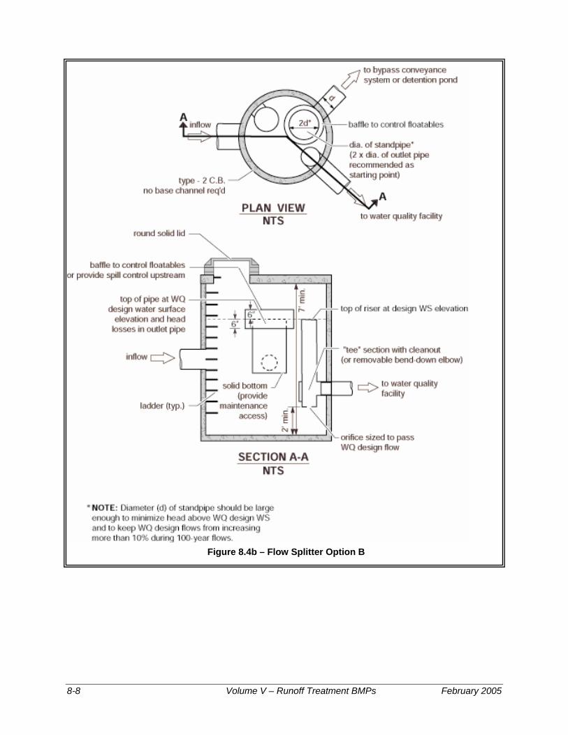
Figure 8.4b – Flow Splitter Option B
8-8 Volume V – Runoff Treatment BMPs February 2005

Figure 8.5 Example Isolation/Diversion Structure Source: City of Austin
WQ design flow rate (see Section 8.6)
Figure 8.5 – Example Isolation/Diversion Structure
February 2005 Volume V – Runoff Treatment BMPs 8-9

Figure 8.6a – Sand Filter Vault
8-10 Volume V – Runoff Treatment BMPs February 2005

(See Section 8.6) (on-line system)
Figure 8.6b – Sand Filter Vault (cont)
February 2005 Volume V – Runoff Treatment BMPs 8-11

Figure 8.7 – Linear Sand Filter
8-12 Volume V – Runoff Treatment BMPs February 2005

8.3 Performance Objectives Basic sand filter: Basic sand filters are expected to achieve the performance goals for Basic Treatment. Based upon experience in King County and Austin, Texas basic sand filters should be capable of achieving the following average pollutant removals: • 80 percent TSS at influent Event Mean Concentrations (EMCs) of 30-
300 mg/L (King County, 1998) (Chang, 2000)
• oil and grease to below 10 mg/L daily average and 15 mg/L at any time, with no ongoing or recurring visible sheen in the discharge.
Large sand filter: Large sand filters are expected to remove at least 50 percent of the total phosphorous compounds (as TP) by collecting and treating 95% of the runoff volume. (ASCE and WEF, 1998)
8.4 Applications and Limitations
Sand filtration can be used in most residential, commercial, and industrial developments where debris, heavy sediment loads, and oils and greases will not clog or prematurely overload the sand, or where adequate pretreatment is provided for these pollutants. Specific applications include residential subdivisions, parking lots for commercial and industrial establishments, gas stations, high-use sites, high-density multi family housing, roadways, and bridge decks.
Sand filters should be located off-line before or after detention (Chang, 2000). Sand filters are also suited for locations with space constraints in retrofit, and new/re-development situations. Overflow or bypass structures must be carefully designed to handle the larger storms. An off-line system is sized to treat 91% runoff volume predicted by a continuous runoff model. If a project must comply with Minimum Requirement #7, Flow Control, the flows bypassing the filter and the filter discharge must be routed to a retention/detention facility.
Pretreatment is necessary to reduce velocities to the sand filter and remove debris, floatables, large particulate matter, and oils. In high water table areas adequate drainage of the sand filter may require additional engineering analysis and design considerations. An underground filter should be considered in areas subject to freezing conditions. (Urbonas, 1997)
8.5 Site Suitability The following site characteristics should be considered in siting a sand filtration system: • Space availability, including a presettling basin
• Sufficient hydraulic head, at least 4 feet from inlet to outlet
February 2005 Volume V – Runoff Treatment BMPs 8-13

• Adequate Operation and Maintenance capability including accessibility for O & M
• Sufficient pretreatment of oil, debris and solids in the tributary runoff
8.6 Design Criteria Objective: To capture and treat the Water Quality Design Storm volume which is 91% of the total runoff volume (95% for large sand filter) as predicted by Western Washington Hydrology Model (WWHM) (or an approved, equivalent continuous runoff model).Only 9% of the total runoff volume (5% for large sand filter) would bypass or overflow from the sand filter facility . Off-line sand filters can be located either upstream or downstream of detention facilities. On-line sand filters should only be located downstream of detention to prevent exposure of the sand filter surface to high flow rates that could cause loss of media and previously removed pollutants.
Basic Sand Filter: A summary of the basic sand filter design requirements are given below. For off-line facilities, a flow splitter should be designed to route the water quality design flow rate to the sand filter.
On-line sand filters must NOT be placed upstream of a detention facility. This is to prevent exposure of the sand filter surface to high flow rates that could cause loss of media and previously removed pollutants.
On-line sand filters placed downstream of a detention facility must be sized using a continuous runoff model (WWHM or an approved equivalent model) to filter 91% of the runoff volume.
Off-line sand filters placed upstream of a detention facility must have a flow splitter designed to send all flows at or below the 15-minute water quality flow rate, as predicted by WWHM, to the sand filter. The sand filter must be sized to filter all the runoff sent to it (no overflows from the treatment facility should occur). Note that WWHM2 allows any bypasses and the runoff filtered through the sand to be directed to the downstream detention facility.
Off-line sand filters placed downstream of a detention facility must have a flow splitter designed to send all flows at or below the 2-year flow frequency from the detention pond, as predicted by WWHM, to the treatment facility. The treatment facility must be sized to filter all the runoff sent to it (no overflows from the treatment facility should occur).
.
8-14 Volume V – Runoff Treatment BMPs February 2005
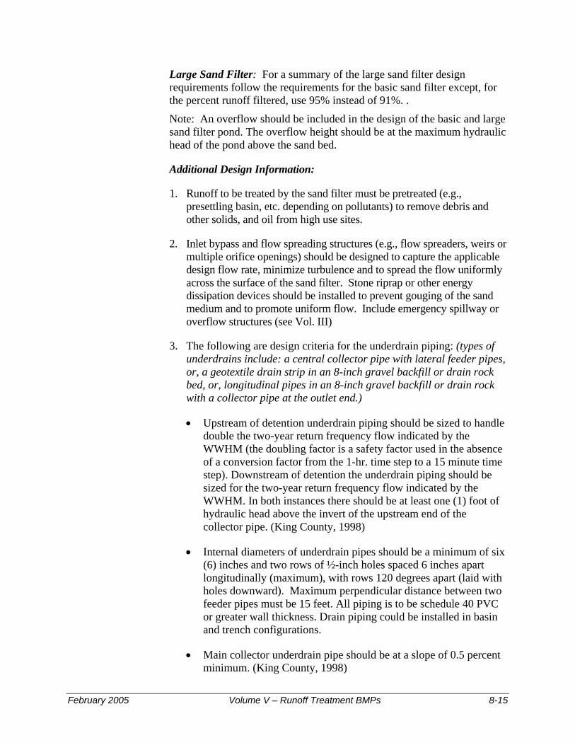
Large Sand Filter: For a summary of the large sand filter design requirements follow the requirements for the basic sand filter except, for the percent runoff filtered, use 95% instead of 91%. .
Note: An overflow should be included in the design of the basic and large sand filter pond. The overflow height should be at the maximum hydraulic head of the pond above the sand bed.
Additional Design Information:
1. Runoff to be treated by the sand filter must be pretreated (e.g., presettling basin, etc. depending on pollutants) to remove debris and other solids, and oil from high use sites.
2. Inlet bypass and flow spreading structures (e.g., flow spreaders, weirs or multiple orifice openings) should be designed to capture the applicable design flow rate, minimize turbulence and to spread the flow uniformly across the surface of the sand filter. Stone riprap or other energy dissipation devices should be installed to prevent gouging of the sand medium and to promote uniform flow. Include emergency spillway or overflow structures (see Vol. III)
3. The following are design criteria for the underdrain piping: (types of underdrains include: a central collector pipe with lateral feeder pipes, or, a geotextile drain strip in an 8-inch gravel backfill or drain rock bed, or, longitudinal pipes in an 8-inch gravel backfill or drain rock with a collector pipe at the outlet end.)
• Upstream of detention underdrain piping should be sized to handle double the two-year return frequency flow indicated by the WWHM (the doubling factor is a safety factor used in the absence of a conversion factor from the 1-hr. time step to a 15 minute time step). Downstream of detention the underdrain piping should be sized for the two-year return frequency flow indicated by the WWHM. In both instances there should be at least one (1) foot of hydraulic head above the invert of the upstream end of the collector pipe. (King County, 1998)
• Internal diameters of underdrain pipes should be a minimum of six (6) inches and two rows of ½-inch holes spaced 6 inches apart longitudinally (maximum), with rows 120 degrees apart (laid with holes downward). Maximum perpendicular distance between two feeder pipes must be 15 feet. All piping is to be schedule 40 PVC or greater wall thickness. Drain piping could be installed in basin and trench configurations.
• Main collector underdrain pipe should be at a slope of 0.5 percent minimum. (King County, 1998)
February 2005 Volume V – Runoff Treatment BMPs 8-15

• A geotextile fabric (specifications in Appendix V-C) must be used between the sand layer and drain rock or gravel and placed so that 1-inch of drain rock/gravel is above the fabric. Drain rock should be 0.75-1.5 inch rock or gravel backfill, washed free of clay and organic material. (King County, 1998)
Cleanout wyes with caps or junction boxes must be provided at both ends of the collector pipes. Cleanouts must extend to the surface of the filter. A valve box must be provided for access to the cleanouts. Access for cleaning all underdrain piping should be provided. This may consist of installing cleanout ports, which tee into the underdrain system and surface above the top of the sand bed. To facilitate maintenance of the sand filter an inlet shutoff/bypass valve is recommended.
Note: Other equivalent energy dissipaters can be used if needed.
4. Sand specification: The sand in a filter must consist of a medium sand meeting the size gradation (by weight) given in Table 8.1 below. The contractor must obtain a grain size analysis from the supplier to certify that the No. 100 and No. 200 sieve requirements are met. (Note: Standard backfill for sand drains, Wa. Std. Spec. 9-03.13, does not meet this specification and should not be used for sand filters.)
Table 8.1 – Sand Medium Specification U.S. Sieve Number Percent Passing
4 95-100 8 70-100
16 40-90 30 25-75 50 2-25
100 <4 200 <2
Source: King County Surface Water Design Manual, September 1998
8-16 Volume V – Runoff Treatment BMPs February 2005

5. Impermeable Liners for Sand Bed Bottom: Impermeable liners are generally required for soluble pollutants such as metals and toxic organics and where the underflow could cause problems with structures. Impermeable liners may be clay, concrete or geomembrane. Clay liners should have a minimum thickness of 12 inches and meet the specifications give in Table 8.2:
Table 8.2 – Clay Liner Specifications
Property Test Method Unit Specification
Permeability ASTM D-2434 cm/sec 1 x 10⁻⁶ max.
Plasticity Index of Clay ASTM D-423 & D-424
percent Not less than 15
Liquid Limit of Clay ASTM D-2216 percent Not less than 30
Clay Particles Passing ASTM D-422 percent Not less than 30
Clay Compaction ASTM D-2216 percent 95% of Standard Proctor Density
Source: City of Austin, 1988
• If a geomembrane liner is used it should have a minimum thickness of 30 mils and be ultraviolet resistant. The geomembrane liner should be protected from puncture, tearing, and abrasion by installing geotextile fabric on the top and bottom of the geomembrane.
• Concrete liners may also be used for sedimentation chambers and for sedimentation and sand filtration basins less than 1,000 square feet in area. Concrete should be 5 inches thick Class A or better and should be reinforced by steel wire mesh. The steel wire mesh should be 6 gauge wire or larger and 6-inch by 6-inch mesh or smaller. An "Ordinary Surface Finish" is required. When the underlying soil is clay or has an unconfined compressive strength of 0.25 ton per square foot or less, the concrete should have a minimum 6-inch compacted aggregate base. This base must consist of coarse sand and river stone, crushed stone or equivalent with diameter of 0.75- to 1-inch.
• If an impermeable liner is not required then a geotextile fabric liner should be installed that retains the sand and meets the specifications listed in Appendix V-C unless the basin has been excavated to bedrock.
• If an impermeable liner is not provided, then an analysis should be made of possible adverse effects of seepage zones on ground water, and near building foundations, basements, roads, parking lots and sloping sites. Sand filters without impermeable liners should not be built on fill sites and should be located at least 20-foot downslope and 100-foot upslope from building foundations.
February 2005 Volume V – Runoff Treatment BMPs 8-17
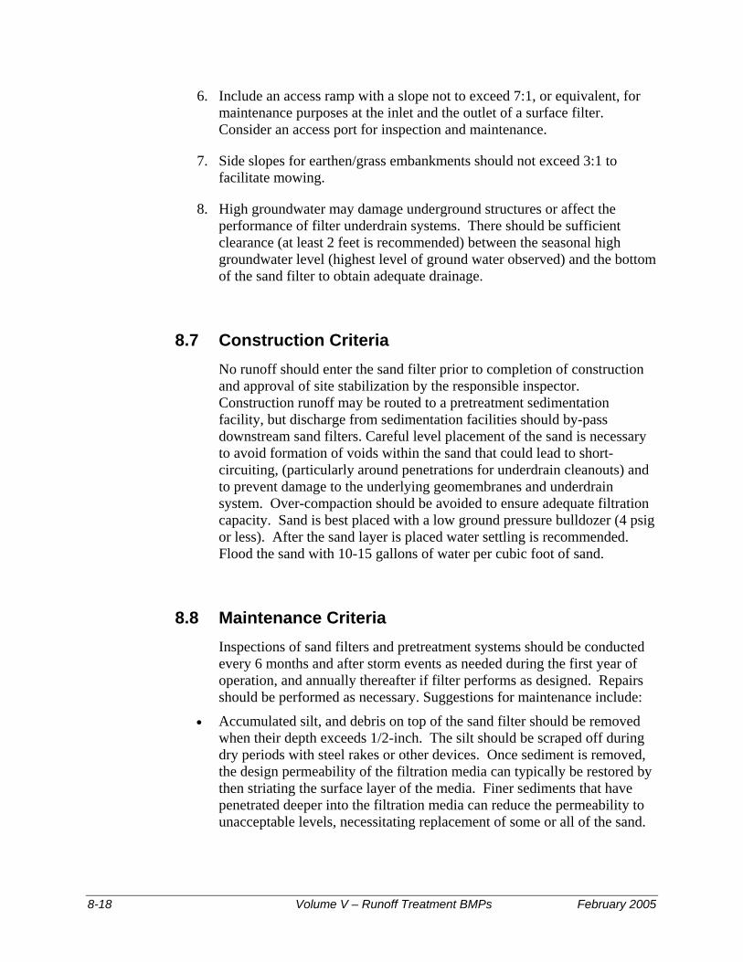
6. Include an access ramp with a slope not to exceed 7:1, or equivalent, for maintenance purposes at the inlet and the outlet of a surface filter. Consider an access port for inspection and maintenance.
7. Side slopes for earthen/grass embankments should not exceed 3:1 to facilitate mowing.
8. High groundwater may damage underground structures or affect the performance of filter underdrain systems. There should be sufficient clearance (at least 2 feet is recommended) between the seasonal high groundwater level (highest level of ground water observed) and the bottom of the sand filter to obtain adequate drainage.
8.7 Construction Criteria No runoff should enter the sand filter prior to completion of construction and approval of site stabilization by the responsible inspector. Construction runoff may be routed to a pretreatment sedimentation facility, but discharge from sedimentation facilities should by-pass downstream sand filters. Careful level placement of the sand is necessary to avoid formation of voids within the sand that could lead to short-circuiting, (particularly around penetrations for underdrain cleanouts) and to prevent damage to the underlying geomembranes and underdrain system. Over-compaction should be avoided to ensure adequate filtration capacity. Sand is best placed with a low ground pressure bulldozer (4 psig or less). After the sand layer is placed water settling is recommended. Flood the sand with 10-15 gallons of water per cubic foot of sand.
8.8 Maintenance Criteria Inspections of sand filters and pretreatment systems should be conducted every 6 months and after storm events as needed during the first year of operation, and annually thereafter if filter performs as designed. Repairs should be performed as necessary. Suggestions for maintenance include:
• Accumulated silt, and debris on top of the sand filter should be removed when their depth exceeds 1/2-inch. The silt should be scraped off during dry periods with steel rakes or other devices. Once sediment is removed, the design permeability of the filtration media can typically be restored by then striating the surface layer of the media. Finer sediments that have penetrated deeper into the filtration media can reduce the permeability to unacceptable levels, necessitating replacement of some or all of the sand.
8-18 Volume V – Runoff Treatment BMPs February 2005
• Sand replacement frequency is not well established and will depend on suspended solids levels entering the filter (the effectiveness of the pretreatment BMP can be a significant factor).
• Frequent overflow into the spillway or overflow structure or slow drawdown are indicators of plugging problems. A sand filter should empty in 24 hours following a storm event (24 hours for the pre-settling chamber), depending on pond depth. If the hydraulic conductivity drops to one (1) inch per hour corrective action is needed, e.g.:
− Scraping the top layer of fine-grain sediment accumulation (mid-winter scraping is suggested)
− Removal of thatch − Aerating the filter surface − Tilling the filter surface (late-summer rototilling is suggested) − Replacing the top 4 inches of sand. − Inspecting geotextiles for clogging
• Rapid drawdown in the sand bed (greater than 12 inches per hour) indicates short-circuiting of the filter. Inspect the cleanouts on the underdrain pipes and along the base of the embankment for leakage.
• Drawdown tests for the sand bed could be conducted, as needed, during the wet season. These tests can be conducted by allowing the filter to fill (or partially fill) during a storm event, then measuring the decline in water level over a 4-8 hour period. An inlet and an underdrain outlet valve would be necessary to conduct such a test.
• Formation of rills and gullies on the surface of the filter indicates improper function of the inlet flow spreader, or poor sand compaction. Check for accumulation of debris on or in the flow spreader and refill rills and gullies with sand.
• Avoid driving heavy equipment on the filter to prevent compaction and rut formation.
February 2005 Volume V – Runoff Treatment BMPs 8-19

BMP T8.10 Sand Filter Vault
Description: (Figures 8.6a and 8.6b)
A sand filter vault is similar to an open sand filter except that the sand layer and underdrains are installed below grade in a vault. It consists of presettling and sand filtration cells.
Applications and Limitations
• Use where space limitations preclude above ground facilities
• Not suitable where high water table and heavy sediment loads are expected
• An elevation difference of 4 feet between inlet and outlet is needed
Additional Design Criteria for Vaults
• Vaults may be designed as off-line systems or on-line for small drainages
• In an off-line system a diversion structure should be installed to divert the design flow rate into the sediment chamber and bypass the remaining flow to detention/retention (if necessary to meet Minimum Requirement #7), or to surface water.
• Optimize sand inlet flow distribution with minimal sand bed disturbance. A maximum of 8-inch distance between the top of the spreader and the top of the sand bed is suggested. Flows may enter the sand bed by spilling over the top of the wall into a flow spreader pad or alternatively a pipe and manifold system may be used. Any pipe and manifold system must retain the required dead storage volume in the first cell, minimize turbulence, and be readily maintainable.
• If an inlet pipe and manifold system is used, the minimum pipe size should be 8 inches. Multiple inlets are recommended to minimize turbulence and reduce local flow velocities.
• Erosion protection must be provided along the first foot of the sand bed adjacent to the spreader. Geotextile fabric secured on the surface of the sand bed, or equivalent method, may be used.
• The filter bed should consist of a sand top layer, and a geotextile fabric second layer with an underdrain system.
• Design the presettling cell for sediment collection and removal. A V-shaped bottom, removable bottom panels, or equivalent sludge handling system should be used. One-foot of sediment storage in the presettling cell must be provided.
8-20 Volume V – Runoff Treatment BMPs February 2005

• The pre-settling chamber must be sealed to trap oil and trash. This chamber is usually connected to the sand filtration chamber through an invert elbow to protect the filter surface from oil and trash.
• If a retaining baffle is necessary for oil/floatables in the presettling cell, it must extend at least one foot above to one foot below the design flow water level. Provision for the passage of flows in the event of plugging must be provided. Access opening and ladder must be provided on both sides of the baffle.
• To prevent anoxic conditions, a minimum of 24 square feet of ventilation grate should be provided for each 250 square feet of sand bed surface area. For sufficient distribution of airflow across the sand bed, grates may be located in one area if the sand filter is small, but placement at each end is preferred. Small grates may also be dispersed over the entire sand bed area.
• Provision for access is the same as for wet vaults. Removable panels must be provided over the entire sand bed.
• Sand filter vaults must conform to the materials and structural suitability criteria specified for wet vaults.
• Provide a sand filter inlet shutoff/bypass valve for maintenance
• A geotextile fabric over the entire sand bed may be installed that is flexible, highly permeable, three-dimensional matrix, and adequately secured. This is useful in trapping trash and litter.
February 2005 Volume V – Runoff Treatment BMPs 8-21

BMP T8.20 Linear Sand Filter
Description: (Figure 8.7)
Linear sand filters are typically long, shallow, two-celled, rectangular vaults. The first cell is designed for settling coarse particles, and the second cell contains the sand bed. Stormwater flows into the second cell via a weir section that also functions as a flow spreader.
Application and Limitations
• Applicable in long narrow spaces such as the perimeter of a paved surface.
• As a part of a treatment train as downstream of a filter strip, upstream of an infiltration system, or upstream of a wet pond or a biofilter for oil control.
• To treat small drainages (less than 2 acres of impervious area).
• To treat runoff from high-use sites for TSS and oil/grease removal, if applicable.
Additional Design Criteria for Linear Sand Filters
• The two cells should be divided by a divider wall that is level and extends a minimum of 12 inches above the sand bed.
• Stormwater may enter the sediment cell by sheet flow or a piped inlet.
• The width of the sand cell must be 1-foot minimum to 15 feet maximum.
• The sand filter bed must be a minimum of 12 inches deep and have an 8-inch layer of drain rock with perforated drainpipe beneath the sand layer.
• The drainpipe must be 6-inch diameter minimum and be wrapped in geotextile and sloped a minimum of 0.5 percent.
• Maximum sand bed ponding depth: 1-foot.
• Must be vented as for sand filter vaults
• Linear sand filters must conform to the materials and structural suitability criteria specified for wet vaults.
• Set sediment cell width as follows:
Sand filter width, (w) inches 12-24 24-48 48-72 72+
Sediment cell width, inches 12 18 24 w/3
8-22 Volume V – Runoff Treatment BMPs February 2005
Chapter 9 - Biofiltration Treatment Facilities Note: Figures in Chapter 9 are courtesy of King County, except as noted
This Chapter addresses five Best Management Practices (BMPs) that are classified as biofiltration treatment facilities:
Biofilters are vegetated treatment systems (typically grass) that remove pollutants by means of sedimentation, filtration, soil sorption, and/or plant uptake. They are typically configured as swales or flat filter strips.
9.1 Purpose The BMPs discussed in this Chapter are designed to remove low concentrations and quantities of total suspended solids (TSS), heavy metals, petroleum hydrocarbons, and/or nutrients from stormwater.
9.2 Applications A biofilter can be used as a basic treatment BMP for contaminated stormwater runoff from roadways, driveways, parking lots, and highly impervious ultra-urban areas or as the first stage of a treatment train. In cases where hydrocarbons, high TSS, or debris would be present in the runoff, such as high-use sites, a pretreatment system for those components would be necessary. Off-line location is preferred to avoid flattening vegetation and the erosive effects of high flows. Biofilters should be considered in retrofit situations where appropriate. (Center for Watershed Protection, 1998)
9.3 Site Suitability The following factors must be considered for determining site suitability: • Target pollutants are amenable to biofilter treatment • Accessibility for Operation and Maintenance • Suitable growth environment; (soil, etc.) for the vegetation • Adequate siting for a pre-treatment facility if high petroleum
hydrocarbon levels (oil/grease) or high TSS loads could impair treatment capacity or efficiency
• If the biofilter can be impacted by snowmelts and ice, refer to Caraco and Claytor for additional design criteria (USEPA, 1997).
February 2005 Volume V – Runoff Treatment BMPs 9-1

9.4 Best Management Practices This Chapter presents the following Biofiltration Treatment BMPs:
BMP T9.10 – Basic Biofiltration Swale BMP T9.20 - Wet Biofiltration Swale BMP T9.30 – Continuous Inflow Biofiltration Swale BMP T9.40 – Basic Filter Strip & Compost-Amended Filter Strip BMP T9.50 – Narrow Area Filter Strip
BMP T9.10 Basic Biofiltration Swale Description:
Biofiltration swales are typically shaped as a trapezoid or a parabola as shown in Figure 9.1.
Figure 9.1 – Typical Swale Section
Limitations:
Data suggest that the performance of biofiltration swales is highly variable from storm to storm. It is therefore recommended that treatment methods providing more consistent performance, such as sand filters and wet ponds, be considered first. Swales downstream of devices of equal or greater effectiveness can convey runoff but should not be expected to offer a treatment benefit. (Horner, 2000)
9-2 Volume V – Runoff Treatment BMPs February 2005

Design Criteria:
• Design criteria are specified in Table 9.1. A 9 minute hydraulic residence time is used at a multiple of the peak 15 minute Water Quality Design Flow Rate (Q) representing 91% runoff volume as determined by the Western Washington Hydrology Model (WWHM). (See Volume I)
• Check the hydraulic capacity/stability for inflows greater than design flows. Bypass high flows, or control release rates into the biofilter, if necessary.
• Install level spreaders (min. 1-inch gravel) at the head and every 50 feet in swales of ≥4 feet width. Include sediment cleanouts (weir, settling basin, or equivalent) at the head of the biofilter as needed.
• Use energy dissipators (riprap) for increased downslopes.
Guidance for Bypassing Off-line Facilities:
Most biofiltration swales are currently designed to be on-line facilities. However, an off-line design is possible. Swales designed in an off-line mode should not engage a bypass until the flow rate exceeds a value determined by multiplying Q, the off-line water quality design flow rate predicted by the WWHM, by the ratio determined in Figure 9.5b. This modified design flow rate is an estimate of the design flow rate determined by using SBUH procedures. Ecology’s intent is to maintain recent biofiltration sizing recommendations (9 minutes detention at the peak design flow rate estimated by SBUH for a 6-month, 24-hour storm with a Type 1A rainfall distribution) until more definitive information is collected concerning bioswale performance. The only advantage of designing a swale to be off-line is that the stability check, which may make the swale larger, is not necessary.
Sizing Procedure for Biofiltration Swales
This guide provides biofilter swale design procedures in full detail, along with examples.
Preliminary Steps (P)
P-1 Determine the Water Quality design flow rate (Q) in 15-minute time-steps using the WWHM. Use the correct flow rate, off-line or on-line, for your design situation.
P-2 Establish the longitudinal slope of the proposed biofilter.
P-3 Select a vegetation cover suitable for the site. Refer to Tables 9.2, 9.3, and 9.4 (in text) to select vegetation for western Washington.
February 2005 Volume V – Runoff Treatment BMPs 9-3

Design Calculations for Biofiltration Swale
There are a number of ways of applying the design procedure introduced by Chow (Chow, 1959). These variations depend on the order in which steps are performed, what constants are established at the beginning of the process and which ones are calculated, and what values are assigned to the variables selected initially.
The procedure recommended here is an adaptation appropriate for biofiltration applications of the type being installed in the Puget Sound region. This procedure reverses Chow's order, designing first for capacity and then for stability. The capacity analysis emphasizes the promotion of biofiltration, rather than transporting flow with the greatest possible hydraulic efficiency. Therefore, it is based on criteria that promote sedimentation, filtration, and other pollutant removal mechanisms. Because these criteria include a lower maximum velocity than permitted for stability, the biofilter dimensions usually do not have to be modified after a stability check.
Design Steps (D):
D-1. Select the type of vegetation, and design depth of flow (based on frequency of mowing and type of vegetation). (Table 9.1)
D-2. Select a value of Manning's n (Table 9.1 with footnote #3).
Table 9.1 – Sizing Criteria Design parameter BMP T 9.10-Biofiltration swale BMP T 9.40-Filter strip Longitudinal Slope 0.015 - 0.0251 0.01 - 0.15
Maximum velocity
1 ft / sec ( @ K multiplied by the WQ design flow rate ;
for stability, 3 ft/sec max. 0.5 ft / sec
Maximum water depth22”- if mowed frequently; 4” if mowed infrequently 1-inch max.
Manning coefficient (22) (0.2 – 0.3)3(0.24 if mowed
infrequently) 0.35 (0.45 if compost-amended, and
mowed to maintain grass height ≤ 4”) Bed width (bottom) (2 - 10 ft)4 --- Freeboard height 0.5 ft --- Minimum hydraulic residence time at Water Quality Design Flow Rate
9 minutes (18 minutes for continuous inflow)
(See Volume I, Appendix B) 9 minutes
Minimum length 100 ft Sufficient to achieve hydraulic residence time in the filter strip
Maximum sideslope 3 H : 1 V
4H:1V preferred Inlet edge ≥ 1” lower than contributing
paved area Max. tributary drainage flowpath --- 150 feet Max. longitudinal slope of contributing area ---
0.05 (steeper than 0.05 need upslope flow spreading and energy dissipation)
Max. lateral slope of contributing area --- 0.02 (at the edge of the strip inlet)
9-4 Volume V – Runoff Treatment BMPs February 2005

1. For swales, if the slope is less than 1.5% install an underdrain using a perforated pipe, or equivalent. Amend the soil if necessary to allow effective percolation of water to the underdrain. Install the low-flow drain 6” deep in the soil. Slopes greater than 2.5% need check dams (riprap) at vertical drops of 12-15 inches. Underdrains can be made of 6 inch Schedule 40 PVC perforated pipe with 6” of drain gravel on the pipe. The gravel and pipe must be enclosed by geotextile fabric. (See Figures 9.2 and 9.3)
2 Below the design water depth install an erosion control blanket, at least 4” of topsoil, and the selected biofiltration mix. Above the water line use a straw mulch or sod.
3. This range of Manning’s n can be used in the equation; b = Qn/1.49y(1.67) s(0.5) – Zy with wider bottom width b, and lower depth, y, at the same flow. This provides the designer with the option of varying the bottom width of the swale depending on space limitations. Designing at the higher n within this range at the same flow decreases the hydraulic design depth, thus placing the pollutants in closer contact with the vegetation and the soil.
4. For swale widths up to 16 feet the cross-section can be divided with a berm (concrete, plastic, compacted earthfill) using a flow spreader at the inlet (Figure 9.4)
Figure 9.2 – Biofiltration Swale Underdrain Detail
Figure 9.3 – Biofiltration Swale Low-Flow Drain Detail
February 2005 Volume V – Runoff Treatment BMPs 9-5

Figure 9.4 Swale Dividing Berm
Figure 9.4 – Swale Dividing Berm
D-3. Select swale shape-typically trapezoidal or parabolic.
D-4. Use Manning's equation and first approximations relating hydraulic radius and dimensions for the selected swale shape to obtain a working value of a biofilter width dimension:
Q 1.49AR0
=s
n
.67 0.5
(1)
yA T= (2) rectangle
TyT 2y
=+
(3) R rectangle
9-6 Volume V – Runoff Treatment BMPs February 2005

W
Q 5-minute time steps based
tio of vertical
imensionless)
t) of a rectangle (ft)
y = depth of flow (ft)
gnizing that T>>y and Z²>>1, and that certain terms are nearly negligible. The approximation solutions
Substitute Rtrapezoid and Atrapezoid = by+Zy2 into Equation 1, and solve for the bottom width b (trapezoidal swale):
here:
= Water Quality Design flow rate in 1on WWHM, (ft³/s, cfs) n = Manning's n (dimensionless) s = Longitudinal slope as a ra rise/horizontal run (dA = Cross-sectional area (ft²) R = Hydraulic radius (fT = top width of trapezoid or width
b = bottom width of trapezoid (ft)
If equations 2 and 3 are substituted into equation 1 and solved for T, complex equations result that are difficult to solve manually. However, approximate solutions can be found by reco
for rectangular and trapezoidal shapes are:
Rrectangle ≈ y, Rtrapezoid ≈ y, Rparabolic ≈ 0.67y, Rv ≈ 0.5y
b 2.5Qn1.49y s1.67 0.5 Zy≈ −
top r
he SBUH design flow. This equation is used to estimate an initial cross-sectional
reduced, divide the flow by installing a low berm, or arbitrarily set b = 10 ft and continue with the analysis. For other swale shapes refer to Fig. 9.5.
For a trapezoid, select a side slope Z of at least 3. Compute b and then width T, where T = b + 2yZ. (Note: Adjustment factor of 2.5 accounts fothe differential between Water Quality design flow rate and t
area. It does not affect the overall biofiltration swale size.)
If b for a swale is greater than 10 ft, either investigate how Q can be
February 2005 Volume V – Runoff Treatment BMPs 9-7

Figure 9.5 – Geometric Formulas for Common Swale Shapes
Source: Livingston, et al, 1984
9-8 Volume V – Runoff Treatment BMPs February 2005

D-5. Compute A:
A Tyerectangl = or ZyA bytrapazoid2= +
Afilter strip = Ty
D-6. Compute the flow velocity at design flow rate:
K = A ratio of the peak 10-minute flow predicted by SBUH to the water quality design flow rate estimated using the WWHM. The value of K is determined from Figure 9.6a for on-line facilities, or Figure 9.6b for off-line facilities.
If V >1.0 ft/sec (or V>0.5 ft/sec for a filter strip), repeat steps D-1 to D-6 until the condition is met. A velocity greater than 1.0 ft/sec was found to flatten grasses, thus reducing filtration. A velocity lower than this maximum value will allow a 9-minute hydraulic residence time criterion in a shorter biofilter. If the value of V suggests that a longer biofilter will be needed than space permits, investigate how Q can be reduced (e.g., use of low impact development BMP’s), or increase y and/or T (up to the allowable maximum values) and repeat the analysis.
D-7. Compute the swale length (L, ft)
L = Vt (60 sec/min)
Where: t = hydraulic residence time (min)
Use t = 9 minutes for this calculation (use t = 18 minutes for a continuous inflow biofiltration swale). If a biofilter length is greater than the space permits, follow the advice in step D-6.
If a length less than 100 feet results from this analysis, increase it to 100 feet, the minimum allowed. In this case, it may be possible to save some space in width and still meet all criteria. This possibility can be checked by computing V in the 100 ft biofilter for t = 9 minutes, recalculating A (if V < 1.0 ft/sec) and recalculating T.
D-8. If there is still not sufficient space for the biofilter, the local government and the project proponent should consider the following solutions (listed in order of preference):
1) Divide the site drainage to flow to multiple biofilters. 2) Use infiltration to provide lower discharge rates to the biofilter (only if
the Site Suitability Criteria in Chapter 3, Volume III are met). 3) Increase vegetation height and design depth of flow (note: the design
must ensure that vegetation remains standing during design flow).
Q=κV A
February 2005 Volume V – Runoff Treatment BMPs 9-9

SBUH Peak/WWHM On-Line 15-min WQ Flow Ratio vs 6-Month Precipitation for 0% to 100% Impervious Areas
4.5 4.0 3.5 R
a 3.0 t
i 2.5 o 2.0
1.5 1.0 0.5 0.0
0.0 0.5 1.0 3.5 1.5 2.0 2.5 3.0 4.06-month, 24-hr precipitation (72% of 2-year), Inches
(K)
Figure 9.6a – Ratio of SBUH Peak/WQ Flow
SBUH Peak/WWHM Off-Line 15-min WQ Flow Ratio vs 6-Month Precipitation for 0% to 100% Impervious Areas
8.0
7.0 R a 6.0 t i 5.0 o 4.0 (K)
3.0
2.0
1.0
0.0 0.0 0.5 1.0 3.5 1.5 2.0 2.5 3.0 4.0
6-month, 24-hr precipitation (72% of 2-year), Inches
Figure 9.6b – Ratio of SBUH Peak/WQ Flow
4) Reduce the developed surface area to gain space for biofiltration. 5) Increase the longitudinal slope.
9-10 Volume V – Runoff Treatment BMPs February 2005

6) Increase the side slopes. 7) Nest the biofilter within or around another BMP.
Check for Stability (Minimizing Erosion)
The stability check must be performed for the combination of highest expected flow and least vegetation coverage and height. A check is not required for biofiltration swales that are located "off-line" from the primary conveyance/detention system, Maintain the same units as in the biofiltration capacity analysis.
SC-1. Perform the stability check for the 100-year, return frequency flow using 15-minute time steps using an approved continuous runoff model. Until WWHM peak flow rates in 15-minute time steps are available the designer can use the WWHM 100-yr. hourly peak flows times an adjustment factor of 1.6 to approximate peak flows in 15-minute time steps.
SC-2. Estimate the vegetation coverage ("good" or "fair") and height on the first occasion that the biofilter will receive flow, or whenever the coverage and height will be least. Avoid flow introduction during the vegetation establishment period by timing planting or bypassing.
SC-3. Estimate the degree of retardance from Table 9.2. When uncertain, be conservative by selecting a relatively low degree.
The maximum permissible velocity for erosion prevention (Vmax) is 3 feet per second.
Stability Check Steps (SC)
Table 9.2 – Guide for Selecting Degree of Retardance (a)
Coverage Average Grass Height (inches) Degree of Retardance
Good <2 E. Very Low 2-6 D. Low 6-10 C. Moderate 11-24 B. High >30 A. Very High Fair <2 E. Very Low 2-6 D. Low 6-10 D. Low 11-24 C. Moderate >30 B. High
See Chow (1959).. In addition, Chow recommended selection of retardance C for a grass-legume mixture 6-8 inches high and D for a mixture 4-5 inches high. No retardance recommendations have appeared for emergent wetland species. Therefore, judgment must be used. Since these species generally grow less densely than grasses, using a "fair" coverage would be a reasonable approach.
February 2005 Volume V – Runoff Treatment BMPs 9-11

SC-4. Select a trial Manning's n for the high flow condition. The minimum value for poor vegetation cover and low height (possibly, knocked from the vertical by high flow) is 0.033. A good initial choice under these conditions is 0.04.
Source: Livingston, et al, 1984
VR (feet 2/second)
Figure 9.7 – The Relationship of Manning’s n with VR for Various Degrees of Flow Retardance (A-E) SC-5. Refer to Figure 9.7 to obtain a first approximation for VR of 3 feet/second.
SC-6. Compute hydraulic radius, R, from VR in Figure 9.7 and a Vmax
SC-7. Use Manning’s equation to solve for the actual VR.
SC-8. Compare the actual VR from step SC-7 and first approximation from step SC-5. If they do not agree within 5 percent, repeat steps SC-4 to SC-8 until acceptable agreement is reached. If n<0.033 is needed to get agreement, set n = 0.033, repeat step SC-7, and then proceed to step SC-9.
9-12 Volume V – Runoff Treatment BMPs February 2005

SC-9. Compute the actual V for the final design conditions:
Check to be sure V < Vmax of 3 feet/second.
SC-10. Compute the required swale cross-sectional area, A, for stability:
SC-11. Compare the A, computed in step SC-10 of the stability analysis, with the A from the biofiltration capacity analysis (step D-5).
If less area is required for stability than is provided for capacity, the capacity design is acceptable. If not, use A from step SC-10 of the stability analysis and recalculate channel dimensions.
SC-12. Calculate the depth of flow at the stability check design flow rate condition for the final dimensions and use A from step SC-10.
SC-13. Compare the depth from step SC-12 to the depth used in the biofiltration capacity design (Step D-1). Use the larger of the two and add 0.5 ft. of freeboard to obtain the total depth (yt) of the swale. Calculate the top width for the full depth using the appropriate equation.
SC-14. Recalculate the hydraulic radius: (use b from Step D-4 calculated previously for biofiltration capacity, or Step SC-11, as appropriate, and yt = total depth from Step SC-13)
SC-15. Make a final check for capacity based on the stability check design storm (this check will ensure that capacity is adequate if the largest expected event coincides with the greatest retardance). Use Equation 1, a Manning's n selected in step D-2, and the calculated channel dimensions, including freeboard, to compute the flow capacity of the channel under these conditions. Use R from step SC-14, above, and A = b(yt) + Z(yt)² using b from Step D-4, D-15, or SC-11 as appropriate.
If the flow capacity is less than the stability check design storm flow rate, increase the channel cross-sectional area as needed for this conveyance. Specify the new channel dimensions.
Completion Step (CO) CO. Review all of the criteria and guidelines for biofilter planning, design, installation, and operation above and specify all of the appropriate features for the application.
February 2005 Volume V – Runoff Treatment BMPs 9-13

Example of Design Calculations for Biofiltration Swales
Preliminary Steps
P-1. Assume that the WWHM based Water Quality Design Flow Rate in 15 minute time-steps, Q, is 0.2 cfs. Assume an on-line facility.
P-2. Assume the slope (s) is 2 percent.
P-3. Assume the vegetation will be a grass-legume mixture and it will be infrequently mowed.
Design for Biofiltration Swale Capacity
D-1. Set winter grass height at 5" and the design flow depth (y) at 3 inches.
D-2. Use n = 0.20 to n2 = 0.30
D-3. Base the design on a trapezoidal shape, with a side slope Z = 3.
D-4a. Calculate the bottom width, b;
Where:
n = 0.20 y = 0.25 ft Q = 0.2 cfs s = 0.02 Z = 3
b 2.5Qn1.49y s
Zy1.67 0.5≈ −
b 4.0 ft≈ At n2; b2 = 6.5 feet
D-4b. Calculate the top width (T)
T = b + 2yZ = 4.0+ [2(0.25)(3)] = 5.5 feet
D-5. Calculate the cross-sectional area (A)
A = by + Zy² = (4.0)(0.25) + (3)(0.252) = 1.19 ft²
D-6. Calculate the flow velocity (V) V
QA
0 . 1 7 f t / s e c= Κ =
for K = 1. Actual K is determined per Figure 9.5a
0.17<1.0 ft/sec ∴ OK
9-14 Volume V – Runoff Treatment BMPs February 2005

D-7 Calculate the Length (L)
L = Vt(60 sec/min)
= 0.17 (9)(60)
For t = 9 min, L = 92 ft. at n; expand to a minimum of 100 foot length per design criterion
At n2; L = 100 ft.
Note: Where b is less than the maximum value, it may be possible to reduce L by increasing b. In this case, because L is determined by the requirement for a minimum length of 100 feet, it is not possible.
Check for Channel Stability
SC-1. Base the check on passing the 100-year, return frequency flow (15 minute time steps) through a swale with a mixture of Kentucky bluegrass and tall fescue on loose erodible soil. Until WWHM peak flow rates in 15-minute time steps are available the designer can use the WWHM 100-yr. hourly peak flows times an adjustment factor of 1.6 to approximate peak flows in 15-minute time steps. Assume that the adjusted peak Q is 1.92 cfs.
SC-2. Base the check on a grass height of 3 inches with "fair" coverage (lowest mowed height and least cover, assuming flow bypasses or does not occur during grass establishment).
SC-3. From Table 9.2, Degree of Retardance = D (low) Set Vmax = 3 ft/sec
SC-4. Select trial Manning's n = 0.04
SC-5. From Figure 9.7, VRappx = 3 ft²/s
SC-6. Calculate R
VR appx
SC-7. Calculate VRactual
SC-8. VRactual from step SC-7 > VRappx from step SC-5 by > 5%.
Select new trial n = 0.0475 Figure 9.7: VRappx = 1.7 ft²/s
= =R 1.0 ftV max
1.49VR n
R1.67s0.5 2= = /5.25 ft secactual
February 2005 Volume V – Runoff Treatment BMPs 9-15

R = 0.57 ft. VRactual = 1.73 ft²/s (within 5% of VRappx = 1.7)
SC-9. Calculate V
V = 3 ft/sec < 3 ft/sec, Vmax∴OK
SC-10. Calculate Stability Area
SC-11. Stability Check
AStability = 0.64 ft² is less than ACapacity from step D-5 (ACapacity = 1.19 ft2). ∴OK
If AStability > ACapacity, it will be necessary to select new trial sizes for width and flow depth (based on space and other considerations), recalculate ACapacity, and repeat steps SC-10 and SC-11.
SC-12. Calculate depth of flow at the stability design flow rate condition using the quadratic equation solution:
y b b -4 Z (-A )2 Z
2
=− ± −
For b = 4, y = 0.14 ft (positive root)
SC-13. Use the greater value of y from SC-12 or that assumed in D-1. In this case, the greater depth is 0.25-foot, which was the basis for the biofiltration capacity design. Add 0.5 feet freeboard to that depth.
Total channel depth = 0.75 ft Top Width = b + 2yZ = 4 + (2)(0.75)(3) = 8.5 ft
SC-14. Recalculate hydraulic radius and flow rate
For b = 4 ft, y = 0.75 ft Z = 3, s = 0.02, n = 0.2 A = by + Zy² = 4.68 ft² R = {by + Zy²}/{b + 2y(Z² + 1)0.5} = 0.53 ft.
VR 1.73= = =actualV / 3 ft secR 0.57
Q 1.92A V 3
0.64 ft2= = =Stability
9-16 Volume V – Runoff Treatment BMPs February 2005

SC-15. Calculate Flow Capacity at Greatest Resistance
Q 1.49AR sn
0.67 0.5
= = 3.2 cfs
Q = 3.2 cfs > 1.92 cfs ∴OK Completion Step
CO-1. Assume 100 feet of swale length is available.
The final channel dimensions are:
Bottom width, b = 4 feet Channel depth= 0.75 feet Top width = b + 2yZ = 8.5 feet
No check dams are needed for a 2% slope.
Soil Criteria
• The following top soil mix at least 8-inch deep:
– Sandy loam 60-90 % – Clay 0-10 % – Composted organic matter, 10-30 %
(excluding animal waste, toxics)
• Use compost amended soil where practicable
• Till to at least 8-inch depth
• For longitudinal slopes of < 2 percent use more sand to obtain more infiltration
• If ground water contamination is a concern, seal the bed with clay or a geomembrane liner
Vegetation Criteria
• See Tables 9.3, 9.4 and 9.5 for recommended grasses, wetland plants, and groundcovers.
• Select fine, turf-forming, water-resistant grasses where vegetative growth and moisture will be adequate for growth.
• Irrigate if moisture is insufficient during dry weather season.
• Use sod with low clay content and where needed to initiate adequate vegetative growth. Preferably sod should be laid to a minimum of one-foot vertical depth above the swale bottom.
• Consider sun/shade conditions for adequate vegetative growth and avoid prolonged shading of any portion not planted with shade tolerant vegetation.
February 2005 Volume V – Runoff Treatment BMPs 9-17

• Stabilize soil areas upslope of the biofilter to prevent erosion
• Fertilizing a biofilter should be avoided if at all possible in any application where nutrient control is an objective. Test the soil for nitrogen, phosphorous, and potassium and consult with a landscape professional about the need for fertilizer in relation to soil nutrition and vegetation requirements. If use of a fertilizer cannot be avoided, use a slow-release fertilizer formulation in the least amount needed.
Recommended grasses (see Tables 9.3 and 9.4 below)
Table 9.3 – Grass Seed Mixes Suitable for Biofiltration Swale Treatment Areas
Mix 1 Mix 2 75-80 percent tall or meadow fescue 60-70 percent tall fescue 10-15 percent seaside/colonial
bentgrass 10-15 percent seaside/colonial bentgrass
5-10 percent Redtop 10-15 percent meadow foxtail 6-10 percent alsike clover 1-5 percent marshfield big trefoil 1-6 percent Redtop Note: all percentages are by weight. * based on Briargreen, Inc.
Table 9.4 – Groundcovers And Grasses Suitable for the Upper Side Slopes of a Biofiltration Swale in Western Washington
Groundcovers kinnikinnick* Arctostaphylos uva-ursi St. John’s-wort Hypericum perforatum Epimedium Epimedium grandiflorum creeping forget-me-not Omphalodes verna -- Euonymus lanceolata yellow-root Xanthorhiza simplissima -- Genista white lawn clover Trifolium repens white sweet clover* Melilotus alba ------- Rubus calycinoides strawberry* Fragaria chiloensis broadleaf lupine* Lupinus latifolius
Grasses (drought-tolerant, minimum mowing) dwarf tall fescues Festuca spp. (e.g., Many Mustang, Silverado) hard fescue Festuca ovina duriuscula (e.g., Reliant, Aurora) tufted fescue Festuca amethystine buffalo grass Buchloe dactyloides red fescue* Festuca rubra tall fescue grass* Festuca arundinacea blue oatgrass Helictotrichon sempervirens
9-18 Volume V – Runoff Treatment BMPs February 2005

Construction Criteria
The biofiltration swale should not be put into operation until areas of exposed soil in the contributing drainage catchment have been sufficiently stabilized. Deposition of eroded soils can impede the growth of grass in the swale and reduce swale treatment effectiveness. Thus, effective erosion and sediment control measures should remain in place until the swale vegetation is established (see Volume II for erosion and sediment control BMPs). Avoid compaction during construction. Grade biofilters to attain uniform longitudinal and lateral slopes
Maintenance Criteria
• Inspect biofilters at least once every 6 months, preferably during storm events, and also after storm events of > 0.5 inch rainfall/ 24 hours. Maintain adequate grass growth and eliminate bare spots.
• Mow grasses, if needed for good growth {typically maintain at 4 – 9 inches and not below design flow level (King County, 1998)}.
• Remove sediment as needed at head of the swale if grass growth is inhibited in greater than 10 percent of the swale, or if the sediment is blocking the distribution and entry of the water (King County, 1998).
• Remove leaves, litter, and oily materials, and re-seed or resod, and regrade, as needed. Clean curb cuts and level spreaders as needed.
Prevent scouring and soil erosion in the biofilter. If flow channeling occurs, regrade and reseed the biofilter, as necessary.
Maintain access to biofilter inlet, outlet, and to mowing (Figure 9.8)
• If a swale is equipped with underdrains, vehicular traffic on the swale bottom (other than grass mowing equipment) should be avoided to prevent damage to the drainpipes.
February 2005 Volume V – Runoff Treatment BMPs 9-19

Figure 9.8 – Biofiltration Swale Access Features
9-20 Volume V – Runoff Treatment BMPs February 2005

BMP T9.20 Wet Biofiltration Swale
Description
A wet biofiltration swale is a variation of a basic biofiltration swale for use where the longitudinal slope is slight, water tables are high, or continuous low base flow is likely to result in saturated soil conditions. Where saturation exceeds about 2 weeks, typical grasses will die. Thus, vegetation specifically adapted to saturated soil conditions is needed. Different vegetation in turn requires modification of several of the design parameters for the basic biofiltration swale.
Performance Objectives
To remove low concentrations of pollutants such as TSS, heavy metals, nutrients, and petroleum hydrocarbons.
Applications/Limitations
Wet biofiltration swales are applied where a basic biofiltration swale is desired but not allowed or advisable because one or more of the following conditions exist:
• The swale is on till soils and is downstream of a detention pond providing flow control.
• Saturated soil conditions are likely because of seeps or base flows on the site.
• Longitudinal slopes are slight (generally less than 2 percent).
Design Criteria
Use the same design approach as for basic biofiltration swales except to add the following:
Adjust for extended wet season flow. If the swale will be downstream of a detention pond providing flow control, multiply the treatment area (bottom width times length) of the swale by 2, and readjust the swale length, if desired. Maintain a 5:1 length to width ratio.
Intent: An increase in the treatment area of swales following detention ponds is required because of the differences in vegetation established in a constant flow environment. Flows following detention are much more prolonged. These prolonged flows result in more stream-like conditions than are typical for other wet biofilter situations. Since vegetation growing in streams is often less dense, this increase in treatment area is needed to ensure that equivalent pollutant removal is achieved in extended flow situations.
February 2005 Volume V – Runoff Treatment BMPs 9-21

Swale Geometry: Same as specified for basic biofiltration swales except for the following modifications:
Criterion 1: The bottom width may be increased to 25 feet maximum, but a length-to-width ratio of 5:1 must be provided. No longitudinal dividing berm is needed. Note: The minimum swale length is still 100 feet.
Criterion 2: If longitudinal slopes are greater than 2 percent, the wet swale must be stepped so that the slope within the stepped sections averages 2 percent. Steps may be made of retaining walls, log check dams, or short riprap sections. No underdrain or low-flow drain is required.
High-Flow Bypass: A high-flow bypass (i.e., an off-line design) is required for flows greater than the off-line water quality design flow that has been increased by the ratio indicated in Figure 9.5b. The bypass is necessary to protect wetland vegetation from damage. Unlike grass, wetland vegetation will not quickly regain an upright attitude after being laid down by high flows. New growth, usually from the base of the plant, often taking several weeks, is required to regain its upright form. The bypass may be an open channel parallel to the wet biofiltration swale. Water Depth and Base Flow: Same as for basic biofiltration swales except the design water depth shall be 4 inches for all wetland vegetation selections, and no underdrains or low-flow drains are required.
Flow Velocity, Energy Dissipation, and Flow Spreading: Same as for basic biofiltration swales except no flow spreader is needed.
Access: Same as for basic biofiltration swales except access is only required to the inflow and the outflow of the swale; access along the length of the swale is not required. Also, wheel strips may not be used for access in the swale.
Intent: An access road is not required along the length of a wet swale because of infrequent access needs. Frequent mowing or harvesting is not desirable. In addition, wetland plants are fairly resilient to sediment-induced changes in water depth, so the need for access should be infrequent.
Soil Amendment: Same as for basic biofiltration swales.
Planting Requirements: Same as for basic biofiltration swales except for the following modifications:
1. A list of acceptable plants and recommended spacing is shown in Table 9.5. In general, it is best to plant several species to increase the
9-22 Volume V – Runoff Treatment BMPs February 2005

likelihood that at least some of the selected species will find growing conditions favorable.
2. A wetland seed mix may be applied by hydroseeding, but if coverage is poor, planting of rootstock or nursery stock is required. Poor coverage is considered to be more than 30 percent bare area through the upper 2/3 of the swale after four weeks.
Recommended Design Features: Same as for basic biofiltration swales
Construction Considerations: Same as for basic biofiltration swales
Maintenance Considerations: Same as for basic biofiltration swales except mowing of wetland vegetation is not required. However, harvesting of very dense vegetation may be desirable in the fall after plant die-back to prevent the sloughing of excess organic material into receiving waters. Many native Juncus species remain green throughout the winter; therefore, fall harvesting of Juncus species is not recommended.
Table 9.5 – Recommended Plants for Wet Biofiltration Swale Common Name Scientific Name Spacing (on center)
Shortawn foxtail Alopecurus aequalis seed Water foxtail Alopecurus geniculatus seed Spike rush Eleocharis spp. 4 inches Slough sedge* Carex obnupta 6 inches or seed Sawbeak sedge Carex stipata 6 inches Sedge Carex spp. 6 inches Western mannagrass Glyceria occidentalis seed Velvetgrass Holcus mollis seed Slender rush Juncus tenuis 6 inches Watercress* Rorippa nasturtium-aquaticum 12 inches Water parsley* Oenanthe sarmentosa 6 inches Hardstem bulrush Scirpus acutus 6 inches Small-fruited bulrush Scirpus microcarpus 12 inches
* Good choices for swales with significant periods of flow, such as those downstream of a detention facility. Note: Cattail (Typha latifolia) is not appropriate for most wet swales because of its very dense and clumping growth habit which prevents water from filtering through the clump.
February 2005 Volume V – Runoff Treatment BMPs 9-23

BMP T9.30 Continuous Inflow Biofiltration Swale Description
In situations where water enters a biofiltration swale continuously along the side slope rather than discretely at the head, a different design approach–the continuous inflow biofiltration swale–is needed. The basic swale design is modified by increasing swale length to achieve an equivalent average residence time.
Applications
A continuous inflow biofiltration swale is to be used when inflows are not concentrated, such as locations along the shoulder of a road without curbs. This design may also be used where frequent, small point flows enter a swale, such as through curb inlet ports spaced at intervals along a road, or from a parking lot with frequent curb cuts. In general, no inlet port should carry more than about 10 percent of the flow.
A continuous inflow swale is not appropriate for a situation in which significant lateral flows enter a swale at some point downstream from the head of the swale. In this situation, the swale width and length must be recalculated from the point of confluence to the discharge point in order to provide adequate treatment for the increased flows.
Design Criteria
Same as specified for basic biofiltration swale except for the following:
• The design flow for continuous inflow swales must include runoff from the pervious side slopes draining to the swale along the entire swale length. Therefore, they must be on-line facilities.
• If only a single design flow is used, the flow rate at the outlet should be used. The goal is to achieve an average residence time through the swale of 9 minutes as calculated using the on-line water quality design flow rate multiplied by the ratio, K, in Figure 9.5a. Assuming an even distribution of inflow into the side of the swale double the hydraulic residence time to a minimum of 18 minutes.
• For continuous inflow biofiltration swales, interior side slopes above the WQ design treatment elevation shall be planted in grass. A typical lawn seed mix or the biofiltration seed mixes are acceptable. Landscape plants or groundcovers other than grass may not be used anywhere between the runoff inflow elevation and the bottom of the swale.Intent: The use of grass on interior side slopes reduces the chance of soil erosion and transfer of pollutants from landscape areas to the biofiltration treatment area.
9-24 Volume V – Runoff Treatment BMPs February 2005
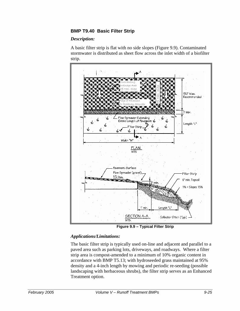
BMP T9.40 Basic Filter Strip Description:
A basic filter strip is flat with no side slopes (Figure 9.9). Contaminated stormwater is distributed as sheet flow across the inlet width of a biofilter strip.
Contributing Drainage Area 2% Max. Slope
5%
Max
. Slo
pe
Edge of Pavement Or Roadway Shoulder
6” min. Topsoil 1% < Slopes 15%
Figure 9.9 – Typical Filter Strip
Applications/Limitations: The basic filter strip is typically used on-line and adjacent and parallel to a paved area such as parking lots, driveways, and roadways. Where a filter strip area is compost-amended to a minimum of 10% organic content in accordance with BMP T5.13; with hydroseeded grass maintained at 95% density and a 4-inch length by mowing and periodic re-seeding (possible landscaping with herbaceous shrubs), the filter strip serves as an Enhanced Treatment option.
February 2005 Volume V – Runoff Treatment BMPs 9-25

Design Criteria for Filter strips:
• Use the Design Criteria specified in Table 9.1
• Filter strips should only receive sheet flow.
• Use curb cuts ≥ 12-inch wide and 1-inch above the filter strip inlet.
Calculate the design flow depth using Manning’s equation as follows:
KQ = (1.49A R0.67 s 0.5)/n
Substituting for AR:
KQ = (1.49Ty1.67 s0.5)/n
Where:
Ty = Arectangle, ft2
y ≈ Rrectangle, design depth of flow, ft. (1 inch maximum) Q = peak Water Quality design flow rate based on WWHM, ft3/sec (See Appendix I-B, Volume I) K = The ratio determined by using Figure 9.5a
n = Manning’s roughness coefficient s = Longitudinal slope of filter strip parallel to direction of flow T = Width of filter strip perpendicular to the direction of flow, ft. A = Filter strip inlet cross-sectional flow area (rectangular), ft2
R = hydraulic radius, ft.
Rearranging for y:
y = [KQn/1.49Ts0.5]0.6
y must not exceed 1 inch
Note: As in swale design an adjustment factor of K accounts for the differential between the WWHM Water Quality design flow rate and the SBUH design flow
Calculate the design flow velocity V, ft./sec., through the filter strip:
V = KQ/Ty V must not exceed 0.5 ft./sec
Calculate required length, ft., of the filter strip at the minimum hydraulic residence time, t, of 9 minutes:
L = tV = 540V
9-26 Volume V – Runoff Treatment BMPs February 2005

BMP T9.50 Narrow Area Filter Strip Description:
This section describes a filter strip design1 for impervious areas with flowpaths of 30 feet or less that can drain along their widest dimension to grassy areas.
Applications/Limitations:
A narrow area filter strip could be used at roadways with limited right-of-way, or for narrow parking strips, the narrow strip. If space is available to use the basic filter strip design, that design should be used in preference to the narrow filter strip.
The treatment objectives, applications and limitations, design criteria, materials specifications, and construction and maintenance requirements set forth in the basic filter strip design apply to narrow filter strip applications.
Design Criteria:
Design criteria for narrow area filter strips are the same as specified for basic filter strips. The sizing of a narrow area filter strip is based on the length of flowpath draining to the filter strip and the longitudinal slope of the filter strip itself (parallel to the flowpath).
Step 1: Determine the length of the flowpath from the upstream to the downstream edge of the impervious area draining sheet flow to the strip. Normally this is the same as the width of the paved area, but if the site is sloped, the flow path may be longer than the width of the impervious area.
Step 2: Calculate the longitudinal slope of the filter strip (along the direction of unconcentrated flow), averaged over the total width of the filter strip. The minimum sizing slope is 2 percent. If the slope is less than 2 percent, use 2 percent for sizing purposes. The maximum allowable filter strip slope is 20 percent. If the slope exceeds 20 percent, the filter strip must be stepped down the slope so that the treatment areas between drop sections do not have a longitudinal slope greater than 20 percent. Drop sections must be provided with erosion protection at the base and flow spreaders to re-spread flows. Vertical drops along the slope must not exceed 12 inches in height. If this is not possible, a different treatment facility must be selected.
1 This narrow area filter strip design method is included here because technical limitations exist in the basic design method which result in filter strips that are proportionately longer as the contributing drainage becomes narrower (a result that is counter-intuitive). Research by several parties is underway to evaluate filter strip design parameters. This research may lead to more stringent design requirements that would supersede the design criteria presented here.
February 2005 Volume V – Runoff Treatment BMPs 9-27

Step 3: Select the appropriate filter strip length for the flowpath length and filter strip longitudinal slope (Steps 1 and 2 above) from the graph in Figure 9.10. The filter strip must be designed to provide this minimum length L along the entire stretch of pavement draining into it.
To use the graph: Find the length of the flowpath on one of the curves (interpolate between curves as necessary). Move along the curve to the point where the design longitudinal slope of the filter strip (x-axis) is directly below. Read the filter strip length on the y-axis which corresponds to the intersection point.
Figure 9.10 – Filter Strip Lengths for Narrow Right-of-Way
0.0
5.0
10.0
15.0
20.0
0% 5% 10% 15% 20%
Filter Strip Slope
Filte
r St
rip
Len
gth
(fee
t)
Note: minimum allowable filter strip length is 4 feet
Flowpath = 30 feet
20 feet
10 feet
9-28 Volume V – Runoff Treatment BMPs February 2005

Chapter 10 - Wetpool Facilities Note: Figures in Chapter 10 are from the King County Surface Water Design Manual
10.1 Purpose
This Chapter presents the methods, criteria, and details for analysis and design of wetponds, wetvaults, and stormwater wetlands. These facilities have as a common element a permanent pool of water - the wetpool. Each of the wetpool facilities can be combined with a detention or flow control pond in a combined facility. Included are the following specific facility designs:
BMP T10.10 - Wetponds - Basic and Large BMP T10.20 - Wetvaults BMP T10.30 - Stormwater Wetlands BMP T10.40 - Combined Detention and Wetpool Facilities
10.2 Application
The wetpool facility designs described for the four BMPs in this Chapter will achieve the performance objectives cited in Chapter 3 for specific treatment menus.
10.3 Best Management Practices (BMPs) for Wetpool Facilities
The four BMPs discussed below are currently recognized as effective treatment techniques using wetpool facilities. The specific BMPs that are selected should be coordinated with the Treatment Facility Menus discussed in Chapter 3.
BMP T10.10 Wetponds - Basic and Large
Purpose and Definition
A wetpond is a constructed stormwater pond that retains a permanent pool of water ("wetpool") at least during the wet season. The volume of the wetpool is related to the effectiveness of the pond in settling particulate pollutants. As an option, a shallow marsh area can be created within the permanent pool volume to provide additional treatment for nutrient removal. Peak flow control can be provided in the "live storage" area above the permanent pool. Figures 10-1a and 1b illustrates a typical wet pond BMP.
The following design, construction, and operation and maintenance criteria cover two wetpond applications - the basic wetpond and the large wetpond. Large wetponds are designed for higher levels of pollutant removal.
February 2005 Volume V – Runoff Treatment BMPs 10-1

Figure 10.1a – Wetpond
������
berm or baffle at design WS or submerged 1’ below design W.S. Extend berm across entirewetpool width.
plantings required on cut slopes for lake protection facilities
emergency spillway per detention facility requirements
FIRST WETPOOL CELL25% to 35% of wetpool volume,
excluding access ramp
access ramp to bottom of firstwetpool cell (7H: 1V) (see text)
SECOND WETPOOL CELL
emergency overflow WS
overflow WS wetpoolwidth
PLAN VIEWNTS
inlet pipe & catch basin perdetention facility requirements
outlet erosion control & energy dissipation per detention facility requirements
manhole & outlet pipe pie sized to pass peak flow perconveyance requirements
A
A
B
B
WQ design WS
berm top width 5’ min. (if earthen)
access road to outlet structure
access road to inlet structure
New Design ManualFigure 6.4.1.B WetpondRevised 4-15-97, mdev
NOTE: Berm not required for ponds with length to width ratio ≥ 4:1 or if volume less than 4000 c.f.
10-2 Volume V – Runoff Treatment BMPs February 2005

������������������������������������������������������������������������������������������������������������������������������������
yyyyyyyyyyyyyyyyyyyyyyyyyyyyyyyyyyyyyyyyyyyyyyyyyyyyyyyyyyyyyyyyyyyyyyyyyyyyyyyyyyyyyyyyyyyyyyyyyyyyyyyyyyyyyyyyyyyyyyyyyyyyyyyyyyyy
������������������������
yyyyyyyyyyyyyyyyyyyyyyyy
������������������������������������
yyyyyyyyyyyyyyyyyyyyyyyyyyyyyyyyyyyy
����������������������yyyyyyyyyyyyyyyyyyyyyy
NOTE: See detention facilityrequirements for location and setback requirements.
Invert 6” min. below top of internal
berm. Lower placement
is desirable.
emergency overflow WS
gravity drain(if grade allows) 8” min. diameter
18” min.
exterior berms designed perdam safety requirementsif applicable
capacity of outlet system sized to pass peak flow for conveyance req.
fence required for side slopes steeper than 3(V): 1(H)
W.Q. design WS
manhole ortype 2catch basin
outlet pipe invert at wetpool WS elevation
access road
valve(may be located inside MH
or outside with approvedoperational access)
SECTION B-BNTS
sediment storagedepth = 1’ min.
slope vegetationper detention
facility requirements
inlet erosion control/slope protection per
detention facilityrequirements
first celldepth 4’ min.to 8’ max.
wetpool depth 8’ max. recirculation recommended for depth > 6’
emergent vegetationrequired for wetpooldepths 3’ or less
Note: Berm slope may be2:1 when top submerged 1’ below WQ design WS
2’ min.
keyed
emergency overflow WS
Inlet
wetpool flow length = 3 (min.) x width
SECTION A-ANTS
1ft
WQ design WSoverflow WS
overflow WS
New Design ManualFigure 6.4.1.B. Wetpond (continued)Revised 4-30-97, mdev
12” min.
Figure 10.1b – Wetpond
Applications and Limitations A wetpond requires a larger area than a biofiltration swale or a sand filter, but it can be integrated to the contours of a site fairly easily. In till soils, the wetpond holds a permanent pool of water that provides an attractive aesthetic feature. In more porous soils, wetponds may still be used, but water seepage from unlined cells could result in a dry pond, particularly in the summer months. Lining the first cell with a low permeability liner is one way to deal with this situation. As long as the first cell retains a
February 2005 Volume V – Runoff Treatment BMPs 10-3

permanent pool of water, this situation will not reduce the pond’s effectiveness but may be an aesthetic drawback.
Wetponds work best when the water already in the pond is moved out en masse by incoming flows, a phenomenon called "plug flow." Because treatment works on this displacement principle, the wetpool storage of wetponds may be provided below the groundwater level without interfering unduly with treatment effectiveness. However, if combined with a detention function, the live storage must be above the seasonal high groundwater level.
Wetponds may be single-purpose facilities, providing only runoff treatment, or they may be combined with a detention pond to also provide flow control. If combined, the wetpond can often be stacked under the detention pond with little further loss of development area. See BMP T10.40 for a description of combined detention and wetpool facilities.
Design Criteria The primary design factor that determines a wetpond's treatment efficiency is the volume of the wetpool. The larger the wetpool volume, the greater the potential for pollutant removal. For a basic wetpond, the wetpool volume provided shall be equal to or greater than the total volume of runoff from the water quality design storm - the 6-month, 24-hour storm event. Alternatively, the 91st percentile, 24-hour runoff volume indicated by an approved continuous runoff model. A large wetpond requires a wetpool volume at least 1.5 times larger than the total volume of runoff from the 6-month, 24-hour storm event. Also important are the avoidance of short-circuiting and the promotion of plug flow. Plug flow describes the hypothetical condition of stormwater moving through the pond as a unit, displacing the "old" water in the pond with incoming flows. To prevent short-circuiting, water is forced to flow, to the extent practical, to all potentially available flow routes, avoiding "dead zones" and maximizing the time water stays in the pond during the active part of a storm.
Design features that encourage plug flow and avoid dead zones are:
• Dissipating energy at the inlet. • Providing a large length-to-width ratio. • Providing a broad surface for water exchange using a berm designed
as a broad-crested weir to divide the wetpond into two cells rather than a constricted area such as a pipe.
• Maximizing the flowpath between inlet and outlet, including the vertical path, also enhances treatment by increasing residence time.
10-4 Volume V – Runoff Treatment BMPs February 2005

Sizing Procedure
Procedures for determining a wetpond's dimensions and volume are outlined below.
Step 1: Identify required wetpool volume using the SCS (now known as NRCS) curve number equations presented in Volume III, Chapter 2, Section 2.3.2. A basic wetpond requires a volume equal to or greater than the total volume of runoff from the 6-month, 24-hour storm event. Alternatively, use the 91st percentile, 24-hour runoff volume indicated by an approved continuous runoff model. A large wetpond requires a volume at least 1.5 times the total volume of runoff from the 6-month, 24-hour storm event, or 1.5 times the 91st percentile, 24-hour runoff volume indicated by an approved continuous runoff model. Step 2: Determine wetpool dimensions. Determine the wetpool dimensions satisfying the design criteria outlined below and illustrated in Figures 10.1a and 10.1b. A simple way to check the volume of each wetpool cell is to use the following equation:
V = h A A( + )1 2
2
where V = wetpool volume (cf) h = wetpool average depth (ft) A1 = water quality design surface area of wetpool (sf) A2 = bottom area of wetpool (sf)
Step 3: Design pond outlet pipe and determine primary overflow water surface. The pond outlet pipe shall be placed on a reverse grade from the pond's wetpool to the outlet structure. Use the following procedure to design the pond outlet pipe and determine the primary overflow water surface elevation:
a) Use the nomographs in Figures 10.2 and 10.3 to select a trial size for the pond outlet pipe sufficient to pass the on-line WQ design flow, Qwq indicated by WWHM or other approved continuous runoff model.
b) Use Figure 10.4 to determine the critical depth dc at the outflow end of the pipe for Qwq.
c) Use Figure 10.5 to determine the flow area Ac at critical depth. d) Calculate the flow velocity at critical depth using continuity equation
(Vc = Qwq /Ac). e) Calculate the velocity head VH (VH =Vc
2 /2g, where g is the gravitational constant, 32.2 feet per second).
f) Determine the primary overflow water surface elevation by adding the velocity head and critical depth to the invert elevation at the outflow end of the pond outlet pipe (i.e., overflow water surface elevation = outflow invert + dc + VH).
February 2005 Volume V – Runoff Treatment BMPs 10-5

g) Adjust outlet pipe diameter as needed and repeat Steps (a) through (e).
Step 4: Determine wetpond dimensions. General wetpond design criteria and concepts are shown in Figure 10.1a and 10.1b.
Wetpool Geometry • The wetpool shall be divided into two cells separated by a baffle or
berm. The first cell shall contain between 25 to 35 percent of the total wetpool volume. The baffle or berm volume shall not count as part of the total wetpool volume. The term baffle means a vertical divider placed across the entire width of the pond, stopping short of the bottom. A berm is a vertical divider typically built up from the bottom, or if in a vault, connects all the way to the bottom.
Intent: The full-length berm or baffle promotes plug flow and enhances quiescence and laminar flow through as much of the entire water volume as possible. Alternative methods to the full-length berm or baffle that provide equivalent flow characteristics may be approved on a case-by-case basis by the Local Plan Approval Authority.
• Sediment storage shall be provided in the first cell. The sediment storage shall have a minimum depth of 1-foot. A fixed sediment depth monitor should be installed in the first cell to gauge sediment accumulation unless an alternative gauging method is proposed.
• The minimum depth of the first cell shall be 4 feet, exclusive of sediment storage requirements. The depth of the first cell may be greater than the depth of the second cell.
• The maximum depth of each cell shall not exceed 8 feet (exclusive of sediment storage in the first cell). Pool depths of 3 feet or shallower (second cell) shall be planted with emergent wetland vegetation (see Planting requirements).
• Inlets and outlets shall be placed to maximize the flowpath through the facility. The ratio of flowpath length to width from the inlet to the outlet shall be at least 3:1. The flowpath length is defined as the distance from the inlet to the outlet, as measured at mid-depth. The width at mid-depth can be found as follows: width = (average top width + average bottom width)/2.
• Wetponds with wetpool volumes less than or equal to 4,000 cubic feet may be single celled (i.e., no baffle or berm is required). However, it is especially important in this case that the flow path length be maximized. The ratio of flow path length to width shall be at least 4:1 in single celled wetponds, but should preferably be 5:1.
• All inlets shall enter the first cell. If there are multiple inlets, the length-to-width ratio shall be based on the average flowpath length for all inlets.
10-6 Volume V – Runoff Treatment BMPs February 2005
• The first cell may be lined in accordance with the liner requirements contained in Section 4.4.
Berms, Baffles, and Slopes • A berm or baffle shall extend across the full width of the wetpool, and
tie into the wetpond side slopes. If the berm embankments are greater than 4 feet in height, the berm must be constructed by excavating a key equal to 50 percent of the embankment cross-sectional height and width. This requirement may be waived if recommended by a geotechnical engineer for specific site conditions. The geotechnical analysis shall address situations in which one of the two cells is empty while the other remains full of water.
• The top of the berm may extend to the WQ design water surface or be 1-foot below the WQ design water surface. If at the WQ design water surface, berm side slopes should be 3H:1V. Berm side slopes may be steeper (up to 2:1) if the berm is submerged 1-foot.
Intent: Submerging the berm is intended to enhance safety by discouraging pedestrian access when side slopes are steeper than 3H:1V. An alternative to the submerged berm design is the use of barrier planting to prevent easy access to the divider berm in an unfenced wetpond.
• If good vegetation cover is not established on the berm, erosion control measures should be used to prevent erosion of the berm back-slope when the pond is initially filled.
• The interior berm or baffle may be a retaining wall provided that the design is prepared and stamped by a licensed civil engineer. If a baffle or retaining wall is used, it should be submerged one foot below the design water surface to discourage access by pedestrians.
• Criteria for wetpond side slopes are included in Section 4.3.
Embankments Embankments that impound water must comply with the Washington State Dam Safety Regulations (Chapter 173-175 WAC). If the impoundment has a storage capacity (including both water and sediment storage volumes) greater than 10 acre-feet (435,600 cubic feet or 3.26 million gallons) above natural ground level, then dam safety design and review are required by the Department of Ecology. See Section 3.2.1 of Volume III.
Inlet and Outlet See Figure 10.1a and 10.1b for details on the following requirements:
• The inlet to the wetpond shall be submerged with the inlet pipe invert a minimum of two feet from the pond bottom (not including sediment
February 2005 Volume V – Runoff Treatment BMPs 10-7

storage). The top of the inlet pipe should be submerged at least 1-foot, if possible.
Intent: The inlet is submerged to dissipate energy of the incoming flow. The distance from the bottom is set to minimize resuspension of settled sediments. Alternative inlet designs that accomplish these objectives are acceptable.
• An outlet structure shall be provided. Either a Type 2 catch basin with a grated opening (jail house window) or a manhole with a cone grate (birdcage) may be used (see Volume III, Figure 3.11 for an illustration). No sump is required in the outlet structure for wetponds not providing detention storage. The outlet structure receives flow from the pond outlet pipe. The grate or birdcage openings provide an overflow route should the pond outlet pipe become clogged. The overflow criteria provided below specifies the sizing and position of the grate opening.
• The pond outlet pipe (as opposed to the manhole or type 2 catch basin outlet pipe) shall be back-sloped or have a turn-down elbow, and extend 1 foot below the WQ design water surface. Note: A floating outlet, set to draw water from 1-foot below the water surface, is also acceptable if vandalism concerns are adequately addressed.
Intent: The inverted outlet pipe provides for trapping of oils and floatables in the wetpond.
• The pond outlet pipe shall be sized, at a minimum, to pass the on-line WQ design flow. Note: The highest invert of the outlet pipe sets the WQ design water surface elevation.
• The overflow criteria for single-purpose (treatment only, not combined with flow control) wetponds are as follows: a) The requirement for primary overflow is satisfied by either the
grated inlet to the outlet structure or by a birdcage above the pond outlet structure.
b) The bottom of the grate opening in the outlet structure shall be set at or above the height needed to pass the WQ design flow through the pond outlet pipe. Note: The grate invert elevation sets the overflow water surface elevation.
c) The grated opening should be sized to pass the 100-year design flow. The capacity of the outlet system should be sized to pass the peak flow for the conveyance requirements.
• An emergency spillway shall be provided and designed according to the requirements for detention ponds (see Section 3.2.1 of Volume III).
• The Local Plan Approval Authority may require a bypass/ shutoff valve to enable the pond to be taken offline for maintenance purposes.
• A gravity drain for maintenance is recommended if grade allows.
10-8 Volume V – Runoff Treatment BMPs February 2005
Intent: It is anticipated that sediment removal will only be needed for the first cell in the majority of cases. The gravity drain is intended to allow water from the first cell to be drained to the second cell when the first cell is pumped dry for cleaning.
• The drain invert shall be at least 6 inches below the top elevation of the dividing berm or baffle. Deeper drains are encouraged where feasible, but must be no deeper than 18 inches above the pond bottom.
Intent: To prevent highly sediment-laden water from escaping the pond when drained for maintenance.
• The drain shall be at least 8 inches (minimum) diameter and shall be controlled by a valve. Use of a shear gate is allowed only at the inlet end of a pipe located within an approved structure.
Intent: Shear gates often leak if water pressure pushes on the side of the gate opposite the seal. The gate should be situated so that water pressure pushes toward the seal.
• Operational access to the valve shall be provided to the finished ground surface.
• The valve location shall be accessible and well-marked with 1-foot of paving placed around the box. It must also be protected from damage and unauthorized operation.
• A valve box is allowed to a maximum depth of 5 feet without an access manhole. If over 5 feet deep, an access manhole or vault is required.
• All metal parts shall be corrosion-resistant. Galvanized materials should not be used unless unavoidable.
Intent: Galvanized metal contributes zinc to stormwater, sometimes in very high concentrations.
Access and Setbacks
• All facilities shall be a minimum of 20 feet from any structure, property line, and any vegetative buffer required by the local government, and 100 feet from any septic tank/drainfield.
• All facilities shall be a minimum of 50 feet from any steep (greater than 15 percent) slope. A geotechnical report must address the potential impact of a wet pond on a steep slope.
• Access and maintenance roads shall be provided and designed according to the requirements for detention ponds. Access and maintenance roads shall extend to both the wetpond inlet and outlet structures. An access ramp (7H minimum:1V) shall be provided to the bottom of the first cell unless all portions of the cell can be reached and sediment loaded from the top of the pond.
February 2005 Volume V – Runoff Treatment BMPs 10-9

• If the dividing berm is also used for access, it should be built to sustain loads of up to 80,000 pounds.
Planting Requirements Planting requirements for detention ponds also apply to wetponds.
• Large wetponds intended for phosphorus control should not be planted within the cells, as the plants will release phosphorus in the winter when they die off.
• If the second cell of a basic wetpond is 3 feet or shallower, the bottom area shall be planted with emergent wetland vegetation. See Table 10.1 for recommended emergent wetland plant species for wetponds. Intent: Planting of shallow pond areas helps to stabilize settled sediment and prevent resuspension.
Note: The recommendations in Table 10.1 are for western Washington only. Local knowledge should be used to adapt this information if used in other areas.
• Cattails (Typha latifolia) are not recommended because they tend to crowd out other species and will typically establish themselves anyway.
• If the wetpond discharges to a phosphorus-sensitive lake or wetland, shrubs that form a dense cover should be planted on slopes above the WQ design water surface on at least three sides. For banks that are berms, no planting is allowed if the berm is regulated by dam safety requirements. The purpose of planting is to discourage waterfowl use of the pond and to provide shading. Some suitable trees and shrubs include vine maple (Acer circinatum), wild cherry (Prunus emarginata), red osier dogwood (Cornus stolonifera), California myrtle (Myrica californica), Indian plum (Oemleria cerasiformis), and Pacific yew (Taxus brevifolia) as well as numerous ornamental species.
Recommended Design Features The following design features should be incorporated into the wetpond design where site conditions allow:
• The method of construction of soil/landscape systems can cause natural selection of specific plant species. Consult a soil restoration or wetland soil scientist for site-specific recommendations. The soil formulation will impact the plant species that will flourish or suffer on the site, and the formulation should be such that it encourages desired species and discourages undesired species.
• For wetpool depths in excess of 6 feet, it is recommended that some form of recirculation be provided in the summer, such as a fountain or aerator, to prevent stagnation and low dissolved oxygen conditions.
10-10 Volume V – Runoff Treatment BMPs February 2005

• A flow length-to-width ratio greater than the 3:1 minimum is desirable. If the ratio is 4:1 or greater, then the dividing berm is not required, and the pond may consist of one cell rather than two. A one-cell pond must provide at least 6-inches of sediment storage depth.
• A tear-drop shape, with the inlet at the narrow end, rather than a rectangular pond is preferred since it minimizes dead zones caused by corners.
• A small amount of base flow is desirable to maintain circulation and reduce the potential for low oxygen conditions during late summer.
• Evergreen or columnar deciduous trees along the west and south sides of ponds are recommended to reduce thermal heating, except that no trees or shrubs may be planted on berms meeting the criteria of dams regulated for safety. In addition to shade, trees and shrubs also discourage waterfowl use and the attendant phosphorus enrichment problems they cause. Trees should be set back so that the branches will not extend over the pond.
Intent: Evergreen trees or shrubs are preferred to avoid problems associated with leaf drop. Columnar deciduous trees (e.g., hornbeam, Lombardy poplar, etc.) typically have fewer leaves than other deciduous trees.
• The number of inlets to the facility should be limited; ideally there should be only one inlet. The flowpath length should be maximized from inlet to outlet for all inlets to the facility.
• The access and maintenance road could be extended along the full length of the wetpond and could double as playcourts or picnic areas. Placing finely ground bark or other natural material over the road surface would render it more pedestrian friendly.
• The following design features should be incorporated to enhance aesthetics where possible: − Provide pedestrian access to shallow pool areas enhanced with
emergent wetland vegetation. This allows the pond to be more accessible without incurring safety risks.
− Provide side slopes that are sufficiently gentle to avoid the need for fencing (3:1 or flatter).
− Create flat areas overlooking or adjoining the pond for picnic tables or seating that can be used by residents. Walking or jogging trails around the pond are easily integrated into site design.
− Include fountains or integrated waterfall features for privately maintained facilities.
− Provide visual enhancement with clusters of trees and shrubs. On most pond sites, it is important to amend the soil before planting since ponds are typically placed well below the native soil horizon
February 2005 Volume V – Runoff Treatment BMPs 10-11

in very poor soils. Make sure dam safety restrictions against planting do not apply.
− Orient the pond length along the direction of prevailing summer winds (typically west or southwest) to enhance wind mixing.
Construction Criteria
• Sediment that has accumulated in the pond must be removed after construction in the drainage area of the pond is complete (unless used for a liner - see below).
• Sediment that has accumulated in the pond at the end of construction may be used in excessively drained soils to meet the liner requirements if the sediment meets the criteria for low permeability or treatment liners in keeping with guidance in Chapter 4. Sediment used for a soil liner must be graded to provide uniform coverage and must meet the thickness specifications in Chapter 4. The sediment must not reduce the design volume of the pond. The pond must be over-excavated initially to provide sufficient room for the sediments to serve as a liner.
Operation and Maintenance
• Maintenance is of primary importance if wetponds are to continue to function as originally designed. A local government, a designated group such as a homeowners' association, or a property owner shall accept the responsibility for maintaining the structures and the impoundment area. A specific maintenance plan shall be formulated outlining the schedule and scope of maintenance operations.
• The pond should be inspected by the local government annually. The maintenance standards contained in Section 4.6 are measures for determining if maintenance actions are required as identified through the annual inspection.
• Site vegetation should be trimmed as necessary to keep the pond free of leaves and to maintain the aesthetic appearance of the site. Slope areas that have become bare should be revegetated and eroded areas should be regraded prior to being revegetated.
• Sediment should be removed when the 1-foot sediment zone is full plus 6 inches. Sediments should be tested for toxicants in compliance with current disposal requirements. Sediments must be disposed in accordance with current local health department requirements and the Minimum Functional Standards for Solid Waste Handling. See Volume IV, Appendix IV-G Recommendations for Management of Street Waste for additional guidance.
• Any standing water removed during the maintenance operation must be properly disposed of. The preferred disposal option is discharge to a sanitary sewer at an approved location. Other disposal options include discharge back into the wetpool facility or the storm sewer
10-12 Volume V – Runoff Treatment BMPs February 2005

system if certain conditions are met. See Volume IV, Appendix IV-G for additional guidance.
February 2005 Volume V – Runoff Treatment BMPs 10-13

Table 10.1 – Emergent Wetland Plant Species Recommended for Wetponds
Species Common Name Notes Maximum
Depth INUNDATION TO 1-FOOT
Agrostis exarata(1) Spike bent grass Prairie to coast to 2 feet
Carex stipata Sawbeak sedge Wet ground
Eleocharis palustris Spike rush Margins of ponds, wet meadows to 2 feet
6.1.1.1.1.1.1.1 Glyceria occidentalis
Western mannagrass Marshes, pond margins to 2 feet
Juncus tenuis Slender rush Wet soils, wetland margins
Oenanthe sarmentosa Water parsley Shallow water along stream and pond margins; needs saturated soils all summer
Scirpus atrocinctus (formerly S. cyperinus)
Woolgrass Tolerates shallow water; tall clumps
Scirpus microcarpus Small-fruited bulrush Wet ground to 18 inches depth 18 inches
Sagittaria latifolia Arrowhead
INUNDATION 1 TO 2 FEET
Agrostis exarata(1) Spike bent grass Prairie to coast
Alisma plantago-aquatica Water plantain
Eleocharis palustris Spike rush Margins of ponds, wet meadows
Glyceria occidentalis Western mannagrass Marshes, pond margins
Juncus effusus Soft rush Wet meadows, pastures, wetland margins
Scirpus microcarpus Small-fruited bulrush Wet ground to 18 inches depth 18 inches
Sparganium emmersum Bur reed Shallow standing water, saturated soils
INUNDATION 1 TO 3 FEET
Carex obnupta Slough sedge Wet ground or standing water 1.5 to 3 feet
Beckmania syzigachne(1) Western sloughgrass Wet prairie to pond margins
Scirpus acutus(2) Hardstem bulrush Single tall stems, not clumping to 3 feet
Scirpus validus(2) Softstem bulrush
INUNDATION GREATER THAN 3 FEET
Nuphar polysepalum Spatterdock Deep water 3 to 7.5 feet
Nymphaea odorata(1) White waterlily Shallow to deep ponds to 6 feet Notes: (1) Non-native species. Beckmania syzigachne is native to Oregon. Native species are preferred. (2) Scirpus tubers must be planted shallower for establishment, and protected from foraging waterfowl until established. Emerging aerial stems should project above water surface to allow oxygen transport to the roots. Primary sources: Municipality of Metropolitan Seattle, Water Pollution Control Aspects of Aquatic Plants, 1990. Hortus Northwest, Wetland Plants for Western Oregon, Issue 2, 1991. Hitchcock and Cronquist, Flora of the Pacific Northwest, 1973.
10-14 Volume V – Runoff Treatment BMPs February 2005

DIA
ME
TE
R O
F C
ULV
ER
T (D
) IN
IN
CH
ES
ENTRANCE TYPE
HWD
SCALE
(1)
(2)
(3)
Square edge with
Groove end with
Groove end
headwall
headwall
projecting
EXAMPLE
D = 42 inches (3.0 feet).Q = 120 cfs
HW*
*D in feet
HWD (feet)
(1)
(2)
(3)
2 . 5
2 . 1
2 . 2
8 . 8
7 . 4
7 . 7
EXAMPLE
DIS
CH
AR
GE
(Q
) IN
CF
S
HE
AD
WA
TE
R
DE
PT
H I
N D
IAM
ET
ER
S
(HW
/D)
To use scale (2) or (3) projecthorizontally to scale (1), thenuse straight inclined line throughD and Q scales, or reverse as illustrated.
1.0
2
3
4
56
8
10
20
30
40
5060
15
18
21
24
27
30
33
36
80
100
200
300
400
500600
800
1,000
42
48
54
60
2,000
3,000
4,000
5,0006,000
8,000
10,000
72
84
96
108
120
132
144
156
168
180
ENTRANCE TYPE
SQUARE EDGE WITHHEADWALL
GROOVE END WITH
GROOVE ENDPROJECTING
HEADWALL
PLAN
PLAN
(1) (2) (3)
.5.5 .5
.6.6 .6
.7.7 .7
.8.8 .8
.9
.9 .9
1.0
1.0 1.0
1.5
1.5 1.5
2.
2.
3.
3.3.
4.
4.4.
5.
2.
(3
12
)
(2)
(1)
5.
5.6.
6.6.
New Design ManualFigure 4.3.1.B Headwater Depth for Smooth Interior Pipe Culverts with Inlet ControlRevised 12-2-97/Mdev
��
�������
��
����������
����
��
�������
��������
��������
Figure 10.2 – Headwater Depth for Smooth Interior Pipe Culverts with Inlet Control
February 2005 Volume V – Runoff Treatment BMPs 10-15

Figure 10.3 – Headwater Depth for Corrugated Pipe Culverts with Inlet Control
STA
ND
AR
D
C.M
.
DIA
ME
TE
R O
F C
ULV
ER
T (
D)
IN I
NC
HE
S
ST
RU
CT
UR
AL
P
LA
TE
C
.M.
ENTRANCE TYPE
HWD SCALE
(1)
(2)
(3)
Headwall
Mitered to conformto slope
Projecting
EXAMPLE
D = 36 inches (3.0 feet).Q = 66 cfs
HW*
*D in feet
HWD (feet)
(1)
(2)
(3)
1 . 8
2 . 1
2 . 2
5 . 4
6 . 3
6 . 6
EXAMPLE
DIS
CH
AR
GE
(Q
) IN
CF
S
HE
AD
WA
TE
R D
EP
TH
IN
DIA
ME
TE
RS
(H
W/D
)
To use scale (2) or (3) projecthorizontally to scale (1), thenuse straight inclined line throughD and Q scales, or reverse as illustrated
1.0
2
3
4
56
8
10
20
30
40
5060
12
15
18
21
24
27
30
33
36
80
100
200
300
400
500600
800
1,000
42
48
54
60
2,000
3,000
4,000
5,0006,000
8,000
10,000
72
84
96
108
120
132
144
156
168
180
ENTRANCE TYPE
HEADWALL PLAN
MITERED TOCONFORMTO SLOPESECTION
PROJECTINGSECTION
(1)
(2)
(3)
.5.5
.5
.6 .6
.6
.7 .7
.7
.8 .8
.8
.9 .9
.9
1.0 1.0
1.0
1.5
1.5 1.5
2.
2.
3.
3.3.
4.
4.
4.
5.
2.
(3)
(2)
(1)
5.
5.
6.
6.
6.
New Design ManualFigure 4.3.1.C Headwater Depth for Corrugated Pipe Culverts with Inlet ControlRevised 11-24-97/Mdev
����
10-16 Volume V – Runoff Treatment BMPs February 2005
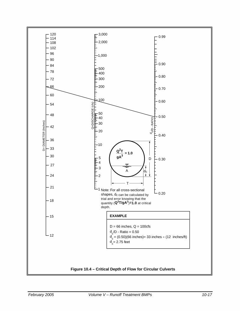
Figure 10.4 – Critical Depth of Flow for Circular Culverts
1200.99
0.90
0.80
0.70
0.60
0.50
0.40
0.30
0.20
3,000
2,000
1,000
500400
300
200
100
5040
30
20
10
54
3
2
1
114108
102
96
90
84
78
72
66
60
54
48
42
36
33
30
27
24
21
18
15
12
A
Note: For all cross-sectionalshapes, dc can be calculated by trial and error knowing that the quantity (Q2T/gA3)=1.0 at critical depth.
D = 66 inches, Q = 100cfsd
c/D - Ratio = 0.50d
c = (0.50)(66 inches)= 33 inches ÷ (12 inches/ft)d
c= 2.75 feet
D
T
dc
d c/D
- R
ATIO
Q=
DIS
CH
AR
GE
(cf
s)
D=
DIA
ME
TE
R (
Inch
es)
Q2T
gA3= 1.0
New Design ManualFigure 4.3.1.F Critical Depth of Flow for Circular CulvertsRevised 12-12-97mdev
EXAMPLE
February 2005 Volume V – Runoff Treatment BMPs 10-17

Figure 10.5 – Circular Channel Ratios
10-18 Volume V – Runoff Treatment BMPs February 2005

BMP T10.20 Wetvaults
Purpose and Definition A wetvault is an underground structure similar in appearance to a detention vault, except that a wetvault has a permanent pool of water (wetpool) which dissipates energy and improves the settling of particulate pollutants (see the wetvault details in Figure 10.6). Being underground, the wetvault lacks the biological pollutant removal mechanisms, such as algae uptake, present in surface wetponds.
Applications and Limitations A wetvault may be used for commercial, industrial, or roadway projects if there are space limitations precluding the use of other treatment BMPs. The use of wetvaults for residential development is highly discouraged. Combined detention and wetvaults are allowed; see BMP T10.40.
A wetvault is believed to be ineffective in removing dissolved pollutants such as soluble phosphorus or metals such as copper. There is also concern that oxygen levels will decline, especially in warm summer months, because of limited contact with air and wind. However, the extent to which this potential problem occurs has not been documented.
Below-ground structures like wetvaults are relatively difficult and expensive to maintain. The need for maintenance is often not seen and as a result routine maintenance does not occur.
If oil control is required for a project, a wetvault may be combined with an API oil/water separator.
Design Criteria
Sizing Procedure As with wetponds, the primary design factor that determines the removal efficiency of a wetvault is the volume of the wetpool. The larger the volume, the higher the potential for pollutant removal. Performance is also improved by avoiding dead zones (like corners) where little exchange occurs, using large length-to-width ratios, dissipating energy at the inlet, and ensuring that flow rates are uniform to the extent possible and not increased between cells.
The sizing procedure for a wetvault is identical to the sizing procedure for a wetpond. The wetpool volume for the wetvault shall be equal to or greater than the total volume of runoff from the 6-month, 24-hour storm event. Alternatively, the 91st percentile, 24-hour runoff volume estimated by an approved continuous runoff model may be used.
Typical design details and concepts for the wetvault are shown in Figure 10.6.
February 2005 Volume V – Runoff Treatment BMPs 10-19

���������������������
��������������������
yyyyyyyyyyyyyyyyyyyy
������������������yyyyyyyyyyyyyyyyyy
�����yyyyy����������yyyyyyyyyy�����yyyyy
������yyyyyy��yy�y
��yyladder
4’ min.7’ min.
WQ design WS
access doors or removable panel
average 1’ sediment storage(first cell)
average sediment storage1’ min. (first cell)
5% (min.) slope trowel finish
Access cover or doors required. See King County Road Standards forspecifications for manholes and ladders.
ventilation pipe (12” min.)
A
B
B
A“V” shapedbottom
OUTLETOpen pipe for wetvault only.
See detention vault forcombined water quality/
detention vault outlet
size to meet conveyancerequirements (Ch.1)
wetpool length
wetpool width
PLAN VIEWNTS
SECTION A-ANTS
frame, grate andlocking cover marked
“drain” (typ.)
inlet
first cell sized for25% to 35% of
wetpool volume
bottom slope 0.5-2%toward inlet end
detention optional
WQ design WS
wetpool depth
8’ max.1’ for WQ vaults 2’ for combined W.Q. and detention vaults
5’ x 10’ grate over second cell(may be provided by a grated 5’ x 10’ access door or panel)
gravity drain (if grade allows) placeas low as grade allows but must be 6” min. above the base elevation of vault walls or above sediment storage area
NOTE: capacity of outlet pipe designed to peak flowfor conveyance
3’ min.
2’ min.
1’
1’
bottom slope 0.5-2% towards outletend of second cell (recommended)
removable baffle
for vaults ≥ 1250 s.f. provide a 5’ x 10’ access door or removable panel over lowest portion of vault
ladder
SECTION B-BNTS
New Design ManualFigure 6.4.2.A WetvaultRevised 8-02-99, mdev
removablebaffle
Figure 10.6 – Wetvault
10-20 Volume V – Runoff Treatment BMPs February 2005

Wetpool Geometry
Same as specified for wetponds (see BMP T10.10) except for the following two modifications:
• The sediment storage in the first cell shall be an average of 1-foot. Because of the v-shaped bottom, the depth of sediment storage needed above the bottom of the side wall is roughly proportional to vault width according to the schedule below:
Vault Width
15' 20' 40' 60'
Sediment Depth (from bottom of side wall)
10" 9" 6" 4"
• The second cell shall be a minimum of 3 feet deep since planting cannot be used to prevent resuspension of sediment in shallow water as it can in open ponds.
Vault Structure
• The vault shall be separated into two cells by a wall or a removable baffle. If a wall is used, a 5-foot by 10-foot removable maintenance access must be provided for both cells. If a removable baffle is used, the following criteria apply:
1) The baffle shall extend from a minimum of 1-foot above the WQ design water surface to a minimum of 1-foot below the invert elevation of the inlet pipe.
2) The lowest point of the baffle shall be a minimum of 2 feet from the bottom of the vault, and greater if feasible.
• If the vault is less than 2,000 cubic feet (inside dimensions), or if the length-to-width ratio of the vault pool is 5:1 or greater, the baffle or wall may be omitted and the vault may be one-celled.
• The two cells of a wetvault should not be divided into additional subcells by internal walls. If internal structural support is needed, it is preferred that post and pier construction be used to support the vault lid rather than walls. Any walls used within cells must be positioned so as to lengthen, rather than divide, the flowpath.
Intent: Treatment effectiveness in wetpool facilities is related to the extent to which plug flow is achieved and short-circuiting and dead zones are avoided. Structural walls placed within the cells can interfere with plug flow and create significant dead zones, reducing treatment effectiveness.
February 2005 Volume V – Runoff Treatment BMPs 10-21
• The bottom of the first cell shall be sloped toward the access opening. Slope should be between 0.5 percent (minimum) and 2 percent (maximum). The second cell may be level (longitudinally) sloped toward the outlet, with a high point between the first and second cells. The intent of sloping the bottom is direct the sediment accumulation to the closest access point for maintenance purposes. Sloping the second cell towards the access opening for the first cell is also acceptable.
• The vault bottom shall slope laterally a minimum of 5 percent from each side towards the center, forming a broad "v" to facilitate sediment removal. Note: More than one "v" may be used to minimize vault depth.
Exception: The Local Plan Approval Authority may allow the vault bottom to be flat if removable panels are provided over the entire vault. Removable panels should be at grade, have stainless steel lifting eyes, and weigh no more than 5 tons per panel.
• The highest point of a vault bottom must be at least 6 inches below the outlet elevation to provide for sediment storage over the entire bottom.
• Provision for passage of flows should the outlet plug shall be provided.
• Wetvaults may be constructed using arch culvert sections provided the top area at the WQ design water surface is, at a minimum, equal to that of a vault with vertical walls designed with an average depth of 6 feet.
Intent: To prevent decreasing the surface area available for oxygen exchange.
• Wetvaults shall conform with the "Materials" and "Structural Stability" criteria specified for detention vaults in Volume III, Chapter 3.
• Where pipes enter and leave the vault below the WQ design water surface, they shall be sealed using a non-porous, non-shrinking grout.
Inlet and Outlet
• The inlet to the wetvault shall be submerged with the inlet pipe invert a minimum of 3 feet from the vault bottom. The top of the inlet pipe should be submerged at least 1-foot, if possible.
Intent: The submerged inlet is to dissipate energy of the incoming flow. The distance from the bottom is to minimize resuspension of settled sediments. Alternative inlet designs that accomplish these objectives are acceptable.
• Unless designed as an off-line facility, the capacity of the outlet pipe and available head above the outlet pipe should be designed to convey the 100-year design flow for developed site conditions without
10-22 Volume V – Runoff Treatment BMPs February 2005

overtopping the vault. The available head above the outlet pipe must be a minimum of 6 inches.
• The outlet pipe shall be back-sloped or have tee section, the lower arm of which should extend 1 foot below the WQ design water surface to provide for trapping of oils and floatables in the vault.
• The Local Plan Approval Authority may require a bypass/shutoff valve to enable the vault to be taken offline for maintenance.
Access Requirements
Same as for detention vaults (see Volume III, Section 3.2) except for the following additional requirement for wetvaults:
• A minimum of 50 square feet of grate should be provided over the second cell. For vaults in which the surface area of the second cell is greater than 1,250 square feet, 4 percent of the top should be grated. This requirement may be met by one grate or by many smaller grates distributed over the second cell area. Note: a grated access door can be used to meet this requirement.
Intent: The grate allows air contact with the wetpool in order to minimize stagnant conditions which can result in oxygen depletion, especially in warm weather.
Access Roads, Right of Way, and Setbacks
Same as for detention vaults (see Volume III, Section 3.2).
Recommended Design Features
The following design features should be incorporated into wetvaults where feasible, but they are not specifically required:
• The floor of the second cell should slope toward the outlet for ease of cleaning.
• The inlet and outlet should be at opposing corners of the vault to increase the flowpath.
• A flow length-to-width ratio greater than 3:1 minimum is desirable.
• Lockable grates instead of solid manhole covers are recommended to increase air contact with the wetpool.
• Galvanized materials shall not be used unless unavoidable.
• The number of inlets to the wetvault should be limited, and the flowpath length should be maximized from inlet to outlet for all inlets to the vault.
February 2005 Volume V – Runoff Treatment BMPs 10-23
Construction Criteria
Sediment that has accumulated in the vault must be removed after construction in the drainage area is complete. If no more than 12 inches of sediment have accumulated after the infrastructure is built, cleaning may be left until after building construction is complete. In general, sediment accumulation from stabilized drainage areas is not expected to exceed an average of 4 inches per year in the first cell. If sediment accumulation is greater than this amount, it will be assumed to be from construction unless it can be shown otherwise.
Operation and Maintenance
• Accumulated sediment and stagnant conditions may cause noxious gases to form and accumulate in the vault. Vault maintenance procedures must meet OSHA confined space entry requirements, which include clearly marking entrances to confined space areas. This may be accomplished by hanging a removable sign in the access riser(s), just under the access lid.
• Facilities should be inspected by the local government annually. The maintenance standards contained in Section 4.6 of this volume are measures for determining if maintenance actions are required as identified through the annual inspection.
• Sediment should be removed when the 1-foot sediment zone is full plus 6 inches. Sediments should be tested for toxicants in compliance with current disposal requirements. Sediments must be disposed in accordance with current local health department requirements and the Minimum Functional Standards for Solid Waste Handling. See Volume IV, Appendix IV-G Recommendations for Management of Street Waste for additional guidance.
• Any standing water removed during the maintenance operation must be properly disposed of. The preferred disposal option is discharge to a sanitary sewer at an approved location. Other disposal options include discharge back into the wetpool facility or the storm sewer system if certain conditions are met. See Volume IV, Appendix IV-G for additional guidance.
Modifications for Combining with a Baffle Oil/Water Separator If the project site is a high-use site and a wetvault is proposed, the vault may be combined with a baffle oil/water separator to meet the runoff treatment requirements with one facility rather than two. Structural modifications and added design criteria are given below. However, the maintenance requirements for baffle oil/water separators must be adhered to, in addition to those for a wetvault. This will result in more frequent inspection and cleaning than for a wetvault used only for TSS removal.
10-24 Volume V – Runoff Treatment BMPs February 2005

See Chapter 11 for information on maintenance of baffle oil/water separators.
1. The sizing procedures for the baffle oil/water separator (Chapter 11) should be run as a check to ensure the vault is large enough. If the oil/water separator sizing procedures result in a larger vault size, increase the wetvault size to match.
2. An oil retaining baffle shall be provided in the second cell near the vault outlet. The baffle should not contain a high-flow overflow, or else the retained oil will be washed out of the vault during large storms.
3. The vault shall have a minimum length-to-width ratio of 5:1.
4. The vault shall have a design water depth-to-width ratio of between 1:3 to 1:2.
5. The vault shall be watertight and shall be coated to protect from corrosion.
6. Separator vaults shall have a shutoff mechanism on the outlet pipe to prevent oil discharges during maintenance and to provide emergency shut-off capability in case of a spill. A valve box and riser shall also be provided.
7. Wetvaults used as oil/water separators must be off-line and must bypass flows greater than the off-line WQ design flow multiplied by the off-line ratio indicated in Figure 9.5b.
Intent: This design minimizes the entrainment and/or emulsification of previously captured oil during very high flow events.
February 2005 Volume V – Runoff Treatment BMPs 10-25

BMP T10.30 Stormwater Treatment Wetlands
Purpose and Definition In land development situations, wetlands are usually constructed for two main reasons: to replace or mitigate impacts when natural wetlands are filled or impacted by development (mitigation wetlands), and to treat stormwater runoff (stormwater treatment wetlands). Stormwater treatment wetlands are shallow man-made ponds that are designed to treat stormwater through the biological processes associated with emergent aquatic plants (see the stormwater wetland details in Figure 10.7 and Figure 10.8.
Wetlands created to mitigate disturbance impacts, such as filling, may not also be used as stormwater treatment facilities. This is because of the different, incompatible functions of the two kinds of wetlands. Mitigation wetlands are intended to function as full replacement habitat for fish and wildlife, providing the same functions and harboring the same species diversity and biotic richness as the wetlands they replace. Stormwater treatment wetlands are used to capture and transform pollutants, just as wetponds are, and over time pollutants will concentrate in the sediment. This is not a healthy environment for aquatic life. Stormwater treatment wetlands are used to capture pollutants in a managed environment so that they will not reach natural wetlands and other ecologically important habitats. In addition, vegetation must occasionally be harvested and sediment dredged in stormwater treatment wetlands, further interfering with use for wildlife habitat.
In general, stormwater wetlands perform well to remove sediment, metals, and pollutants that bind to humic or organic acids. Phosphorus removal in stormwater wetlands is highly variable.
Applications and Limitations
This stormwater wetland design occupies about the same surface area as wetponds, but has the potential to be better integrated aesthetically into a site because of the abundance of emergent aquatic vegetation. The most critical factor for a successful design is the provision of an adequate supply of water for most of the year. Careful planning is needed to be sure sufficient water will be retained to sustain good wetland plant growth. Since water depths are shallower than in wetponds, water loss by evaporation is an important concern. Stormwater wetlands are a good WQ facility choice in areas with high winter groundwater levels.
10-26 Volume V – Runoff Treatment BMPs February 2005

Design Criteria When used for stormwater treatment, stormwater wetlands employ some of the same design features as wetponds. However, instead of gravity settling being the dominant treatment process, pollutant removal mediated by aquatic vegetation and the microbiological community associated with that vegetation becomes the dominant treatment process. Thus when designing wetlands, water volume is not the dominant design criteria. Rather, factors which affect plant vigor and biomass are the primary concerns.
Sizing Procedure
Step 1: The volume of a basic wetpond is used as a template for sizing the stormwater wetland. The design volume is the total volume of runoff from the 6-month, 24-hour storm event. Alternatively, the 91st percentile, 24-hour runoff volume estimated by an approved continuous runoff model may be used.
Step 2: Calculate the surface area of the stormwater wetland. The surface area of the wetland shall be the same as the top area of a wetpond sized for the same site conditions. Calculate the surface area of the stormwater wetland by using the volume from Step 1 and dividing by the average water depth (use 3 feet).
Step 3: Determine the surface area of the first cell of the stormwater wetland. Use the volume determined from Criterion 2 under "Wetland Geometry", and the actual depth of the first cell.
Step 4: Determine the surface area of the wetland cell. Subtract the surface area of the first cell (Step 3) from the total surface area (Step 2).
Step 5: Determine water depth distribution in the second cell. Decide if the top of the dividing berm will be at the surface or submerged (designer's choice). Adjust the distribution of water depths in the second cell according to Criterion 8 under "Wetland Geometry" below. Note: This will result in a facility that holds less volume than that determined in Step 1 above. This is acceptable.
Intent: The surface area of the stormwater wetland is set to be roughly equivalent to that of a wetpond designed for the same site so as not to discourage use of this option.
Step 6: Choose plants. See Table 10.1 for a list of plants recommended for wetpond water depth zones, or consult a wetland scientist.
February 2005 Volume V – Runoff Treatment BMPs 10-27
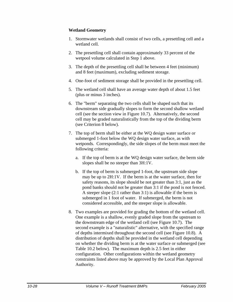
Wetland Geometry
1. Stormwater wetlands shall consist of two cells, a presettling cell and a wetland cell.
2. The presettling cell shall contain approximately 33 percent of the wetpool volume calculated in Step 1 above.
3. The depth of the presettling cell shall be between 4 feet (minimum) and 8 feet (maximum), excluding sediment storage.
4. One-foot of sediment storage shall be provided in the presettling cell.
5. The wetland cell shall have an average water depth of about 1.5 feet (plus or minus 3 inches).
6. The "berm" separating the two cells shall be shaped such that its downstream side gradually slopes to form the second shallow wetland cell (see the section view in Figure 10.7). Alternatively, the second cell may be graded naturalistically from the top of the dividing berm (see Criterion 8 below).
7. The top of berm shall be either at the WQ design water surface or submerged 1-foot below the WQ design water surface, as with wetponds. Correspondingly, the side slopes of the berm must meet the following criteria:
a. If the top of berm is at the WQ design water surface, the berm side slopes shall be no steeper than 3H:1V.
b. If the top of berm is submerged 1-foot, the upstream side slope may be up to 2H:1V. If the berm is at the water surface, then for safety reasons, its slope should be not greater than 3:1, just as the pond banks should not be greater than 3:1 if the pond is not fenced. A steeper slope (2:1 rather than 3:1) is allowable if the berm is submerged in 1 foot of water. If submerged, the berm is not considered accessible, and the steeper slope is allowable.
8. Two examples are provided for grading the bottom of the wetland cell. One example is a shallow, evenly graded slope from the upstream to the downstream edge of the wetland cell (see Figure 10.7). The second example is a "naturalistic" alternative, with the specified range of depths intermixed throughout the second cell (see Figure 10.8). A distribution of depths shall be provided in the wetland cell depending on whether the dividing berm is at the water surface or submerged (see Table 10.2 below). The maximum depth is 2.5 feet in either configuration. Other configurations within the wetland geometry constraints listed above may be approved by the Local Plan Approval Authority.
10-28 Volume V – Runoff Treatment BMPs February 2005
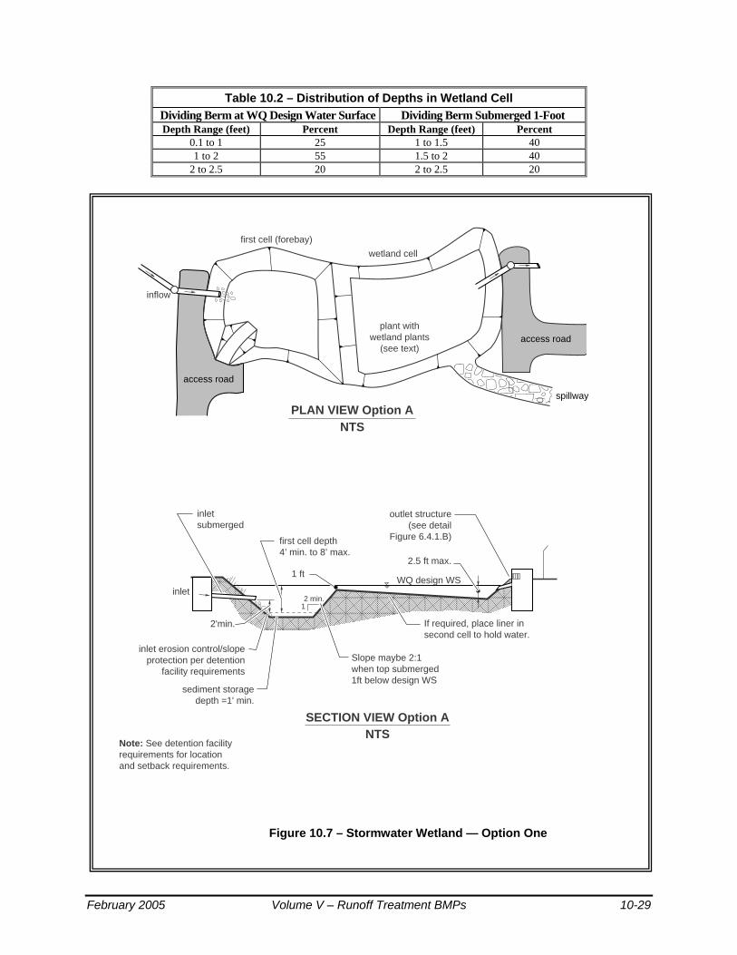
Table 10.2 – Distribution of Depths in Wetland Cell Dividing Berm at WQ Design Water Surface Dividing Berm Submerged 1-Foot Depth Range (feet) Percent Depth Range (feet) Percent
0.1 to 1 25 1 to 1.5 40 1 to 2 55 1.5 to 2 40
2 to 2.5 20 2 to 2.5 20
Figure 10.7 – Stormwater Wetland — Option One
����������������������������������������������������������������������������������������������������
����
����
WQ design WS
sediment storagedepth =1' min.
2 min.
outlet structure(see detail
Figure 6.4.1.B)
inlet erosion control/slope protection per detention
facility requirements
first cell depth 4’ min. to 8’ max.
Note: See detention facilityrequirements for locationand setback requirements.
1 ft
inlet
PLAN VIEW Option ANTS
inletsubmerged
Slope maybe 2:1when top submerged1ft below design WS
2.5 ft max.
If required, place liner in second cell to hold water.
2'min.
1
first cell (forebay)
wetland cell
plant withwetland plants
(see text)
SECTION VIEW Option ANTS
New Design ManualFigure 6.4.3.A Constructed Wetland - Option ARevised 4-30-97, mdev
inflow
spillway
access road
access road
February 2005 Volume V – Runoff Treatment BMPs 10-29
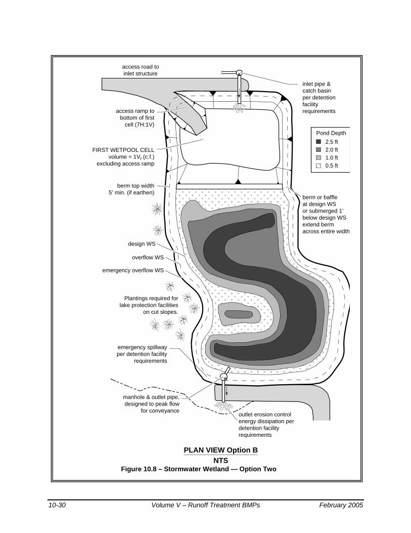
Figure 10.8 – Stormwater Wetland — Option Two
����������������������������������������������������������������������������������������������������������������������������������������������������������������������������������������������������������������
yyyyyyyyyyyyyyyyyyyyyyyyyyyyyyyyyyyyyyyyyyyyyyyyyyyyyyyyyyyyyyyyyyyyyyyyyyyyyyyyyyyyyyyyyyyyyyyyyyyyyyyyyyyyyyyyyyyyyyyyyyyyyyyyyyyyyyyyyyyyyyyyyyyyyyyyyyyyyyyyyyyyyyyyyyyyyyyyyyyyyyyyyyyyyyyyyyyyyyyyyyyyyyyy
Plantings required for lake protection facilities
on cut slopes.
emergency spillwayper detention facility
requirements
FIRST WETPOOL CELLvolume = 1Vr (c.f.)
excluding access ramp
berm top width5’ min. (if earthen)
access ramp tobottom of first
cell (7H:1V)
berm or baffleat design WSor submerged 1’below design WSextend bermacross entire width
outlet erosion controlenergy dissipation perdetention facilityrequirements
manhole & outlet pipe,designed to peak flow
for conveyance
inlet pipe &catch basinper detentionfacilityrequirements
PLAN VIEW Option BNTS
access road toinlet structure
�y
2.5 ft2.0 ft1.0 ft0.5 ft
Pond Depth
design WS
New Design ManualFigure 6.4.3.B Constructed Wetland Op BRevised 4-30-97, mdev
emergency overflow WS
overflow WS
10-30 Volume V – Runoff Treatment BMPs February 2005

Lining Requirements In infiltrative soils, both cells of the stormwater wetland shall be lined. To determine whether a low-permeability liner or a treatment liner is required, determine whether the following conditions will be met. If soil permeability will allow sufficient water retention, lining may be waived.
1 The second cell must retain water for at least 10 months of the year. 2. The first cell must retain at least three feet of water year-round. 3. A complete precipitation record shall be used when establishing these conditions. Evapotranspiration losses shall be taken into account as well as infiltration losses.
Intent: Many wetland plants can adapt to periods of summer drought, so a limited drought period is allowed in the second cell. This may allow a treatment liner rather than a low permeability liner to be used for the second cell. The first cell must retain water year-round in order for the presettling function to be effective.
• If a low permeability liner is used, a minimum of 18 inches of native soil amended with good topsoil or compost (one part compost mixed with 3 parts native soil) must be placed over the liner. For geomembrane liners, a soil depth of 3 feet is recommended to prevent damage to the liner during planting. Hydric soils are not required.
The criteria for liners given in Chapter 4 must be observed.
Inlet and Outlet
Same as for wetponds (see BMP T10.10).
Access and Setbacks
• Location of the stormwater wetland relative to site constraints (e.g., buildings, property lines, etc.) shall be the same as for detention ponds (see Volume III). See Chapter 4 for typical setback requirements for WQ facilities.
• Access and maintenance roads shall be provided and designed according to the requirements for detention ponds (see Volume III). Access and maintenance roads shall extend to both the wetland inlet and outlet structures. An access ramp (7H minimum:1V) shall be provided to the bottom of the first cell unless all portions of the cell can be reached and sediment loaded from the top of the wetland side slopes.
• If the dividing berm is also used for access, it should be built to sustain loads of up to 80,000 pounds.
February 2005 Volume V – Runoff Treatment BMPs 10-31

Planting Requirements
The wetland cell shall be planted with emergent wetland plants following the recommendations given in Table 10.1 or the recommendations of a wetland specialist. Note: Cattails (Typha latifolia) are not recommended. They tend to escape to natural wetlands and crowd out other species. In addition, the shoots die back each fall and will result in oxygen depletion in the wetpool unless they are removed.
Construction Criteria
• Construction and maintenance considerations are the same as for wetponds.
• Construction of the naturalistic alternative (Option 2) can be easily done by first excavating the entire area to the 1.5-foot average depth. Then soil subsequently excavated to form deeper areas can be deposited to raise other areas until the distribution of depths indicated in the design is achieved.
Operation and Maintenance
• Wetlands should be inspected at least twice per year during the first three years during both growing and non-growing seasons to observe plant species presence, abundance, and condition; bottom contours and water depths relative to plans; and sediment, outlet, and buffer conditions.
• Maintenance should be scheduled around sensitive wildlife and vegetation seasons.
• Plants may require watering, physical support, mulching, weed removal, or replanting during the first three years.
• Nuisance plant species should be removed and desirable species should be replanted.
• The effectiveness of harvesting for nutrient control is not well documented. There are many drawbacks to harvesting, including possible damage to the wetlands and the inability to remove nutrients in the below-ground biomass. If harvesting is practiced, it should be done in the late summer.
10-32 Volume V – Runoff Treatment BMPs February 2005

Resource Material
King County Surface Water Design Manual, September 1998.
Schueler, Thomas. Design of Stormwater Wetland Systems, Guidelines for Creating Diverse and Effective Stormwater Wetland Systems in the Mid-Atlantic Region, October, 1992.
Kadlec, Robert and Robert L. Knight. Treatment Wetlands. 1996.
February 2005 Volume V – Runoff Treatment BMPs 10-33
BMP T10.40 Combined Detention and Wetpool Facilities
Purpose and Definition
Combined detention and WQ wetpool facilities have the appearance of a detention facility but contain a permanent pool of water as well. The following design procedures, requirements, and recommendations cover differences in the design of the stand-alone WQ facility when combined with detention storage. The following combined facilities are addressed:
• Detention/wetpond (basic and large) • Detention/wetvault • Detention/stormwater wetland.
There are two sizes of the combined wetpond, a basic and a large, but only a basic size for the combined wetvault and combined stormwater wetland. The facility sizes (basic and large) are related to the pollutant removal goals. See Chapter 3 for more information about treatment performance goals.
Applications and Limitations
Combined detention and water quality facilities are very efficient for sites that also have detention requirements. The water quality facility may often be placed beneath the detention facility without increasing the facility surface area. However, the fluctuating water surface of the live storage will create unique challenges for plant growth and for aesthetics alike.
The basis for pollutant removal in combined facilities is the same as in the stand-alone WQ facilities. However, in the combined facility, the detention function creates fluctuating water levels and added turbulence. For simplicity, the positive effect of the extra live storage volume and the negative effect of increased turbulence are assumed to balance, and are thus ignored when sizing the wetpool volume. For the combined detention/stormwater wetland, criteria that limit the extent of water level fluctuation are specified to better ensure survival of the wetland plants.
Unlike the wetpool volume, the live storage component of the facility should be provided above the seasonal high water table.
Combined Detention and Wetpond (Basic and Large) Typical design details and concepts for a combined detention and wetpond are shown in Figures 10.9 and 10.10. The detention portion of the facility shall meet the design criteria and sizing procedures set forth in Volume 3.
10-34 Volume V – Runoff Treatment BMPs February 2005

Sizing Procedure The sizing procedure for combined detention and wetponds are identical to those outlined for wetponds and for detention facilities. The wetpool volume for a combined facility shall be equal to or greater than the total volume of runoff from the 6-month, 24-hour storm event. Alternatively, the 91st percentile, 24-hour runoff volume estimated by an approved continuous runoff model may be used to size the wetpool. Follow the standard procedure specified in Volume III to size the detention portion of the pond.
Detention and Wetpool Geometry
• The wetpool and sediment storage volumes shall not be included in the required detention volume.
• The "Wetpool Geometry" criteria for wetponds (see BMP T10.10) shall apply with the following modifications/clarifications:
Criterion 1: The permanent pool may be made shallower to take up most of the pond bottom, or deeper and positioned to take up only a limited portion of the bottom. Note, however, that having the first wetpool cell at the inlet allows for more efficient sediment management than if the cell is moved away from the inlet. Wetpond criteria governing water depth must, however, still be met. See Figure 10.11 for two possibilities for wetpool cell placement.
Intent: This flexibility in positioning cells is provided to allow for multiple use options, such as volleyball courts in live storage areas in the drier months.
Criterion 2: The minimum sediment storage depth in the first cell is 1-foot. The 6 inches of sediment storage required for detention ponds does not need to be added to this, but 6 inches of sediment storage must be added to the second cell to comply with the detention sediment storage requirement.
Berms, Baffles, and Slopes Same as for wetponds (see BMP T10.10).
February 2005 Volume V – Runoff Treatment BMPs 10-35
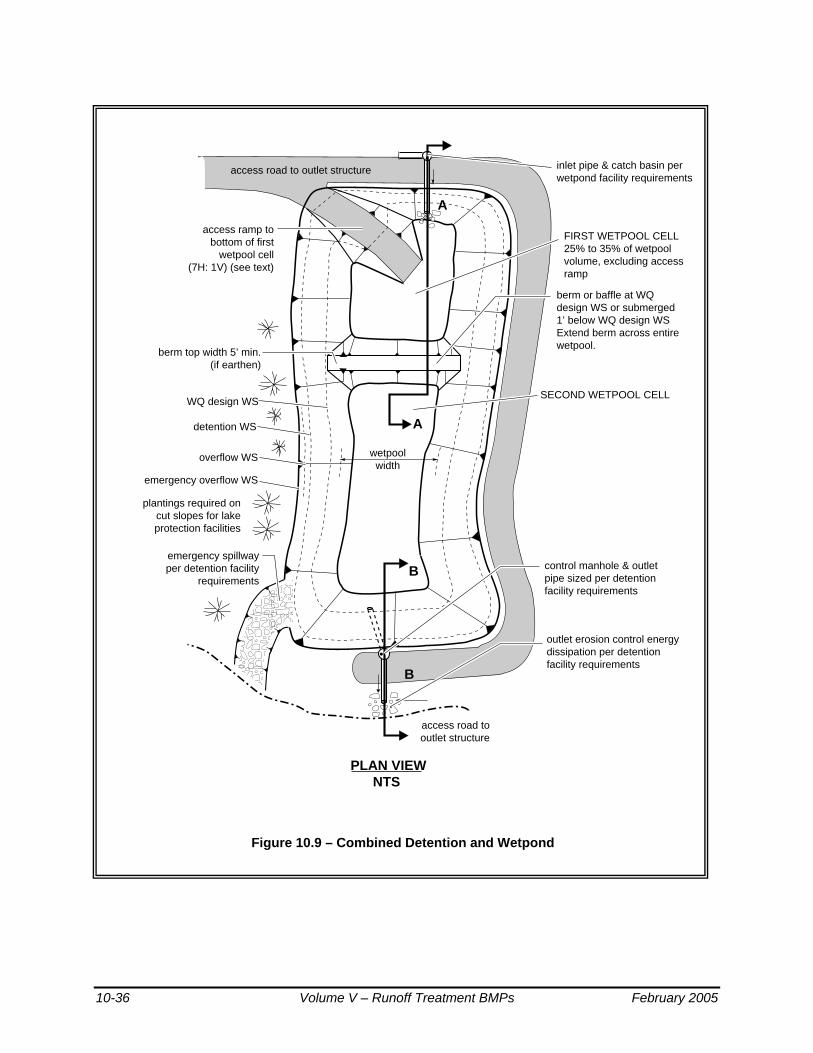
Figure 10.9 – Combined Detention and Wetpond
������
berm or baffle at WQ design WS or submerged 1’ below WQ design WS Extend berm across entirewetpool.
plantings required on cut slopes for lake protection facilities
emergency spillway per detention facility
requirements
FIRST WETPOOL CELL25% to 35% of wetpool volume, excluding access ramp
access ramp to bottom of first
wetpool cell (7H: 1V) (see text)
SECOND WETPOOL CELL
emergency overflow WS
overflow WS wetpoolwidth
PLAN VIEWNTS
inlet pipe & catch basin perwetpond facility requirements
outlet erosion control energy dissipation per detention facility requirements
control manhole & outlet pipe sized per detention facility requirements
A
A
B
B
berm top width 5’ min. (if earthen)
access road to outlet structure
access road to outlet structure
detention WS
WQ design WS
New Design ManualFigure 6.4.4.A Combined Detention and WetpondRevised 4-30-97, mdev
10-36 Volume V – Runoff Treatment BMPs February 2005

Figure 10.10 – Combined Detention and Wetpond (Continued)
��������������������������������������������������������������������������������
yyyyyyyyyyyyyyyyyyyyyyyyyyyyyyyyyyyyyyyyyyyyyyyyyyyyyyyyyyyyyyyyyyyyyyyyyyyyyyyy
���������������������
yyyyyyyyyyyyyyyyyyyyy
������������������������������������
yyyyyyyyyyyyyyyyyyyyyyyyyyyyyyyyyyyy
��������������yyyyyyyyyyyyyy
Note: See detention facility requirements for location, interior & exterior sideslopes, and setback requirements.
Invert 6” min. below top of internal
berm. Lower placement
is desirable.
emergency overflow WS
gravity drain(if grade allows) 8” min. diameter
18” min.
exterior berms designed perdam safety requirementsif applicable
capacity of outlet system per detention facilityrequirements
fence required for interior side slopes steeper than 3(H) :1(V)
WQ design WS
type 2catch basinw/sump
outlet pipe invert out at wetpool WS elevation access road
valve
SECTION B-BNTS
sediment storagedepth = 1’ min.
slope vegetationper detention
facility requirements
access roadper detention
facility requirements
detentionper detentionfacility requirements
inlet erosion control/slope protection per
detention facilityrequirements
first celldepth 4’ min.to 8’ max.
wetpool depth 8’ max. Recirculation recommended for depth > 6’.
Emergent vegetationrequired for wetpooldepths 3’ or less.
Note: Berm slope maybe 2:1 when top of berm submerged 1’ below WQ design W.S.
2’ min.
keyed
emergency overflow WS
submerged inlet
wetpool flow length = 3 x width (min.)
SECTION A-ANTS
1ft
detention design WS
WQ design WS
detention overflow WS
detention overflow WSdetention design WS
New Design ManualFigure 6.4.4.A.X Combined Detention and Wetpond (Continued)Revised 7-29-99, mdev
31
Top of berm or baffle level and at wetpool design elevation (flow exits first cell over berm) or as noted.
February 2005 Volume V – Runoff Treatment BMPs 10-37

Figure 10.11 – Alternative Configurations of Detention and Wetpool Areas
������������������������������
������������
������������
������������ ����
����
������
�������������������������������������������������������
��������������
������������������
inlet
detention pond overflow WS
additional detentionpond storage area
WQ design WS
sediment storage
wetpool length =L1 + L2
control manhole
valve
gravity drain (if grade allows)
shelf usable
in summer
L1 L2
SECTION VIEWNTS
inlet
detention pondoverflow WS
WQ design WS
sediment storage
control manhole
gate valve
gravity drain (If grade allows)
keyed berm
detentionstorage
shelf usable in summer
SECTION VIEWNTS
Note: These examples show how the combined detention/wetpool can be configured to allow for “shelves” for joint use opportunities in dry weather.Other options may also be acceptable.
New Design ManualFigure 6.4.4.B Alternative Configuration of Detention and Wetpool AreasRevised 6-17-97, wgab
10-38 Volume V – Runoff Treatment BMPs February 2005

Inlet and Outlet The "Inlet and Outlet" criteria for wetponds shall apply with the following modifications:
• A sump must be provided in the outlet structure of combined ponds. • The detention flow restrictor and its outlet pipe shall be designed
according to the requirements for detention ponds (see Volume III).
Access and Setbacks Same as for wetponds.
Planting Requirements Same as for wetponds.
Combined Detention and Wetvault The sizing procedure for combined detention and wetvaults is identical to those outlined for wetvaults and for detention facilities. The wetvault volume for a combined facility shall be equal to or greater than the total volume of runoff from the 6-month, 24-hour storm event. Alternatively, the 91st percentile, 24-hour runoff volume estimated by an approved continuous runoff model may be used to size the wetpool portion of vault. Follow the standard procedure specified in Volume 3 to size the detention portion of the vault.
The design criteria for detention vaults and wetvaults must both be met, except for the following modifications or clarifications:
• The minimum sediment storage depth in the first cell shall average 1-foot. The 6 inches of sediment storage required for detention vaults does not need to be added to this, but 6 inches of sediment storage must be added to the second cell to comply with detention vault sediment storage requirements.
• The oil retaining baffle shall extend a minimum of 2 feet below the WQ design water surface.
Intent: The greater depth of the baffle in relation to the WQ design water surface compensates for the greater water level fluctuations experienced in the combined vault. The greater depth is deemed prudent to better ensure that separated oils remain within the vault, even during storm events.
Note: If a vault is used for detention as well as water quality control, the facility may not be modified to function as a baffle oil/water separator as allowed for wetvaults in BMP T10.20. This is because the added pool fluctuation in the combined vault does not allow for the quiescent conditions needed for oil separation.
Combined Detention and Stormwater Wetland The sizing procedure for combined detention and stormwater wetlands is identical to those outlined for stormwater wetlands and for detention facilities. Follow the procedure specified in BMP T10.30 to determine the
February 2005 Volume V – Runoff Treatment BMPs 10-39

stormwater wetland size. Follow the standard procedure specified in Volume III to size the detention portion of the wetland. The design criteria for detention ponds and stormwater wetlands must both be met, except for the following modifications or clarifications: • The "Wetland Geometry" criteria for stormwater wetlands (see BMP
T10.30) are modified as follows: • The minimum sediment storage depth in the first cell is 1-foot. The 6
inches of sediment storage required for detention ponds does not need to be added to this, nor does the 6 inches of sediment storage in the second cell of detention ponds need to be added.
Intent: Since emergent plants are limited to shallower water depths, the deeper water created before sediments accumulate is considered detrimental to robust emergent growth. Therefore, sediment storage is confined to the first cell which functions as a presettling cell. The "Inlet and Outlet" criteria for wetponds shall apply with the following modifications: • A sump must be provided in the outlet structure of combined facilities. • The detention flow restrictor and its outlet pipe shall be designed
according to the requirements for detention ponds (see Volume III). The "Planting Requirements" for stormwater wetlands are modified to use the following plants which are better adapted to water level fluctuations:
Scirpus acutus (hardstem bulrush) 2 - 6' depth Scirpus microcarpus (small-fruited bulrush) 1 - 2.5' depth Sparganium emersum (burreed) 1 - 2' depth Sparganium eurycarpum (burreed) 1 - 2' depth Veronica sp. (marsh speedwell) 0 - 1' depth
In addition, the shrub Spirea douglasii (Douglas spirea) may be used in combined facilities. Water Level Fluctuation Restrictions: The difference between the WQ design water surface and the maximum water surface associated with the 2-year runoff shall not be greater than 3 feet. If this restriction cannot be met, the size of the stormwater wetland must be increased. The additional area may be placed in the first cell, second cell, or both. If placed in the second cell, the additional area need not be planted with wetland vegetation or counted in calculating the average depth.
Intent: This criterion is designed to dampen the most extreme water level fluctuations expected in combined facilities to better ensure that fluctuation-tolerant wetland plants will be able to survive in the facility. It is not intended to protect native wetland plant communities and is not to be applied to natural wetlands.
10-40 Volume V – Runoff Treatment BMPs February 2005
Chapter 11 - Oil and Water Separators This chapter provides a discussion of oil and water separators, including their application and design criteria. BMPs are described for baffle type and coalescing plate separators.
11.1 Purpose of Oil and Water Separators
To remove oil and other water-insoluble hydrocarbons, and settleable solids from stormwater runoff.
11.2 Description
Oil and water separators are typically the American Petroleum Institute (API) (also called baffle type) (American Petroleum Institute, 1990) or the coalescing plate (CP) type using a gravity mechanism for separation. See Figures 11.1 and 11.2. Oil removal separators typically consist of three bays; forebay, separator section, and the afterbay. The CP separators need considerably less space for separation of the floating oil due to the shorter travel distances between parallel plates. A spill control (SC) separator (Figure 11.3) is a simple catchbasin with a T-inlet for temporarily trapping small volumes of oil. The spill control separator is included here for comparison only and is not designed for, or to be used for treatment purposes.
February 2005 Volume V – Runoff Treatment BMPs 11-1

Figure 11.1 – API (Baffle Type) Separator
Source: King County (reproduced with permission)
11-2 Volume V – Runoff Treatment BMPs February 2005
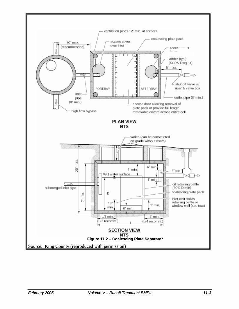
Figure 11.2 – Coalescing Plate Separator Figure 11.2 – Coalescing Plate Separator
Source: King County (reproduced with permission) Source: King County (reproduced with permission)
February 2005 Volume V – Runoff Treatment BMPs 11-3 February 2005 Volume V – Runoff Treatment BMPs 11-3

Figure 11.3 – Spill Control Separator (not for oil treatment)
Source: 1992 Ecology Manual
11-4 Volume V – Runoff Treatment BMPs February 2005

11.3 Performance Objectives Oil and water separators should be designed to remove oil and TPH down to 15 mg/L at any time and 10 mg/L on a 24-hr average, and produce a discharge that does not cause an ongoing or recurring visible sheen in the stormwater discharge, or in the receiving water. (See also Chapter 3)
11.4 Applications/Limitations
The following are potential applications of oil and water separators where free oil is expected to be present at treatable high concentrations and sediment will not overwhelm the separator. (Seattle METRO, 1990; Watershed Protection Techniques, 1994; King County Surface Water Management, 1998) For low concentrations of oil, other treatments may be more applicable. These include sand filters and emerging technologies.
• Commercial and industrial areas including petroleum storage yards, vehicle maintenance facilities, manufacturing areas, airports, utility areas (water, electric, gas), and fueling stations.(King County Surface Water Management, 1998)
• Facilities that would require oil control BMPs under the high-use site threshold described in Chapter 2 including parking lots at convenience stores, fast food restaurants, grocery stores, shopping malls, discount warehouse stores, banks, truck fleets, auto and truck dealerships, and delivery services. (King County Surface Water Management, 1998)
• Without intense maintenance oil/water separators may not be sufficiently effective in achieving oil and TPH removal down to required levels.
• Pretreatment should be considered if the level of TSS in the inlet flow would cause clogging or otherwise impair the long-term efficiency of the separator.
• For inflows from small drainage areas (fueling stations, maintenance shops, etc.) a coalescing plate (CP) type separator is typically considered, due to space limitations. However, if plugging of the plates is likely, then a new design basis for the baffle type API separator may be considered on an experimental basis. (See 11.6 Design Criteria)
February 2005 Volume V – Runoff Treatment BMPs 11-5

11.5 Site Suitability
Consider the following site characteristics:
• Sufficient land area • Adequate TSS control or pretreatment capability • Compliance with environmental objectives • Adequate influent flow attenuation and/or bypass capability • Sufficient access for operation and maintenance (O & M)
11.6 Design Criteria-General Considerations
There is concern that oil/water separators used for stormwater treatment have not performed to expectations.(Watershed Protection Techniques, 1994; Schueler, Thomas R., 1990) Therefore, emphasis should be given to proper application (see Section 11.4), design, O & M, (particularly sludge and oil removal) and prevention of CP fouling and plugging.(US Army of Engineers, 1994) Other treatment systems, such as sand filters and emerging technologies, should be considered for the removal of insoluble oil and TPH.
The following are design criteria applicable to API and CP oil/water separators:
• If practicable, determine oil/grease (or TPH) and TSS concentrations, lowest temperature, pH; and empirical oil rise rates in the runoff, and the viscosity, and specific gravity of the oil. Also determine whether the oil is emulsified or dissolved. (Washington State Department of Ecology, 1995) Do not use oil/water separators for the removal of dissolved or emulsified oils such as coolants, soluble lubricants, glycols, and alcohols.
• Locate the separator off-line and bypass the incremental portion of flows that exceed the off-line 15-minute, Water Quality design flow rate multiplied by the ratio indicated in Figure 9.5b of this Volume. If it is necessary to locate the separator on-line, try to minimize the size of the area needing oil control, and use the on-line water quality design flow rate multiplied by the ratio indicated in Figure 9.5a.
• Use only impervious conveyances for oil contaminated stormwater.
• Specify appropriate performance tests after installation and shakedown, and/or certification by a professional engineer that the separator is functioning in accordance with design objectives. Expeditious corrective actions must be taken if it is determined the separator is not achieving acceptable performance levels.
11-6 Volume V – Runoff Treatment BMPs February 2005

• Add pretreatment for TSS that could cause clogging of the CP separator, or otherwise impair the long-term effectiveness of the separator.
Criteria for Separator Bays:
• Size the separator bay for the Water Quality design flow rate (15 minute time step) x a correction factor ratio indicated in Figure 9.5b of this Volume (assuming an off-line facility). (See Chapter 4 of this Volume for a definition of the Water Quality Design Flow Rate.)
• To collect floatables and settleable solids, design the surface area of the forebay at ≥ 20 ft² per 10,000 ft² of area draining to the separator (6). The length of the forebay should be 1/3-1/2 of the length of the entire separator. Include roughing screens for the forebay or upstream of the separator to remove debris, if needed. Screen openings should be about 3/4 inch.
• Include a submerged inlet pipe with a turn-down elbow in the first bay at least two feet from the bottom. The outlet pipe should be a Tee, sized to pass the design peak flow and placed at least 12 inches below the water surface.
• Include a shutoff mechanism at the separator outlet pipe. (King County Surface Water Management, 1998)
• Use absorbents and/or skimmers in the afterbay as needed.
Criteria for Baffles: • Oil retaining baffles (top baffles) should be located at least at 1/4 of
the total separator length from the outlet and should extend down at least 50% of the water depth and at least 1 ft. from the separator bottom.
• Baffle height to water depth ratios should be 0.85 for top baffles and 0.15 for bottom baffles.
11.7 Oil and Water Separator BMPs
Two BMPs are described in this section. BMP T11.10 for baffle type separators, and BMP T11.11 for coalescing plate separators.
February 2005 Volume V – Runoff Treatment BMPs 11-7

BMP T11.10 API (Baffle type) Separator Bay Design Criteria The criteria for small drainages is based on Vh, Vt, residence time, width, depth, and length considerations. As a correction factor API's turbulence criteria is applied to increase the length.
Ecology is modifying the API criteria for treating stormwater runoff from small drainage area (fueling stations, commercial parking lots, etc.) by using the design hydraulic horizontal velocity, Vh, for the design Vh/Vt ratio rather than the API minimum of Vh/Vt = 15. The API criteria appear applicable for greater than two acres of impervious drainage area. Performance verification of this design basis must be obtained during at least one wet season using the test protocol referenced in Chapter 12 for new technologies.
The following is the sizing procedure using modified API criteria:
• Determine the oil rise rate, Vt, in cm/sec, using Stokes Law (Water Pollution Control Federation, 1985), or empirical determination, or 0.033 ft./min for 60µ oil. The application of Stokes’ Law to site-based oil droplet sizes and densities, or empirical rise rate determinations recognizes the need to consider actual site conditions. In those cases the design basis would not be the 60 micron droplet size and the 0.033 ft/min. rise rate.
• Stokes Law equation for rise rate, Vt (cm/sec):
Vt = g(σw-σo)D² /18ηw)
Where:
g = gravitational constant (981 cm/sec²) D = diameter of the oil particle in cm.
Use
oil particle size diameter, D=60 microns (0.006 cm) σw =0.999 gm/cc. at 32° F σo: Select conservatively high oil density,
For example, if diesel oil @ σo=0.85 gm/cc and motor oil @ σo = 0.90 can be present then use σo=0.90 gm/cc ηw = 0.017921 poise, gm/cm-sec. at Tw=32 °F, (See API Publication 421, February , 1990) Use the following separator dimension criteria:
Separator water depth, d ≥3≤8 feet (to minimize turbulence) (American Petroleum Institute, 1990; US Army Corps of Engineers, 1994).
11-8 Volume V – Runoff Treatment BMPs February 2005

Separator width, 6-20 feet (WEF & ASCE, 1998; King County Surface Water Management, 1998) Depth/width (d/w) of 0.3-0.5 (American Petroleum Institute, 1990)
For Stormwater Inflow from Drainages under 2 Acres:
1. Determine Vt and select depth and width of the separator section based on above criteria.
2. Calculate the minimum residence time (tm) of the separator at depth d:
tm = d/Vt
3. Calculate the horizontal velocity of the bulk fluid, Vh, vertical cross-sectional area, Av, and actual design Vh/Vt (American Petroleum Institute, 1990; US Army Corps of Engineers, 1994).
Vh = Q/dw = Q/Av (Vh maximum at < 2.0 ft/min.)(American Petroleum Institute, 1990)
Q = (k) the ratio indicated in Figure 9.5b for the site location multiplied by he 15-minute Water Quality design flow rate in ft³/min, at minimum residence time, tm
At Vh/Vt determine F, turbulence and short-circuiting factor (Appendix V-D) API F factors range from 1.28-1.74. (American Petroleum Institute, 1990)
4. Calculate the minimum length of the separator section, l(s), using:
l(s) = FQtm/wd = F(Vh/Vt)d l(t) = l(f) + l(s) +l(a) l(t) = l(t)/3 + l(s) + l(t)/4
Where:
l(t) = total length of 3 bays = “L” in Figure 11.1 l(f) = length of forebay l(a) = length of afterbay
5. Calculate V = l(s)wd = FQtm, and Ah = wl(s)
V = minimum hydraulic design volume Ah = minimum horizontal area of the separator
For Stormwater Inflow from Drainages > 2 Acres:Use Vh = 15 Vt and d = (Q/2Vh)¹/² (with d/w = 0.5) and repeat above calculations 3- 5.
February 2005 Volume V – Runoff Treatment BMPs 11-9

BMP T11.11 Coalescing Plate (CP) Separator Bay Design Criteria Calculate the projected (horizontal) surface area of plates needed using the following equation:
Ap = Q/Vt = Q/0.00386(σw-σo/ηw)
Ap = Aa(cosine b)
Where:
Q = k (the ratio appropriate for the project location) indicated by Figure 9.5b x the 15-minute water quality design flow rate, ft³/min
Vt = Rise rate of 0.033 ft/min, or empirical determination, or Stokes Law based
Ap = projected surface area of the plate in ft²; .00386 is unit conversion constant
σw=density of water at 32º F σo= density of oil at 32º F Aa = actual plate area in ft² (one side only)
b = angle of the plates with the horizontal in degrees (usually varies from 45-60 degrees).
ηw=viscosity of water at 32º F
• Plate spacing should be a minimum of 3/4 in (perpendicular distance between plates). (WEF & ASCE, 1998; US Army Corps of Engineers, 1994; US Air Force, 1991; Jaisinghani, R., 1979)
• Select a plate angle between 45° to 60° from the horizontal.
• Locate plate pack at least 6 inches from the bottom of the separator for sediment storage
• Add 12 inches minimum head space from the top of the plate pack and the bottom of the vault cover.
• Design inlet flow distribution and baffles in the separator bay to minimize turbulence, short-circuiting, and channeling of the inflow especially through and around the plate packs of the CP separator. The Reynolds Number through the separator bay should be <500 (laminar flow).
11-10 Volume V – Runoff Treatment BMPs February 2005

• Include forebay for floatables and afterbay for collection of effluent. (WEF & ASCE, 1998)
• The sediment-retaining baffle must be upstream of the plate pack at a minimum height of 18 in. (King County Surface Water Management, 1998).
• Design plates for ease of removal, and cleaning with high-pressure rinse or equivalent.
Operation and Maintenance • Prepare, regularly update, and implement an O & M Manual for the
oil/water separators.
• Inspect oil/water separators monthly during the wet season of October 1-April 30 (WEF & ASCE, 1998; Woodward-Clyde Consultants) to ensure proper operation, and, during and immediately after a large storm event of ≥1 inch per 24 hours.
• Clean oil/water separators regularly to keep accumulated oil from escaping during storms. They must be cleaned by October 15 to remove material that has accumulated during the dry season (Woodward-Clyde Consultants), after all spills, and after a significant storm. Coalescing plates may be cleaned in-situ or after removal from the separator. An eductor truck may be used for oil, sludge, and washwater removal. (King County Surface Water Management, 1998) Replace wash water in the separator with clean water before returning it to service.
• Remove the accumulated oil when the thickness reaches 1-inch. Also remove sludge deposits when the thickness reaches 6 inches (King County Surface Water Management, 1998).
• Replace oil absorbent pads before their sorbed oil content reaches capacity.
• Train designated employees on appropriate separator operation, inspection, record keeping, and maintenance procedures.
February 2005 Volume V – Runoff Treatment BMPs 11-11


Chapter 12 - Emerging Technologies This Chapter addresses emerging (new) technologies that have not been evaluated in sufficient detail to be acceptable for general usage in new development or redevelopment situations.
12.1 Background
It has become clear that the treatment BMPs described in Ecology’s 1992 Stormwater Manual, in some situations, are either not applicable or do not provide reliable and cost-effective removal of pollutants. For these reasons a need to develop new stormwater treatment technologies has emerged in this State as well as nationwide.
Emerging technologies are new technologies that have not been evaluated using approved protocols, but for which preliminary data indicate that they may provide a desirable level of stormwater pollutant removal. Some emerging technologies have already been installed in Washington as parts of treatment trains or as stand-alone systems for specific applications. In some cases, emerging technologies are necessary to remove metals, hydrocarbons, and nutrients. Emerging technologies can also be used for retrofits and where land availability is unavailable for larger natural systems.
12.2 Ecology Role in Evaluating Emerging Technologies
Ecology currently participates in a process to evaluate emerging technologies for permanent and construction site stormwater runoff applications and to convey judgments made by local jurisdictions and others on their acceptance. Based on recommendations from Ecology's Volume V Stormwater Technical Advisory Committee (TAC), Ecology has implemented the following process:
• Operating a web site for publishing information on emerging technologies for permanent and construction site stormwater applications and protocols (TAPE and CTAPE) used in their evaluation,
• Participating in meetings of Technical Review Committee (TRC) and Chemical Technical Review Committee (CTRC) which will be asked to evaluate emerging technologies,
• Based on performance and other pertinent data from vendors and manufacturers and recommendations by the review committees Ecology assesses levels of developments of emerging technologies and posts relevant decisions and supporting documentation at its stormwater web site.
February 2005 Volume V – Runoff Treatment BMPs 12-1

12.3 Evaluation of Emerging Technologies
Local governments should consider the following as they make decisions concerning the use of new stormwater technologies in their jurisdictions:
Remember the goal:
The goal of any stormwater management program or BMP is to treat and release stormwater in a manner that does not harm beneficial uses. Compliance with water quality standards is one measure of determining whether beneficial uses will be harmed.
Exercise reasonable caution:
It is important to be cautious with the use of emerging, unproven, technologies for new development and for retrofits. Before allowing a new technology for a limited application, the local government should review evaluation information based on acceptable protocols such as Ecology’s TAPE and CTAPE.
An emerging technology must not be used for new development sites unless there are data indicating that its performance is expected to be reasonably equivalent to the performance goals listed in Chapter 3 for the treatment type applicable to the site: Basic , Enhanced, Phosphorus, or Oil Treatment. It may also receive approval as part of a treatment train to help achieve the applicable performance goal. Local governments can refer to Ecology’s web site to obtain the latest performance verification of an emerging technology.
Local governments are encouraged to:
• Require a monitoring program, using an acceptable protocol, of those emerging technologies that have not been verified for limited or full-scale statewide use at Ecology’s web site.
• Look for achieving acceptable performance objectives as specified in Chapter 3.
To achieve the goals of the Clean Water Act and the Endangered Species Act, local governments may find it necessary to retrofit stormwater pollutant control systems for many existing stormwater discharges. In retrofit situations the use of any BMPs that make substantial progress toward these goals is a step forward and is encouraged by Ecology. To the extent practical, the performance of these BMPs should be evaluated, using approved protocols.
12-2 Volume V – Runoff Treatment BMPs February 2005

12.4 Acceptable Evaluation Protocols (TAPE and CTAPE)
To properly evaluate new technologies, performance data must be obtained using the Ecology approved Technology Assessment Protocol-Ecology (TAPE) and the chemical TAPE (CTAPE) or other accepted protocols. Ecology published these protocols at its web site for use by local governments, suppliers of new technologies, and consultants. They can be downloaded at http://www.ecy.wa.gov/programs/wq/stormwater/newtech/. Other acceptable protocols may also be added to Ecology's web site. Such protocols may be developed by local, state, or federal agencies.
12.5 Assessing Levels of Development of Emerging Technologies
Ecology has received many submittals from vendors to approve their new technologies for statewide applications. Technologies have been proposed for permanent and construction site applications that include cartridge filtration, vortex enhanced sedimentation, manufactured storm drain structures, electrocoagulation, chemical flocculants and upgrades of catchbasin insert technologies. Because the submittals demonstrated various stages of development Ecology decided to classify technologies depending on the adequacy of the verification testing.
To assess and classify levels of developments, Ecology is using the classification criteria given below. These criteria are included in the TAPE and CTAPE posted at Ecology’s web site. Emerging technologies shall be used only within the application criteria and performance limits listed at Ecology’s web site. Pilot Level (PLD) - Pilot studies could typically be conducted at roadway, commercial and residential sites, or specific land uses for which the system is marketed. Runoff at each site should be tested at full flow (design flow) conditions using the TAPE or CTAPE before deciding on a limited or general statewide use of the technology. The pilot studies should be conducted during dry and wet seasons.
• General Statewide Use (GULD). - To obtain general statewide acceptance the performance criteria as specified in Chapter 3 must be verified using the TAPE or CTAPE, or other acceptable protocol. Final application, design and O&M criteria, and costs must be determined. Approvals may include application as part of a treatment train and/or as a stand-alone BMP.
• Conditional Use Designation (CUD)- A CUD may be granted by Ecology under the following circumstances:
February 2005 Volume V – Runoff Treatment BMPs 12-3

• An emerging technology is in widespread use in the Pacific Norhtwest and/or on a national basis, and the manufacturer has performance data that does not meet approved protocols, or,
• An emerging technology is in limited use has limited data and is deemed to be functionally equivalent to another emerging technology for which the TRC or CTRC has recommended a Conditional or General Use Designation, and, it is likely that after completing additional laboratory and/or field testing meeting TAPE/CTAPE criteria, the technology will be awarded a GULD.
Technologies that are granted a CUD may continue to be sold subject to CUD conditions for a specified time period during which the field and laboratory testing necessary to obtain a General Use Designation must be completed.
12.6 Examples of Emerging Technologies for Stormwater Treatment and Control
Note: The descriptions and other supplier information provided in this section should not be construed as approvals by Ecology of any of the technologies. Download information on technologies that are under review and development levels with supporting data at http://www.ecy.wa.gov/programs/wq/stormwater/newtech/
12-4 Volume V – Runoff Treatment BMPs February 2005

12.6.1 Media Filters Introduction The media filter technology has been under development in the
Pacific Northwest since the early 1990s. During the early stages of development, a leaf compost medium was used in fixed beds. Continued development of this technology is based on placing the media in filter cartridges (vertical media filters) instead of fixed beds, and amending the media (Varner, Phyllis, City of Bellevue, 1999) with constituents that will improve effectiveness (See Figure 12.1). Many systems have been installed in the U.S. The target pollutants for removal are: TSS, total and soluble phosphorous, total nitrogen, soluble metals, oil & grease and other organics.
Courtesy of Stormwater Management Inc.
Figure 12.1 – Vertical Media Filter
February 2005 Volume V – Runoff Treatment BMPs 12-5

Description: The media can be housed in cartridge filters enclosed in concrete vaults, or in fixed beds such as the sand filters described in Chapter 8. An assortment of filter media are available including leaf compost, pleated fabric, activated charcoal, perlite, amended sand and perlite, and zeolite. The system functions by routing the stormwater through the filtering or sorbing medium, which traps particulates and/or soluble pollutants. (Leif, Bill, 1999; Stormwater Management Inc. , 1999)
Performance Objectives
Media can be selected for removal of TSS, oil/grease or total petroleum hydrocarbons, soluble metals, nutrients and organics. (See Chapter 4 for performance objectives)
Applications and limitations:
Typical applications and limitations include: • Pretreatment is required for high TSS and/or hydrocarbon loadings and
debris that could cause premature failures due to clogging
• Media filtration, such as amended sand, (Varner, Phyllis, City of Bellevue, 1999) should be considered for some enhanced treatment applications to remove soluble metals and soluble phosphates
• These systems may be designed as on-line systems for small drainage areas, or as off-line systems.
• For off-line applications, flows greater than the design flow shall be bypassed.
Site Suitability Consider:
• Space requirements • Design flow characteristics • Target pollutants • O & M requirements • Capital and annual costs
Design Criteria for TSS Removal)
• Determine TSS loading and peak design flow rate.
• TSS loading capacity per cartridge based on manufacturer’s loading and flow design criteria to determine number and size of cartridges.
• Evaluate for pre-treatment needs. Typically, roadways, single family dwellings, and developments with steep slopes and erodible soils need pretreatment for TSS. Developments producing sustained oil and grease loads should be evaluated for oil and grease pretreatment needs.
• Select media based on pollutants of concern which are typically based on land use and local agency guidelines.
Pretreatment and Bypassing:
• Use source control where feasible, including gross pollutant removal, sweeping, and spill containment
12-6 Volume V – Runoff Treatment BMPs February 2005

• Maintain catchbasins as needed to minimize inlet debris that could impair the operation of the filter media.
• Sedimentation vaults/ponds/ tanks, innovative more efficient catchbasins, oil/water separators for oil > 25 ppm, or other appropriate pre-treatment system to improve and maintain the operational efficiency of the filter media
• Bypassing of flows above design flows should be included
Construction • A precast or cast-in-place vault is typically installed over an underdrain manifold pipe system. This is followed by installation of the cartridges.
• Prior to cartridge installation construction sites must be stabilized to prevent erosion and solids loading.
Maintenance • Follow manufacturers O & M guidelines to maintain design flows and pollutant removals
• Based on TSS loading and cartridge capacity calculate maintenance frequency
Additional Applications, Limitations, Design, Construction, and Maintenance Criteria (See Ecology web site).
February 2005 Volume V – Runoff Treatment BMPs 12-7

12.6.2 Amended Sand Filters Description The addition of media to improve the pollutant removal capabilities of
basic sand filters.
Recent Performance Results
In a thorough study (Varner, Phyllis, City of Bellevue, 1999) of the performance of sand filters amended with processed steel fiber (95% sand and 5% processed steel fiber by volume), and crushed calcitic limestone (90% sand and 10% crushed calcitic limestone by volume), the City of Bellevue reported significant reductions in total phosphorus and dissolved zinc in runoff from the Lakemont residential area. Because the Lakemont filter study was a detailed, well-documented, and reviewed analysis of a full scale operation, Ecology considers this technology as sufficiently advanced in development to allow its use as an option under the Enhanced Treatment Menu and the Phosphorus Treatment Menu. Sand filters amended with one of these media should be sized using the design criteria for a basic sand filter. Ecology prefers that these amendments be tested at another location to confirm the performances achieved by the Lakemont study and to further refine the design criteria.
Bellevue experienced some reduction in infiltration in the sand filter amended with processed steel fiber due to formation of a cemented layer of ferric oxide. Filters amended with processed steel fiber may require more frequent rototilling and removal of top layers to prevent formation of a cemented layer.
12.6.3 Catch Basin Inserts (CBI)
Introduction CBIs have been under development for many years in the Puget Sound Basin. They function similarly to media filtration except that they are typically limited by the size of the catchbasin. They also are likely to be maintenance intensive.
Description Catch basin inserts typically consist of the following components:
• A structure (screened box, brackets, etc.) which contains a pollutant removal medium
• A means of suspending the structure in a catch basin • A filter medium such as sand, carbon, fabric, etc. • A primary inlet and outlet for the stormwater • A secondary outlet for bypassing flows that exceed the design flow
rate
Applications and Limitations
By treating runoff close to its source, the volume of flow is minimized and more effective pollutant removal is therefore possible. Depending on the insert medium, removals of TSS, organics (including oils), and metals can be achieved. The main drawbacks are the limited retention capacities
12-8 Volume V – Runoff Treatment BMPs February 2005

and maintenance requirements on the order of once per month in the wet season to clean or replace the medium. Based on two studies of catch basin inserts,(Koon, John, Interagency Catchbasin Insert Committee, 1995; Leif, William, Snohomish County 1998) the following are potential limitations and applications for specifically designated CBIs.
• CBIs are not recommended as a substitute for basic BMPs such as wet ponds, vaults, constructed wetlands, grass swales, sand filters or related BMPs.
• CBIs can be used as temporary sediment control devices and pretreatment at construction sites.
• CBIs can be considered for oil control at small sites where the insert medium has sufficient hydrocarbon loading capacity and rate of removal, and the TSS and debris will not prematurely clog the insert.
• CBIs can be used in unpaved areas and should be considered equivalent to currently accepted inlet protection BMPs.
• CBIs can be used when an existing catch basin lacks a sump or has an undersized sump.
• CBIs can cause flooding when plugged.
• CBIs may be considered in specialized small drainage applications for specific target pollutants where clogging of the medium will not be a problem.
February 2005 Volume V – Runoff Treatment BMPs 12-9

12.6.4 Manufactured Storm Drain Structures Most of these types of systems marketed thusfar are cylindrical in shape and are designed to fit into or adjacent to existing storm drainage systems or catch basins. The removal mechanisms include vortex-enhanced sedimentation, circular screening, and engineered designs of internal components, for large particle TSS and large oil droplets.
1. Vortex-enhanced Sedimentation
Description Vortex-enhanced Sedimentation consists of a cylindrical vessel with tangential inlet flow which spirals down the perimeter, thus causing the heavier particles to settle. It uses a vortex-enhanced settling mechanism (swirl-concentration) to capture settleable solids, floatables, and oil and grease. This system includes a wall to separate TSS from oil. An assessment of a vortex technology with designation levels is provided at Ecology’s web site at http://www.ecy.wa.gov/programs/wq/stormwater/newtech/
2. Vortex-enhanced Sedimentation and Media Filtration
Description This system uses a two-stage approach which includes a Swirl Concentrator followed by a filtration chamber. See Figure 12.3.
(Courtesy of AquaShield, Inc.) Figure 12.2 - Vortex-enhanced Sedimentation and Media Filtration
Applications, Limitations, Design, Construction, and Maintenance Criteria (See Ecology web site).
12-10 Volume V – Runoff Treatment BMPs February 2005

3. Cylindrical Screening System
Description This system is comprised of a cylindrical screen and appropriate baffles and inlet/outlet structures to remove debris, large particle TSS, and large oil droplets. It includes an overflow for flows exceeding the design flow. Sorbents can be added to the separation chamber to increase pollutant removal efficiency. See Figure 12.4.
Figure 12.3 – Screen Separator
(Courtesy of CDS, Inc.)
February 2005 Volume V – Runoff Treatment BMPs 12-11

4. Engineered Cylindrical Sedimentation
Description:
This system is comprised of an engineered internal baffle arrangement and oil/TSS storage compartment designed to provide considerably better removals of large particle TSS and oil droplets than the standard catchbasins. It includes a bypass of flows higher than design flows, thus preventing scouring of collected solids and oils during the bigger storms. See Figure 12.5.
(Courtesy of Rinker Materials-Hydro conduit Division)
Figure 12.4 – Engineered Cylindrical
12-12 Volume V – Runoff Treatment BMPs February 2005

12.6.5 High Efficiency Street Sweepers Description:
A new generation of street sweepers has been developed that utilize strong vacuums to pick-up small particulates. They include mechanical sweeping and air filtration to control air emissions to acceptable levels. At least two manufacturers market what is referred to as a "high-efficiency" street sweeper.
Application
High efficiency street sweepers are being marketed for roadways that are sufficiently accessible, need fine particulate removal (<250 microns), and for which a sufficient frequency of sweeping can be maintained to achieve proper removals of street dirt.
Limitations:
• Limited field data and dependence on modeling projections
• May not be sufficiently effective during wet conditions
• More expensive than traditional sweepers - the cost of alternative BMPs should be compared.
• Increased storm frequency, with short intervals between storms, results in a need for increased frequency of sweeping.
• May depend on its availability, particularly during the wet season, and the need for a minimum in-place backup treatment facility.
Figure 12.5 Engineered Cylindrical Sedimentation
February 2005 Volume V – Runoff Treatment BMPs 12-13


Volume V References Allen, Tony (Recommendations by) -Geotechnical Engineer, WSDOT, 1999
American Petroleum Institute, “Design and Operation of Oil-Water Separators,” Publication 421, Feb. 1990.
APWA Task Committee, "Protocol for the Acceptance of Unapproved Stormwater Treatment Technologies for Use in the Puget Sound Watershed, November 1999.
Aquashield Inc., "Aquafilter Stormwater Filtration System", 2000.
ASCE and WEF, Urban Runoff Quality Management, WEF Manual of Practice No. 23, 1998.
Caraco, Deborah and Richard Claytor, Stormwater BMP Design Supplement for Cold Climates, Center for Watershed Protection, December 1997.
Center for Watershed Protection, “Better Site Design”, August 1998.
Chang, George, C., “Review of Stormwater Manual-Sand Filtration Basins for Department of Ecology, State of Washington”, November 5, 2000.
Chin, D. A. Water Resources Engineering, Prentice Hall, New Jersey, 2000.
Chow, V.T., "Open Channel Hydraulics", McGraw-Hill Book Co., New York, 1959.
City of Austin, Texas. Design Guidelines for Water Quality Control Basins, Environmental Criteria Manual, June 1988.
Claytor, Richard and Thomas Schueler, Design of Stormwater Filter Systems, December 1996
Colwell, S.R., “Characterization of Performance Predictors and Evaluation of Mowing Practices in Biofiltration Swales.” MSCE Thesis, U. of Washington, 2000.
Corbitt, Robert A., “Oil and Grease Removal,” Handbook of Environmental Engineering, McGraw-Hill, Inc., 1990.
CSR-HydroConduit, "The Stormceptor System Technical Manual", 1997.
Ferguson, Bruce K., Stormwater Infiltration, Lewis Publishers, 1994.
Ferguson, Bruce K., Review of Draft Stormwater Manual for Western Washington (Infiltration Sections of Volume III and Volume V), October 2000.
Goldman, S.J., K. Jackson and T.A. Bursztynsky, "Erosion and Sediment Control Handbook" McGraw-Hill Book Co., New York, 1986.
H.I.L. Technology, Inc.," Downstream Defender", 1998.
February 2005 Volume V – Runoff Treatment BMPs Ref-1

Horner, R., "Fundamentals of Urban Runoff Management-Technical and Institutional Issues", 1994.
Horner, Richard “Review of Stormwater Manual.” October 23, 2000.
Jaisinghani, R., A., et. al., “A Study of Oil/Water Separation in Corrugated Plate Separators,” Journal of Engineering for Industry, 11/79.
King County Surface Water Management, “High Use/Oil Control Decision Paper,” Draft, 1994.
King County Surface Water Management, Design Manual, September, 1998.
King County Surface Water Management, WA, “Draft Guidelines for Full-Scale Infiltration Facility Testing”, February, 2001.
Koon, John, “Evaluation of Water Quality Ponds and Swales in the Issaquah/East Sammamish Basins”, King County Surface Water Management, 1995.
Koon, John, et al, "Evaluation of Commercial-Available Catch basin Inserts for the Treatment of Stormwater Runoff from Developed Sites", Interagency Catch basin Insert Committee, 1995.
Kulzer, Louise and Horner, Richard, et. al., “Biofiltration Swale Performance, Recommendations, and Design Considerations”, Municipality of Metropolitan Seattle. Publication 657, October 1992
Lambert, C., "Stormceptor", CSR, Inc., July 2000.
Lee, D., T.A. Dillaha and J.H. Sherrard, "Modeling Phosphorus Transport in Grass Buffer Strips." Journal of Environmental Engineering, Volume 115, No. 2, New York, N.Y., April, 1989.
Leif, Bill, "Compost Stormwater Filter Evaluation", January 1999.
Leif, William, "Sediment Removal in Catch Basin Inserts", Snohomish County, March 1998.
Massmann, Joel and Carolyn Butchart. Infiltration Characteristics, Performance, and Design of Storm Water Facilities, U. of Washington, March 2000.
Mazer, Greg, “Environmental Limitations to Vegetation Establishment and Growth in Vegeteted Stormwater Biofilters.” University of Washington, July 1998.
Minton, Gary, “Planning Report No. 3: Sizing Oil/Water Separators for the Redmond Way Storm Drain System”, Resource Planning Associates, 1990.
Minton, G., The Selection and Sizing of Treatment BMPs in New Developments to Achieve Water Quality Objectives, March 1993.
Ref-2 Volume V – Runoff Treatment BMPs February 2005

No. Carolina DEHNR," Stormwater Best Management Practices", November 1995.
Rawls, W. J., D. L. Brakensiek, and K. E. Saxton. Estimation of Soil Properties. Transactions of the American Society of Agricultural Engineers, Vol. 25, No. 5, pp. 1316-1320, 1982.
Schueler, Thomas R., “Water Quality inlets/Oil Grit Separators,” BMP Fact Sheet #11, Current Assessment of Urban Best Management Practices, March 1992.
Schueler, Tom, et. al., “A Current Assessment of Urban Best Management Practices”, March 1992.
Seattle METRO, “Oil and Water Don’t Mix,” October 1990.
Shaver, Earl, Sand Filter Design for Water Quality Treatment, Delaware Department of Natural Resources and Environmental Control, 1992.
SPE Production Engineering, “Droplet-Settling vs. Retention-Time Theories for Sizing Oil/Water Separator,” Kenneth Arnold, et. al., February 1990.
Stenstrom, Michael, et. al., “Oil and Grease in Urban Stormwater,” 1983 paper for publication in Journal of Environ. Engineering.
Stormwater Management Co., "Stormfilter Product Manual", 1999.
Strynchuk, Justin, et al, "The Use of a CDS Unit for Sediment Control in Brevard County, April, 2000.
Sutherland, Roger, et al, "High Efficiency Sweeping as an Alternative to the Use of Wet Vaults for Stormwater Treatment," 1998.
Thurston County Environmental Health, “Oil/Water Separator Fact Sheet,” circa 1995.
U.S. Air Force, “Gravity Oil and Water Separator Design Criteria,” circa 1991.
U.S. Army Corps. of Engineers, “Selection and Design of Oil and Water Separators,” August 26, 1994.
U.S. Army Corps. of Engrs., “Prefabricated Oil-Water Separators,” Draft Specifications, 1995.
U.S. Dept. of Commerce, Bureau of Public Roads, "Design Charts for Open-Channel Flow, Hydraulic Design Series 3", Washington, D.C., 1961.
Urbonas, Ben, Hydraulic Design of Sand Filters for Stormwater Quality, 1997.
USEPA, “Stormwater BMP Design Supplement for Cold Climates”, December 1997.
Varner, Phyllis, et al, "Lakemont Stormwater Treatment Facility Monitoring Report," City of Bellevue, November 1999.
February 2005 Volume V – Runoff Treatment BMPs Ref-3

Wa. Dept. of Ecology, “NPDES and State Waste Discharge General Permit for Stormwater Discharges Associated with Industrial Activities,” November 18, 1995.
Wang T.S., D.E. Spyridakis, B.W. Mar, and R.R. Horner, "Transport, Deposition and Control of Heavy Metals in Highway Runoff." FHWA-WA-RD-39.10. Report to Washington State Department of Transportation by Department of Civil Engineering, University of Washington, Seattle, 1982
Water Environment Federation, “Urban Runoff Quality Management”, American Society of Civil Engineers, 1998.
Water Pollution Control Federation, “Clarifier Design,” Manual of Practice FD-8, 1985.
Watershed Protection Techniques, “Hydrocarbon Hotspots in the Urban Landscape: Can They be Controlled?”, Feb. 1994.
WEF & ASCE, “Urban Runoff Quality Management, 1998.
Wiltsie, Edward, Stormwater Facilities Performance Study, Infiltration Pond Testing and Data Evaluation, August 10, 1998.
Woinsky, S. G., “New Advanced Solids/Oil/Water Separator,” Environmental Progress, Feb. 1995.
Wong, S.L., and R.H. McKuen, "The Design of Vegetative Buffer Strips for Runoff and Sediment Control", Report to the Maryland Coastal Zone Management Program, University of Maryland, College Park, Maryland, 1981.
Woodward-Clyde Consultants (Recommendations by), "Biofiltration Swales and Filter Strips", November 1995.
Woodward-Clyde Consultants “Oil/Water Separators.”
Woodward-Clyde Consultants, Recommendations for Revising Ecology’s Manual, November 1995.
Ref-4 Volume V – Runoff Treatment BMPs February 2005

Appendix V-A Basic Treatment Receiving Waters 1. All salt waterbodies 2. Rivers Upstream Point for Exemption
Baker Anderson Creek Bogachiel Bear Creek Cascade Marblemount Chehalis Bunker Creek Clearwater Town of Clearwater Columbia Canadian Border Cowlitz Skate Creek Elwha Lake Mills Green Howard Hanson Dam Hoh South Fork Hoh River Humptulips West and East Fork Confluence Kalama Italian Creek Lewis Swift Reservoir Muddy Clear Creek Nisqually Alder Lake Nooksack Glacier Creek South Fork Nooksack Hutchinson Creek North River Raymond Puyallup Carbon River Queets Clearwater River Quillayute Bogachiel River Quinault Lake Quinault Sauk Clear Creek Satsop Middle and East Fork Confluence Skagit Cascade River Skokomish Vance Creek Skykomish Beckler River Snohomish Snoqualmie River Snoqualmie Middle and North Fork Confluence Sol Duc Beaver Creek Stillaguamish North and South Fork Confluence North Fork Stillaguamish Boulder River South Fork Stillaguamish Canyon Creek Suiattle Darrington Tilton Bear Canyon Creek Toutle North and South Fork Confluence North Fork Toutle Green River Washougal Washougal White Geenwater River Wind Carson
February 2005 Volume V – Runoff Treatment BMPs A-1
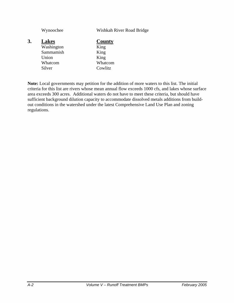
Wynoochee Wishkah River Road Bridge 3. Lakes County
Washington King Sammamish King Union King Whatcom Whatcom Silver Cowlitz
Note: Local governments may petition for the addition of more waters to this list. The initial criteria for this list are rivers whose mean annual flow exceeds 1000 cfs, and lakes whose surface area exceeds 300 acres. Additional waters do not have to meet these criteria, but should have sufficient background dilution capacity to accommodate dissolved metals additions from build-out conditions in the watershed under the latest Comprehensive Land Use Plan and zoning regulations.
A-2 Volume V – Runoff Treatment BMPs February 2005

Appendix V-B (Also published as Appendix III-D) Procedure for Conducting a Pilot Infiltration Test
The Pilot Infiltration Test (PIT) consists of a relatively large-scale infiltration test to better approximate infiltration rates for design of stormwater infiltration facilities. The PIT reduces some of the scale errors associated with relatively small-scale double ring infiltrometer or “stove-pipe” infiltration tests. It is not a standard test but rather a practical field procedure recommended by Ecology’s Technical Advisory Committee.
Infiltration Test
• Excavate the test pit to the depth of the bottom of the proposed infiltration facility. Lay back the slopes sufficiently to avoid caving and erosion during the test.
• The horizontal surface area of the bottom of the test pit should be approximately 100 square feet. For small drainages and where water availability is a problem smaller areas may be considered as determined by the site professional.
• Accurately document the size and geometry of the test pit.
• Install a vertical measuring rod (minimum 5-ft. long) marked in half-inch increments in the center of the pit bottom.
• Use a rigid 6-inch diameter pipe with a splash plate on the bottom to convey water to the pit and reduce side-wall erosion or excessive disturbance of the pond bottom. Excessive erosion and bottom disturbance will result in clogging of the infiltration receptor and yield lower than actual infiltration rates.
• Add water to the pit at a rate that will maintain a water level between 3 and 4 feet above the bottom of the pit. A rotameter can be used to measure the flow rate into the pit.
Note: A water level of 3 to 4 feet provides for easier measurement and flow stabilization control. However, the depth should not exceed the proposed maximum depth of water expected in the completed facility.
Every 15-30 min, record the cumulative volume and instantaneous flow rate in gallons per minute necessary to maintain the water level at the same point (between 3 and 4 feet) on the measuring rod.
Add water to the pit until one hour after the flow rate into the pit has stabilized (constant flow rate) while maintaining the same pond water level. (usually 17 hours)
After the flow rate has stabilized, turn off the water and record the rate of infiltration in inches per hour from the measuring rod data, until the pit is empty.
February 2005 Volume V – Runoff Treatment BMPs B-1

Data Analysis Calculate and record the infiltration rate in inches per hour in 30 minutes or one-hour increments until one hour after the flow has stabilized.
Note: Use statistical/trend analysis to obtain the hourly flow rate when the flow stabilizes. This would be the lowest hourly flow rate.
Apply appropriate correction factors for site heterogeneity, anticipated level of maintenance and treatment to determine the site-specific design infiltration rate (see Table 7.3).
Example
The area of the bottom of the test pit is 8.5-ft. by 11.5-ft.
Water flow rate was measured and recorded at intervals ranging from 15 to 30 minutes throughout the test. Between 400 minutes and 1,000 minutes the flow rate stabilized between 10 and 12.5 gallons per minute or 600 to 750 gallons per hour, or an average of (9.8 + 12.3) / 2 = 11.1 inches per hour.
Applying a correction factor of 5.5 for gravelly sand in table 6.3 the design long-term infiltration rate becomes 2 inches per hour, anticipating adequate maintenance and pre-treatment.
B-2 Volume V – Runoff Treatment BMPs February 2005
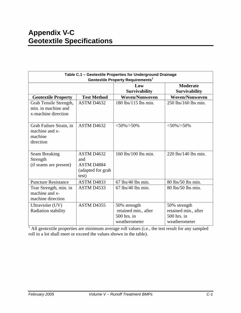
Appendix V-C Geotextile Specifications
Table C.1 – Geotextile Properties for Underground Drainage Geotextile Property Requirements1
Low Survivability
Moderate Survivability
Geotextile Property Test Method Woven/Nonwoven Woven/Nonwoven Grab Tensile Strength, min. in machine and x-machine direction
ASTM D4632 180 lbs/115 lbs min. 250 lbs/160 lbs min.
Grab Failure Strain, in machine and x-machine direction
ASTM D4632 <50%/>50% <50%/>50%
Seam Breaking Strength (if seams are present)
ASTM D4632 and ASTM D4884 (adapted for grab test)
160 lbs/100 lbs min. 220 lbs/140 lbs min.
Puncture Resistance ASTM D4833 67 lbs/40 lbs min. 80 lbs/50 lbs min. Tear Strength, min. in machine and x-machine direction
ASTM D4533 67 lbs/40 lbs min. 80 lbs/50 lbs min.
Ultraviolet (UV) Radiation stability
ASTM D4355 50% strength retained min., after 500 hrs. in weatherometer
50% strength retained min., after 500 hrs. in weatherometer
1 All geotextile properties are minimum average roll values (i.e., the test result for any sampled roll in a lot shall meet or exceed the values shown in the table).
February 2005 Volume V – Runoff Treatment BMPs C-1

Table C-2 – Geotextile for Underground Drainage Filtration Properties
Geotextile Property Requirements1
Geotextile Property
Test Method Class A Class B Class C
AOS2 ASTM D4751 .43 mm max. (#40 sieve)
.25 mm max. (#60 sieve)
.18 mm max. (#80 sieve)
Water Permittivity
ASTM D4491 .5 sec -1 min. .4 sec -1 min. .3 sec -1 min.
1 All geotextile properties are minimum average roll values (i.e., the test result for any sampled roll in a lot shall meet or exceed the values shown in the table). 2 Apparent Opening Size (measure of diameter of the pores in the geotextile)
Table C-3 – Geotextile Strength Properties for Impermeable Liner Protection
Geotextile Property Test Method Geotextile Property Requirements1
Grab Tensile Strength, min. in machine and x-machine direction
ASTM D4632 250 lbs min.
Grab Failure Strain, in machine and x-machine direction
ASTM D4632 >50%
Seam Breaking Strength (if seams are present)
ASTM D4632 and ASTM D4884 (adapted for grab test)
220 lbs min.
Puncture Resistance ASTM D4833 125 lbs min. Tear Strength, min. in machine and x-machine direction
ASTM D4533 90 lbs min.
Ultraviolet (UV) Radiation ASTM D4355 50% strength stability retained min., after 500 hrs. in weatherometer
1 All geotextile properties are minimum average roll values (i.e., the test result for any sampled roll in a lot shall meet or exceed the values shown in the table).
C-2 Volume V – Runoff Treatment BMPs February 2005

Applications
1. For sand filter drain strip between the sand and the drain rock or gravel layers specify Geotextile Properties for Underground Drainage, moderate survivability, Class A, from Tables 1 and 2 in the Geotextile Specifications.
2. For sand filter matting located immediately above the impermeable
liner and below the drains, the function of the geotextile is to protect the impermeable liner by acting as a cushion. The specification provided below in Table 3 should be used to specify survivability properties for the liner protection application. Table 2, Class C should be used for filtration properties. Only nonwoven geotextiles are appropriate for the liner protection application.
3. For an infiltration drain specify Geotextile for Underground Drainage,
low survivability, Class C, from Tables 1 and 2 in the Geotextile Specifications.
4. For a sand bed cover a geotextile fabric is placed exposed on top of the sand layer to trap debris brought in by the storm water and to protect the sand, facilitating easy cleaning of the surface of the sand layer. However, a geotextile is not the best product for this application. A polyethylene or polypropylene geonet would be better. The geonet material should have high UV resistance (90% or more strength retained after 500 hours in the weatherometer, ASTM D4355), and high permittivity (ASTM D4491, 0.8 sec. -1 or more) and percent open area (CWO-22125, 10% or more). Tensile strength should be on the order of 200 lbs grab (ASTM D4632) or more.
Courtesy of Tony Allen, Geotechnical Engineer-WSDOT
Reference for Tables 1 and 2: Section 9-33.2 “Geotextile Properties,” 1998 Standard Specifications for Road, Bridge, and Municipal Construction
February 2005 Volume V – Runoff Treatment BMPs C-3

C-4 Volume V – Runoff Treatment BMPs February 2005

Appendix V-D Turbulence and Short-Circuiting Factor
Figure D.1 – Recommended Values of F for Various Values of vH/Vt
February 2005 Volume V – Runoff Treatment BMPs D-1