Embed Size (px)
Citation preview
STORMWATER POLLUTION PREVENTION PLAN
Derwent Way Soil Transfer and Barge Facility
Prepared for:
SUMMIT EARTHWORKS INC. #109 – 32885 Mission Way
Mission, BC, V2V 6E4
Prepared by:
KEYSTONE ENVIRONMENTAL LTD. Suite 320 – 4400 Dominion Street
Burnaby, BC, V5G 4G3
Telephone: 604-430-0671 Facsimile: 604-430-0672
www.keystoneenvironmental.ca
Project No. 12943
Revision 3
May 2017
Stormwater Pollution Prevention Plan
Derwent Way Soil Transfer and Barge Facility
i Project 12943 / May 2017
PREFACE
This Stormwater Pollution Prevention Plan is designed to conform to the Port Metro Vancouver Guidelines for Developing Your Stormwater Pollution Prevention Plan in support of the conditions outlined in the Project & Environmental Review (PER No. 16-022) Application Submission Requirements dated February 16, 2015.
The Barge Loading Facility is a transfer facility for soils that have concentrations less than BC Hazardous Waste Regulation criteria. The transfer station facilitates delivery of contaminated soil to soil treatment facilities in the Lower Mainland and Fraser Valley.
Trucks bring soil to the facility where it is temporarily stored before being transferred to a barge for transport to an approved treatment facility in Mission BC.
Summit Earthworks Inc. (Summit) minimizes any possible impact of its operations by utilizing best available control technologies and operating procedures.
The purpose of this document is to provide stormwater management planning in conjunction with overall site planning, design, and future construction, beginning at the outset of the project.
Stormwater Pollution Prevention Plan
Derwent Way Soil Transfer and Barge Facility
iii Project 12943 / May 2017
TABLE OF CONTENTS
Page
INTRODUCTION ................................................................................................................ 1 1.
OVERVIEW ........................................................................................................................ 1 2.
2.1 Background ............................................................................................................... 1
2.2 Location ..................................................................................................................... 1
SITE INVENTORY ............................................................................................................. 2 3.
3.1 Activities .................................................................................................................... 2
3.2 Materials .................................................................................................................... 2
3.3 Hydrologic Assessment ............................................................................................. 2
3.3.1 Materials Storage Area ................................................................................ 3
3.3.2 Remaining Site Area ................................................................................... 3
ISSUES IDENTIFICATION AND RISK ANALYSIS ............................................................. 4 4.
4.1 Applicable Standards, Acts and Regulations .............................................................. 4
4.2 Potential Pollutant Sources ........................................................................................ 4
4.3 Potential Sensitive Receptors .................................................................................... 5
4.4 Identified Issues ......................................................................................................... 5
4.5 Identified Pollutant Pathways ..................................................................................... 5
STORMWATER POLLUTION PREVENTION PLAN .......................................................... 6 5.
5.1 Management Strategy ............................................................................................... 6
5.1.1 Prevention ................................................................................................... 6
5.1.2 Containment / Reduction ............................................................................. 7
5.1.3 Treatment .................................................................................................... 7
IMPLEMENTATION AND MONITORING ........................................................................... 8 6.
6.1 Implementation .......................................................................................................... 8
6.2 Site Monitoring ........................................................................................................... 8
6.3 Adaptive Management and Continuous Improvement ................................................ 9
LIST OF APPENDICES
Appendix A Site Drainage Plan Appendix B Stormwater Design Calculations
Stormwater Pollution Prevention Plan
Derwent Way Soil Transfer and Barge Facility
1 Project 12943 / May 2017
INTRODUCTION 1.
Stormwater originates from precipitation events (such as rainfall) and from snow and ice melt. Stormwater remains on the ground surface through ponding, gets soaked into the ground, or becomes stormwater runoff, which ultimately enters nearby bodies of water. Stormwater runoff flows over land or impervious surfaces such as paved roadways, parking spaces and material storage area. As it flows it accumulates debris, soil and sediment, and contaminants that could negatively impact water quality.
This Stormwater Pollution Prevention Plan (SPPP) has been developed for a proposed Barge Loading Facility. The site is located in an unimproved industrial area.
The purpose of the SPPP is to develop a pollutant control strategy to minimize the discharge of pollutants by stormwater runoff. Best Management Practices (BMPs) are those practices that are considered sound, relatively low in cost, and applicable to a broad category of industries and types of pollutants. Advanced BMPs are defined as those that are specific to a type of industry or pollutant. The BMPs discussed in this plan have been designed to improve the quality of stormwater discharged from the facility and to aid in the development, implementation and evaluation of the SPPP.
OVERVIEW 2.
2.1 Background
The Barge Loading Facility will accept contaminated soils that have been confirmed not to be hazardous waste. The transfer station will facilitate delivery of contaminated soil to soil treatment facilities in the Lower Mainland and Fraser Valley. Trucks will bring soil to the facility where it will be temporarily stored in a ‘Materials Storage Area’ before being transferred to a barge and transported to an approved treatment facility.
The site will be self-contained and will have emergency procedures in place. A Spill Response Plan is available for this site and should be reviewed in the context of this SPPP.
2.2 Location
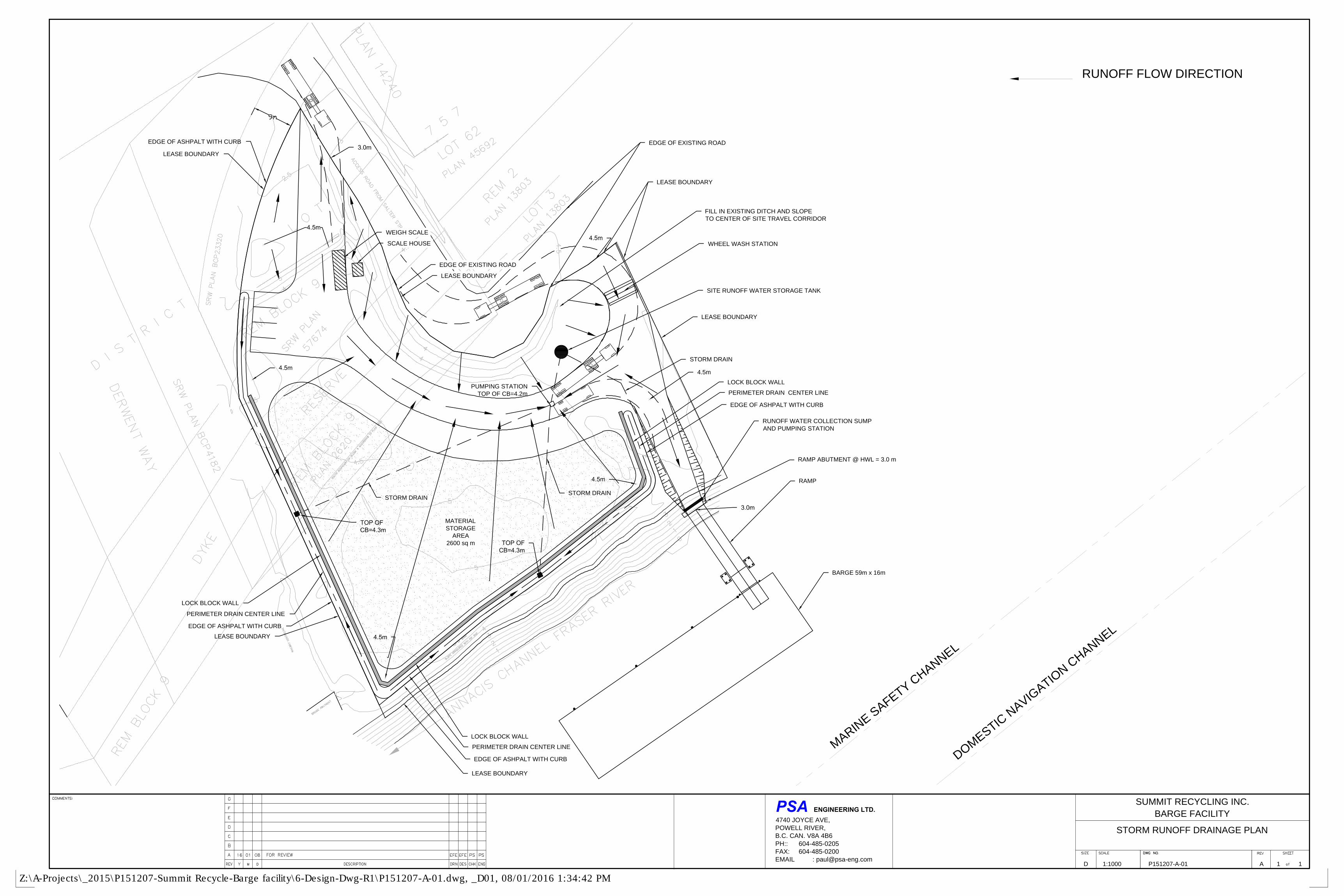
The Barge Loading Facility is to be located on Derwent Way in New Westminster, BC, on the northern bank of the Fraser River. The upland portion of the Project site is bounded to the north by a rail right-of-way and paved access road from Salter Street, a paved shipping container storage lot to the east, the Fraser River to the south, and a rail right-of-way and Derwent Way to the west (see Lease Plan No. 2016-015 in Appendix A). The area is largely industrial, with residential housing on the western side of Derwent Way. The Project site area (upland and water lease lot) is approximately 7,100 m2, and approximately 100 m wide along the Fraser River bank.

Stormwater Pollution Prevention Plan
Derwent Way Soil Transfer and Barge Facility
2 Project 12943 / May 2017
SITE INVENTORY 3.
3.1 Activities
Over the lifecycle of the site, the Barge Loading Facility is expected to engage in the activities listed below that have the potential to expose stormwater runoff to contaminants. Drawing No. P151207-A-01 shows the proposed facility plan.
• Soil off-loading
• Barge loading
• Refuelling of site equipment
3.2 Materials
The significant materials expected to be exposed to stormwater at the Barge Loading Facility include the following:
• Waste and Industrial Land Use Classified Soils
• Petroleum fuels and oils associated with refuelling and maintaining onsite equipment
3.3 Desktop Hydrologic Assessment
A desktop hydrologic assessment was conducted based on the proposed final design of the site, in order to estimate the stormwater runoff response, including peak flow rates and runoff volumes for various rainfall events. The design of the site stormwater management system will take into account the results of the hydrological assessment to provide adequate stormwater infrastructure for the site.
For the purpose of the desktop hydrologic assessment, the Site was divided into two sub-catchment areas as follows:
• Materials Storage Area – 0.26 hectares
• Remaining Site Area – 0.45 hectares
Stormwater and runoff from the Materials Storage Area will be collected in several catch basins and will flow by gravity to a main pumping station. The site area outside of the Materials Storage Area will primarily also flow to the main pumping station, with the exception of the slope area down to the floating barge ramp, which will flow to a separate small sump. The sloped area down to the floating barge ramp has an approximate surface area of 250 m2. Both the main pumping station and the small sump will convey the captured stormwater runoff to holding tanks located on the site.
The Materials Storage Area has the potential to generate a higher concentration of solids and contaminant runoff while the soil stockpiles are temporarily uncovered. During a storm event a primary response action on site will be to cover the stockpiles to prevent runoff. As a result,
Stormwater Pollution Prevention Plan
Derwent Way Soil Transfer and Barge Facility
3 Project 12943 / May 2017
contaminant loading from the Materials Storage Area will primarily be in the initial interval of the storm event. For the remaining site area, solids and oils accumulated on the roadway will be re-suspended and entrained following a precipitation event. It has been shown that the first rain after a dry period has a greater concentration of contaminants for a short period of time. This initial surface water runoff is known as the “first flush”. After the first flush, research has shown that there is a rapid decrease in the contaminant loading in stormwater runoff. For this reason, this SPPP focusses on collecting the first flush water for a high level of treatment. Stormwater collected after the first flush will also be sent for treatment, but the treatment may not be as extensive.
3.3.1 Materials Storage Area
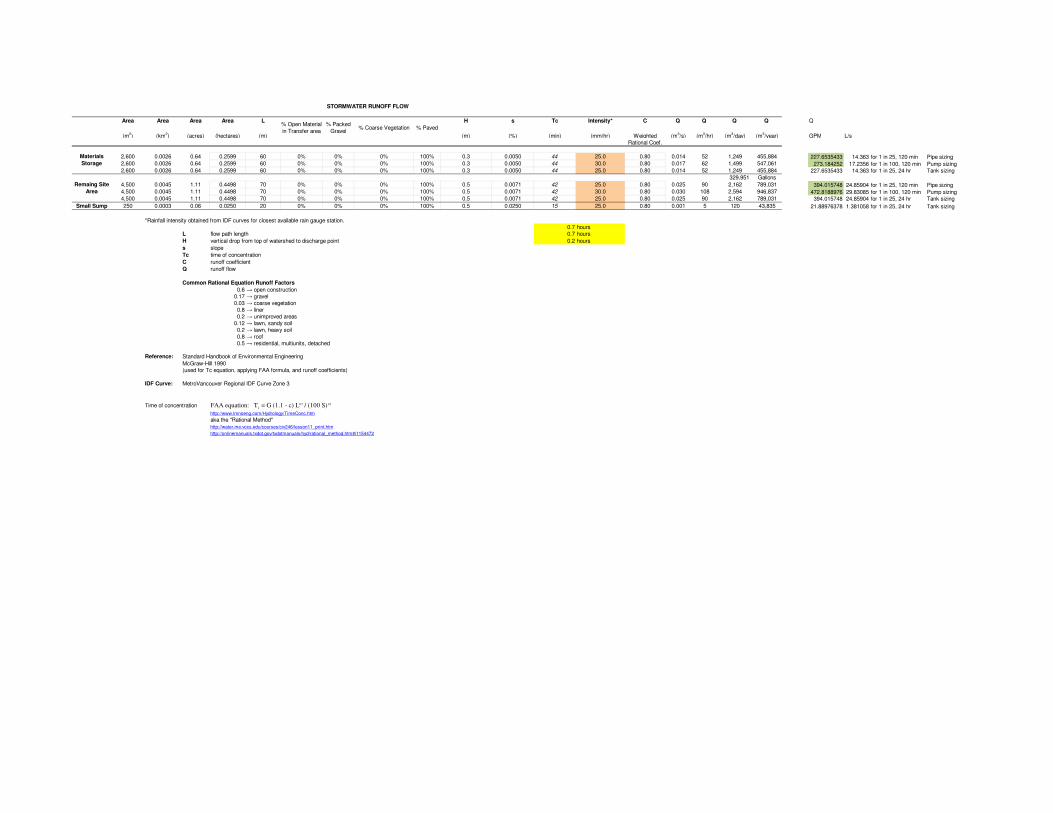
The following hydrological parameters were used to model hydrological properties of the proposed design with respect to the Materials Storage Area:
• Materials Storage Area – 0.26 hectares
• Current design impervious area – 100%
• Average slope – 0.5%
• Time of concentration – From furthest point in material storage area to pumping station: 44 min
• Metro Vancouver Regional IDF Curve Zone 3
The peak flow was calculated to determine sizing for pumps and piping. Based on the time of concentration, and a 25-year return period event, with a peak rainfall intensity of 25 mm/hr, a peak flow of approximately 14 L/s (227 GPM) is expected. For a 100-year return period event, a peak flow of approximately 17 L/s (273 GPM) is expected.
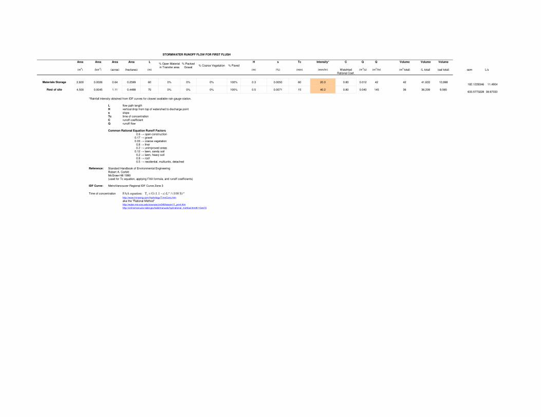
The “first flush” was calculated by assuming that the entirety of precipitation during a 1-hour, 25-year storm event is to be contained on-Site for treatment in the Materials Storage Area. The total first flush volume is estimated to be 42,000 L (11,000 gallons).
3.3.2 Remaining Site Area
The following hydrological parameters were used to model hydrological properties of the proposed design with respect to the Remaining Site Area:
• Remaining Site Area – 0.45 hectares (250 m2 to small sump)
• Current design impervious area – 100%
• Average slope – 0.7%
• Time of concentration – From furthest point in Material Storage Area to pumping station: 42 min (to main pumping station), 15 min to small sump
• Metro Vancouver Regional IDF Curve Zone 3
Stormwater Pollution Prevention Plan
Derwent Way Soil Transfer and Barge Facility
4 Project 12943 / May 2017
The peak flow during was calculated to determine sizing for pumps and piping. Based on the time of concentration, and a 25-year return period event, with a peak rainfall intensity of 25 mm/hr, a peak flow of approximately 25 L/s (395 GPM) is expected. For a 100-year return period event, a peak flow of approximately 30 L/s (472 GPM) is expected.
The “first flush” was calculated by assuming that the entirety of precipitation during a 15 minute, 25-year storm event is to be contained on-Site for treatment in the Remaining Site Area. The total first flush volume is estimated to be 36,000 L (9,500 gallons).
ISSUES IDENTIFICATION AND RISK ANALYSIS 4.
4.1 Applicable Standards, Acts and Regulations
The following relevant legislation and standards are applicable given the potential pollutant sources listed above.
• Canada Fisheries Act regarding the deposition of deleterious substance in water frequented by fish
• Canada Shipping Act, National Spill Response Protocol regarding the release of pollutants to the marine environment
• Canada Environmental Protection Act regarding pollution prevention
• Canadian Council of Ministers of the Environment (CCME) Guidelines relating to water quality standards
• BC Environmental Management Act, regarding pollution prevention
• Corporation of the City of New Westminster Sewerage and Drainage Regulation (Bylaw No. 7746, 2015)
4.2 Potential Pollutant Sources
An assessment was conducted to identify materials and practices which may reasonably be expected to add significant levels of pollutants to stormwater or that may result in the discharge of pollutants during dry weather from separate storm sewers draining from the facility. This section will provide a description of potential sources that may contribute to the presence of contaminants in stormwater runoff.
• Soil receiving, handling, transfer, storage and ship loading could result in soil being spilled onto the ground.
• Dust from the temporary soil piles during dry weather periods.
• Fuel, oil or coolant from service vehicles or barges could leak due to damage, normal wear and tear or during fuelling or preventative maintenance.
Stormwater Pollution Prevention Plan
Derwent Way Soil Transfer and Barge Facility
5 Project 12943 / May 2017
4.3 Potential Sensitive Receptors
The Fraser River is a potential sensitive receptor, and provides habitat for fish.
4.4 Identified Issues
No outstanding issues have been identified at this time. Section 5.1 below outlines the Management Strategy to address prevention, containment, reduction, and treatment measures.
4.5 Identified Pollutant Pathways
In order to move soil to and from the material storage area, trucks and site equipment must manoeuvre around the Site. A 9,500 litre, above-ground storage tank (AST) may be present on Site for fuelling of site equipment. This storage tank will either be a double-lined vacuum-monitored tank or will be a single-walled tank placed within a secondary containment area. Engineered drawings will be produced for the tank and the design will be registered with the Petroleum and Allied Petroleum Products Storage Tanks Regulations. Fuelling will be completed at a minimum distance of 30 m from the high water mark.
The Material Storage Area will be lined using a 30 mil high density polyethylene (HDPE) liner under an asphalt cover, in order to prevent runoff water from this area from infiltrating into the ground. In addition, the Material Storage Area will be isolated from the broader site area via a 30 cm high concrete curb. This will inhibit the ability of stormwater runoff from either running into, or out of the Material Storage Area via overland flow. Drawing 16-12943-01 appended to this plan shows cross-sections and details of the lined and paved area. All rainfall and snowmelt that falls within the Material Storage Area will be directed via overland flow to a single pumping station within the contained material storage area. In addition, the liner will also be hydraulically connected to the pumping station should the asphalt cover be compromised and rainfall or snowmelt penetrate the surface. Soils placed within the temporary storage area will be covered with a poly cover when the area is not in use to prevent infiltration and runoff from the soil piles. The soil piles will also be covered at the end of each work day, and when rainfall warnings are forecast by Environment Canada.
The lift station will be arranged such that the first flush1 water from the temporary soil storage area will be captured and pumped to the onsite water storage tanks. Water collected from the truck wash will also be pumped to the water storage tanks.
Water in the storage water tanks will be treated as described in Section 5.1.3 below, prior to discharge to the sanitary sewer. Following the first flush period, surface water runoff generated within the material storage area will by-pass the water treatment system and be transferred directly to the oil water separator and sediment trap, prior to discharge to the storm sewer.
The remaining site area will be graded so that all rainfall and snow melt is directed into a separate network of catch basins and subgrade storm drains that flow to an oil/ water separator. One area located near the base of the barge ramp will have a lift station that will transfer the
1 1-hour duration, 25 year return period catchment volume.
Stormwater Pollution Prevention Plan
Derwent Way Soil Transfer and Barge Facility
6 Project 12943 / May 2017
collected water to the holding tanks for treatment. The treated stormwater will be discharged to the sanitary sewer.
Surface water discharged from the Site in accordance with the Corporation of the City of New Westminster Sewerage and Drainage Regulation (Bylaw No. 7746, 2015).
A detailed site drainage plan drawing including the pumping stations and the site runoff water storage tanks is presented on PSA Engineering Ltd. Stormwater Drainage Plan.
STORMWATER POLLUTION PREVENTION PLAN 5.
5.1 Management Strategy
The Barge Loading Facility stormwater pollution prevention strategy is to implement a set of BMPs to target the potential pollutant sources identified in Section 4.2 of this plan. These practices will encompass prevention, containment/reduction, and treatment.
5.1.1 Prevention
Maintenance of work areas that may contribute pollutants to stormwater will be the most effective management practice for this site. Good housekeeping practices are not only beneficial in terms of limiting exposure of materials to stormwater, but they also improve worker safety and often contribute to reducing losses of products, thereby lowering operational or capital costs.
The Barge Loading Facility will employ a preventive maintenance program that includes inspections, testing, maintenance, and repairs of facility equipment and systems whose failure could result in the discharge of sediment laden stormwater.
The temporary soil stockpiles will be covered with low permeable tarps during rainfall events and during periods of high wind to prevent water contact with the soil and reduce the potential for dust. The site will also be swept regularly to minimize interaction between the soil and rainfall runoff.
Leachable toxic wastes will not be accepted at this facility and thus rainfall is not expected to generate significant contaminants in the pile runoff. The first flush is expected to wash down the majority of dirt and oils accumulated on the site roads that will be captured for treatment. The separator (discussed in Section 5.1.3 below) will be used for polishing low residual concentrations not collected as part of the first flush.
The Material Storage Area will be completely contained such that surface water runoff generated in this area is contained within a separate drainage network to the surface water runoff generated from the remaining Site area. This includes a 30 mil HDPE liner to prevent infiltration into the underlying subgrade.
Discharge from the water storage tanks will be limited to batch discharge following water sampling. Where the water quality is determined to be unsuitable for discharge with respect to the permit criteria, the water will be treated a second time, or until the water quality is considered suitable for discharge.
Stormwater Pollution Prevention Plan
Derwent Way Soil Transfer and Barge Facility
7 Project 12943 / May 2017
The AST will be double-lined and stored within a tertiary concrete containment structure. No barge or truck refuelling will take place on-Site or within the water lot; only certified Site equipment will be refuelled and will be contained within the designated refuelling area. The nozzle will be complete with an automatic shutoff valve and will house a spill kit within 10 m of the refuelling area compound.
5.1.2 Containment / Reduction
Trucks and cars parked for more than one day will be parked within a designated area with a drip tray underneath the motor to prevent potential oil leaks.
In areas where there is a likelihood of solid contaminants entering a waste water drain, the drain will be equipped with a filter bag to reduce the amount of solids allowed to enter the storm drain.
5.1.3 Treatment
Four (4) 19,000 litre water storage tanks will be required on site in order to provide sufficient storage for the first flush runoff volume from the material storage area as described above. The tank will be designed to manage storm water for the first hour of a 25 year storm event and will also have capacity to manage wash water from the on-site truck washing station. It should be noted that by utilising BMPs, first flush runoff from the Remaining Site Area is considered unlikely to generate significant deleterious material that requires management outside of what the oil water separator provides. As such, only first flush water from the Materials Storage Area will be directed to the water storage tanks. For rain events where the holding capacity of the water storage tanks is exceeded, overflow water will be directed from the water storage tanks to the oil water separator.
Stormwater within the water storage tanks will be directed to the chemical and physical gravitational separation water treatment system. The dose rate and treatment chemical will be adjusted regularly, and will be based on the different contaminants of potential concern associated with each different delivery of soil material to Site. As required, secondary and tertiary treatment of this collected water will be completed until such time as the water is of a suitable quality such that it can be discharged to the sanitary sewer under permit. The water will be tested prior to discharge for the contaminants of potential concern associated with each delivery of soil. The treated water will be discharged to the sanitary sewer that will be extended on to the site during site development.
Runoff water from the Remaining Site Area will be collected and sent through an oil water separator prior to being discharged through a sediment trap to the City of New Westminster storm drainage system. The oil water separator will be sized to treat normal flow scenario of 10 L/s and a maximum design flow of 32 L/s, which exceeds design storm flow for the entire Site. Any flow generated on the Site which exceeds the 32 L/s, will be directed to an engineered overflow system so as to not disrupt and scour the oil and sediment collected within the oil water separator. The oil water separator will be an Armtec Vortech system (or pre-approved equivalent).
Stormwater Pollution Prevention Plan
Derwent Way Soil Transfer and Barge Facility
8 Project 12943 / May 2017
Other measures that will be put in place are:
• Sediment barriers such as silt fencing or fiber rolls (as needed based on on-Site observations, these will be available on Site to be used if required)
• Wheel washes and truck washes (located at the entrance of the Site)
• Good housekeeping practices and regular Site cleanup and maintenance
IMPLEMENTATION AND MONITORING 6.
6.1 Implementation
The Barge Loading Facility Site manager will be responsible for the implementation of this plan.
The manager will possess the knowledge and skills to assess conditions and activities that could impact stormwater quality at the facility, and who can also evaluate the effectiveness of
the management practices. They shall educate other Site personnel in the application of this
plan and the importance of adhering to each BMP as described in this document.
All Site staff involved in regular site operations and activities will receive training on the contents
of this plan at hire orientation and annually. The training will clearly indicate that it is the responsibility of all staff to be able to recognize ineffective stormwater management practices
and to report them to the site manager.
6.2 Site Monitoring
Regular site and effluent inspections shall be conducted by the manager to confirm that stormwater BMPs outlined in this plan are being implemented effectively and to identify possible
concerns related to the quality of stormwater effluent.
At a minimum, the manager will conduct weekly inspections of all areas of the facility where
industrial materials or activities are exposed to stormwater and/or where the potential for
exposure to stormwater exists. Such areas specifically include the soil receiving areas, soil storage areas, and soil load-out areas.
In addition to the weekly inspections, the manager will monitor local weather reports for upcoming storm events and conduct inspections during a period when a stormwater discharge
is occurring.
The water quality of stormwater within the water storage tanks will be tested for each proposed discharge, or ‘batch’. Each batch will be tested for a specific analytical suite based on the
contaminants of potential concern associated with each load of soil delivered the Site. Each soil
load will be delivered with a soil quality report completed by a suitably qualified environmental professional or certified laboratory data. The analytical suite will typically include pH, total
suspended solids, heavy metals and various hydrocarbons. In addition to the chemical
composition of the ‘batch’, visual and olfactory signs of contamination such as odour, foam, discoloration, sediment or an oily sheen will be assessed prior to any discharge.

Stormwater Pollution Prevention Plan
Derwent Way Soil Transfer and Barge Facility
9 Project 12943 / May 2017
All weekly and storm event inspections, as well as ‘batch’ water quality sampling events will be
documented along with any repairs/maintenance of the existing stormwater management works, any new management works proposed, the personnel responsible for maintenance or
installation and a timeline for completion of the prescribed maintenance or installation.
6.3 Adaptive Management and Continuous Improvement
A key process in the effective implementation of the SPPP is the ability to change mitigation measures or actions as site conditions warrant in order to protect stormwater quality.
This approach, generally termed as ‘adaptive management’, is a planned and systematic
process for continuously improving environmental management practices by learning about their outcomes.
The Barge Loading Facility manager will review the contents of this plan on an annual basis to ensure continuous improvement for the stormwater system, that all potential stormwater
exposures have been identified, and that the management practices are appropriate and
adequate. The inspection reports will be reviewed for trends in effective and ineffective
mitigation actions and measures. The results of these reviews may determine that current stormwater management procedures are working effectively or additional mitigation efforts
are needed.
Stormwater Pollution Prevention Plan
Derwent Way Soil Transfer and Barge Facility
10 Project 12943 / May 2017
LIMITATIONS 7.
Findings presented in this plan are based upon (i) a desktop review of client-provided drawings for the proposed works on the subject site, and (ii) a literature review of applicable values for hydrological parameters. Calculations and estimations reflect conditions expected at the specific site location at the time the work was conducted. Site conditions may vary from that extrapolated from the data collected during this investigation. Consequently, while findings and conclusions documented in this plan have been prepared in a manner consistent with that level of skill and care normally exercised by other members of the environmental science and engineering profession practising under similar circumstances in the area at the time of the performance of the work, this plan is not intended, nor is it able, to provide a totally comprehensive review of past, present, or future site environmental conditions. This plan must be read and used in its entirety.
We trust this information meets your requirements at this time. Please contact us should you have any questions.
Sincerely,
Keystone Environmental Ltd. Alice Kruchten, EIT Jason Christensen, P.Eng. Environmental Engineer Senior Engineer
APPENDIX A
SITE DRAINAGE PLAN
ENGINEERING LTD.
4740 JOYCE AVE,
POWELL RIVER,
B.C. CAN. V8A 4B6
PH:: 604-485-0205
FAX: 604-485-0200
EMAIL : [email protected]
PSA
11AP151207-A-011:1000D
STORM RUNOFF DRAINAGE PLAN
BARGE FACILITY
SUMMIT RECYCLING INC.
4.5m
PUMPING STATION
TOP OF CB=4.2m
SITE RUNOFF WATER STORAGE TANK
WHEEL WASH STATION
RAMP
BARGE 59m x 16m
RAMP ABUTMENT @ HWL = 3.0 m
EDGE OF EXISTING ROAD
FILL IN EXISTING DITCH AND SLOPE
TO CENTER OF SITE TRAVEL CORRIDOR
RUNOFF FLOW DIRECTION
STORM DRAIN
STORM DRAIN
STORM DRAIN
MATERIAL
STORAGE
AREA
2600 sq m
LOCK BLOCK WALL
RUNOFF WATER COLLECTION SUMP
AND PUMPING STATION
LEASE BOUNDARY
LEASE BOUNDARY
PERIMETER DRAIN CENTER LINE
EDGE OF ASHPALT WITH CURB
LOCK BLOCK WALL
PERIMETER DRAIN CENTER LINE
EDGE OF ASHPALT WITH CURB
LOCK BLOCK WALL
PERIMETER DRAIN CENTER LINE
EDGE OF ASHPALT WITH CURB
EDGE OF ASHPALT WITH CURB
LEASE BOUNDARY
LEASE BOUNDARY
EDGE OF EXISTING ROAD
LEASE BOUNDARY
LEASE BOUNDARY
SCALE HOUSE
WEIGH SCALE
M
A
R
I
N
E
S
A
F
E
T
Y
C
H
A
N
N
E
L
D
O
M
E
S
T
I
C
N
A
V
I
G
A
T
I
O
N
C
H
A
N
N
E
L
Z:\A-Projects\_2015\P151207-Summit Recycle-Barge facility\6-Design-Dwg-R1\P151207-A-01.dwg, _D01, 08/01/2016 1:34:42 PM
APPENDIX B
STORMWATER DESIGN CALCULATIONS
STORMWATER RUNOFF FLOW
Area Area Area Area L H s Tc Intensity* C Q Q Q Q Q
(m2) (km
2) (acres) (hectares) (m) (m) (%) (min) (mm/hr) Weighted (m
3/s) (m
3/hr) (m
3/day) (m
3/year) GPM L/s
Rational Coef.
2,600 0.0026 0.64 0.2599 60 0% 0% 0% 100% 0.3 0.0050 44 25.0 0.80 0.014 52 1,249 455,884 227.6535433 14.363 for 1 in 25, 120 min Pipe sizing2,600 0.0026 0.64 0.2599 60 0% 0% 0% 100% 0.3 0.0050 44 30.0 0.80 0.017 62 1,499 547,061 273.184252 17.2356 for 1 in 100, 120 min Pump sizing2,600 0.0026 0.64 0.2599 60 0% 0% 0% 100% 0.3 0.0050 44 25.0 0.80 0.014 52 1,249 455,884 227.6535433 14.363 for 1 in 25, 24 hr Tank sizing
329,951 Gallons
4,500 0.0045 1.11 0.4498 70 0% 0% 0% 100% 0.5 0.0071 42 25.0 0.80 0.025 90 2,162 789,031 394.015748 24.85904 for 1 in 25, 120 min Pipe sizing4,500 0.0045 1.11 0.4498 70 0% 0% 0% 100% 0.5 0.0071 42 30.0 0.80 0.030 108 2,594 946,837 472.8188976 29.83085 for 1 in 100, 120 min Pump sizing4,500 0.0045 1.11 0.4498 70 0% 0% 0% 100% 0.5 0.0071 42 25.0 0.80 0.025 90 2,162 789,031 394.015748 24.85904 for 1 in 25, 24 hr Tank sizing
Small Sump 250 0.0003 0.06 0.0250 20 0% 0% 0% 100% 0.5 0.0250 15 25.0 0.80 0.001 5 120 43,835 21.88976378 1.381058 for 1 in 25, 24 hr Tank sizing
*Rainfall intensity obtained from IDF curves for closest available rain gauge station.
0.7 hours
L flow path length 0.7 hours
H vertical drop from top of watershed to discharge point 0.2 hours
s slope
Tc time of concentration
C runoff coefficient
Q runoff flow
Common Rational Equation Runoff Factors
0.6 → open construction
0.17 → gravel
0.03 → coarse vegetation
0.8 → liner
0.2 → unimproved areas
0.12 → lawn, sandy soil
0.2 → lawn, heavy soil
0.8 → roof
0.5 → residential, multiunits, detached
Reference: Standard Handbook of Environmental Engineering
McGraw-Hill 1990
(used for Tc equation, applying FAA formula, and runoff coefficients)
IDF Curve: MetroVancouver Regional IDF Curve Zone 3
Time of concentration FAA equation: Tc = G (1.1 - c) L0.5 / (100 S)1/3
http://www.lmnoeng.com/Hydrology/TimeConc.htm
aka the "Rational Method"
http://water.me.vccs.edu/courses/civ246/lesson11_print.htm
http://onlinemanuals.txdot.gov/txdotmanuals/hyd/rational_method.htm#i1154472
% Open Material
in Transfer area
% Packed
Gravel% Coarse Vegetation % Paved
Materials
Storage
Remaing Site
Area
STORMWATER RUNOFF FLOW FOR FIRST FLUSH
Area Area Area Area L H s Tc Intensity* C Q Q Volume Volume Volume
(m2) (km
2) (acres) (hectares) (m) (m) (%) (min) (mm/hr) Weighted (m
3/s) (m
3/hr) (m
3 total) (L total) (gall
total) gpm L/s
Rational Coef.
Materials Storage 2,600 0.0026 0.64 0.2599 60 0% 0% 0% 100% 0.3 0.0050 60 20.0 0.80 0.012 42 42 41,633 10,998182.1228346 11.4904
Rest of site 4,500 0.0045 1.11 0.4498 70 0% 0% 0% 100% 0.5 0.0071 15 40.2 0.80 0.040 145 36 36,209 9,565633.5773228 39.97333
*Rainfall intensity obtained from IDF curves for closest available rain gauge station.
L flow path length
H vertical drop from top of watershed to discharge point
s slope
Tc time of concentration
C runoff coefficient
Q runoff flow
Common Rational Equation Runoff Factors
0.6 → open construction
0.17 → gravel
0.03 → coarse vegetation
0.8 → liner
0.2 → unimproved areas
0.12 → lawn, sandy soil
0.2 → lawn, heavy soil
0.8 → roof
0.5 → residential, multiunits, detached
Reference: Standard Handbook of Environmental Engineering
Robert A. Corbitt
McGraw-Hill 1990
(used for Tc equation, applying FAA formula, and runoff coefficients)
IDF Curve: MetroVancouver Regional IDF Curve Zone 3
Time of concentration FAA equation: Tc = G (1.1 - c) L0.5 / (100 S)1/3
http://www.lmnoeng.com/Hydrology/TimeConc.htm
aka the "Rational Method"
http://water.me.vccs.edu/courses/civ246/lesson11_print.htm
http://onlinemanuals.txdot.gov/txdotmanuals/hyd/rational_method.htm#i1154472
% Open Material
in Transfer area
% Packed
Gravel% Coarse Vegetation % Paved